1
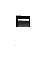
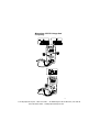
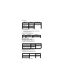
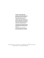
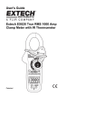
#61-350 #61-352 #61-354(TRMS) 350 Series Digital Multimeter 99 Washington Street Melrose, MA 02176 Fax 781-665-0780 TestEquipmentDepot.com 1 Features Auto / Manual Ranging Non-Contact Voltage (NCV) 80-600V AC Measures AC/DC Current (352 and 354 only) Measures AC/DC Voltage and Resistance Measures Frequency and Capacitance (352 and 354 only) Audible Continuity Data Hold Low Battery Indication Auto Power Off Large Numbers and Symbols Electronic overload protection on all ranges Warning Safety sheet .......... .......... .......... ........ ......... .......... .......... ........ ......... 2 Read First 2 Safety Information Understand and follow operating instructions carefully. Use the meter only as specified in this manual; otherwise, the protection provided by the meter may be impaired. WARNING To avoid possible electric shock, personal injury or death, follow these instructions: ․ Do not use if meter appears damaged, Visually inspect the meter to ensure case is not cracked and back case is securely in place. ․ Inspect and replace leads if insulation is damaged,metal is exposed or probes are cracked. Pay particular attention to the insulation surrounding the connectors. ․ Do not use Meter if it operates abnormally as protection maybe impaired. ․ Do not use during electrical storms or in wet weather. ․ Do not use around explosive gas, dust or vapor. ․ Do not apply more than the rated voltage to the meter. ․ Do not use without the battery and the back case properly installed. 2 ․ Remove the test leads from the circuit prior to removing battery cap. ․ Do not attempt to repair this unit as it has no userserviceable parts. ․ Voltages exceeding 30VAC or 60VDC pose a shock hazard so use caution. CAUTION To protect yourself, think “Safety First”: ․ Use appropriate personal protective equipment such as safety glasses, face shields, insulating gloves, insulating boots and/or insulating mats. ․ Before each use. - Perform a continuity test by touching the test leads together to verify the functionally of the battery and test leads. - Use the 3 Point Safety Method. (1) Verify meter operation by measuring a known voltage. (2) Apply meter to circuit under test. (3) Return to the known live voltage again to ensure proper operation. ․ Never ground yourself when taking electrical measurements. ․ Connect the black common lead to ground or neutral before applying the red test lead to potential voltage. Disconnect the red test lead from the voltage first. ․ Always work with a partner. ․ When using the probes, keep fingers as far behind the probe tips as possible. ․ Never connect a source of voltage with the function rotary switch in Ω/ :</ A //Hz position.Never set the meter in A function to measure the voltage of a power supply circuit in equipment that could result in damage to the meter and the equipment under test. 3 Symbols as marked on the meter and Instruction card Risk of electric shock See instruction card DC measurement Equipment protected by double or reinforced insulation Battery Fuse Earth AC measurement Conforms to EU directives 4 Measuring AC/DC Voltage And Frequency 5 Test Equipment Depot - 800.517.8431 - 99 Washington Street Melrose, MA 02176 FAX 781.665.0780 - TestEquipmentDepot.com Resistance Disconnect Circuit Power off 1 F/630V Discharge hight-voltage Capacitor Testing for Continuity 6 Testing for Diode Bad Diode Red Black Red Black Red Black Good Diode Red Black Measuring DC / AC Current (For 352,354 only) Disconnect 7 Measuring Capacitance (For 352,354 only) MIN MAX Record 8 Display Hold Manual Ranging and Auto Ranging Auto Power Off (Battery Saver) 10 min 9 Disable Auto Power Off Non-Contact Voltage (NCV) NCV 1. NCV switch will be activated on any function or at OFF status. 2. Test leads are not used for the NCV test. 3. Press the NCV button. The display goes black, a tone sounds and the red LED lights up to verify the instrument is operational. The NCV button must be held down to detect the presence of voltage without use of the leads. 10 Test Equipment Depot - 800.517.8431 - 99 Washington Street Melrose, MA 02176 FAX 781.665.0780 - TestEquipmentDepot.com Fuse Replacement (For 352 & 354 only) Refer to the following figure to replace fuse : Caution ․ Use only a fuse with the amperage, interrupt, voltage, and speed rating specified. ․ Fuse rating : 10A, 500V Battery Replacement Refer to the following figure to replace the batteries : Caution ․ Replace the batteries as soon as the low batteries indicator "" appears, to avoid false reading. ․ Batteries 1.5V x 2 11 Maintenance Do not attempt to repair this Meter. It contains no user-serviceable parts. Repair or servicing should only be performed by qualified personnel. Cleaning Periodically wipe the case with a dry cloth and detergent. Do not use abrasives or solvents. Specifications General Specifications Display : 2000 counts updates 1.5/sec. Polarity Indication : Automatic, positive implied, negative indicated. Overrange Indication : “OL” or “-OL”. Batteries Life : Alkaline 250 hours Low Batteries Indication : “” is displayed when the batteries voltage drops below operating voltage. Auto Power Off : Approx 10 minutes. Operating Ambient : Non-condensing ≦50°F, 51.8°F ~ 86°F (≦80% R.H) 87.8°F ~ 104°F (≦75% R.H), 105.8°F ~ 122°F (≦45% R.H), Storage Temperature : -4°F to 140°F , 0 to 80% R.H. when battery removed from Meter. Temperature Coefficient : 0.15 x (Spec.Accy) / °F ,< 64.4°F or > 82.4°F. Power Requirements : 1.5V x 2 IEC LR03, AM4 or AAA size Dimensions (W x H x D) : 2.91 in. x 6.14 in. x 1.34 in. without holster. 3.15 in. x 6.45 in. x 1.73 in. with holster. Accessories : Battery (installed), Test leads and user manual. Measure : Samples 2 times per second nominal. Altitude : 6561.7 ft (2000m) Safety : Complies with EN61010-1, UL61010-1, IEC 61010-1, CAT.III. 600V, CAT.II. 1000V. Weight : 11.3 oz (320g) including battery. 12 Electrical Specifications Accuracy is ±(% reading + number of digits) at 23°C ± 5°C < 80%RH. DC / AC Volts Range AC Accuracy 200.0mV * Unspecified 2.000V * 20.00V ~ 200.0V * ± (1.5%+5dgt) 50Hz~300Hz ± (1.5%+5dgt) 50Hz~500Hz * 750V AC / 1000V DC DC Accuracy : ±(0.5% + 2dgt) Over voltage protection : 1000V DC or 750 V AC rms. Input Impedance : 10MΩ // less than 100pF. * CMRR / NMRR : (Common Mode Rejection Ratio) (Normal Mode Rejection Ratio) VAC : CMRR > 60dB at DC, 50Hz / 60Hz VDC : CMRR > 100dB at DC, 50Hz / 60Hz NMRR > 50dB at DC, 50Hz / 60Hz AC Conversion Type : Average sensing rms indication. AC conversions are ac-coupled, true rms responding, calibrated to the sine wave input. * The minimum LCD reading is 1400 count in Auto Ranging Mode. Crest Factor : C.F. = Peak / Rms + 1.5% addition error for C.F. from 1.4 to 3 + 3% addition error for C.F. from 3 to 4 DC / AC Current (For 352 & 354 only) AC Accuracy Voltage Burden ±(1.5% + 5 dgt) ±(1.0% + 3 dgt) 50Hz ~ 500Hz 10.00A ** * 2V max Range DC Accuracy 2.000A Overload Protection : A input : 10A (500V) fast blow fuse * AC Conversion Type : Conversion type and additional specification are same as DC/AC Voltage. * * Maximum input current restriction time : 10 minutes. 13 Resistance Range Accuracy Voltage Burden 200.0 ~ 200.0KΩ ** ±(0.7% + 3 dgt) 2.000MΩ ** ±(1.0% + 3 dgt) 20.00MΩ * ±(1.5% + 3 dgt) 2V max Open circuit Voltage : -1.3V approx. * <100 dgt rolling. * * The minimum LCD reading is 1400 count in Auto Ranging Mode. Diode Check and Continuity Range Resolution Accuracy 10 mV ±(1.5% + 5 dgt)* * For 0.4V ~ 0.8V Max.Test Current : 1.5mA Max. Open Circuit Voltage : 2V Overload Protection : 600V rms. Frequency (For 352 & 354 only) Range Sensitivity Accuracy >1.5 Vac rms, 2000Hz ~200.0KHz <5 Vac rms Frequency : 0.01%±1digit Vac rms, 2.000MHz ~ 20.00MHz >2 <5 Vac rms Overload Protection : 600V rms. Minimum pulse width : >25 ns Duty cycle limits : >30% and <70% Capacitance (For 352 & 354 only) Range Accuracy Overload Protection ±(1.9% + 8 dgt) 600V rms 2.000nF ~ 200.0µF 2.000mF * * < 100 dgt of reading rolling. 14 Lifetime Limited Warranty This meter is warranted to the original purchaser against defects in material or workmanship for the lifetime of the meter. During this warranty period, IDEAL INDUSTRIES, INC. will, at its option, replace or repair the defective unit, subject to verification of the defect or malfunction. This warranty does not apply to defects resulting from abuse, neglect, accident, unauthorized repair, alteration, or unreasonable use of the instrument. Any implied warranties arising out of the sale of an IDEAL product, including but not limited to implied warranties of merchantability and fitness for a particular purpose, are limited to the above. The manufacturer shall not be liable for loss of use of the instrument or other incidental or consequential damages, expenses, or economic loss, or for any claim or claims for such damage, expenses or economic loss. State laws vary, so the above limitations or exclusions may not apply to you. This warranty gives you specific legal rights, and you may also have other rights which vary from state to state. 15 Test Equipment Depot - 800.517.8431 - 99 Washington Street Melrose, MA 02176 FAX 781.665.0780 - TestEquipmentDepot.com