1
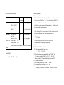
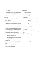
Table of Contents 1. Introduction 2. Safety note Smart SMD Tester USER’S MANUAL 3. Explanation of Controls and Indicators 3-1. Product Illustration 3-2. Push Buttons 3-3. LCD display 4. Specification MODEL: MS8910 4-1. General Feature 4-2. Electrical Specification 5. Testing Operation 5-1. Scanning Mode 5-2. Resistance Measurement 5-3. Capacitance Measurement 5-4. Diode Check 5-5. Continuity Check 6. Maintenance 6-1. Replacing The Battery 6-2. Cleaning 1. Introduction 2. Safety Note The Tester is a handheld and battery operated very convenient small Tool that is specially used to measuring SMD (Surface Mounting Device), there are Chip type resistor, Chip type capacitor and diode, for example. Moreover, the Tester have the continuity checking function The Tester is automatically identified the passive Component as has been indicated above. Therefore, the measurement are allowed by fully automatic detection. The Tester is designed to meet IEC1010-1 standard and Stipulation of 2-Poulation Grade. The Tester conform to the European Union’s following Requirement: CE regulation 89/336 (EMC Electromagnetic Compatibility) 。 The entire outer surface of the Tester case has been with thermo plastic elastomer, and the two testing pins has been gold-plated, so that it is reduce pin contact resistance and prevent to get rusty. This operating instruction covers information on safety and caution, so please read relevant information carefully and observe all the warming and note strictly. The following safety notes should be observed prior to using This Tester and any associated accessory. Although the Tester do not used to measuring DC/AC Voltage or Current, but there are situations where hazardous condition may be present. ● Inspect the Tester case before using. Do not use damaged device. ● Inspect the Pin Holder and Pin gold-plated state. ● Do not attempt use the Tester as tweezers to prevent the pin tip from damage. ● Do not apply external voltage between the two pins. ● Do not used in the environment with explosive gas, vapor, or dust. Caution Never use the Tester on alive circuits. 3. Explanation of Control and Indicators 3.1 Product Illustration 3.2. Push Buttons [1] “FUNC“ : it is the function select key that acts trigger. Use the Push Button as switch of Resistanc/Capacitance/Diode/Continuity. The Tester is have not Power Key. When install the 3V Lithium Battery, the Tester immediately power ON. Once powered on, the Tester will perform the Scanning Mode and then the ‘SCAN’ and ‘ - - - - ’ sign is displayed on the LCD. This is indicate the Tester is inter to the auto scanning mode and will be automatically identify the resistor, capacitor, diode and continuity measurement mode. The ‘FUNC’ Button is used to selecting some one measurement mode manually. [2] “HOLD” : Press “HOLD” Button to enter or exit the hold mode ① LCD ② “HOLD” Push Button ③ “FUNC” Push Button ④ Pin Holder ⑤ Test Pin (Gold-plated)(‘INPUT’ Terminal) ⑥ Test Pin (Gold-plated)(‘COM’ Terminal) ⑦ Battery cover In any measurement mode. This key is act with trigger. In the data hold mode, the Tester stop updating LCD, stored current measuring data and displayed the measured data, and then holding the data until press the “HOLD” key once again. Note: after auto power-OFF is active, pushing any of the push button can turn on the Tester again. 3-3. LCD Display 4. Specification 4-1. General Feature ● ● No. Indicator 1 SCAN 2 AUTO 3 Meaning Auto Scanning Mode Auto Ranging Data Hold ● ● ● ● ● ● ● ● ● ● 4 5 Diode checking Mode Continuity Checking Mode ` 6 7 8 numF MKΩ Capacitance Units(nF, uF, mF) Resistance Units(Ω, KΩ, MΩ) Low Battery Indicator ● ● ● ● 3000 count LCD display. Full automatic measurement: Auto scanning the Resistance/Capacitance/Diode. Function selection by one “FUNC” Push Button Data Hold function Continuity Checking function Over Load Indication ( ‘OL’) Low Battery Indication Power Supply: 3V Lithium Battery (CR2032) , 1pc Test Pins is Gold-Plated. Auto Power OFF. If the Tester is idle for more than 10 minutes, The Tester automatically turns the power off. Operating temperature & Humidity: 0 ~ 40℃(32 ~104 ℉) & < 80% RH Storage temperature & Humidity: -10 ~ 50℃ (14 ~ 122 ℉) & <70%RH Safety Class: IEC1010-1, CAT II EMC: According to CE regulation 89/336. Dimension (L x W x H) & Weight: 170 x 31 x 17mm, Approx. 48.6 g Environmental condition: (1)Indoor use; (2)Altitude up to 2000meter. 4-2. Electrical Specification Function Resistance 5. Testing Operation Range Best Resolution 300Ω/3KΩ/ 30KΩ/300K/3MΩ 0.1Ω ±(1%rdg+ 2dgt) ±(1.2%rdg+ 3dgt) 30MΩ Capacitance Accuracy 3nF/30nF/300nF/ 3uF/30uF/ 300uF/3mF/30mF 1pF ±(2%rdg+ 3dgt) ±(3%rdg+ 3dgt) Diode Check Open Voltage : 2.8V Testing Current : 2mA Continuity Check When the resistance is less than 30Ω, the Buzzer is sounded. In the Scanning Mode, when two pins are in touch with the object being measured, the measured value will be displayed on the LCD. Caution When measuring SMD device on the PCB, You must be Disconnect power and discharge all high- voltage Capacitors. 5-2. Resistance Measurement [1] Auto scanning Mode & Auto range: Accessory: 1. Spare Test Pin: 5-1, Scanning Mode When install the 3V Lithium Battery, the Tester immediately power ON. In this case, the ‘SCAN’ and ‘ - - - - ’ sign is displayed on the LCD. This is indicate the Tester is inter to the auto scanning mode and automatically identified the resistor, capacitor, diode and continuity ,and then enter to the corresponding measurement mode. 2 pcs 300.0Ω — 3.000MΩ [2] Selected Resistance measurement Mode by the‘FUNC“ key: The range is extended to 30 MΩ, i.e.300.0Ω — 30.00MΩ When over load, the ‘OL’ symbol will be displayed on the LCD. 5-3. Capacitance Measurement [1] Auto scanning & Auto range: 3.000nF — 300.0uF。 [2] Selected Capacitance Mode by the ‘FUNC’ key: The range is extended to 30.00mF, i.e. 3.000nF—30.00mF. Caution To avoid damage to the Meter or to the equipment under test, disconnect power and discharge all high-voltage capacitors before measurement capacitance. 5-4 Diode Check 6. Maintenance 6-1. Replacing The Battery When meter display , the battery must be replace to maintain normal operation. You can selecting the Scanning Mode or the Diode Mode by The ‘FUNC’ push button. ① Open the battery cover on the bottom case by screwdriver. ① Use the diode test mode to check diodes, transistors and other semiconductor device. In the diode test mode sends a current through the semiconductor junction, and the measure the voltage drop across the junction. A good silicon junction drop between 0.5V — 0.8V. ② Remove old battery and snap new one into battery holder ② For forward voltage drop reading on any semiconductor component, the test pin(connected to the ‘INPUT’ terminal) is in touch with the component anode and the another test pin is in touch with on the component cathode. The measured value show on the LCD. ③ Reverse the test pin and measure the voltage across the diode again. If diode is good, the display shows “OL”. If diode is shorted, the display shows 0 (zero) in both direction. If display shows “OL” in both direction, the diode is open. Note: Lithium Battery type: 3V CR2032 6-2. Cleaning The meter can be cleaned with soft clean cloth to remove any oil, grease or grim. Do not use liquid solvent or detergent. 5-5. Continuity Check May selecting Scanning Mode or Continuity Mode by ’FUNC’ push button. When the resistance reading is less than 30Ω, the buzzer generates 2KHz beep to indicate continuity. - END -