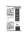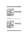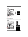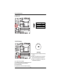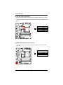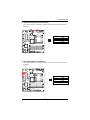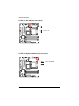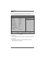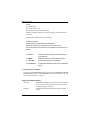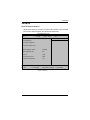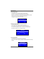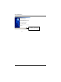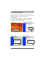
1
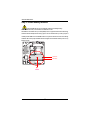
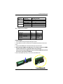
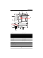
GA-8ICMT
Pentium Prescott 800 Motherboard
USER’S MANUAL
Pentium®Prescott Processor Motherboard
Rev. 1001
12ME-8ICMT-1001
English
GA-8ICMT Motherboard
Table of Content
Item Checklist ........................................................................................ 4
WARNING! ............................................................................................... 4
Chapter 1 Introduction ............................................................................ 5
Features Summary ...................................................................................... 5
GA-8ICMT Motherboard Layout .................................................................. 7
Chapter 2 Hardware Installation Process ............................................... 8
Step 1: Installing Processor and CPU Haet Sink ........................................ 9
Step1-1: Installing CPU ..................................................................................................... 9
Step1-2: Installing Heat Sink ........................................................................................... 10
Step 2: Install memory modules ................................................................ 11
Step 3: Install expansion cards ................................................................. 13
Step 4: Connect ribbon cables, cabinet wires, and power supply ........... 14
Step 4-1 : I/O Back Panel Introduction .......................................................................... 14
Step 4-2 :Connectors & Jumper Setting Introduction ................................................... 16
Chapter 3 BIOS Setup .......................................................................... 26
Main ........................................................................................................... 28
Advanced ................................................................................................... 31
Memory Configuration ..................................................................................................... 32
PCI Configuration ............................................................................................................. 33
I/O Device Configuration ................................................................................................. 35
Advanced Chipset Control ............................................................................................. 39
Security ...................................................................................................... 42
Server ......................................................................................................... 44
System Management ...................................................................................................... 45
Console Redirection ........................................................................................................ 46
Boot ............................................................................................................ 48
Exit ............................................................................................................. 49
2
Chapter 4 Technical Reference ............................................................ 52
Block Diagram ........................................................................................... 52
Chapter 5 Driver Installation .................................................................. 53
A.Intel Chipset Software Installation Utilities .................................................................. 53
B.Intel VGA Driver Installation ........................................................................................ 55
C.Intel LAN Driver Installation ....................................................................................... 56
D.Intel Pro Software Utility Installation .......................................................................... 57
E.Adapetc SATA RAID Driver Installation ...................................................................... 59
F.DirectX 9.0 Driver Installation ...................................................................................... 61
Chapter 6 Appendix .............................................................................. 62
Acronyms ....................................................................................................................... 62
3
English
Table of Content
English
GA-8ICMT Motherboard
Item Checklist
The GA-8ICMT motherboard
IDE (ATA100 ) cable x 1 / Floppy cable x 1
Serial ATA cable x 4
I/O Shield Kit
CD for motherboard driver & utility
GA-8ICMT user’s manual
WARNING!
Computer motherboards and expansion cards contain very delicate Integrated Circuit (IC) chips. To
protect them against damage from static electricity, you should follow some precautions whenever you
work on your computer.
1.
Unplug your computer when working on the inside.
2.
Use a grounded wrist strap before handling computer components. If you do not have
one, touch both of your hands to a safely grounded object or to a metal object, such as
the power supply case.
Hold components by the edges and try not touch the IC chips, leads or connectors, or
other components.
Place components on a grounded antistatic pad or on the bag that came with the
components whenever the components are separated from the system.
Ensure that the ATX power supply is switched off before you plug in or remove the ATX
3.
4.
5.
power connector on the motherboard.
Installing the motherboard to the chassis…
If the motherboard has mounting holes, but they don’t line up with the holes on the base and
there are no slots to attach the spacers, do not become alarmed you can still attach the spacers to
the mounting holes. Just cut the bottom portion of the spacers (the spacer may be a little hard to
cut off, so be careful of your hands). In this way you can still attach the motherboard to the base
without worrying about short circuits. Sometimes you may need to use the plastic springs to isolate
the screw from the motherboard PCB surface, because the circuit wire may be near by the hole. Be
careful, don’t let the screw contact any printed circuit write or parts on the PCB that are near the
fixing hole, otherwise it may damage the board or cause board malfunctioning.
4
Introduction
Chapter 1 Introduction
Features Summary
Form Factor
9.6” x 9.6” M ATX size form factor, 6 layers PCB.
CPU
Supports Intel® Pentium Prescot and Celeron processor
Intel® Prescott LGA 775 supports 533/800MHz FSB
Chipset
L2 cache on-die per processor from 1M
Intel® MCH E7221 Chipset
Memory
Intel® ICH6R
4 x DDRII socket up to 4 GB
Supports Dual Channel Un-buffered DDRII 400/533
Support 256MB, 512MB, and 1GB memory
I/O Control
Expansion Slots
Single-bit Errors Correction, Multiple-bit Errors Detection
ITE IT8712F-A Super I/O
Supports 2 PCI slots 32-Bit/33MHz (5V)
Supports 1 PCI-Express x1 slot
On-Board RAID
Supports 1 PCI-Express x8 slot
ICH6R
On-Board Peripherals
Supports SATA RAID 0,1
1 PATA IDE connector
1 Floppy port supports 2 FDD with 360K, 720K,1.2M, 1.44M
and 2.88M bytes.
2 PS/2 connectors
1 Parallel port supports Normal/EPP/ECP mode
1 Serial port (COM)
4 x USB 2.0
1 VGA connector
1 x LAN RJ45
Hardware Monitor
4 x SATA connectors
CPU/Power/System Fan Revolution Detect
CPU shutdown when overheat
System Voltage Detect
On-Board Graphic
On-Board LAN
Build in Intel MCH E7221 Chipset
Intel 82541PI Gigabit Ethernet
BIOS
Supports ASF 2.0to protect remote transactions
Phoenix BIOS on 4Mb flash RAM
5
English
GA-8ICMT Motherboard
Additional Features
PS/2 Mouse power on under Windows Operating System
External Modem wake up
Supports S1, S4, S5 under Windows Operating System
Wake on LAN (WOL)
AC Recovery
Supports Console Redirection
6
Introduction
GA-8ICMT Motherboard Layout
O
E
D
M
W
V
U
Y
T
A
L
B
LGA775
C
Q
R
S
N
K
X
J
HI F
P
G
A.
CPU
N.
F_USB1
B.
C.
Intel E7221
Intel ICH6R
O.
P.
REAR_FAN
DDRII 1
D.
E.
ITE IT8712F
Intel 82541PI
Q.
R.
DDRII 2
DDRII 3
F.
G.
SATA1
SATA2
S
T.
DDRII 4
PCI-E x1 (PCI-E x4 Slot)
H.
I.
SATA3
SATA4
U.
V.
PCI-E x8
PCI 1
J.
K.
FDD
IDE
W.
X.
PCI 2
ATX
L.
F_Panel
Y.
ATX12V
M.
System Fan
7
Hardware Installation Process
Chapter 2 Hardware Installation Process
To set up your computer, you must complete the following steps:
Step 1- Install the Central Processing Unit (CPU)
Step 2- Install memory modules
Step 3- Install expansion cards
Step 4- Connect ribbon cables, cabinet wires, and power supply
Step 5- Setup BIOS software
Step3
Step4
Step1
LGA775
Step 2
Step 4
Step 4
8
Step 4
English
GA-8ICMT Motherboard
Step 1: Installing Processor and CPU Haet Sink
Before installing the processor and cooling fan, adhere to the following cautions:
1. The processor will overheat without the heatsink and/or fan, resulting in permanent
irreparable damage.
2. Never force the processor into the socket.
3. Apply thermal grease on the processor before placing cooling fan.
4. Please make sure the CPU type is supported by the motherboard.
5. If you do not match the CPU socket Pin 1 and CPU cut edge well, it will cause improper
installation. Please change the insert orientation.
Step1-1: Installing CPU
Step 1 Gently lift the metal lever located on the CPU socket to the upper-right position.
Step 2 Remove the plastic covering on the CPU socket.
Step 3 Align the indented corner of the CPU with the triangle and gently insert the CPU into position.
(Grasping the CPU firmly between your thumb and forefinger, carefully place it into the socket
in a straight and downwards motion. Avoid twisting or bending motions that might cause
damage to the CPU during installation.)
Step 4 Once the CPU is properly inserted, please replace the plastic covering and push the metal
lever back into its original position.
Step 5 Close the lever, reverse step 1 & 2.
9
Hardware Installation Process
Step1-2: Installing Heat Sink
Male Push Pin
The top of Female Push Pin
Female Push Pin
Fig.1
Please apply heatsink paste on the surface of
the installed CPU.
Fig. 2
( to remove the heatsink, turning the push pin along
the direction of arrow; and reverse the previous
step to install the heat sink.)
Please note the direction of arrow sign on the male
push pin doesn't face inwards before installation.
(This instruction is only for Intel boxed fan)
Fig. 3
Place the heatsink on top the CPU and make
sure the push pins align to the pin hole on the
motherboard.Push down the push pins
diagonally.
Fig. 4
Please make sure the Male and Female push pin
are brought together. (for detailed installation
instructions, please refer to the heatsink installation
section of the user manual)
Fig. 5
Please check the back side of teh motherboard.
Make sure the push pin is seated firmly as the
picture shown. Installation completed.
Fig. 6
Attach the power connector of the heatsink to the
CPU fan header located on the motherboard.
10
English
GA-8ICMT Motherboard
Step 2: Install memory modules
Before installing the processor and heatsink, adhere to the following warning:
When DIMM LED is ON, do not install/remove DIMM from socket.
GA-8ICMT has 4 dual inline memory module (DIMM) socets. It supports the Dual Channel Technology.
The BIOS will automatically detects memory type and size. To install the memory module, just push it
vertically into the DIMM socket .The DIMM module can only fit in one direction due to the notch. Wrong
orientation will cause improper installation. Please change the insert orientation. Memory size can vary
between sockets.
LGA775
Channel A
Channel B
Notch
11
Hardware Installation Process
Table 1. Supported DIMM Module Type
Technology
256MB
512MB
1GB
Organization
8MB x 8 x 4 bks
16MB x 4 x 4bks
16MB x 8 x 4bks
32MB x 4 x 4bks
32MB x 8 x 4bks
64MB x 4 x 4bks
SDRAM Chips/DIMM
8
16
8
16
8
16
Table 2. DIMM Placement DDR2-400
DIMM Configuration
DIMM1
DIMM2
1
1
2
1
2
Empty
Empty
Empty
Empty
Empty
Empty
Empty
Single Rank
Single Rank
Dual Rank
Single Rank
Dual Rank
Single Rank
Dual Rank, 1 Single Rank
Dual Rank
Installation Step:
1. Unlock a DIMM socket by pressing the retaining clips outwards.
2. Aling a DIMM on the socket such that the notch on the DIMM exactly match the notches in the
socket.
3. Firmly insert the DIMMinto the socket until the retaining clips snap back in place.
4. When installing the DIMM into the DIMM socket, we recommend to populate one DIMM in
Channel A module and one in Channel B module for best performance.
Please note that each logical DIMM must be made of two identical DIMMs having the same
device size on each and the same DIMM size.
5. Reverse the installation steps when you wish to remove the DIMM module.
12
English
GA-8ICMT Motherboard
Step 3: Install expansion cards
1. Read the related expansion card’s instruction document before install the expansion card into
the computer.
2. Remove your server’s chassis cover, necessary screws and slot bracket from the computer.
3. Press the expansion card firmly into expansion slot in motherboard.
4. Be sure the metal contacts on the card are indeed seated in the slot.
5. Replace the screw to secure the slot bracket of the expansion card.
6. Replace your computer’s chassis cover.
7. Power on the computer, if necessary, setup BIOS utility of expansion card from BIOS.
8. Install related driver from the operating system.
13
Hardware Installation Process
Step 4: Connect ribbon cables, cabinet wires, and power
supply
Step 4-1 : I/O Back Panel Introduction
LGA775
14
English
GA-8ICMT Motherboard
PS/2 Keyboard and PS/2 Mouse Connector
To install a PS/2 port keyboard and mouse, plug the mouse to the upper port (green) and the keyboard
to the lower port (purple).
/
Parallel Port / Serial Port / VGA Port
This connector supports 1 standard COM port and 1 Parallel port. Device like printer can be
connected to Parallel port ; mouse and modem etc can be connected to Serial port.
LAN Port
The provided Internet connection is Gigabit Ethernet, providing data transfer speeds of 10/
100/1000Mbps.
USB Port
Before you connect your device(s) into USB connector(s), please make sure your device(s) such
as USB keyboard, mouse, scanner, zip, speaker...etc. have a standard USB interface.
Also make sure your OS supports USB controller. If your OS does not support USB controller,
please contact OS vendor for possible patch or driver updated. For more information please
contact your OS or device(s) vendors.
LAN LED Description
Name
Color
LAN
Green
Link/Activity Green
Condition
Description
ON
BLINK
LAN Link / no Access
LAN Access
10/100 LAN Green
OFF
ON
Idle
100Mbps connection
Speed
GbE LAN Yellow
Speed
Yellow
OFF
ON
10Mbps connection
1Gbps connection
Green
BLINK
ON
Port identification with 1Gbps connection
100Mbps connection
Green
-
BLINK
OFF
Port identification with 10 or 100Mbps connection
10Mbps connection
15
Connector Introduction
Step 4-2 :Connectors & Jumper Setting Introduction
Q
O
R
B
P
M
L
J
LGA775
S
T
I
N
H
G
A)
B)
C)
D)
E)
F)
G)
H)
I)
J)
K)
L)
E
K
D
C
A
F
ATX
ATX _12V
IDE
FDD
S_ATA1
S_ATA2
S_ATA3
S_ATA4
F_USB1
HDD_LED
BAT (Battery)
F_Panel1
M)
N)
O)
P)
Q)
R)
S)
T)
16
CPU_FAN
FRONT_FAN
REAR_FAN
SYS_FAN
PWR_JP1
PWR_JP2
PWR_JP3
JP3 (CMOS Clear Jumper)
English
GA-8ICMT Motherboard
A) ATX (ATX Power Connector)
12
24
1
13
LGA775
AC power cord should only be connected to
your power supply unit after ATX power cable
and other related devices are firmly connected
to the mainboard.
PIN No.
Definition
1
+3.3V
2
3
+3.3V
GND
4
5
+5V
GND
6
7
+5V
GND
8
9
POK
5VSB
10
11
+12V
+12V
12
13
+3.3V
+3.3V
14
15
-12V
GND
16
17
PSON
GND
18
19
GND
GND
20
21
-5V
+5V
22
23
+5V
+5V
24
GND
B ) ATX_12V( +12V Power Connector)
This connector (ATX +12V) is used only for
CPU1 Core Voltage.
1
LGA775
Pin No.
1
2
3
4
5
6
7
8
17
Definition
GND
GND
12V
12V
P12V_CPU1
P12V_CPU1
P12V_CPU0
P12V_CPU0
Connector Introduction
C ) IDE Connector
Please connect first harddisk to IDE1. The red stripe of the ribbon cable must be the same side with
the Pin1.
LGA775
1
39
2
40
D) FDD (Floppy Connector)
Please connect the floppy drive ribbon cables to FDD. It supports 360K,720K,1.2M,1.44M and
2.88Mbytes floppy disk types. The red stripe of the ribbon cable must be the same side with the
Pin1.
LGA775
18
2
34
1
33
English
GA-8ICMT Motherboard
E / F/ G / H ) S_ATA1/ 2/ 3/ 4 (Serial ATA Connectors)
You can connect the Serial ATA device to this connector, it provides you high speed transfer rates
(150MB/sec).
7
Pin No.
1
2
3
4
5
6
7
LGA775
1
Definition
GND
TXP
TXN
GND
RXN
RXP
GND
SATA_1
SATA_3 SATA_2
SATA_4
I )F_USB1 (Front USB Connector)
Be careful with the polarity of the front panel USB connector. Check the pin assignment while you
connect the front panel USB cable. Please contact your nearest dealer for optional front panel
USB cable.
9 10
1 2
LGA775
Pin No.
1
2
3
4
5
6
7
8
9
10
19
Definition
No Pin
USB over current
GND
GND
USB DX+
USB DY+
USB DXUSB DYPower
Power
English
GA-8ICMT Motherboard
J ) HDD_LED
1
LGA775
Pin No.
1
2
3
4
Definition
NC
HD_LED
HD_LED
NC
4
K ) BAT1 (Battery)
LGA775
CAUTION
Danger of explosion if battery is incorrectly
replaced.
Replace only with the same or equivalent
type recommended by the manufacturer.
If you want to erase CMOS...
1.Turn OFF the computer and unplug the power cord.
2.Remove the battery, wait for 30 second.
3.Re-install the battery.
4.Plug the power cord and turn ON the computer.
20
Dispose of used batteries according to the
manufacturer’s instructions.
Connector Introduction
L ) F_Panel1 (2X9 Pins Front Panel connector)
Please connect the power LED, PC speaker, reset switch and power switch of your chassis
front panel to the F_PANEL connector according to the pin assignment above.
LGA775
Pin No
1
Signal Name
HD+
Description
Hard Disk LED anode (+)
2
3
PDG
HD-
5VSB
Hard Disk LEDcathode(-)
4
5
PDY
GND
Power LED Signal
Ground
6
7
PW+
RST
Soft power connector anode (+)
Reset button
8
9
GND
VCC
Ground
+5V Standby power connector
10
11
SLP
IRRX
NC
No function
12
13
GND
GND
Ground
Ground
14
15
NC
IRTX
No connect
No function
16
17
VCC
GND
NC
Ground
18
CI
Case open signal
21
English
GA-8ICMT Motherboard
M ) CPU_FAN (CPU Fan Connector)
Please note, a proper installation of the CPU cooler is essential to prevent the CPU from running
under abnormal condition or damaged by overheating.The CPU fan connector supports Max. current
up to 1A .
Pin No.
1
2
3
4
1
Definition
GND
12V
Sense
Control
LGA775
N ) FRONT_FAN (Front System Fan Connector)
This connector allows you to link with the cooling fan on the system case to lower the system
temperature.
1
LGA775
22
Pin No.
1
2
3
4
Definition
GND
12V
Sense
Control
Connector Introduction
O ) REAR_FAN (Rear System Fan Connector)
This connector allows you to link with the cooling fan on the system case to lower the system
temperature.
Pin No.
1
2
3
4
LGA775
Definition
GND
12V
Sense
Control
P ) SYS_FAN (System Fan Connectors)
This connector allows you to link with the cooling fan on the system case to lower the system
temperature.
Pin No.
1
2
3
4
LGA775
23
Definition
GND
12V
Sense
Control
English
GA-8ICMT Motherboard
Q ) PWR_JP1 (Rear USB power source jumper)
1
1
1-2 close:Standby 5V (Default)
2-3 close: 5V
LGA775
R ) PWR_JP2 (Keyboard and Mouse power source jumper)
1
1-2 close: 5V (Default)
1
2-3 close:Standby 5V
LGA775
24
Jumper Setting
S ) PWR_JP3 (Front USB power source jumper)
1
1-2 close:Standby 5V (Default)
1
2-3 close: 5V
LGA775
T ) JP3 ( (Clear CMOS Function)
You may clear the CMOS data to its default values by this jumper.
Default value doesn’t include the “Shunter” to prevent from improper use this jumper.
To clear CMOS, temporarily short 1-2 pin.
LGA775
25
1
1-2 close: Normal
1
2-3 close: Clear CMOS
GA-8ICMT Motherboard
Chapter 3 BIOS Setup
BIOS Setup is an overview of the BIOS Setup Program. The program that allows users to modify the
basic system configuration. This type of information is stored in battery-backed CMOS RAM so that it
retains the Setup information when the power is turned off.
ENTERINGSETUP
Power ON the computer and press <F2> immediately will allow you to enter Setup.
CONTROLKEYS
<Ç>
Move to previous item
<È>
Move to next item
<Å>
Move to the item in the left hand
<Æ>
Move to the item in the right hand
<Esc>
Main Menu - Quit and not save changes into CMOS Status Page Setup Menu and
Option Page Setup Menu - Exit current page and return to Main Menu
<+/PgUp> Increase the numeric value or make changes
<-/PgDn>
Decrease the numeric value or make changes
<F1>
General help, only for Status Page Setup Menu and Option Page Setup Menu
<F2>
Reserved
<F3>
Reserved
<F4>
Reserved
<F6>
Reserved
<F7>
Reserved
<F8>
Reserved
<F9>
Load the Optimized Defaults
<F10>
Save all the CMOS changes, only for Main Menu
26
BIOS Setup
GETTINGHELP
Main Menu
The on-line description of the highlighted setup function is displayed at the bottom of the screen.
Status Page Setup Menu / Option Page Setup Menu
Press F1 to pop up a small help window that describes the appropriate keys to use and the
possible selections for the highlighted item. To exit the Help Window press <Esc>.
z
Main
z
Advanced
This setup page includes all the items in standard compatible BIOS.
This setup page includes all the items of AMI special enhanced features.
(ex: Auto detect fan and temperature status, automatically configure hard disk parameters.)
z
Security
Change, set, or disable password. It allows you to limit access the system and setup.
z
Server
z
Boot
Server additional features enabled/disabled setup menus.
This setup page include all the items of first boot function features.
z
Exit
There are five optionsin this selection: Exit Saving Changes, Exit Discarding Changes, Load
Optimal Defaults, Load Failsafe Defaults, and Discard Changes.
27
GA-8ICMT Motherboard
Main
Once you enter Phoenix BIOS Setup Utility, the Main Menu (Figure 1) will appear on the screen. Use
arrow keys to select among the items and press <Enter> to accept or enter the sub-menu.
PhoenixBIOS Setup Utility
Main
Advanced
Security
Server
Boot
Exit
System Time:
[00:13:12]
Item Specific Help
System Date:
[01/01/2005]
<Tab>, <Shift-Tab>, or
Lagecy Disktte A
[1.44MB 31/2]
<Enter> selects field.
Lagecy Disktte B
[Disabled]
Hard Disk Pre-Delay
[Disabled]
Primary IDE Master
[CD-ROM]
Primary IDE Slave
[None]
IDE Secondary/Master
[None]
IDE Secondary/Slave
[None]
Advanced Processor Options
Language
F1: Help
Esc: Exit
[Engliah (U.S)]
KL: Select Item
IJ: Select Menu
+ -: Change Values
F5: Setup Defaults
Enter: Select Sub-Menu F10: Save&Exit
Figure 1: Main
System Time
The time is calculated based on the 24-hour military time clock. Set the System Time (HH:MM:SS)
System Date
Set the System Date. Note that the “Day” automatically changed after you set the date.
(Weekend: DD: MM: YY) (YY: 1099~2099)
28
BIOS Setup
Legacy Diskette A/B
This category identifies the type of floppy disk drive A that has been installed in the computer.
Disabled
Disable this device.
360KB, 5 in.
3 1/2 inch AT-type high-density drive; 360K byte capacity
1.2MB, 31/2 in.
3 1/2 inch AT-type high-density drive; 1.2M byte capacity
720K, 31/2 in.
31/2 inch double-sided drive; 720K byte capacity
1.44M, 3 1/2 in.
3 1/2 inch double-sided drive; 1.44M byte capacity.
2.88M, 3
3 1/2 inch double-sided drive; 2.88M byte capacity.
1/4
1/2
in.
* Note: The 1.25MB,3
1/2
reference a 1024 byte/sector Japanese media format. The 1.25MB,31/2 diskette
requires 3-Mode floppy-disk drive.
Hard Disk Pre-Delay
This item provides function for user to add a delay before the first access of a hard disk by BIOS.
Some hard disks hang if accessed before they have initialized themselves. The delay ensures
the hard disk initialized after powering up, prior to being accessed.
Options
Disabled, 3 Seconds, 6 Seconds, 9 Seconds, 12 Seconds, 21 Seconds,
30Seconds. Default vaule is Disabled.
IDE Primary Master, Slave / Secondary Master, Slave, Parallel ATA
The category identifies the types of hard disk from drive C to F that has been installed in the computer.
There are two types: auto type, and manual type. Manual type is user-definable; Auto type which will
automatically detect HDD type.
Note that the specifications of your drive must match with the drive table. The hard disk will not work
properly if you enter improper information for this category.
If you select User Type, related information will be asked to enter to the following items. Enter the
information directly from the keyboard and press <Enter>. Such information should be provided in the
documentation form your hard disk vendor or the system manufacturer.
29
GA-8ICMT Motherboard
TYPE
1-39: Predefined types.
Users: Set parameters by User.
Auto: Set parameters automatically. (Default Vaules)
CD-ROM: Use for ATAPI CD-ROM drives or double click [Auto] to set all HDD parameters
automatically.
ATAPI Removable: Removable disk drive is installed here.
Multi-Sector Transfer
This field displays the information of Multi-Sector Transfer Mode.
Disabled: The data transfer from and to the device occurs one sector at a time.
Auto: The data transfer from and to the device occurs multiple sectors at a time if the device
supports it.
LBA Mode
This field shows if the device type in the specific IDE channel
support LBA Mode.
32-Bit I/O
Enable this function to max imize the IDE data transfer rate.
Transfer Mode
This field shows the information of Teansfer Mode.
Ultra DMA Mode
This filed displays the DMA mode of the device in the specific IDE
channel.
Advanced Processor Option
This category includes Processor Reset function and the information of CPU Speed, Processor ID,
Processor L2 Cache. Select ‘Yes’ on Processor Reset item, BIOS will clear historical processor
status and reset all processors on next boot.
Hyper Threading Technology
Enabled
Enables Hyper-Threading Technology Feature when using Windows
XP and Linux 2.4x operating systems that are optimized for HyperThreading technology. (Default value)
Disabled
Disables Hyper-Threading Technology when using other operating
systems.
30
BIOS Setup
Advanced
About This Section: Advanced
With this section, allowing user to configure your system for basic operation. User can change the
processor options, chipset configuration, PCI configuration and chipset control.
PhoenixBIOS Setup Utility
Main
Advanced
Security
Server
Memory Configuration
Boot
Exit
Item Specific Help
PCI Configuration
I/O Device Configuration
Advanced Chipset Control
Boot-time Diagnostic Screen
[Disabled]
Reset Configuration Data
[No]
NumLock
[Auto]
Memory/Processor Error
[Boot]
Multiprocessor Specification
[1.4]
F1: Help
Esc: Exit
KL: Select Item
IJ: Select Menu
+ -: Change Values
F5: Setup Defaults
Enter: Select Sub-Menu F10: Save&Exit
Figure 2: Advanced
31
GA-8ICMT Motherboard
Memory Configuration
PhoenixBIOS Setup Utility
Advanced
Memory Configuration
Item Specific Help
System Memory
KB
Extended Memory
KB
DIMM Group #1 Status
Not Installed
DIMM Group #2 Status
Not Installed
DIMM Group #3 Status
Not Installed
DIMM Group #4 Status
Not Installed
DIMM Group #5 Status
Not Installed
Memory Reset
[No]
Extended RAM Setup
[Disabled]
F1: Help
Esc: Exit
KL: Select Item
IJ: Select Menu
+ -: Change Values
F5: Setup Defaults
Enter: Select Sub-Menu F10: Save&Exit
Figure 2-1: Memory Configuration
System Memory/Extended Memory/DIMM Group 1,2,3,4,5 Status
These category is display-only which is determined by POST (Power On Self Test) of the BIOS.
Memory Reset
Yes
Select ‘Yes’, system will clear the memory error status.
No
Disable this function. (Default value)
Extend RAM Step
Enabled
Enable test extended memroy process.
Disabled
Disable this function. (Default value)
32
BIOS Setup
PCI Configuration
PhoenixBIOS Setup Utility
Advanced
PCI Configuration
Item Specific Help
Embedded Video Controller
Embedded NIC (Gbit #1)
PCI Slot 1 Option ROM
[Enabled]
PCI Slot 2 Option ROM
[Enabled]
PCI Slot 3 Option ROM
[Enabled]
PCI Slot 4 Option ROM
[Enabled]
F1: Help
Esc: Exit
+ -: Change Values
F5: Setup Defaults
Enter: Select Sub-Menu F10: Save&Exit
KL: Select Item
IJ: Select Menu
Figure 2-2: PCI Configuration
Embedded Video Controller
Onboard VGA Control
Enabled
Enable onboard VGA device. (Default value)
Disabled
Disable this function.
Pre-Allocated Memory Size
Select the amount of pre-allocated graphics memory for use by the Internal Graphics Device.
Options
1MB, 8MB. Default value is 8MB.
33
GA-8ICMT Motherboard
Embedded NIC #1
Onboard LAN Control
Enabled
Enable onboard LAN1 device. (Default value)
Disabled
Disable this function.
Option ROM Scan
Enabled
Enableing this item to initialize device expansion ROM.
Disabled
Disable this function. (Defualt value)
PCI Slot 1/2/3/4 Option ROM
Enabled
Enableing this item to initialize device expansion ROM.
(Defualt value)
Disabled
Disable this function.
34
BIOS Setup
I/O Device Configuration
PhoenixBIOS Setup Utility
Advanced
I/O Configuration
Serial port A:
Item Specific Help
[Disabled]
Base I/O address
[3F8]
Interrupt
[IRQ4]
Parallel port:
[Disabled]
Mode
[Bi-directional]
Base I/O address
[378]
PS/2 Mouse
[Enabled]
USB Controller
[Enabled]
USB 2.0 Controller
[Enabled]
Legacy USB Support
[Enabled]
Serial ATA:
[Enabled]
Native Mode operation
[Auto]
SATA Controller Mode Option
[Compatible]
F1: Help
Esc: Exit
KL: Select Item
IJ: Select Menu
+ -: Change Values
F5: Setup Defaults
Enter: Select Sub-Menu F10: Save&Exit
Figure 2-3: I/O Device Configuration
35
GA-8ICMT Motherboard
Serial Port A
This allows users to configure serial prot A by using this option.
Disabled
Disable the configuration.
Enabled
Enable the configuration (Default value)
Base I/O Address
3F8
Set IO address to 3F8. (Default value)
2F8
Set IO address to 2F8.
3E8
Set IO address to 3E8.
2E8
Set IO address to 2E8.
Interrupt
IRQ4
Set interrupt as IRQ4. (Default value)
IRQ3
Set interrupt as IRQ3.
Parallel Port
This allows users to configure parallel port by using this option.
Disabled
Disable the configuration.
Enabled
Enable the configuration. (Default value)
Mode
This option allows user to set Parallel Port transfer mode.
EPP
Using Parallel port as Enhanced Parallel Port.
Bi-directional
Use this setting to support bi-directional transfers on the parallel port.
(Default value)
ECP
Using Parallel port as Extended Capabilities Port.
Base I/O Address
378
Set IO address to 378
278
Set IO address to 278.
36
BIOS Setup
PS/2 Mouse
Set this option ‘Enabled’ to allow BIOS support for a PS/2 - type mouse.
Enabled
‘Enabled’ forces the PS/2 mouse port to be enabled regardless if a
mouse is present. (Default value)
Disabled
‘Disabled’ prevents any installed PS/2 mouse from functioning, but
frees up IRQ12.
USB Controller
This item allows users to enable or disable the USB device by setting item to the desired value.
Enabled
Enable USB controller. (Default value)
Options
Disbale this function.
USB 2.0 Controller
This item allows users to enable or disable the USB 2.0 device by setting item to the desired
value.
Enabled
Enable USB 2.0 controller. (Default value)
Options
Disbale this function.
Legacy USB Support
This option allows user to function support for legacy USB.
Enabled
Enables support for legacy USB (Default Value)
Disabled
Disables support for legacy USB
37
GA-8ICMT Motherboard
Serial ATA
Enabled
Enables on-board serial ATA function. (Default Value)
Disabled
Disables on-board serial ATA function.
` Native Mode Operation
This option allows user to set the native mode for Serial ATA function.
Auto
Auto detected. (Default value)
Serial ATA
Set Native mode to Serial ATA.
` SATA Controller Mode Option
Compatible Mode
SATA and PATA drives are auto-detected and placed in
Legacy mode. (Default value)
Enhanced (non-AHCI) Mode
SATA and PATA drives are auto-detected and placed in
Native mode.
Note: Pre-Win2000 operating system do not work in Enhanced mode.
` SATA AHCI Enable
Enabled
Set this item to enable SATA AHCI function for WinXP-SP1+IAA
driver supports AHCI mode.
Disabled
Disabled this function.
` SATA RAID Enable
Enabled
Enabled SATA RAID function.
Disabled
Disable this function.
38
BIOS Setup
Advanced Chipset Control
PhoenixBIOS Setup Utility
Advanced
Advanced Chipset Control
Item Specific Help
Enabled Multimedia Timer
[No]
ICH6 Root Port #1 Sub-Menu
PCI Device
Wake On LAN/PME
[Enabled]
Wake Up Ring
[Disabled]
Wake On RTC Alarm
[Disabled]
F1: Help
Esc: Exit
KL: Select Item
IJ: Select Menu
+ -: Change Values
F5: Setup Defaults
Enter: Select Sub-Menu F10: Save&Exit
Figure 2-4: Advanced Chipset Control
Enabled Multimedia Time
Yes
Enable Multimedia Timer Support.
No
Disable this function. (Default value)
ICH6 Root Port #1 Sub-Menu
Function for this category are for debugging the PCI Express Root Port #1.
Disabled
Port is always disabled.
Enabled
Port is always enabled.
Auto
Only enabled if card found. (Default value)
39
GA-8ICMT Motherboard
PCI Device
` PCI IRQ Line 1/2/3/4
When ACPI device cannot use IRQs already in use by ISA or EISA devices. Use ‘Auto
Select’ only if no ISA or EISA legacy cards are installed.
Auto Select
Auto selecting PCI IRQ lines. (Default value)
3,4,5,7,9,10,11,12,14,15
Selecting specify PCI IRQ lines.
Disabled
Disable this function.
Wake On LAN / PME
This option allow user to determine the action of the system when a LAN/PME wake up event
occurs.
Enabled
Enable Wake On LAN/PME. (Default value)
Disabled
Disable this function.
Note: This item must enabled if you’re running under Windows operating system.
Wake On Ring
This option allow user to determine the action of the system power is off and the modem is
ringing.
Enabled
Enable Wake On Ring. (Default value)
Disabled
Disable this function.
Note: This item must enabled if you’re running under Windows operating system.
Wake On RTC Alarm
You can set "RTC Alarm Resume" item to enabled and key in Data/time to power on
system.
Enabled
Enable alarm function to POWER ON system. (Default value)
Disabled
Disable this function.
Note: This item must enabled if you’re running under Windows operating system.
40
BIOS Setup
Boot -time Diagnostic
When this item is enabled, system will shows Diagnostic status when system boot.
Enabled
Enable Boot-time Diagnostic.
Disabled
Disable this function. (Default value)
Memory Processor Error
When Boot is selected, the system will attempt to boot after a memory or proocessor error
occured.
Boot
System attempts to boot if a memory or proocessor error cooured.
(Default value)
Halt
System will stop if an error is detected during power up.
Multiprocessor Specification
This option allows user to configure the multiprocessor(MP) specification revision level. Some
operating system will require 1.1 for compatibility reasons.
1.4
Support MPS Version 1.4 . (Default value)
1.1
Support M PS Version 1.1.
Reset Configuration Data
Yes
Reset all configuration data.
No
Do not make any changes. (Default value)
NumLock
This option allows user to select power-on state for NumLock.
On
Enable NumLock.
Off
Disable this function.
41
GA-8ICMT Motherboard
Security
PhoenixBIOS Setup Utility
Main
Advanced
Security
Server
User Password Is:
Clear
Supervisor Password Is:
Clear
Set User Password
[Enter]
Set Supervisor Password
[Enter]
Password on boot
[Disabled]
Fixed disk boot sector
[Disabled]
Diskette access
[Supervisor]
F1: Help
Esc: Exit
KL: Select Item
IJ: Select Menu
Boot
Exit
Item Specific Help
+ -: Change Values
F5: Setup Defaults
Enter: Select Sub-Menu F10: Save&Exit
Figure 3: Security
*
About This Section: Security
In this section, user can set either supervisor or user passwords, or both for different level of
password securities. In addition, user also can set the virus protection for boot sector.
Set Supervisor Password
You can install and change this options for the setup menus. Type the password up to 6
characters in lengh and press <Enter>. The password typed now will clear any previously
entered password from the CMOS memory. You will be asked to confirm the entered
password. Type the password again and press <Enter>. You may also press <Esc> to abort
the selection and not enter a specified password or press <Enter> key to disable this option.
42
BIOS Setup
Set User Password
You can only enter but do not have the right to change the options of the setup menus. When
you select this function, the following message will appear at the center of the screen to assist
you in creating a password.
Type the password up to 6 characters in lengh and press <Enter>. The password typed now
will clear any previously entered password from the CMOS memory. You will be asked to
confirm the entered password. Type the password again and press <Enter>. You may also
press <Esc> to abort the selection and not enter a specified password.
Password on boot
Password entering will be required when system on boot.
Enabled
Requries entering password when system on boot.
Disabled
Disable this function. (Default value)
Fixed disk boot sector
Write Protect
Write protects boot sector on harddisk to protect against virus.
Normal
Set the fixed disk boot sector at Normal state. (Default value)
Diskette access
Control access to diskette drives.
User
Requires user’s password to access floppy drives.
Supervisor
Requires supervisor’s password to access floppy drives. (Default value)
43
GA-8ICMT Motherboard
Server
PhoenixBIOS Setup Utility
Main
Advanced
Security
Server
System Management
Boot
Exit
Item Specific Help
Console Redirection
Assert NMI on SERR
[Enabled]
Post Error Pause
[Enabled]
AC-LINK
[Last State]
F1: Help
Esc: Exit
KL: Select Item
IJ: Select Menu
+ -: Change Values
F5: Setup Defaults
Enter: Select Sub-Menu F10: Save&Exit
Figure 4: Server
44
BIOS Setup
System Management
PhoenixBIOS Setup Utility
Server
System Managerment
Item Specific Help
BIOS Version:
XXXXXX
Board Part Number:
XXXXXX
Board Serial Number:
XXXXXX
System Part Number:
XXXXXX
System Serial Number:
XXXXXX
Chassis Part Number:
XXXXXX
Chassis Serial Number:
XXXXXX
F1: Help
Esc: Exit
KL: Select Item
IJ: Select Menu
+ -: Change Values
F5: Setup Defaults
Enter: Select Sub-Menu F10: Save&Exit
Figure 4-1: System Management
Server Management
This category allows user to view the server management features. Including information of
BIOS Version, Board Part/Serial Number, System Part/Serial Number, and Chassis
Part/Serial Number. All items in this menu cannot be modified in user’s mode. If any items
require changes, please consult your system supervisor.
45
GA-8ICMT Motherboard
Console Redirection
PhoenixBIOS Setup Utility
Server
Console Redirection
Item Specific Help
BIOS Redirection Port:
[Disabled]
ACPI Redirection Port
[Disabled]
Baud Rate
[19.2K]
Terminal Type
[PS ANSI]
Flow Control
[CTR/RTS]
F1: Help
Esc: Exit
KL: Select Item
IJ: Select Menu
+ -: Change Values
F5: Setup Defaults
Enter: Select Sub-Menu F10: Save&Exit
Figure 4-2: Console Redirection
BIOS Redirection Port
If this option is set to enabled, it will use a port on the motherboard.
Serial Port A
Use Serial Port A as he COM port address.
Disabled
Disable this function. (Default value)
ACPI Redirection Port
Select the serial port to use for ACPI Headless Console Redirection. If the item is set to ‘Disabled’,
system will completely disable ACPi Headless Console Redirection.
Serial Port A
Use Serial Port A as he COM port address.
Disabled
Disable this function. (Default value)
Baud Rate
This option allows user to set the specified baud rate.
Options
300, 1200, 2400, 9600, 19.2K, 38.4K, 57.6K, 115.2K.
46
BIOS Setup
Terminal Type
This option allows user to select the specified terminal type. This is defined by IEEE.
Options
VT100, VT100 8bit, PC-ANSI 7bit, VT100+, VT-UTF8
Flow Control
This option provide user to enable the flow control function.
None
Not supported.
XON/OFF
Software control.
CTS/RTS
Hardware control. (Default value)
Assert NMI on SERR
If thisoption is set to enabled, PCI bus system error (SERR) is enabled and is routed to NMI.
Enabled
Enable Assert NMI on SERR. (Default value)
Disabled
Disable this function.
Post Error Pause
If this item is set to enabled, the system will wai for user intervention on critical POST errors. If
this item is disabled, the system will boot with no inten=rvention if possible.
Enabled
Enable Post Error Pause. (Default value)
Disabled
Disable this function.
AC-LINK
This option provides user to set the mode of operation if an AC / power loss occurs.
Power On
System power state when AC cord is re-plugged.
Stay Off
Do not power on system when AC power is back.
Last State
Set system to the last sate when AC power is removed. Do not power on
system when AC power is back. (Default value)
47
GA-8ICMT Motherboard
Boot
PhoenixBIOS Setup Utility
Main
Advanced
Security
Server
Boot
CD-ROM Drive
Exit
Item Specific Help
+Removable Devices
+Hard Drive
IBA GE Slot 0A58 V1226
F1: Help
Esc: Exit
KL: Select Item
IJ: Select Menu
+ -: Change Values
F5: Setup Defaults
Enter: Select Sub-Menu F10: Save&Exit
Figure 5: Boot
*
About This Section: Boot
The “Boot” menu allows user to select among four possible types of boot devices listed
using the up and down arrow keys. By applying <+> and <Space> key, you can promote
devices and by using the <-> key, you can demote devices. Promotion or demotion of devices
alerts the priority that the system uses to search for boot device on system power on.
Boot Device Priority
` Removable Device / Hard Drive / CD-ROM Drive/
These three fields determines which type of device the system attempt to boot from after
PhoenixBIOS Post completed. Specifies the boot sequence from the available devices. If the
first device is not a bootable device, the system will seek for next available device.
48
BIOS Setup
Exit
PhoenixBIOS Setup Utility
Main
Advanced
Security
Server
Exit Saving Changes
Boot
Exit
Item Specific Help
Exit Discarding Changes
Load Setup Defaults
Discard Changes
Save Changes
F1: Help
Esc: Exit
KL: Select Item
IJ: Select Menu
+ -: Change Values
F5: Setup Defaults
Enter: Select Sub-Menu F10: Save&Exit
Figure 6: Exit
*
About This Section: Exit
Once you have changed all of the set values in the BIOS setup, you should save your chnages and
exit BIOS setup program. Select “Exit” from the menu bar, to display the following sub-menu.
Exit Saving Changes
Exit Discarding Changes
Load Settup Default
Discard Change
Save Changes
49
GA-8ICMT Motherboard
Exit Saving Changes
This option allows user to exit system setup with saving the changes.
Press <Enter> on this item to ask for the following confirmation message:
Pressing ‘Y’ to store all the present setting values tha user made in this time into CMOS.
Therefore, whenyou boot up your computer next time, the BIOS will
re-configure your system according data in CMOS.
Setup Confirmation
Load previous configuration now?
[Yes]
[No]
Exit Discarding Changes
This option allows user to exit system setup without changing any
previous settings values in CMOS. The previous selection remain in effect.
This will exit the Setup Utility and restart your compuetr when selecting this option.
Press <Enter> on this item to ask for confirmation message.
Setup Warning
Configuration has not been saved!!
Save before exiting
[Yes]
[No]
Load Settup Default
This option allows user to load default values for all setup items.
When you press <Enter> on this item, you will get a confirmation dialog box with a message
as below:
Setup Confirmation
Load previous configuration now?
[Yes]
[No]
50
BIOS Setup
Discard Changes
This option allows user to load previos values from CMOS for all setup item.
When you press <Enter> on this item, you will get a confirmation dialog box with a message
as below:
Setup Confirmation
Load previous configuration now?
[Yes]
[No]
Save Changes
This option allows user to save setup dat ato CMOS.
When you press <Enter> on this item, you will get a confirmation dialog box with a message
as below:
Setup Confirmation
Load previous configuration now?
[Yes]
[No]
Press [Yes] to save setup daya to CMOS.
51
Driver Installation
Revision
Chapter History
5 Driver Installation
A.
Intel Chipset Software Installation Utilities
Insert the driver CD-title that came with your motherboard into your CD-ROM driver, the driver
CD-title will auto start and show a series of Setup Wizard dialog boxes. If not, please double click the
CD-ROM device icon in "My computer", and execute the setup.exe.
Installation Procedures:
1. The CD auto run program starts, Double click on “Intel Chipset Software Installation Utilities” to
start the installation.
2. Then, a series of installation wizards appear. Follow up the wizards to install the drivers.
3.Setup completed, click “Finish” to restart your computer.
Setup Wizard
Auto Run windows
2.Click "Next".
1.Click "Intel Chipset Software
Installation Utility" item.
(2)
(1)
License Aggremment
Readme Information
4.Click "Next".
3.Click "Yes".
(3)
(4)
53
GA-8ICMT Motherboard
Installation Completed
5. Installation completed, Click
"Finish" to restart computer.
(5)
54
Driver Installation
B.
Intel VGA Driver Installation
Insert the driver CD-title that came with your motherboard into your CD-ROM driver, the driver
CD-title will auto start and show a series of Setup Wizard dialog boxes. If not, please double click the
CD-ROM device icon in "My computer", and execute the setup.exe.
Installation Procedures:
1. The CD auto run program starts, Double click on “Intel VGA Driver” to start the installation.
2. Then, a series of installation wizards appear. Follow up the wizards to install the drivers.
3.Setup completed, click “Finish” to restart your computer.
Intel E7221 Graphic Installer Software
Auto Run windows
2.Click "Next".
1. Click "Intel VGA Driver" item.
(2)
(1)
Installation Completed
License Aggrement
3. Read throgh ‘License
Agreement’ and click
4. Installation completed.
Click “Finish”.
"Yes".
(3)
(4)
55
GA-8ICMT Motherboard
C.
Intel LAN Driver Installation
Insert the driver CD-title that came with your motherboard into your CD-ROM driver, the driver
CD-title will auto start and show a series of Setup Wizard dialog boxes. If not, please double click the
CD-ROM device icon in "My computer", and execute the setup.exe.
Installation Procedures:
1. The CD auto run program starts, Double click on “Intel LAN Driver” to start the installation.
2. Select “Install Base Driver.
3. System starts to install the LAN Driver automatically.
Intel LAN Drivers
Auto Run windows
2.Click "Install Base Driver" item.
1.Click "Intel LAN Driver" item.
(2)
(1)
Installing automatically
(3)
56
Driver Installation
D.
Intel Pro Software Utility Installation
Insert the driver CD-title that came with your motherboard into your CD-ROM driver, the driver
CD-title will auto start and show the installation guide. If not, please double click the CD-ROM device
icon in "My computer", and execute the setup.exe.
Installation Procedures:
1. The CD auto run program starts, Double click on “Intel LAN Driver” to enter Intel Pro Network
Connections Installation program.
2. Select “Install Software”.
3. Then, a series of installation wizards appear. Follow up the wizards to install the drivers.
4.Setup completed, click “Finish” to restart your computer.
Install Software
Auto Run windows
2.Click "Install Software" item.
1.Click "Intel LAN Driver" item.
(1)
(2)
License Agreement
InsallShield Wizard
4.Select “ I accept the term in
the license agreement and
3.Click "Next".
click "Next".
57
GA-8ICMT Motherboard
Ready to Install the Program
Setup Type
5. Select Typical and click
"Next".
6.Click "Install".
(5)
(6)
Insallation Complete
7.Click "Finish".
(7)
58
Driver Installation
E.
Adapetc SATA RAID Driver Installation
Installation Procedures:
1. The CD auto run program starts, Double click on “Adapyec SATA RAID Driver” to start the
installation.
2. Double click “Driver” folder.
3. Refer to yor operating systsem, select the desired folder to install the RAID driver.
4. Copy the folder to a floppy diskette. When installing, insert the dsikette into floppy drive.
Note: User must enable “SATA RAID” function in the CMOS “I/O Device Configuration”
setup meun before installing Adaptec RAID driver.
Auto Run windows
SATA RAID Driver
1. Click Driver folder.
1. Click "Adaptec SATA RAID
Driver" item.
(2)
(1)
Operating System Selection
1. Click the folder.
Refer to yor operating systsem,
select the desired folder to install
the RAID driver.
(3)
(4)
59
GA-8ICMT Motherboard
Copy Files
5. Copy files to floppy disk.
(5)
60
Driver Installation
F.
DirectX 9.0 Driver Installation
Insert the driver CD-title that came with your motherboard into your CD-ROM driver, the driver
CD-title will auto start and show the installation guide. If not, please double click the CD-ROM device
icon in "My computer", and execute the setup.exe.
Installation Procedures:
1. The CD auto run program starts, Double click on “Directx9.0” to start the installation.
2. Then, a series of installation wizards appear. Follow up the wizards to install the drivers.
3.Setup completed, click “Finish” to restart your computer.
Auto Run windows
License Agreement
2.Select “I accept the
agreement and click "Next".
1.Click "DirectX 9.0 Driver" item
(2)
(1)
Starting Installaiton
Installaiton Wizard completed
4.Click "Finish" to complete
3. Click “Next” to start the
installation .
the installation.
(3)
(4)
61
GA-8ICMT Motherboard
Revision
Chapter History
6 Appendix
Acronyms
Acronyms
ACPI
Meaning
Advanced Configuration and Power Interface
APM
AGP
Advanced Power Management
Accelerated Graphics Port
AMR
ACR
Audio Modem Riser
Advanced Communications Riser
BBS
BIOS
BIOS Boot Specification
Basic Input / Output System
CPU
CMOS
Central Processing Unit
Complementary Metal Oxide Semiconductor
CRIMM
CNR
Continuity RIMM
Communication and Networking Riser
DMA
DMI
DIMM
Direct Memory Access
Desktop Management Interface
Dual Inline Memory Module
DRM
DRAM
Dual Retention Mechanism
Dynamic Random Access Memory
DDR
ECP
Double Data Rate
Extended Capabilities Port
ESCD
ECC
Extended System Configuration Data
Error Checking and Correcting
EMC
EPP
Electromagnetic Compatibility
Enhanced Parallel Port
ESD
FDD
Electrostatic Discharge
Floppy Disk Device
FSB
HDD
Front Side Bus
Hard Disk Device
IDE
IRQ
Integrated Dual Channel Enhanced
Interrupt Request
62
Appexdix
Acronyms
I/O
Meaning
Input / Output
IOAPIC
ISA
Input Output Advanced Programmable Input Controller
Industry Standard Architecture
LAN
LBA
Local Area Network
Logical Block Addressing
LED
MHz
Light Emitting Diode
Megahertz
MIDI
MTH
Musical Instrument Digital Interface
Memory Translator Hub
MPT
NIC
Memory Protocol Translator
Network Interface Card
OS
OEM
Operating System
Original Equipment Manufacturer
PAC
POST
PCI A.G.P. Controller
Power-On Self Test
PCI
RIMM
Peripheral Component Interconnect
Rambus in-line Memory Module
SCI
SECC
Special Circumstance Instructions
Single Edge Contact Cartridge
SRAM
SMP
Static Random Access Memory
Symmetric Multi-Processing
SMI
USB
System Management Interrupt
Universal Serial Bus
VID
Voltage ID
63
Driver Installation
Revision
Chapter History
5 Driver Installation
A.
Intel Chipset Software Installation Utilities
Insert the driver CD-title that came with your motherboard into your CD-ROM driver, the driver
CD-title will auto start and show a series of Setup Wizard dialog boxes. If not, please double click the
CD-ROM device icon in "My computer", and execute the setup.exe.
Installation Procedures:
1. The CD auto run program starts, Double click on “Intel Chipset Software Installation Utilities” to
start the installation.
2. Then, a series of installation wizards appear. Follow up the wizards to install the drivers.
3.Setup completed, click “Finish” to restart your computer.
Setup Wizard
Auto Run windows
2.Click "Next".
1.Click "Intel Chipset Software
Installation Utility" item.
(2)
(1)
License Aggremment
Readme Information
4.Click "Next".
3.Click "Yes".
(3)
(4)
55
GA-8ICMT Motherboard
Installation Completed
5. Installation completed, Click
"Finish" to restart computer.
(5)
56
Driver Installation
B.
Intel VGA Driver Installation
Insert the driver CD-title that came with your motherboard into your CD-ROM driver, the driver
CD-title will auto start and show a series of Setup Wizard dialog boxes. If not, please double click the
CD-ROM device icon in "My computer", and execute the setup.exe.
Installation Procedures:
1. The CD auto run program starts, Double click on “Intel VGA Driver” to start the installation.
2. Then, a series of installation wizards appear. Follow up the wizards to install the drivers.
3.Setup completed, click “Finish” to restart your computer.
Intel E7221 Graphic Installer Software
Auto Run windows
2.Click "Next".
1. Click "Intel VGA Driver" item.
(2)
(1)
Installation Completed
License Aggrement
3. Read throgh ‘License
Agreement’ and click
4. Installation completed.
Click “Finish”.
"Yes".
(3)
(4)
57
GA-8ICMT Motherboard
C.
Intel LAN Driver Installation
Insert the driver CD-title that came with your motherboard into your CD-ROM driver, the driver
CD-title will auto start and show a series of Setup Wizard dialog boxes. If not, please double click the
CD-ROM device icon in "My computer", and execute the setup.exe.
Installation Procedures:
1. The CD auto run program starts, Double click on “Intel LAN Driver” to start the installation.
2. Select “Install Base Driver.
3. System starts to install the LAN Driver automatically.
Intel LAN Drivers
Auto Run windows
2.Click "Install Base Driver" item.
1.Click "Intel LAN Driver" item.
(2)
(1)
Installing automatically
(3)
58
Driver Installation
D.
Intel Pro Software Utility Installation
Insert the driver CD-title that came with your motherboard into your CD-ROM driver, the driver
CD-title will auto start and show the installation guide. If not, please double click the CD-ROM device
icon in "My computer", and execute the setup.exe.
Installation Procedures:
1. The CD auto run program starts, Double click on “Intel LAN Driver” to enter Intel Pro Network
Connections Installation program.
2. Select “Install Software”.
3. Then, a series of installation wizards appear. Follow up the wizards to install the drivers.
4.Setup completed, click “Finish” to restart your computer.
Install Software
Auto Run windows
2.Click "Install Software" item.
1.Click "Intel LAN Driver" item.
(1)
(2)
License Agreement
InsallShield Wizard
4.Select “ I accept the term in
the license agreement and
3.Click "Next".
click "Next".
59
GA-8ICMT Motherboard
Ready to Install the Program
Setup Type
5. Select Typical and click
"Next".
6.Click "Install".
(5)
(6)
Insallation Complete
7.Click "Finish".
(7)
60
Driver Installation
E.
Adapetc SATA RAID Driver Installation
Installation Procedures:
1. The CD auto run program starts, Double click on “Adapyec SATA RAID Driver” to start the
installation.
2. Double click “Driver” folder.
3. Refer to yor operating systsem, select the desired folder to install the RAID driver.
4. Copy the folder to a floppy diskette. When installing, insert the dsikette into floppy drive.
Note: User must enable “SATA RAID” function in the CMOS “I/O Device Configuration”
setup meun before installing Adaptec RAID driver.
Auto Run windows
SATA RAID Driver
1. Click Driver folder.
1. Click "Adaptec SATA RAID
Driver" item.
(2)
(1)
Operating System Selection
1. Click the folder.
Refer to yor operating systsem,
select the desired folder to install
the RAID driver.
(3)
(4)
61
GA-8ICMT Motherboard
Copy Files
5. Copy files to floppy disk.
(5)
62
Driver Installation
F.
DirectX 9.0 Driver Installation
Insert the driver CD-title that came with your motherboard into your CD-ROM driver, the driver
CD-title will auto start and show the installation guide. If not, please double click the CD-ROM device
icon in "My computer", and execute the setup.exe.
Installation Procedures:
1. The CD auto run program starts, Double click on “Directx9.0” to start the installation.
2. Then, a series of installation wizards appear. Follow up the wizards to install the drivers.
3.Setup completed, click “Finish” to restart your computer.
Auto Run windows
License Agreement
2.Select “I accept the
agreement and click "Next".
1.Click "DirectX 9.0 Driver" item
(2)
(1)
Starting Installaiton
Installaiton Wizard completed
4.Click "Finish" to complete
3. Click “Next” to start the
installation .
the installation.
(3)
(4)
63
GA-8ICMT Motherboard
Revision
Chapter History
6 Appendix
Acronyms
Acronyms
ACPI
Meaning
Advanced Configuration and Power Interface
APM
AGP
Advanced Power Management
Accelerated Graphics Port
AMR
ACR
Audio Modem Riser
Advanced Communications Riser
BBS
BIOS
BIOS Boot Specification
Basic Input / Output System
CPU
CMOS
Central Processing Unit
Complementary Metal Oxide Semiconductor
CRIMM
CNR
Continuity RIMM
Communication and Networking Riser
DMA
DMI
DIMM
Direct Memory Access
Desktop Management Interface
Dual Inline Memory Module
DRM
DRAM
Dual Retention Mechanism
Dynamic Random Access Memory
DDR
ECP
Double Data Rate
Extended Capabilities Port
ESCD
ECC
Extended System Configuration Data
Error Checking and Correcting
EMC
EPP
Electromagnetic Compatibility
Enhanced Parallel Port
ESD
FDD
Electrostatic Discharge
Floppy Disk Device
FSB
HDD
Front Side Bus
Hard Disk Device
IDE
IRQ
Integrated Dual Channel Enhanced
Interrupt Request
64
Appexdix
Acronyms
I/O
Meaning
Input / Output
IOAPIC
ISA
Input Output Advanced Programmable Input Controller
Industry Standard Architecture
LAN
LBA
Local Area Network
Logical Block Addressing
LED
MHz
Light Emitting Diode
Megahertz
MIDI
MTH
Musical Instrument Digital Interface
Memory Translator Hub
MPT
NIC
Memory Protocol Translator
Network Interface Card
OS
OEM
Operating System
Original Equipment Manufacturer
PAC
POST
PCI A.G.P. Controller
Power-On Self Test
PCI
RIMM
Peripheral Component Interconnect
Rambus in-line Memory Module
SCI
SECC
Special Circumstance Instructions
Single Edge Contact Cartridge
SRAM
SMP
Static Random Access Memory
Symmetric Multi-Processing
SMI
USB
System Management Interrupt
Universal Serial Bus
VID
Voltage ID
65