1
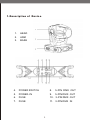
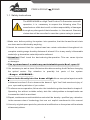
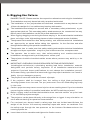
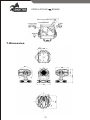
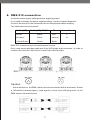
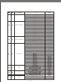
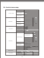
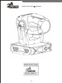
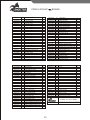
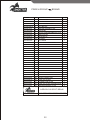
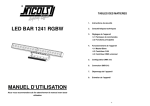
PROEL GROUP
BRAND
ARROW300B
MOVING HEAD
USER
S MANUAL
Sagitter.com
PROEL GROUP
BRAND
Table of content
1 Description of the device.................................................................. 3
1.1Safety Instructions ........................................................................................... 4
2 Preparation and Installation.............................................................. 5
2.1 Mounting........................................................................................................ 5
3 Open the box and checking............................................................... 6
fixture............................................................................
4 Rigging the fixture............................................................................6
4.1 Important........................................................................................................ 7
5 Operating determinations................................................................. 8
6 Rigging the fixture............................................................................ 9
7 Dimension..................................................................................... 10
connection.......................................................................
8 DMX-512 connection.......................................................................11
DMXrotocol........................................................................... .13.14
9 DMXrotocol...........................................................................12
10 Control menu map...........................................................................15
trait............................................................................
11 Performance trait............................................................................16
12 Maintenance and cleaning............................................................. 1 7
2
1.Description of Device
1.
2.
3.
HEAD
ARM
BASE
4.
POWER SWITCH
8.
5-PIN DMX OUT
5.
POWER-IN
9.
5-PIN DMX OUT
6.
FUSE
10. 3-PIN DMX OUT
7.
FUSE
11. 3-PIN DMX IN
3
PROEL GROUP
BRAND
1.1 Safety Instructions
The ARROW300B is a High-Tech Product.To Guarantee a smooth
!
operation, it is necessary to respect the following rules. The
manufacturer ofthis device will not take responsibility of damages
through any disregard of theinformation in this manual. Warranty
claims also will be cancelled in case the system casing is opened.
1.Make sure before putting the system into operation, that the fan and the air inlets
are clean and not blocked by anything.
2.It must be assured that the system-head can rotate unhindered throughtout his
complete rotating range.A safety distance of at least 0.5 m to any easily inflammable
material(e.g.decoration material)must be adhered.
3.Attention! Don't touch the device during the operation. This can cause injuries
or damages.
4.The system doesn't contain any maintainable parts.Don't open it!
5.It is necessary to wait at least 15minutes after disconnecting the AC before changing
the optical
carrier. Pay
attention
to
possibly
hot
parts
o f the
system.
--Danger of BURNING-6.Never look directly into the beam of light.Never use optical apertures with
a distance less than 0.5 m to observe the beam of light. You'll risk a serious injury of
your eyes and in particular of your retina.
7.To allow a secure operation,follow also the Installation guide described in chapter 2.
Operating the without suitable safety aids like safety cables or clamps/hooks can
increase the risk of an accident.
8.Repair, maintenance-and installation work shall be doneby qualified pay attention
to the common rules of technology that are not explicit mentioned in this manual.
9.Use only original spare parts.Any structural modification on the system will terminate
all warranty claims.
4
2.Preparation and Installation
2.1 Mounting
The ARROW300B is fully operational whether it hangs or is mounted to the wall.
It can also be operated while standing on the floor.Keep a safety distance of 0.5m
towards any easily in flammable materials (decoration etc.)
!
Pay attention to the regulations of:CE
The installtion shall be done by qualified staff only
For the various mounting positions of the ARROW300B (standing on the floor,
sideways or hanging)different accessories kits are available.Through this a safe
and minstallation is assured. You will find special connectors on the bottom
side of the system which are put to use here.In additioin the front side of the
system i s marked with(FRONT) as this is important for a even orientation during
installation.
5
PROEL GROUP
BRAND
3. Open the box and checking
Congratulati on s on choo sing our produ cts! Ple ase care fully read this instruc tion
ma nu al i n its ent irety and k eep it we ll for using refere nce. Thisma nual conta ined
a bou t the installa tion and the relative u sing informa tio n of this products. Please
accor din g to this manu al's rela tive spea king w hen u sing this equipm ent.
T his equipm ent was m ad e of new s tyle, high inten sity pla st i c. It fully sh ows the
mo dern ti m es l ight chara cter i stic with be a uty struct ure. A n d it w as m ade
accord in g to CE stand ard. F ully up the internati o nal stan dar d of D MX 512
agreem ent. Mast er or s lav e in ph ase con trol, ca n be u se d in l arge entertainment,
thea ter, perform ame and pla ying hall, etc.
T his pro duct u ses Ph i lips M SR GOLD3 0 0/2 fas t-fit elect r ical arc la mp. W hen
recei v ing this pro duct ple ase care f ully b ring and put; and ch eck whe ther this
equipm ent has b een dama ge d or not du ring transporta t ion. And ple ase also
ch eck the follow ing th ings was enclosed:
Signal cable ---------------1pcs
User
Safety string----------1pcs
manual-------------1pcs
Omega
holder---------2pcs
4. Safety instructions
Every person involved with installation and maintenance of this device have to:
-be qualified
-follow the instructions of this manual
CAUTION!
Be careful with your operations.
With a high voltage you can suffer
A dangerous electric shock when touching the wires!
This device has left our premises in absolutely perfect condition. In or der to
maintain this condition and to ensure a safe operation, it is absolutely necessary
for the user to follow t he safety instructions and warning notes written in this
manual.
6
4.1Important:
Th e manufactur er w ill n ot acce pt liabili ty f or an y resultin g damage d cause d b y
th e non-observanc e of th is manu a l o r an y unauthorize d modificatio n t o th e
device.
Pleas e consid er th at damage s cause d b y manu a l modification s to th e device
a re n ot subjecte d to warranty.
Nev er l et th e power-co rd com e in to connectin g wi th oth er cable s ! Hand l e the
pow er co rd an d a ll connection s wi th th e main s b y particul ar caution!
Mak e su re th at th e availab le voltag e is n ot high er tha n state d o n th e re ar panel.
Always plug in the power socket. Make sure that the power-switch is set to
off-position before you connect the device to the mains. The power plug has to be
accessable after installing the device.
Make sure that the power-cord is never crimped or damaged by sharp edges.
Check the device and the power-cord from time to time.
Always disconnect from the mains, when the device is not in use or before
cleaning it.
Only handle the power-cord by the plug. Never pull out the plug by tugging the
power cord.
This device falls under protection class I. Therefore it is essential to connect the
yellow/green conductor to earth.
The electric connection, repairs and servicing must be carried out by a
qualified employee.
Do not connect this device to a dimmer pack.
Do not switch the fixture on and off in short interval since this would reduce the
lamp's life.
During the initial start-up some smoke or smell may arise. This is a normal
process and does not mean that the device is defective.
Do not touch the device's housing by bare hands during its operation(housing
becomes hot)!
For replacement use lamps and fuses of same type and rating only.
CAUTION! EYEDAMAGES!
Avoiding looking directly into the light source
(Meant especially for epileptics)!
7
PROEL GROUP
BRAND
5. Operating deter minations
Th i s devic e is a moving hea d f or creatin g decorativ e effec t s an d i s designe d
for indo or u se only.
If t he devi ce h as be en expos ed to dras t ic temperatu re fluctuatio n. (e .g af ter
transportatio n), d o n ot swit ch it o n immediate ly. T h e arisi n g condensation
wa ter mig ht dama ge yo ur devic e. Lea ve t h e devi ce switch e d o ff un ti l it h as
reach ed roo m temperature.
Nev er r un t he devi ce witho ut lamp.
D o n ot sha ke t he devic e. Avo id bru te for c e wh e n installi n g o r operati n g t he
device.
Nev er lift t he fixtu re by holdi ng it at t he projector-hea d, as t he mechan ics m ay
be damage d. Alwa ys ho ld t he fixtu re at t he transp ort handles.
W hen choosing the installation-spot, please make sure that the device is not
exposed to heat, moisture or dust. There should not be any cables lying around.
You endanger your own and the safety of others!
Th e minimu m distan c e betwee n lig ht outp u t an d th e illuminate d surfa ce must
b e mo re tha n 1.5meters.
Ma ke su re th at th e are a belo w th e installatio n pla c e is blocke d whe n riggin g,
draggin g or servicin g th e fixture.
Always fix the fixture with an appropriate safety rope.
Fix the safety rope at the correct holes only.
Operation thefixture after having checked that the housing is firmly closed and
all screws are tightly fastened.
The lamp must never be ignited if the objective -lens or any housing-cover is
open, as discharge lamps may explode and emit a high ultraviolet radiation,
which may cause burns.
The maximum ambient temperature 40
cannot never be exceeded.
Operate the device only after having familiarized with its functions. Do not
permit operation by person not qualified for operating the device. M ost damage
are the result of unprofessional operation!
Please use the original packaging if the device is to be transported.!
Please consider that unauthorized modifications on the device are for bidden
due to safety reasons!
If this device will be operated in any way different from the one described in
this manual,the product may suffer damages and the guarantee becomes void.
Furthermore, any other operation may lead to dangers like short-circuit,b urns,
electric shock, burns due to ultraviolet radiation, lamp explosion, crash etc.
8
6. Rigging the fixture
DANGER TO LIFE Please consider the respective national norms during the installation!
The installation must only be carried out by an authorized dealer!
The installation of the projector has to be built and constructed in a way that can hold
10 times the weight for 1 hour without any harming deformation.
The installation must always be secured with a secondary safety attachment, e.g.an
appropriate catch net. This secondary safety attachment must be constructed in a way
that no part of the installation can fall if the main attachment fails.
When rigging, dragging or servicing the fixture staying in the area below the installation
place, on bridge, under high working place and other endangered area is forbidden.
The operator has to make sure that safety-relating and machine-technical installations
are approved by an expert before taking into operation for the first time and after
changes before taking into operation another time.
The operator has to make sure that safety-relating and machine-technical installations
are approved by an expert after every four year in the course of an acceptance test.
The operator has to make sure
that
safety-relating and
machine-technical
installations are approved by a skilled person once a year.
The projector should be installed outside areas where persons may walk by or be
seated.
IMPORTANT: OVERHEAD RIGGIG REQUIRES EXTENSIVE EXPERIENCE,
including(but not limited to) calculating working load limits, installation material
being used and periodic safety inspection of all installation material and the
projector. If you lack these qualifications, do not attempt the installation yourself,
but instead using a professional structural rigger.Improper installation can result in
bodily injury or damage to property.
The projector has to be installed out reach of people.
If the projector shall be lowered form the ceiling or high joists, professional
trussing systems have be used. The proj ector must never be fixed swinging freely
In the room.
Caution projectors may cause severe injuries when crashing d own!i f y ou h ave d oubts
concerning the safety of a possible installation, do NOT install the projector!
Before rigging make sure that the installation area can hold a minim um point load
of 10 times the projectors weight.
The projector can be placed directly on the stage floor or rigged in any orientation on
a trus without altering its operation characteristics.
For overhead use, always install a safety-rope that can hold at least 10 times the
weight of the fixture. You must only use safety-ropes with screw on carabines. Pull
the safety-rope through the two apertures on the bottom of the base and over the
trussing system etc.
Insert the end in the carabine and tighten the fixation screw.
9
PROEL GROUP
Mounting plate
7.Dimension
10
BRAND
8. DMX-512 connection
Verify the power supply settings before applying power!
If you wish to change the power supply settings, see the chapter Appendix.
Connect the fixture to the mains with the enclosed power cable and plug.
The earth has to be connected!
Cable(UE)
Cable(US)-208V
Pin
International
Brown
Black
Live
L
Liht blue
White
Neutral
N
Yellow/Green
Green
Earth
DMX-512 connection/connection between fixtures.
Only use a stereo shielded cable and 3-pin XLR-plugs and connectors in order to
connect the controller with fixture or one fixture with another.
Caution:
At the last fixture ,the DMX-cable has to be terminated with a terminator. Solder
a 120 resistor between signal (-) and signal (+) into a 3-pin XLR-plug and it in the
DMX-output of the last fixture.
11
PROEL GROUP
BRAND
9. DMXcontrol
SG ARR OW300B
DMX channel functions(Mode1=21channels Mode2=19channels)
Mode1 Mode2
1
1
2
3
2
PAN
Function
0-255
8BIT
0-255
TILT
0-255
8BIT
Speed pan/tilt movement
3
0-255
max to min speed
0-255
blackout by movement
226-235
blackout by all wheel changing
236-245
no function
6
4
Color wheel
0-12
Color1
13-25
Color2
26-38
Color3
39-51
Color4
52-64
Color5
65-77
Color6
Color7
78-90
91-103
Color8
104-116
Color9
117-127
Forwards rainbow effect from fast to slow
128-187
194-255
Open
0-9
Rot.gobo 1
10-19
Rot.gobo 2
20-29
Rot.gobo 2
30-39
Rot.gobo 4
40-49
Rot.gobo 5
50-59
Rot.gobo 6
60-69
Rot.gobo 7
70-79
Gobo 1 shake slow to fast
80-99
continue rotation
Gobo 2 shake slow to fast
100-119
Gobo 3 shake slow to fast
120-139
Gobo 4 shake slow to fast
140-159
Gobo 5 shake slow to fast
160-179
Gobo 6 shake slow to fast
180-199
Gobo 7 shake slow to fast
Rot.gobo wheel cont. rotation slow to fast
8
9
10
11
6
7
8
9
Gobo rotation
Cyan
188-193
Backwards rainbow effect from slow to fast
Rotating gobos index,
5
246-255
Open/white
No rotation
7
DMX Value
PAN 16BIT
TILT 16BIT
4
5
Name
200-219
220-255
Gobo indexing
0-127
Forwards gobo rotation from fast to slow
128-187
No rotation
Backwards gobo rotation from slow to fast
194-255
188-193
Cyan(0-whita,255-100% Cyan)
0-255
Magenta
Magenta(0-whita,255-100% magenta)
0-255
Yellow
Yellow(0-white,255-100% Yellow)
0-255
12
12
13
14
10
11
12
Speed Of CMY
And Dimmer
Speed Fast Slow
0-255
No Function
0-15
CNY abd color wheel
3 facet rotating prism
Macro 1
16-31
Macro 2
32-47
Macro 3
48-63
Macro 4
64-79
Macro 5
80-95
Macro 6
96-111
Macro 7
112-127
Macro 8
128-143
Macro 9
144-159
Macro 10
160-175
Macro 11
176-191
Macro 12
192-207
Macro 13
208-223
Macro 14
224-239
Macro 15
240-255
closed
0-31
Zoom
32-63
Forwards from fast to slow
64-155
No rotation
156-163
Backwards rotation from slow to fast
164-255
No Function
15
16
17
18
13
14
15
16
Iris
Focus
Macro 1
16-31
Macro 2
32-47
Macro 3
48-63
Macro 4
64-79
Macro 5
80-95
Macro 6
96-111
Macro 7
112-127
Macro 8
128-143
Macro 9
144-159
Macro 10
160-175
Macro 11
176-191
Macro 12
192-207
Macro 13
208-223
Macro 14
224-239
Macro 15
Frost 0-100%
240-255
240-255
Pulse opening fast to slow
192-223
Pulse closing slow to fast
224-254
Max. Frost
Max. diameter to Min. diameter
255
0-191
Pulse opening fast to slow
192-223
Pulse closing slow to fast
224-255
Effect Scene
Frost
0-15
Continuous adjustment from near to far
0-255
Shutter closed
0-31
No function (shutter open )
32-63
13
PROEL GROUP
BRAND
Strobe effest slow to fast
19
20
21
17
18
19
Shutter
Dimmer
Reset
64-95
No function(shutter open)
96-127
Pulse-effect in seqence
128-159
No function(shutter open)
160-191
Random strobe effect slow to fast
192-223
No function(shutter open)
Intensity 0 to 100%
224-255
Colour change normal
0-20
Colour change linear
20-39
No function
40-59
Lamp switch off
60-79
All motor reset
80-84
Scan motor reset
85-87
Colors motor reset
88-90
Gobo motor reset
91-93
Shutter & Dimmer motor reset
94-96
Other motor reset
97-99
Internal program1
100-119
Internal program2
120-139
Internal program3
140-159
Internal program4
160-179
Internal program5
180-199
Internal program6
200-219
Internal program7
220-239
Lamp on
240-255
14
10. Control menu map
Set Dmx Address
A001-AXXX
Value Display
PAN Moving
Master
Function Mode
Auto Program
Alone
OFF
Master
Music Control
Alone
OFF
Time info
Information
Temp. Info
Current time
ON/OFF
Total Run Time
ON/OFF
Lamp Run Time
ON/OFF
Clear Fixture Time
Base Temp
ON/OFF
Near Lamp Temp
ON/OFF
ON/OFF
Logo
Product Info.
Unit Model. VerXX
Company WEB
Lamp control
Switch lamp
ON/OFF
Power on light
ON/OFF
Light by DMX
ON/OFF
Lamp on delay
05M
Switch Lamp Half
ON/OFF
Lamp Half Time
Xxs
Addr.Via DMX
ON/OFF
Close
No DMX Status
DMX Mode
Auto
Music
Status Settings
Personality
Hold
Pan Reverse
ON/OFF
Tilt Reverse
ON/OFF
Lamp optimization
ON/OFF
Feedback
ON/OFF
Mic Sensitivity
70%,0-99%
Mode1/Mode2
Auto Fans Speed
Fans Control
High Fans Speed
Low Fans Speed
Display Set
Dis Close Time
Temperature C/F
Celsius/Fahrenheit
Language choose
English
Reset Default
Reset Function
Reset All
Reset Gobo
Test Channel
Effect Adjust
Regulate Value
15
ON/OFF
Reset Pan/Tilt
Reset Pins
PAN
05M,02-59M
Reset Color
Reset Else
xxx
PAN=xxx
__Password__
Password=XXX
PAN
PAN=XXX
PROEL GROUP
BRAND
11. Performance trait
1. Scan: Pan540 , Tilt260 . S can sp eed a d justable. S can fo llowing w ith s h utter.
Fixture could auto reset.
2. Color Wheel : open white+5collors, Speed variable double way rainbow effect.
Color location/ color random optional.
CMY System: linearIty: spead ajustional.
Gobo wheel:7rotaion gobos+open.
3. Normal triple prism system.
4. Zoom and focus system.
5. 22DMX Chs.
6. Frost :Linearity.
7. lris :Linearity adjust,pulse variation.
8. Strobe : two motor strobe,synchronous,non - synchronous , random strobe effect.
9. Blue/white LCD display graphic
Each DMX Value displayable
Monitor could ON/OF when return on
Show fixture lamp use time
Lamp ON/OF when return on
Half power energy saving function
Remote ON by DMX
Protection function: 5-60 minutes adjustable, PI No signal, fixture status keep
reset status,AUTO Play procedure,sound control status.
16
12.Maintenance and cleaning
It is absolutely essential that the fixture is kept clean and without dust. Dirt
and smoke - fluid residues must not be covered on or within the fixture.
Otherwise, the fixtures light output will be significantly reduced. Regular
cleaning will not onlyen sure the maximum light-output, but will also allow the
fixture to function reliably throughout its life.A soft lint-free cloth moistened.
With any good glass cleaning fluid is recommended, under no circumstance
of alcohol or solvents be used!
DANG ER :Disconnect from the mains before starting any maintenance work.
The front objective lens will require weekly cleaning as smoke-fluid tends to
building up residues,reducing the light-output very quickly. The cooling -fans
should be cleaned monthly.
The gobos may be cleaned with a soft brush.the interior of the fixture should
be cleaned at least annually usinga vacuum-cleaner or an air-jet.
The dichroic colour-filters,the gobo-wheel and the internal lenses should be
cleaned monthly.
to ensure a proper function of the gobo-wheel,we recom mend lubrication in
six month intervals.The quantity of oil must not be excessive in order to avoid
that oil runs out when the gobo-wheel rotates.
There are no serviceable parts inside the device except for the lam pand the
fuss. Please refer to the instructionsunder
Fitting/Exchanging the lamp .
Main tenance and service operations are only to be carried out by authorze
dealers.
Replacing the fuse
If the lamp bums out,the fuse might of fails might fuse, too. Only replace the
fuse by of same type and rating. Before replacing the fuse, unplug mains lead.
17
PROEL GROUP
18
BRAND
19
PROEL GROUP
BRAND
POS.
DESCRIPTION
N.PCS
SGVP00034
28
PRISM BELT
1
SGFP00037
1
FRONT COVER
1
SGVL00043
29
3 FACES PRISM
1
SGVL00042
2
FRONT GLASS
1
SGGM00030
30
PRISM HOLDER
1
SGTA00041
3
SPACER H50
4
SGTA00064
31
MAGNET
1
SG013-003
4
FRONT PLATE
1
SG013-004
32
LENS HOLDER PALTE
1
SGEE00030
5
PCB MOTORS
1
SGVL00040
33
STATIC ZOOM LENS
1
SG013-013
6
STOP LENS PLATE
1
SG013-009
34
LENS HOLDER RING
1
SGVL00041
7
BEAM LENS
1
SG013-010
35
LENS HOLDER
1
SG013-002
8
LENS HOLDER
1
SGVP00035
36
PRISM GEAR
1
SG001-043
9
FRONT COVER LAATE
2
SG010-07
37
PRISM HOLDER PLATE
1
SGEE00031
10
PCB SENSOR
3
SGMO00031
38
MOTOR 25 SH 16
1
SGVP00041
11
BELT PULLEY
1
SGMO00032
39
MOTRO 20 SH 16
4
SGVP00030
12
FOCUS BELT
1
SGGM00031
40
FROST PLATE
1
SG013-005
13
BELT HOLDER PLATE
1
SGGM00032
41
RIGHT STROSO PLATE
1
SGVP00031
14
FOCUS GEAR
1
SGGM00033
42
LEFT STROSO PLATE
1
SGMO00030
15
MOTOR 33 SH 16
2
SGGM00034
43
COLOR WHEEL
1
SG013-080
16
REINFORCEMENT SIDE PLATE
1
SGTA00065
44
SPACER H34
3
SGCM00010
17
SPRING CAMLOCK
8
SG010-081
45
MODLE HOLDER PLATE
1
SGVP00032
18
FOCUS GUIDE
1
SGTA00066
46
SPACER H38
2
SG013-011
19
STOP BELT PLATE
1
SG013-081
47
GOBOS PLKET HOLDER PLATE
1
EE00038
20
MOTORS PCB
2
SGGM00047
48
GOBOS POKET
1
SG013-29
21
MOTORS HOLDER PLATE
1
SG013-37
49
IRIS HOLDER PLATE
1
SGVP00033
22
PRISM GEAR
1
SG013-33
50
FIXING PLATE
1
SGTA00062
23
GEAR FLANGE
1
SGTA00067
51
SPACER H17
2
SG013-005
24
REINFORCEMENT SIDE PLATE
1
SGEE00032
52
PCS CONNECTION
1
SGTA00063
25
PRISM BELT PULLY
1
SGGM00035
53
GOBO HOLDER
7
SGMO00038
26
FAN
1
SGVP00038
54
GOGOS WHEEL GEAR
1
SGTA00040
27
COUNTERBALANCE
1
SGMO00033
55
MOTOR 33 SH 40
1
SGVP00037
56
GOBOS WHEEL MOTOR GEAR
1
SG013-047
84
REFECTOR HOLDER PLATE
1
SGTA00066
57
GOBO MAGNET
1
SGGM00044
85
GRID
2
SGGM00036
58
GOBOS WHEEL
1
SGEE00035
86
TEMPERATURE SENSOR
1
SG013-039
59
IRIS MOVEMENT PLATE
1
SG013-048
87
RIGHT REAR PLATE
1
SGTA00069
60
IRIS MOVEMENT FLANGE
1
SGMO00035
88
ATFAN
1
SGEE00033
61
PCB SENSOR
1
SG013-049
89
AIR CONVEYORS
2
SGGM00037
62
IRIS
1
SGTA00072
90
SPACER H20
4
SGEE00034
63
PCS DOUBLE SENSOR
1
SG013-050
91
REFLECTOR HOLDER
1
SG013-039
64
COLOR CHANGER PLATE
1
SGVL00045
92
REFLECTOR
1
SG013-040
65
SENSOR HOLDER PLATE
1
SG013-051
93
LEFT REAR PLATE
1
SGMO00034
66
MOTOR 20 SH 28
4
SG013-052
94
AIR CONVEYORS
1
SGVP00038
67
COLOR CHANGER BELT
4
SGE00030
95
THERMIC
1
SGVP00039
68
COLOR CHANGER GEAR
4
SG013-053
96
FIXING GUIDE PLATE
2
SGVP00041
69
COLOR CHANGER PULLER
4
SG013-054
97
REAR HOLDER FRAME
1
SG013-041
70
BELT FIXING PLATE
4
SGLP125
98
300 LOK-IT LAMP
1
SGGM00038
71
RIGHT MAGENTA FILTER
1
SG013-055
99
LAMP HOLDER PLATE
1
SGGM00039
72
RIGHT CYAN FILTER
1
SGPL03
100
LAMP HOLDER
1
SGGM00040
73
RIGHT YELLOW FLITER
1
SG013-056
101
REAR HAMP HOLDER PLATE
1
SG013-042
74
RIGHT DIMMER PLATE
1
SG013-057
102
REAR COVER
1
SGGM00041
75
LEFT MAGENTA FILTER
1
SGGM00045
103
LOWER BODY COVER
1
SGGM00042
76
LEFT CYAN FILTER
1
SGFP00035
104
1
SGGM00043
77
LEFT YELLOW FILTER
1
UPPER BODY COVER
Fixture
SG013-043
78
LEFT DIMMER PLATE
1
SGTA00071
79
SPACER H28
4
SG013-044
80
COLOR CHANGER HOLDER PLATE
1
SG013-045
81
SENSOR HOLDER PLATE
1
SG013-046
82
COLOR CHANGER COVER PLAE
1
SGVL00044
83
HEAT FILTER
1
CODE
ARROW 300 SPOT BEAM
Date
20
30/08/2010
Do not copy this drawing wihtout the auth orization of Sagitter R&D Italy
21
PROEL GROUP
CODE
BRAND
POS. DESCRIPTION
N.PCS
SGFP00036
1
YOKE COVER
2
SGEE00036
2
PCB ENCOER SENSOR
1
SG013-058
3
PCB HOLDER PLATE
1
SGMO00036
4
TILT MOTOR
1
SG031-059
5
MOTOR HOLDER PLATE
1
SGVP00042
6
ENCODER
1
SG013-030
7
RIGHT REINFORCEMENT PLATE
1
SGVP00043
8
BELT PULLEY
2
SGTA00073
9
SPACERH15
2
SGVP00044
10
TILTBELT
1
SGVP00045
11
TILT GEAR
1
SGTA00074
12
STOP BEARING FLANGE
2
SG013-022
13
RIGHT YOKE COVER FIXING
2
SG013-019
14
REAR YOKE PLATE
1
SGVP00046
15
BEARING
2
SGTA00075
16
BEARING HOLDER
2
SGTA00076
17
TILT ROTATING SHAFT
1
SGTA00082
18
TILT ROTATING SHAFT
1
SG013-023
19
LEFT YOKE COVER FIXING
2
SG013-021
20
YOKE PLATE
1
SG013-031
21
LEFT REINFORCEMENT PLATE
1
SGTA00077
22
BEARING SPACER
1
SG013-060
23
RESET PLATE
1
SGEE00037
24
PCB SENSOR
1
SG013-061
25
TILT LOCK SHAFT HOLERPLATE
1
SGTA00078
26
TILT LOCK SHAFT
1
SGVM00106
27
ROTARYDIAL
2
SGAB00010
28
IGNITOR
1
SG013-020
29
FRONT YOKE PLATE
1
SGTA00079
30
PAN LOCK SHAFT
1
SG013-062
31
LOWER YOKE PLATE
1
SG013-063
32
PAN LOCK SHAF HOLDER PLATE
1
SG013-064
33
REINFORCEMENT PLATE
2
Fixture
ARROW 300 SPOT BEAM
Date
30/08/2010
Do not copy this drawing wihtout the auth orization of Sagitter R&D Italy
22
23
PROEL GROUP
CODE
BRAND
POS. DESCRIPTION
N.PCS
SGTA00060
1
HANIF TUBF
2
SGFP00043
2
HANDLE
2
SGFP00045
3
BASE SIDE COVER
2
SGMO00037
4
FAN
2
SG013-065
5
BASE PLATE
1
SG013-025
6
BASE FRONT PLATE
2
SG013-023
7
CONNECTOR HOLER PLATE
1
SGGM00018
8
BATTTERY HOLER
1
SGBA00001
9
LITHIUM BATTERY
1
SCH99/033C
10
XLR3/XLR5 M/F DMXPCB
1
SGEI00031
11
FUSE HOLDER
2
SGEI00032
12
SWITCH
1
SGEI00033
13
SKINTOP PG11
1
SGFP00044
14
BASE FRONT COVER
1
SG013-066
15
BALLAST HOLDER PLATE
1
SGAB00011
16
BALLAST 300W
2
SG013-067
17
BASE COVER PLATE
2
SG013-068
18
BASE REINFORCEMENT PLATE
2
SG013-069
19
REINFORCEMENT PLATE
1
SG013-076
20
PAN SHAFT HOLDER PLATE
1
SGEE00040
21
PCB SENSOR
1
SGTA00080
PAN MOVEMENT PLATE
2
SG013-070
22
23
PAN RESET PLATE
1
SGTA00081
24
SPACER FLANGE
1
SGVP00047
25
PAN GEAR
1
SGGM00046
26
BEARINGS ASSEMBLY
1
SGTA00082
27
BEARING FLANGE
1
SG031-071
28
PAN RESET PLATE
1
SGVP00048
29
PAN BELT
1
SGVP00048
30
ENCODER
1
SG013-072
31
SENSOR HOLDER PLATE
1
SGEE00036
32
PCB ENCODER SENSOR
1
SGMO00038
33
PAN MOTOR SH 30
1
SGEE00041
34
POWER PCB
1
SGVR00002
35
RECEPTACLE COVER
6
SGVP00001
36
RECEPTACLE
6
SG013-073
37
LOWER BASE COVER PLATE
1
SG013-074
38
PCB HOLDER PLATE
1
SG013-074
39
PCB HOLDER PLATE
1
SG013-080
40
ROTARY DIAL HOLDER PLATE
1
SG013-026
41
DISPLAY HOLDER PLATE
1
SGVM00101
42
ROTARY DIAL
1
SG013-075
43
PCB HOLDER PLATE
1
SGEE00043
44
PAN TILT PCB
1
SGGO00011
45
FOOT
4
Fixture
ARROW 300 SPOT BEAM
24
PROEL S.p.A
(World Headquarters-Factory)
Via alla Ruenia,37/43
64027 Sant Omero(TE)-ITALY
Tel.+39 0861 81241
Fax+39 0861 887862
Sagitter.com