1
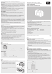
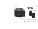
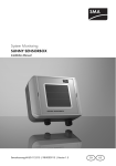
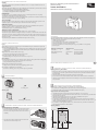
Information on this Manual
Validity
This manual is valid for the Sunny SensorBox with firmware version 1.51 or higher and hardware version C1.
Target Audience
This manual is intended for skilled persons. Only qualified personnel are allowed to perform the tasks set forth in
this manual. Skilled persons must have the following qualifications:
• Training in the installation and commissioning of electrical devices
• Knowledge of all applicable standards and guidelines
Device for determining environmental data for
plant monitoring
SUNNY SENSORBOX
Quick Reference Guide for Commissioning
Intended Use
For safety reasons, it is not permitted to modify the product or install components that are not explicitly
recommended or distributed by SMA Solar Technology AG.
Only use the Sunny SensorBox in accordance with the information provided in the enclosed documentation. Any
other use can result in personal injury or property damage.
Sunny SensorBox
The Sunny SensorBox is a device designed to provide sensor data for SMA communication products via the
RS485-Power Injector or the SMA Power Injector with Bluetooth® Wireless Technology.
RS485-Power Injector
The Sunny SensorBox is integrated into the RS485 communication bus via the RS485-Power Injector. The
RS485-Power Injector serves as a voltage supply for the Sunny SensorBox.
The RS485-Power Injector is only suitable for indoor mounting.
SMA Power Injector with Bluetooth
The SMA Power Injector with Bluetooth supplies voltage to max. 1 Sunny SensorBox.
The SMA Power Injector withBluetooth integrates the Sunny SensorBox in an SMA Bluetooth network and sends
measurements and various operating parameters from the Sunny SensorBox to SMA communication products in
your plant. You can also use the SMA Power Injector with Bluetooth to bridge dead zones in the SMA Bluetooth
network of your plant.
The SMA Power Injector withBluetooth is intended exclusively for indoor mounting.
Safety Precautions
Injuries
Lethal voltages are present in the conductive parts of the RS485-Power Injector, the SMA Power Injector with
Bluetooth and the plug-in power supply.
• Never open the RS485-Power Injector, the SMA Power Injector with Bluetooth or the plug-in power supply.
• Only operate the RS485-Power Injector and SMA Power Injector with Bluetooth within their designated
voltage range.
Falling from the roof can lead to death or serious injury.
• Always take special safety measures when working on roofs.
Contact
If you have technical problems concerning our products, please contact the SMA Service Line. We require the
following information in order to provide you with the necessary assistance:
• Number and types of all inverters
• Serial numbers of all inverters
• Type of communication to the inverters (e.g. RS485, Bluetooth)
• Firmware and hardware version of the Sunny SensorBox
• Type and serial number of the communication product (e.g. Sunny WebBox or Sunny Explorer)
• Error description
SMA Solar Technology AG
Sonnenallee 1
34266 Niestetal, Germany
www.SMA.de
Tripping over incorrectly routed cables can cause injuries.
• Install the cabling in such a way that no-one can stand on or trip over it.
Device damage
By touching electronic components you can damage or destroy the device through electrostatic discharge (ESD).
• Do not touch component connections and plug contacts unnecessarily.
• Earth yourself before working on the device.
Lightning strikes can damage the Sunny SensorBox.
• Integrate the Sunny SensorBox into the existing lightning protection system.
A
2
1x terminal
Mounting plate
1x mounting plate
B
1
4x M4 hexagon socket screws
Opening and Closing the Sunny SensorBox
Opening the Sunny SensorBox
1. Open the lateral flaps using the recesses and loose the screws in
the corners of the Sunny SensorBox. The screws are secured in
the enclosure of the Sunny SensorBox and cannot be removed
completely.
2. Open the enclosure lid up towards the left. The enclosure lid is
connected to the enclosure shell by hooks.
Opening and Closing the Sunny SensorBox
1. Before closing the Sunny SensorBox, check the enclosure seal. If the enclosure seal of the Sunny SensorBox
has become porous over time, replace the enclosure seal (see the Sunny SensorBox installation manual on
the enclosed CD).
2. Close the enclosure lid of the Sunny SensorBox on the lower enclosure shell.
3. Turn the screws of the enclosure lid a little to the left, until the screws fall into the first turn of the thread.
4. Tighten the screws hand-tight into the lower enclosure shell (torque: 1 Nm) and close the lateral flaps of the
Sunny SensorBox.
You need the following material from the packaging:
1x insulating hose
EN
Closing the Sunny SensorBox
Unpacking
1x Sunny SensorBox
SSensorbox-SE-IEN120610 | 98-0049610 | Version 1.0
B
Entry of liquids can damage the Sunny SensorBox.
• Ensure that no fluids (e.g. rain or snow) enter the open Sunny SensorBox.
SMA Service Line
Inverters:
+49 561 9522 1499
Communication: +49 561 9522 2499
Fax:
+49 561 9522 4699
E‑Mail:
[email protected]
C
1
Mounting the Sunny SensorBox
Supplementary installation material (not included in the scope of delivery):
□□ 2 suitable screws and sliding blocks by the manufacturer of the PV mounting system
□□ 2 RS485 data cables (second cable only if installed via RS485-Power Injector)
Requirements for the mounting location:
□□ The ambient temperature at the mounting location must be between ‒25°C and +70°C.
□□ The mounting location must be selected in accordance with the sensors used. Observe the prescribed cable
length (see the sensor manual).
□□ The maximum cable length from the last Sunny SensorBox to the RS485-Power Injector or
SMA Power Injector with Bluetooth may not exceed 150 m.
□□ For mounting on the PV mounting system, the mounting rail must protrude 160 mm at the sides under the
modules. If the mounting rail is too short, the Sunny SensorBox must be mounted on the rafters. To do so, you
need the roof brackets available as accessories.
□□ If you decide to use the integrated irradiation sensor, ensure that the Sunny SensorBox is mounted at the
same tilt angle and orientation as the PV modules.
Mounting distances:
c
2
Mounting the Sunny SensorBox
Orientation of the Sunny SensorBox:
□□ The Sunny SensorBox must not be installed vertically with the SMA
logo at the top. Otherwise, water can enter through the round
ventilation membrane on the right side, and damage the device.
1. Attach the mounting plate onto the module rail with suitable screws
and sliding blocks provided by the manufacturer of the
PV mounting system.
e
Commissioning the Sunny SensorBox
Terminal assignment and wiring for an RS485 communication bus
See the RS485 cabling plan poster for the terminal assignment and wiring of an RS485
communication bus.
Requirements for the mounting location
For detailed requirements for the mounting location of the RS485-Power Injector and the
SMA Power Injector with Bluetooth, see the installation manual of the Sunny SensorBox on the
enclosed CD.
You can commission the Sunny SensorBox via the RS485-Power Injector or via the SMA Power Injector
with Bluetooth.
Commissioning via the RS485-Power Injector
Requirements for the mounting location:
□□ The mounting location must be close to a 100 V ... 240 V socket. Incorporate the cable length of the
power supply unit when doing so.
□□ The maximum cable length of the RS485 communication bus may not exceed 1 200 metres.
Mounting the RS485-Power Injector
• Mount the RS485-Power Injector to the wall (see the installation manual of the Sunny SensorBox on the
enclosed CD).
Connecting the RS485 Communication Cable to the RS485-Power Injector
2. Open the lateral flaps of the Sunny SensorBox and attach the
Sunny SensorBox to the mounting plate with 4 M4 hexagon socket
screws.
1. Prepare the RS485 communication cable:
-- Remove 40 mm of the cable sheath at the RS485-Power Injector side.
-- Shorten the cable shield to 15 mm.
-- Pull back the cable shield and cover with conductive adhesive foil.
-- Shorten unused conductors flush with the cable sheath. Observe the conductor colours noted in
section D "Connecting the RS485 Communication Cable".
-- Strip approx. 6 mm of insulation from the other conductors.
2. Connect the conductors to the plug. Observe the conductor colours noted in section D "Connecting the
RS485 Communication Cable".
3. Insert the plug in the "RS485+Power OUT" jack of the RS485-Power Injector.
4. Repeat the steps with other RS485 communication cables and insert the plugs in the "RS485 IN" jack of
the RS485-Power Injector.
5. Write down the colours of each conductor:
2 | D+
5 | GND
7 | D‒
d
Connecting the RS485 Communication Cable
1. Open the Sunny SensorBox.
2. Unscrew the swivel nut at the bottom right of the Sunny SensorBox
and remove the filler-plug.
6. Attach the shield connection terminal to the RS485 communication cables via conductive adhesive foil.
7. Connect the free end of the RS485-communication cable to the RS485-bus node (see installation manual
of the RS485 bus node). Observe the noted conductor colours.
8. Connect the RS485-Power Injector to the voltage supply. Connect the DC plug-in power supply unit to the
RS485-Power Injector and plug it into a socket-outlet.
☑☑ The Sunny SensorBox starts up once it is connected to the voltage supply and is ready for use after about
1 minute. The "Power" LED on the RS485-Power Injector lights up.
Commissioning via SMA Power Injector with Bluetooth
3. Route the RS485 communication cable through the swivel nut and
the cable gland into the enclosure of the Sunny SensorBox.
4. Prepare the RS485 communication cable:
-- Remove 40 mm of the cable sheath on the side of the
Sunny SensorBox.
-- Strip approx. 6 mm from the wires.
-- Twist the cable shield to one string. The cable shield is only
required if another Sunny SensorBox is connected (for
information on connecting additional Sunny SensorBoxes, see
the installation manual of the Sunny SensorBox on the enclosed
CD).
-- Pull the insulating hose (A) over the cable shield. Leave 10 mm
of the cable shield protruding from the insulating hose.
5. Insert the isolated cable shield into the terminal enclosed.
6. Connect the conductors to the terminal "RS485 F1: IN" of the
Sunny SensorBox.
7. Write down the colours of each conductor:
+12 V
GND
D+
D‒
8. If the Sunny SensorBox is connected at the end of the
RS485 communication bus, check, whether the terminator
(120 Ohm) is inserted in the connection "RS485 F2: OUT" in the
Sunny SensorBox (see RS485 cabling plan poster).
9. Ensure that the seal of the cable gland is correctly in place. That prevents moisture entering the
Sunny SensorBox.
10. Tighten the swivel nut onto the cable gland hand-tight to secure the cable (torque: 0.8 Nm).
11. Close the Sunny SensorBox.
12. Route the RS485 communication cable from the Sunny SensorBox to the mounting location of the
RS485-Power Injector or SMA Power Injector with Bluetooth.
Requirements for the mounting location:
□□ The mounting location must be close to a 100 V ... 240 V socket. Incorporate the cable length of the
power supply unit when doing so.
□□ The connection quality at the mounting location must at least be "Good" (see the installation manual of
the Sunny SensorBox on the enclosed CD on determining the mounting location).
□□ The distance to devices operating on the 2.4 GHz radio spectrum (e.g. microwave ovens) and WLAN
devices must be at least 1 m. This prevents diminished connection quality and data transmission speed.
Mounting the SMA Power Injector with Bluetooth
• Mount the SMA Power Injector with Bluetooth to the wall or on the top-hat rail (see the installation
manual of the Sunny SensorBox on the enclosed CD).
Connecting the RS485 Communication Cable to SMA Power Injector with Bluetooth
1. Prepare the RS485 communication cable:
-- On the side of the SMA Power Injector with Bluetooth, strip 40 mm of the cable sheath.
-- Strip 4 conductors approx. 6 mm. Observe the conductor colours noted in section D "Connecting the
RS485 Communication Cable".
-- Shorten conductors which are not required and the cable shield to the cable sheath.
2. Connect the conductors to the plug. Observe the conductor colours noted in section D "Connecting the
RS485 Communication Cable".
3. Insert the plug in the jack "DEVICE" of the SMA Power Injector with Bluetooth.
Connecting the SMA Power Injector with Bluetooth to the Voltage Supply
Requirements:
□□ The NetID of your PV plant must be set on the SMA Power Injector with Bluetooth, (see the installation
manual of the Sunny SensorBox on the enclosed CD on determining the mounting location).
□□ On the SMA Power Injector with Bluetooth, "MODE 0" must be set (see the installation manual of the
Sunny SensorBox on the enclosed CD on determining the mounting location).
□□ All inverters and communication products in your plant must be cabled and must have been
commissioned.
1. Connect the DC plug of the plug-in power supply to the DC connection of the SMA Power Injector with
Bluetooth.
2. Attach the required country adapter to the plug-in power supply and insert the plug-in power supply in a
socket-outlet.
☑☑ The SMA Power Injector with Bluetooth is connected to the voltage supply. The "RDY" LED lights green
continuously. When the voltage supply is connected, the Sunny SensorBox starts and is ready for
operation after approx. 1 to 2 minutes. The blue Bluetooth LED of the SMA Power Injector with Bluetooth
lights continuously. On initial commissioning, it can take 3 to 4 minutes until the Sunny SensorBox is ready
for operation.