1
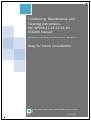
Functioning, Maintenance and
Cleaning instructions.
WF-WFM8-11-18-22-33-4055G400 manual
Manufactured on the basis of EN 62079:2002-01 – EN 60204-1
Keep for future consultation.
MA_B008_WF8-11-18-22-33-40-55G400_Chap 6-7_rev.00
1
30/03/2011
Index
6.
FUNCTIONING INSTRUCTIONS.................................................................................... 4
BIOLOGICAL RISK.................................................................................................................. 4
6.1
FUNCTIONING IN SAFE CONDITIONS........................................................................... 4
6.2
ROUTINE FUNCTIONING (MANUAL, AUTOMATIC FUNCTIONING)...................................... 5
6.2.1
DESCRIPTION OF THE APPLIANCE AND CONTROL PANEL................................................ 5
6.3
SELF-SERVICE........................................................................................................ 33
6.3.1
INSTALLATION OF THE EMERGENCY STOP BUTTON...................................................... 33
6.3.2
CARD SETTING....................................................................................................... 34
6.3.3
VERSIONS.............................................................................................................. 34
6.3.4
DISPLAY INDICATIONS............................................................................................ 34
6.3.5
CYCLE COST SETTING.............................................................................................. 35
6.4
OPENING AND CLOSING THE DOOR........................................................................... 36
6.4.1
LOADING THE SOAP IN THE DISPENSER DRAWER....................................................... 37
6.5
RECOMMENDATIONS FOR USING THE APPLIANCE........................................................ 39
6.5.1
SYMBOLS (LABEL) APPLIED TO THE FABRICS.............................................................. 40
6.6
WASHING CYCLE START-UP...................................................................................... 42
6.7
AUTOMATIC EXECUTION OF A PROGRAM.................................................................... 43
6.8
DESCRIPTIONS OF THE STANDARD PROGRAMS SUPPLIED WITH THE APPLIANCE............ 44
6.8.1
WEIGHING FUNCTION.............................................................................................. 47
6.9
CALIBRATION OF THE DWS SYSTEM.......................................................................... 47
6.10
SECONDARY FUNCTIONS......................................................................................... 48
6.10.1 INTRODUCTION TO THE PROGRAM............................................................................ 49
G400 CONTROL.................................................................................................................... 49
G400M CONTROL.................................................................................................................. 49
PROGRAMMING LIMIT FOR G400 AND G400M........................................................................... 50
6.11
SYMBOLS OF THE ICONS USED IN OPTIONS AND PROGRAMMING MODIFICATIONS......... 50
DISPLAY . ........................................................................................................................ 50
6.12
INSERT THE VARIOUS FLOW DIAGRAMS HERE............................................................ 50
APPLIANCE SWITCH-ON AND RELATIVE BASIC FUNCTIONS........................................................ 51
6.12.1 MODIFICATIONS AND DISPLAYS DURING THE PERFORMANCE OF A PROGRAM................ 51
6.12.2 APPLIANCE PARAMETERS MENU................................................................................ 52
6.12.3 SERVICE MENU....................................................................................................... 53
6.12.4 TEST CYCLE............................................................................................................ 53
6.12.5 CYCLES MENU (ONLY WITH G400M ELECTRONIC PROGRAMMER)................................... 53
6.12.6 PHASES MENU (ONLY WITH G400M ELECTRONIC PROGRAMMER).................................. 54
6.12.7 PRESET OPERATION................................................................................................ 56
6.13
FUNCTIONS/EXCEPTIONAL SITUATIONS..................................................................... 56
6.13.1 ABORT PROGRAM IN THE EVENT OF ANOMALIES......................................................... 56
6.13.2 DOOR RELEASE IN EMERGENCY................................................................................ 57
KG 8 G400, KG 11 G400, KG 18 G400 and KG 22 G400 DOOR RELEASE...................................... 57
KG 33 G400 , KG 40 G400 , KG 55 G400 DOOR RELEASE........................................................... 58
6.14
SIGNS TO OBSERVE................................................................................................ 58
6.15
INDIVIDUAL PROTECTION........................................................................................ 58
6.16
OPTIONAL MODULES, ADDITIONAL............................................................................ 58
6.16.1 QUICK REFERENCE INSTRUCTIONS........................................................................... 58
6.16.2 DISPOSAL OF WASTE............................................................................................... 59
USER INFORMATION............................................................................................................. 59
7.
MAINTENANCE AND CLEANING................................................................................. 60
7.1
SAFETY PRECAUTIONS............................................................................................. 60
7.2
SAFETY FUNCTIONS WITH WHICH THE APPLIANCE IS SUPPLIED................................... 61
7.3
MAINTENANCE AND CLEANING PERFORMED BY THE USER............................................ 62
7.3.1
CALIBRATION OF THE WEIGHING FUNCTION.............................................................. 62
7.3.2
DAILY AND WEEKLY CLEANING.................................................................................. 62
7.3.3
MONTHLY CLEANING................................................................................................ 62
7.3.4
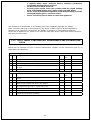
DAILY, WEEKLY AND MONTHLY MAINTENANCE AND CLEANING REGISTER....................... 63
7.4
ROUTINE MAINTENANCE AND CLEANING BY NOTIFIED OR TRAINED PERSONNEL............ 64
7.4.1
ROUTINE MAINTENANCE. MONTHLY CONTROL VALID FOR ALL MODELS.......................... 64
7.4.2
ROUTINE MAINTENANCE. MONTHLY LUBRICATION (KG 33 G400, KG 40 G400, KG 55 G400
ONLY).................................................................................................................... 65
2
7.4.3
7.4.4
7.4.5
ROUTINE MAINTENANCE. YEARLY CONTROL VALID FOR ALL MODELS............................. 66
ACCESS TO THE UNBALANCING MICRO SWITCH.......................................................... 66
ROUTINE MAINTENANCE. SPECIFIC ANNUAL CONTROL FOR KG 8 G400, WF11 G400, WF18
G400..................................................................................................................... 67
TENSIONING THE DRIVE BELTS.............................................................................................. 67
TIGHTNESS OF THE SCREWS................................................................................................. 68
7.4.6
ROUTINE MAINTENANCE. SPECIFIC ANNUAL CONTROL FOR KG 22 G400, KG M33 G400, KG 40
G400, KG 55 G400.................................................................................................. 68
TENSIONING THE DRIVE BELTS.............................................................................................. 68
TIGHTNESS OF THE SCREWS................................................................................................. 69
7.5
MODULE MAINTENANCE AND CLEANING BY QUALIFIED PERSONNEL.............................. 70
7.6
TROUBLESHOOTING. DIAGNOSIS AND REPAIRS, DISPLAY MESSAGES............................ 72
7.7
ALARMS DESCRIPTION............................................................................................ 72
7.7.1
ATTENTION MESSAGE DISPLAYED............................................................................. 78
TARE REQUEST MESSAGE...................................................................................................... 78
MAINTENANCE MESSAGE....................................................................................................... 78
“ENERGY SAVING SWITCH ME OFF” MESSAGE.......................................................................... 79
LUBRICATION REQUEST MESSAGE (KG 33 G400, KG 40 G400, KG 55 G400 ONLY)........................ 79
OPEN DISPENSER MESSAGE (ON KG 33 G400, KG 40 G400, KG 55 G400 ONLY)........................... 79
PAUSE MESSAGE.................................................................................................................. 79
DIFFERENT MESSAGES.......................................................................................................... 79
BLOCK APPLIANCE BETWEEN "XX" CYCLES MESSAGE................................................................ 79
POWER FAIL MESSAGE.......................................................................................................... 80
WIZARD MESSAGE............................................................................................ 80
Translation of the original instructions.
For any claims or observations the reference text is the original one in the manufacturer's language i.e.
Italian.
3
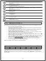
6.FUNCTIONING INSTRUCTIONS
Attention!
• Any person using this appliance must read this user manual.
• The appliance must only be used by trained persons.
• The appliance cannot be used by persons (including children) with
reduced physical, sensorial, mental capacities or with little experience
or knowledge unless they have been examined or trained regarding
the use of the appliance by suitably trained staff that is responsible for
his/their safety.
• The appliance has not been designed to be used in environments
subject to the ATEX Standard, relative to explosive atmospheres.
• The appliance cannot handle laundry that has been in contact or soaked
in inflammable substances.
• Before performing and cleaning or maintenance, make sure that the
hot water, cold water and steam cocks are closed (in the appliances
with the type of heating) and the master switch is off.
• Keep inflammable liquids away from the appliance.
• Keep cleaning and soap products away from the appliance and locked
in a cabinet.
• Children must be controlled so that they do not play with the appliance.
BIOLOGICAL RISK
Attention!
• The kg8, kg11, kg18 and kg22 appliances are fitted with a WRASapproved mechanical device (air gap), which prevents the undesired
return of water loaded into the appliance back into the water network.
• The kg33, kg40 and kg55 appliances are fitted with a mechanical
device (air gap), which prevents the undesired return of water loaded
into the appliance back into the water network.
• The appliance has not been designed to disinfect linen.
6.1
FUNCTIONING IN SAFE CONDITIONS
Attention!
• The operator must be able to control the dispenser drawer comfortably;
if he is not tall enough, build a suitable platform
• Never open the dispenser when the appliance is running.
• Carry out all soap loading operations when the appliance is not running.
A condition that ensures the appliance is not running is with the door
open.
• Any injury/damage to persons, animals, objects or environment cause
by the non-application of this warning, cannot be blamed on the
manufacturer.
• In the event of appliance malfunctioning, remove the power supply via
the isolating switch.
4
Check that the laundry trolleys are lower than the lower limit of the door. Do not allow the
trolleys to strike thedoor, thus causing damage.
The KG 33 G400, KG 40 G400 and KG 55 G400 models are equipped with a sensor that puts the
appliance in pause if the dispenser is opened. Close the dispenser and press the start button to
re-start the washing program.
6.2
ROUTINE FUNCTIONING (MANUAL, AUTOMATIC FUNCTIONING)
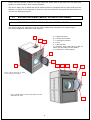
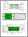
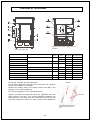
6.2.1 DESCRIPTION OF THE APPLIANCE AND CONTROL PANEL
The figures show the appliances with the main components necessary for functioning as
well as the appliance electronic control panel.
A = dispenser door.
B = smart card reader.
C = emergency button.
D = door.
E = door handle.
F = dispens door hook (only on KG 33
G400, KG 40 G400, KG 55 G400).
G = electronic control panel.
A
C
B
D
E
G
A
F
G
C
B
E
Figure 1 KG 8 G400, KG 11 G400,
KG 18 G400, KG 22 G400
Figure 2 WFM 33KG 33 G400, WFM 40KG 40 G400,
WFM 55KG 55 G400
D
5
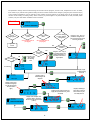
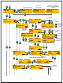
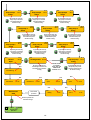
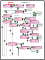
Possibility for preset (see instructions point
Z page 26 ), programming with PC or smart
card (see specific instructions)
Program
number
P 01 90°C
Start message with
FW-software version and
appliance version display
Switch-on
Insert technicians name using the
SEL, + and – and Enter keys
Total duration of
the program
00:30
Program name
Door status
0/1000
Cycles reset confirmation appears for a few seconds
MAINTENANCE
Change
ECO function
Change
cycle
Technician:
Cycles
Select day
month and
year using +
and – keys and
confirm with
enter
MAINTENANCE
MAINTENANCE
XXXX/1000
Date
Machine
ready
Selection
ECO
MAINTENANCE
Cycles
Washing temperature
dd/mm/yy
Hold
down for
8”
YES
See instructions point F
(see page 27 )
Door closed?
Programming
NO
TRACK DATA
Consultation
menu
only for
technical
assistance see
point L (see
page 12 )
10 times
in 15”
P 01 90°C
Programming
00:30
SERVICE
PHASES XX XX XX XX XX XX XX
Door status
Cycle phases
sequence display
See instructions point B
(see page 9 )
MACHINE PAR. FOR
CALIBRATIONS
Programming
Close the door
MACHINE PAR. FOR
Door block
procedure
(10” )
G 400
See instructions point M
(see page 21 )
Close the door
Programming
Door blocked?
YES
PHASES
MACHINE PAR. FOR
NO
CALIBRATIONS
Error
E6, door
anomaly
Door closed
See instructions point N
(see page 18 )
Programming
Program
execution
G 400 M
P 01
Phase nrXX
Phase name
CYCLES
MACHINE PAR. FOR
Tare cycle
execution
CALIBRATIONS
PHASE IN PROGRESS
6
P 01 90°C
Program name
Door status
00:30
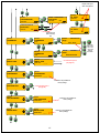
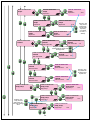
See instructions point A
(see page 6 )
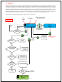
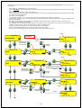
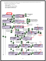
When start is pressed, the door lock procedure begins and, if successful, the cycle starts. The stop/start key can be
pressed during execution of the program. At every press the cycle will pass to the end of the phase in progress or to the
next phase, depending on the same. By holding thestart key down for 5”, the machine will abort the cycle, will check
the safety conditions and therefore release the door. Attention, the cycle duration time is in self-learning mode, i.e. every
machine cycle will measure the real time from pressing the start key to the end of the cycle and will re-propose the time
measured and updated for every cycle. If the cycle is by-passed or shortened via the start key, this time is falsified but
the washing machine will perform the phases in the correct sequence even if the time displayed is 00:00.
All functions are stopped during the pause and the water is not drained.
Phase number
and code
Program
number
Point A
P 01
Change
cycle
YES
NO
Phase nrXX
Phase name
If pressed together
(option not valid on
pin phases)
Have 2’
passed from
cycle start?
Held
down for
10”
YES
Ignore the
control
NO
YES
Is it a Soak Prewash
Wash Rinse or
unrolling phase ?
Go to the end
of the phase
in progress
NO
YES
Is it the spin
phase ?
Carry out slow
down and pass to
the next phase
NO
Is it the last
phase of the
program ?
YES
Check water level
and drum speed and
then release the door
NO
Pass to the next
phase
PAUSE
00:00:00
PHASE IN PROGRESS
Do not change
anything
Is it the weighing phase ?
Display of phase in progress
and time to cycle end
Door released ?
NO
Error E6,
door anomaly
YES
P 01 90°C
00:30
Program name
Open door
7
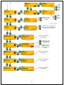
Phase data
consultation
in progress
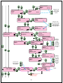
See instructions point C
(see page 7 )
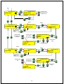
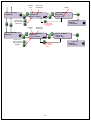
It is possible to change some functions during the execution of the program, such as: level, temperature or time. In detail,
if the mode key is pressed during water loading the level of water loaded can be changed (using the plus and minus keys)
or the heating temperature can be changed (if the machine is being heated) or the phase time can be changed (if the
machine is not heating or loading water). If the mode key is pressed again or in phases different to Soak, Prewash, Wash
or Rinse, only the information available can be consulted.
Point C
P 01
Phase nrXX
Phase name
PHASE IN PROGRESS
Is it the
weighing phase
Is it the soaking,
pre-wash, washing,
rinsing phase
Is it the unroll
phase
Is it the spin
phase
See instructions point D
(see page 8 )
See instructions point D
(see page 8 )
Ignore the
control
NO
YES
Is the water
heating ?
NO
YES
Using the + and
– keys, change
the washing
time
Is it washing ?
P 01
NO
P 01
It is draining
Is water being
loaded?
Using the + and – keys, it
is possible to change the
heating temperature of
the water in the tub during this phase
YES
P 01
Phase nrXX
Phase name
-°C xx°C
0 cm
xx cm
Phase nrXX
Phase name
-°C xx°C
Phase nrXX
Phase name
xx sec Using the + and – keys, it is
possible to change the “target” level of the water in the
tub during this phase
0 cm
xx cm
0 cm
xx cm
Display of type
of water loading
in the tub
P 01
Phase nrXX
Phase name
Display of type of
water loading in the
dispenser
Drain open
Display of soap pump
activation time (pump
1 in the top left pump
10 in the bottom
right)
P 01
xx
xx
P 01
Phase nrXX
Phase name
PHASE IN PROGRESS
P 01
Hot water lit
xx
P 01
Phase nrXX
Phase name
Disp.
A
xx
Phase nrXX
Phase name
xx
xx
xx
xx
xx
xx
B
xx
Display of the dissipator temperature ( FRU-1 ) and of the
electronic circuit of the inverter
( FRU-2 )
P 01
rpm.
xx/xx
FRU-1
xx °C
Display of enabling of
drain valves 1 and 2 at
drain end and any closure delay time set.
Phase nrXX
Phase name
Left Pause Right
xx
xx xx
P 01
Phase nrXX
Phase name
Phase nrXX
Phase name
Enab. after
Phase end
FRU-2
xx °C
8
Hard Soft
xx xx
C
xx
Display of drum speed (current and
target) hourly activation time, pause
and anti-El
xx
off
P 01
Phase nrXX
Phase name
xxSec xxSec
xx xx
Point D
P 01
Phase nrXX
Phase name
PHASE IN PROGRESS
Is it the unroll
phase
Is it the spin
phase
Display of drum speed (current and
target) hourly activation time, pause
and anti-El
P 01
P 01
Phase nrXX
Phase name
Load balancing
xxSec
xx/xx rpm.
rpm.
xx/xx
Left Pause Right
xx
xx xx
P 01
P 01
Phase nrXX
Phase name
Phase nrXX
Phase name
During distribution 1, the time of the
function in progress and the drum
speed are displayed.
Distribution 1
xxSec
xx/xx rpm.
Washing Normal
xxSec
xx/xx rpm.
P 01
Display of the drum
speed (current and
target) and phase duration time
P 01
During distribution launch, the time
of the function in progress and the
drum speed are displayed.
Phase nrXX
Phase name
Phase nrXX
Phase name
Distribution 2
xxSec
xx/xx rpm.
X
During distribution 2, the time of the
function in progress, the drum speed
and the type of electronic unbalance
are displayed (a = very unbalanced →
c = slightly unbalanced)
Phase nrXX
Phase name
PHASE IN PROGRESS
P 01
Phase nrXX
Phase name
Spin X
xxSec
P 01
xx/xx rpm.
Phase nrXX
Phase name
Slowing
xxSec
9
xx/xx rpm.
During spinning (1, 2 or 3), the time
of the function in progress and the
drum speed are displayed.
During slow down, the maximum
time of the function in progress and
the drum speed are displayed.
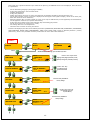
With the door open by pressing the mode key, enter options programming (MACHINE PARAMETERS ). From this menu it
is possible to:
- hide cooling (if envisioned in the cycle sequence)
- change the time (not speed) of the final spin (the value is expressed as a percentage of the nominal time of the final
spin)
- hide prewash (if envisioned in the cycle sequence)
- carry out delayed start-up (enable the function and time desired on exiting programming, on pressing the start key
the delay countdown will begin)
- the buzzer can be disabled
- it is possible to remove 10 °C of heating (on all cycles and phases) by selecting “reduced”.
- cycles can be enabled (in the event of disabling they will be hidden not deleted) that therefore will not be displayed by
pressing the SEL key
- the drum can be stopped during loading and draining of water (particularly indicated in wool or delicate cycles)
- the heating hysteresis can be changed
- the activation level of the liquid soap pumps can be changed (only if connected). The minimum level depends on the
washing machine version. The level must never exceed the washing level.
- draining can be "forced"(option not recommended) after every loading
- dummy cycle temperatures can be set instead of the real ones (or set)
- fixed cycle execution display times can be set (instead of in self-learning or real)
flashes
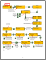
Point B
Programming
MACHINE PAR. FOR
MACHINE PAR.
COOL
Escape without
saving
Selecting cycles
from 1 to 20 using + and - keys
CYCLE 01 NO
Save and
escape
MACHINE PAR. FOR
MACHINE PAR. FOR
COOL
MACHINE PAR. FOR
COOL
COOL
CYCLE 01 YES
CYCLE 01 YES
flashes
flashes
MACHINE PAR. FOR
MACHINE PAR. FOR
MACHINE PAR. FOR
SPIN
SPIN
SPIN
CYCLE 01 YES
CYCLE 01 100%
Flashing can be set between “no spin” =
0% and 150% of the nominal timeof the
final spin
Selecting cycles
from 1 to 20 using + and - keys
Escape without saving
Save and
escape
MACHINE PAR. FOR
SPIN
MACHINE PAR. FOR
MACHINE PAR. FOR
MACHINE PAR. FOR
PRE-WASH
PRE-WASH
PRE-WASH
Selecting cycles
from 1 to 20 using
+ and - keys
CYCLE 01 XXX%
CYCLE 01 YES
CYCLE 01 YES
flashes
Save and
escape
Escape without saving
Flashes
MACHINE PAR. FOR
PRE-WASH
10
CYCLE 01 NO
MACHINE PAR. FOR
MACHINE PAR. FOR
MACHINE PAR. FOR
START DELAY
START DELAY
START DELAY
disabled
disabled
Using the + and –
keys, set the time for Flashes
delayed start-up
Flashes
On escaping the machine parameters
programming and the start button is
pressed, “DELAYED START-UP XXh ; xx
min will appear
MACHINE PAR. FOR
MACHINE PAR. FOR
START DELAY
START DELAY
Flashes
START DELAY 00h : 00min
Flashes
enabled
MACHINE PAR. FOR
MACHINE PAR. FOR
MACHINE PAR. FOR
BUZZER
BUZZER
BUZZER
enabled
Save and
escape
disabled
Flashes
Flashes
MACHINE PAR. FOR
MACHINE PAR. FOR
MACHINE PAR. FOR
HEATING
HEATING
HEATING
normal
reduced
Save and
escape
MACHINE PAR. FOR
MACHINE PAR. FOR
ENABLING
ENABLING
CYCLE 01
Selecting cycles
from 1 to 20 using + and - keys
MACHINE PAR. FOR
ENABLING
enabled
CYCLE 01
flashes
Save and
escape
Escape without saving
Flashes
MACHINE PAR. FOR
ENABLING
CYCLE 01
MACHINE PAR. FOR
MACHINE PAR. FOR
CYCLE 01
Selecting cycles
from 1 to 20 using
+ and - keys
disabled
MACHINE PAR. FOR
C/S DRUM MOV.
C/S DRUM MOV.
enabled
C/S DRUM MOV.
yes
CYCLE 01
yes
Flashes
Escape without saving
Save and
escape
Flashes
MACHINE PAR. FOR
MACHINE PAR. FOR
MACHINE PAR. FOR
C/S DRUM MOV.
CYCLE 01
HYSTERESIS
HEAT, HYSTERESIS
Hysteresis
5°C
Use the + and – keys,
set the heating
hysteresis value
Escape without saving
Save and escape
11
no
MACHINE PAR. FOR
MACHINE PAR. FOR
PUMPS LEVEL
PUMPS LEVEL
Pumps start
4 cm
Using the + and –
keys, set the time for
delayed start-up
Escape without saving
Save and escape
Flashes
MACHINE PAR. FOR
Flashes
MACHINE PAR. FOR
R. TEMPERATURE
MACHINE PAR. FOR
R. TEMPERATURE
R. TEMPERATURE
SET
DUMMY
Save and escape
Escape without
saving
Selecting display
temperature from
1 to 100°C
Selecting cycles
from 1 to 20 using + and - keys
R. TEMPERATURE MACHINE PAR.
DUMMY
CYCLE 01
°C
Escape without
saving
R. TEMPERATURE MACHINE PAR.
DUMMY
CYCLE 01
Save and escape
XX°C
Flashes
Flashes
MACHINE PAR. FOR
MACHINE PAR. FOR
CYCLE TIME
MACHINE PAR. FOR
CYCLE TIME
CYCLE TIME
REAL
ARBITRARY
Save and escape
Escape without
saving
Selecting display
time
Selecting cycles
from 1 to 20 using + and - keys
MACHINE PAR. FOR
DUMMY
CYCLE 01
00:30
Escape without
saving
MACHINE PAR. FOR
DUMMY
CYCLE 01
Save and escape
XX:XX
12
If the mode key is pressed with door open and then the plus key, the SERVICE menu can be displayed. From this menu
it is possible to:
-
-
-
-
-
-
-
-
-
-
-
-
set the functioning language (8 languages available)
change the temperature unit of measurement
lengthen draining time
change the password
display the machine log such as, water and electricity consumption divided by the total and last cycle
set the start message (“large” comment is displayed in the top part of the ignition display, “small” in the lower part,
both with maximum of 16 characters)
block the machine after a certain number of cycles. It can only be unblocked by a code supplied by the manufacturer.
test all appliance functions /see specific instructions).
change the times relative to the water draining (E2) and heating (E4) alarms
set the level given to the economy key ( ECO )
set heating with lower real temperature
Check the last 10 alarms occurring and stored
In order to be displayed, the other menu address parameters (SPIN MOTOR, MACHINE TYPE, PASSWORD 2, CONVERSION,
COIN OPERATED, WATER LOAD, MAINTENANCE, TARE CYCLE, DOOR TYPE) require a different password ( factory
password 2), which is only available to factory technicians ad not for after-sales assistance.
Point L
Programming
SERVICE
SERVICE
SERVICE
INSERT
PASSWORD
-----6 times
SERVICE
LANGUAGE
SERVICE
TYPE OF DEGREES
------
“ENTER PASSWORD” message, press the ECO key 6 times
SERVICE
Use the + and – keys to set the
language from (English, German, French,
Spanish, Portuguese, Rumanian, Russian)
LANGUAGE
Italian
SERVICE
TYPE OF DEGREES
Celsius
SERVICE
SERVICE
SPIN MOT.
SPIN MOT.
Password 2 only available for
factory settings.
Password 2 ------
SERVICE
SERVICE
DRAIN TIME
DRAIN TIME
SERVICE
MACHINE TYPE
Drain time:
Use the + and – keys
to set degrees Centigrade or Fahrenheit
30 sec
Use the + and – keys to set
new draining time ( min
15, max 180 sec.)
Password 2 only available for
factory settings.
SERVICE
MACHINE TYPE
Password 2 ------
13
Press the ECO key 6 times
SERVICE
PASSWORD
Password 2 only available for
factory settings , NOT AVAILABLE
for assistance
Press the new sequence of 6 keys
SERVICE
SERVICE
SERVICE
PASSWORD
PASSWORD
PASSWORD
New password 1: - - - - - - -
Old password 2: - - - - - - -
Old password 1: - - - - - - -
SERVICE
SERVICE
CONSUMPTION
Power
Save and
escape
CONSUMPTION
Escape without
saving
Resistances Kw
SERVICE
SERVICE
CONSUMPTION
Use the +
and – keys
to set
power
CONSUMPTION
Power
Power
Resistances Kw
Display of last
cycle heating
consumption
SERVICE
X.X Kw
Save and
escape
CONSUMPTION
POWER
Escape without
saving
Motor Kw.
SERVICE
CONSUMPTION
SERVICE
POWER
Cycle last heat.:
Use the +
and – keys
to set
power
CONSUMPTION
Power
X.XX Kw/h
Motor Kw.X.X Kw
SERVICE
CONSUMPTION
SERVICE
CONSUMPTION
POWER
POWER
Last cyc. rinse:
Cycle last mot.:
SERVICE
X.XX Kw/h
Display of last
cycle heating
consumption
CONSUMPTION
POWER
Last cyc. mot.:
SERVICE
SERVICE
CONSUMPTION
CONSUMPTION
SERVICE
TOTAL
TOTAL
Total
CONSUMPTION
Hours worked: Total heating:
X:XX
X:XXKw/h
Display of hours worked, (total) electric heating and
motor consumption and cycles carried out.
SERVICE SERVICE CONSUMPTION
TOTAL
TOTAL
Total Cycles:
SERVICE
CONSUMPTION
Lit. water
CONSUMPTION
Total Motor:
X
SERVICE Lit. water
Soft
14
cold:
CONSUMPTION
X
lit
X:XX Kw/h
Display of last
cycle water
consumption
Display of last cycle
water consumption
SERVICE
SERVICE
Hard cold:
Total water
CONSUMPTION
Total cold:
Total water
CONSUMPTION
Lit. water
SERVICE CONSUMPTION
X lit
X lit
CONSUMTION SERVICE
Total water
Total hot:
SERVICE
X lit
Hot:
Display of total
water consumption
SERVICE
SERVICE
SERVICE
COMMENTS
COMMENTS
Large
Large
SERVICE
SERVICE
MACH. LOCK
MACH. LOCK
See instructions point P
(see page 28 )
______
SERVICE
SERVICE
CONVERSION
CONVERSION
COMMENTS
WASHING MACHINE
Small
Block code
G400 – WF XX
Small
COMMENTS
PASSWORD 2 ______
Password 2 only available for
factory settings.
SERVICE
See instructions point T
(see page 16 )
SERVICE
SERVICE
COIN OPERATED
COIN OPERATED
Password 2 only available for
factory settings.
PASSWORD 2 ______
SERVICE
SERVICE
WATER LOAD
WATER LOAD
Password 2 only available for
factory settings.
PASSWORD 2 ______
15
X lit
CONSUMPTION
SERVICE
SERVICE
MACHINE TEST
CONSUMPTION
Lit. water
Select the
letter using
the + and
– keys and
confirm
with enter
SERVICE
SERVICE
TIME-OUT
TIME-OUT
Heating
Heating:
SERVICE
SERVICE
SERVICE
TIME-OUT
TIME-OUT
TIME-OUT
Water load
SERVICE
SERVICE
ECONOMY
ECONOMY
Heating:
xxxx sec
Use the
+ and –
keys to
set value
Use the + and – keys,
to set the value (min
5, max 30)
Economisation:
Use the
+ and –
keys, to
set the
value
(min 1,
max 5)
X°C/20min
XX%
Wording in English!
SERVICE
SERVICE
HEATING
HEATING
Heating:
SERVICE
SERVICE
MAINTENANCE
MAINTENANCE
XXXX
Password 2 only available for
factory settings.
PASSWORD 2 ______
Using the + and – keys
it is possible to scroll
the last 10 alarms
Log not stored
SERVICE
LOG AL. SERVICEXX
AL. LOG
XX xxxxxxxxxx
Description of the alarm
Details of the alarm
(cycle in progress and
phase)
CYCLE XX Phase XX
SERVICE
SERVICE
TARA CYCLE
TARA CYCLE
SERVICE
SERVICE
DOOR TYPE
DOOR TYPE
SERVICE
SERVICE
LUBRICATION
LUBRICATION
Using the + and – keys, set the value
(High = normal, Low = the temperature
at 90°C in realty it is 8°C lower)
Password 2 only available for
factory settings.
PASSWORD 2 ______
Password 2 only available for
factory settings.
PASSWORD 2 ______
Password 2 only available for
factory settings.
PASSWORD 2 ______
16
Point T
SERVICE
SERVICE
MACHINE TEST
MACHINE TEST
MODEL
PASS
WFY XX G4
Confirm the result of the
last machine test performed (PASS or NO PASS)
SERIAL NUMBER
XXXXXXXXXX
Select the letter using the +
and – keys and
confirm with
enter
D950= XXX
D951= XXX
D952= XXX
D953= XXX
Inverter data reading
(firmware, parameters, size)
Status of the door micro
switch, lock and unbalancing
Check that the
drain is closed
TEST
Dispenser A
Active
XX °C
XX cm
By pressing the enter key,
the load on dispenser A is
activated and deactivated
(to be checked visually)
TEST
Soft in tub Active
Close the door
Door closed
Drain closed
TEST
Dispenser B
Active
By pressing the enter
key, the loading of soft
cold water into the tub
is activated and deactivated (to be checked
visually)
XX °C
XX cm
By pressing the enter key,
the load on dispenser B is
activated and deactivated
(to be checked visually)
TEST
XX °C
XX cm
Hard in tub Active
BEFORE PASSING TO THE
NEXT PHASE,
WAIT FOR 6
cm. OF WATER
IN TUB
- door
- unbal- closed
TEST
TEST
TEST
Block micro switch
micro switch open
ancing M. open D954= XXX
D955= XXX
D956= XXX
D957= XXX
TEST
XX °C
XX cm
Dispenser C
Active
The load is activated or deactivated by pressing the enter key
on dispenser C (to be
checked visually)
XX °C
XX cm
By pressing the enter key, the
loading of hard cold water
into the tub is activated and
deactivated (to be checked
visually)
17
Close the door
TEST
Hot in tub Active
XX °C
XX cm
By pressing the enter key, the
loading of hot water into the
tub is activated and deactivated
(to be checked visually)
TEST
TEST
XX °C
XX cm
Soap pump 1
Active
Soap pump 2
Active
By pressing the enter key,
soap pump 1 is activated
and deactivated (to be
checked visually)
Soap pump 6
Active
Soap pump 5
Active
By pressing the enter key,
soap pump 6 is activated
and deactivated (to be
checked visually)
Soap pump 7
Active
Soap pump 8
Active
By pressing the enter key,
soap pump 7 is activated
and deactivated (to be
checked visually)
TEST
XX °C
XX cm
Unload
Open
Wait
Wait
TEST
Load balancing
xx sec.
TEST
Heating Active
TEST
XX °C
XX cm
Injector pump
Active
BEFORE PASSING
TO THE NEXT
PHASE, WAIT FOR
TEMPERATURE
INCREASE OF 5°C
TEST
Spin 1
Door release
procedure
TEST
Heating
Positive inspection confirmation message
P 01 90°C
00:30
Program name
Open door
18
XX °C
XX cm
By pressing the enter key,
the injector pump is activated and deactivated (to
be checked visually)
Wait
Wait
TEST
Spin 2
xx sec.
Wait
Machine test
PASS
XX °C
XX cm
By pressing the enter key,
soap pump 9 is activated
and deactivated (to be
checked visually)
Wait
xx sec.
XX °C
XX cm
By pressing the enter key,
soap pump 4 is activated
and deactivated (to be
checked visually)
Soap pump 9
Active
By pressing the enter key,
the heating is activated and
deactivated (to be checked
visually)
TEST
Distribution 2
Soap pump 4
Active
TEST
XX °C
XX cm
By pressing the enter key,
soap pump 8 is activated
and deactivated (to be
checked visually)
Wait
TEST
Distribution 1
TEST
XX °C
XX cm
By pressing the enter key,
soap pump 5 is activated
and deactivated (to be
checked visually)
TEST
XX °C
XX cm
By pressing the enter key,
soap pump 3 is activated
and deactivated (to be
checked visually)
TEST
XX °C
XX cm
XX °C
XX cm
Soap pump 3
Active
By pressing the enter key,
soap pump 2 is activated
and deactivated (to be
checked visually)
TEST
TEST
TEST
XX °C
XX cm
xx sec.
Wait
xx sec.
TEST
Spin 3
xx sec.
The sequences of the phases in the washing cycles can be changed with G400 M, using the mode key with door open.
In particular, from the CYCLES menu it is possible:
-
-
-
-
-
-
Replace one phase with another
Delete a phase
Insert a phase after a phase selected
Insert a phase before a phase selected
Copy a cycle onto a different cycle
Copy a different cycle onto a cycle
Point N
Use the + and – keys
to select the desired
program
Programming
Programming
CYCLE XX
CYCLES
XXXXXXXXXXXX
Cycle XX XXXXXXXXX
Program name
Select the letter using the +
and – keys, to confirm the
new program name with max
15 characters using enter
Cycle XX XXXXXXXXX
Comment
COMMENT
XXXXXXXXX
Selected
phase
Cycle XX XXXXXXXXX
Phase number in
the library
Category of the
phase selected
Abbreviated name of
the phase selected
flashing
Cycle XX XXXXXXXXX
XXXXXXX
01 Phase
XX XXXXXXX
Phases
Cycle XX XXXXXXXXX
XX Phase
Modification
XX
Phase XX COPY?
Save and
escape
Use the + and –
keys to select the
desired phase
Use the + and –
keys to select the
desired phase
Cycle XX XXXXXXXXX
XXXXXXX
XX Phase
XX XXXXXXX
Modification
Cycle XX XXXXXXXXX
XX Phase
Modification
XX
Phase 01 SPIN
Escape deleting the phase
from the program
Cycle XX XXXXXXXXX
XXXXXXX
XX Phase
XX XXXXXXX
Cancel
Cycle XX XXXXXXXXX
XX XXXXXXX
XX Phase
DELETE?
Save and
escape
Use the + and –
keys to select the
desired phase
Escape without
saving
Cycle XX XXXXXXXXX
Before ins.
XX Phase
XX
Phase 01 SPIN
Cycle XX XXXXXXXXX
XXXXXXX
XX Phase
XX XXXXXXX
Before ins.
flashing
Cycle XX XXXXXXXXX
Phase
XX XX Before ins.
Phase XX Before Ins.?
Save and
escape
Use the + and –
keys to select the
desired phase
Cycle XX XXXXXXXXX
XXXXXXX
XX Phase
XX XXXXXXX
After ins.
flashing
Escape without
saving as with less
button
Escape without
saving
Cycle XX XXXXXXXXX
After ins.
XX Phase
XX
Phase 01 SPIN
19
flashing
Cycle XX XXXXXXXXX
Phase
XX XX After ins.
Phase XX After Ins.?
Selected
cycle
Cycle XX XXXXXXXXX
Copy from
Name of the
selected cycle
Copy from
Copy from
CYCLE XX XXXXXXX
CYCLE XX COPY?
Programming
Selected
cycle
Copy into
Use the + and –
keys to select the
cycle to copy that
displayed
Cycle XX XXXXXXXXX
Cycle XX XXXXXXXXX
Use the + and –
keys to select the
cycle to copy
Cycle XX XXXXXXXXX
flashing
Name of the
selected cycle
CYCLE XX
Escape without
saving as with less
button
XXXXXXXXXXXX
Cycle XX XXXXXXXXX
Cycle XX XXXXXXXXX
Copy into
Copy into
CYCLE XX XXXXXXX
CYCLE XX COPY?
Programming
Escape without
saving as with less
button
20
CYCLE XX
XXXXXXXXXXXX
With G400 M, by pressing the mode key with door open and then the plus key, the details of the individual phases can
be changed (level, temperature, duration, drum movement, etc.). In detail, in the PHASES menu it is possible:
-
-
-
-
-
-
Disable a phase (it is deleted). If this phase has been inserted in a program, the same will be by-passed.
Change the destination between soak, prewash, wash, rinse, spin or unrolling
In the soak, prewash, washing, rinse phases, it is possible to set:
an abbreviation of the phase name
to set the type of drum movement (rotation time, pause and speed)
heating temperature and temperature maintenance time
cooling and water level to maintain during this function (attention not to set a cooling temperature
higher than the heating temperature or a cooling temperature lower than the inlet cold water temperature.
Level 1 must be equal to the previous washing level.
The water level in the tub during these phases and the time to maintain this level if there is no heating
function. If the load level is set after 99 cm, “overflow” appears and in this phase the machine loads water for
the maintenance time in continuation. The minimum water level depends on the version of the machine
(in the event of level lower than the resistances, heating does not take place).
The water load the tub with several water valves (hot suggested on cycles with high heating
temperature,hard cold suggested on rinses or soft cold suggested on low temperature heating cycles)
Loading the small soap tanks (soap drawer) A (powder for prewash), B (powder for wash) or C (liquid
for softener at last rinse). The load in the small tanks starts to reach the load level set.
enable draining at phase end, particularly useful if final spin must be performed, which if carried out
with distribution with water in tub, has better load balance or if successive phases must be performed without
draining the water.
The liquid soap loading time (on machines with pumps card option and pumps) where it is possible
to activate the pumps for a determined period of time. The pumps from 1 to 9 are activated for the time set
on reaching the pumps level set in the“MACHINE PARAMETERS” menu. However, if the injector pump is set
differently to 0 seconds, it is powered for the entire phase when the water in the tub is at a level higher than
the safety level.
The following can be set in the spin phases:
the distribution time 1 (set minimum 10 sec. if distribution 2 is also used).
the distribution time 2 (set minimum 10 sec. if spin 1 is also used).
the distribution time 1 (set minimum 70 sec. if distribution 2 is also used).
the spin time 2 (set minimum 40 sec. if spin 3 is also used).
spin 3 time (do not set times longer than 180 sec. Longer times have no real impact on the result)
the maximum number of re-starts if unbalancing is detected
whether to perform start-up with water in tub; particularly useful for better balancing before final
spinning
(the previous phase must have the phase end draining disabled! ).
The following can be set in the unrolling phases:
the phase time
the type of drum movement (rotation time, pause and speed)
A phase can be copied instead of a different one using the COPY IN or COPY FROM controls.
Attention, on completion of all phase modifications, confirmation is requested for storage of these modifications. They
will be stored if the enter key is pressed. If the plus or minus key is pressed programming will be exited without saving!
Phase 45 is dedicated to the weighing function that cannot be performed in the kg 33, kg 40 and kg 55 washing
machine models and can be inserted only as first phase.
21
“ENTER PASSWORD” message, press
the ECO key 6 times
Point M
Programming
PHASES
PHASES
PHASES
INSERT
PASSWORD
------
-----Selected
phase
6 times
Use the + and – keys
to select the cycle into
which to copy that
displayed
Programming
PHASE 01
SPIN
Select the letter using
the + and – keys,
to confirm the new
program name with
max 15 characters
using enter
CEN1000RPM
Category of the phase selected
Abbreviated name of the phase selected
PHASE XX XXXXXXXXX
DISABLED
The phase is deleted
PHASE XX DISABLED
Comment
Comment
XXXXXXXXXXX
PHASE XX XXXXXXXXX
PHASE XX XXXXXXXX SOAK
SOAKING
Motor
Normal washing: YES
PHASE XX XXXXXXXX SOAK
PHASE XX XXXXXXXX SOAK
Motor
Motor
Using the + and
– keys, activate
washing and the
drum speed (min
23 max 57 rpm)
Normal washing
PHASE XXXXXXXXXX SOAK
Motor
Normal washing:
0rpm
PHASE XX XXXXXXXX SOAK
Motor
Right/Left rotation
PHASE XXXXXXXXXX SOAK
Motor
Right/Left rotation:
0.0 sec
SOAK XX XXXXXX PHASE
Motor
Pause
PHASE XX XXXXXXXX SOAK
Motor
Pause:
Using the
+ and –
keys, insert
the drum
rotation time
(min 3 sec.)
and pause
time
0.0 sec
PHASE XX XXXXXXXX SOAK
Heat
PHASE XX XXXXXXXX SOAK
PHASE XX XXXXXXXX SOAK
Heat
Heat
Temperature
Temperature:
Using the + and – keys,
select the washing
temperature (min 20,
max 90°C )
22
--°C
PHASE XX XXXXXX SOAK
PHASE XX XXXXXX SOAK
Heat
Heat
Maintenance Maintenance
: 0 sec
PHASE XX XXXXXX SOAK
PHASE XX XXXXXX SOAK
Heat
Heat
Drum movement
Drum movement
Using the + and
– keys, insert
the maintenance
time and, if necessary, activate
drum movement
during heating.
: no
Using the + and – keys, select the washing end
temperature (min 20, max 90°C)
PHASE XX XXXXXX SOAK
PHASE XX XXXXXX SOAK
PHASE XX XXXXXX SOAK
Cool
Cool
Cool
Temperature
Temperature
: --
PHASE XX XXXXXX SOAK
PHASE XX XXXXXX SOAK
Cool
Cool
1st Level
1st Level
: --
Water is drained and loaded during cooling, via
the + and – keys insert the levels within which this
routine must be performed.
PHASE XX XXXXXX SOAK
PHASE XX XXXXXX SOAK
Cool
Cool
2nd Level
2nd Level
: --
PHASE XX XXXXXX SOAK
PHASE XX XXXXXX SOAK
PHASE XX XXXXXX SOAK
Level
Water level
Level
Set water level
: 0 cm
using the + and – keys, insert the washing water level and the maintenance
time (if phase without heating)
PHASE XX XXXXXX SOAK
PHASE XX XXXXXX SOAK
Level
Level
Maintenance
Maintenance
PHASE XX XXXXXX SOAK
PHASE XX XXXXXX SOAK
PHASE XX XXXXXX SOAK
Load
Load
Load
Hot in tub
Hot in tub
Load
Load
Hard in tub
Hard in tub
PHASE XX XXXXXX SOAK
PHASE XX XXXXXX SOAK
Load
Load
Soft in tub
23
: XX
PHASE XX XXXXXX SOAK
PHASE XX XXXXXX SOAK
Soft in tub
: 0 sec
: XX
: XX
Using the + and
– keys, enable
water loading of
water into the
tub
PHASE XX XXXXXX SOAK
PHASE XX XXXXXX SOAK
PHASE XX XXXXXX SOAK
Soaps
Soaps
Soaps
Dispenser A
Dispenser A
PHASE XX XXXXXX SOAK
PHASE XX XXXXXX SOAK
Soaps
Soaps
Dispenser B
Dispenser B
: 0 sec
Using the + and
– keys, set the
loading times
into the small
soap tanks (
A = prewash,
B = wash, C =
softener)
: 0 sec
PHASE XX XXXXXX SOAK
PHASE XX XXXXXX SOAK
Soaps
Soaps
Dispenser C
Dispenser C
: 0 sec
PHASE XX XXXXXX SOAK
PHASE XX XXXXXX SOAK
PHASE XX XXXXXX SOAK
Unload
Unload
Unload
Enab. drain 1 after
Enab. drain 1 after
: XX
Using the + and – keys, insert
the delay time for closure of the
discharge valves
PHASE XX XXXXXX SOAK
PHASE XX XXXXXX SOAK
Unload
Unload
Enab. drain 2 after
Enab. drain 2 after
PHASE XX XXXXXX SOAK
PHASE XX XXXXXX SOAK
Unload
Unload
Phase end drain 1
Phase end drain 1
: XX
: XX
Using the + and –
keys, enable the
discharge valves
at phase end
PHASE XX XXXXXX SOAK
PHASE XX XXXXXX SOAK
Unload
Unload
Phase end drain 2
Phase end drain 2
: XX
PHASE XX XXXXXX SOAK
PHASE XX XXXXXX SOAK
PHASE XX XXXXXX SOAK
Soap pump
Soap pump
Soap pump
Using the + and
– keys, insert the
delay time for closure of the discharge
valves
Soap pump 1
Soap pump 1
PHASE XX XXXXXX SOAK
PHASE XX XXXXXX SOAK
Soap pump
Soap pump
Soap pump 2
Soap pump 2
PHASE XX XXXXXX SOAK
PHASE XX XXXXXX SOAK
Soap pump
Soap pump
Soap pump 9
Soap pump 9
24
: 0 sec
: 0 sec
: 0 sec
PHASE XX XXXXXXXXX
SAME PROGRAMMING AS
THE SOAK PHASE
PRE-WASH
PHASE XX XXXXXX SOAK
PHASE XX XXXXXX SOAK
Soap pump
Soap pump
Injector pump
Injector pump
If we pass to injector
pump and descend the
pumps, there is an “r”
PHASE XX XXXXXXXXX
PRE-WASH
: 0 sec
SAME PROGRAMMING AS THE
SOAK PHASE
Select the letter using the + and – keys,
confirm the new
program name using
enter
PHASE XX XXXXXXXXX
WASH
SAME PROGRAMMING AS THE
SOAK PHASE
Using the + and – keys,
set the distribution time
1, the speed CANNOT be
modified
PHASE XX SPIN
Comment
PHASE XX XXXXXXXXX
RINSING
XXXXXXXXXXX
SAME PROGRAMMING AS THE
SOAK PHASE
PHASE XX SPIN
PHASE XX XXXX SPIN
Comment
Motor
Distribution 1
PHASE XX XXXXXXXXX
PHASE XX XXXX SPIN
SPIN
Motor
Distribution 1
PHASE XX XXXX SPIN
PHASE XX XXXX SPIN
Motor
Motor
: 10 sec
: 100 rpm.
Using the + and – keys,
set the time and speed
of distribution 2
Distribution 1
PHASE XX XXXX SPIN
Motor
Distribution 2
PHASE XX XXXX SPIN
PHASE XX XXXX SPIN
Motor
Motor
Distribution 2
Distribution 2
: 351 rpm.
: 10 sec
PHASE XX XXXX SPIN
Motor
Spin 1
PHASE XX XXXX SPIN
PHASE XX XXXX SPIN
Motor
Motor
Spin 1
Spin 1
: 512 rpm.
Using the +
and – keys,
set the time
and speed
of spin 1
: 70 sec
PHASE XX XXXX SPIN
Motor
Spin 2
PHASE XX XXXX SPIN
PHASE XX XXXX SPIN
Motor
Motor
Spin 2
Spin 1
25
:40 sec.
: 803 rpm.
Using the + and
– keys, set the
time and speed
of spin 2
PHASE XX XXXX SPIN
Motor
Spin 3
PHASE XX XXXX SPIN
PHASE XX XXXX SPIN
Motor
Motor
Spin 3
Spin 3
Using the + and
– keys, set the
time and speed
of spin 3
: 100 sec
PHASE XX XXXX SPIN
PHASE XX XXXX SPIN
Motor
Motor
Re-starts
Re-starts
:6
PHASE XX XXXX SPIN
PHASE XX XXXX SPIN
Motor
Motor
Start with water
Start with water
PHASE XX UNROLLING
PHASE XX XXXXXXXXX
Using the + and –
keys, set the number
of spin starts and
whether distribution
start with water
: XX
PHASE XX UNROLLING
Comment
Comment
UNROLLING
: 1000 rpm.
XXXXXXXXXXX
PHASE XX XX UNROLLING
Motor
Normal washing
PHASE XX XX UNROLLING
PHASE XX XX UNROLLING
Motor
Motor
: 0 sec
Normal washing
PHASE XX XX UNROLLING
Motor
Normal washing
Using the +
and – keys,
activate
unrolling
time and the
drum speed
( min 23 max
57 rpm)
: 0 rpm.
PHASE XX XX UNROLLING
Motor
Right/Left rotation
PHASE XX XX UNROLLING
Motor
Right/Left rotation
: 0.0 sec
PHASE XX XX UNROLLING
Motor
Pause
Use the + and –
keys to select the
desired phase
PHASE XX XX UNROLLING
Motor
Pause
PHASE XX XXXXXXXXX
COPY FROM
PHASE XX XXXXXXXXX
PHASE XX XXXXXXXXX
COPY FROM
PHASE 01
COPY FROM
SPIN
PHASE 01
Escape without saving
as with less button
26
COPY?
Using the +
and – keys,
insert the
drum rotation time
(min 3 sec.)
and pause
time
: 0.0 sec
Flashes
Use the + and –
keys to select the
desired phase
PHASE XX XXXXXXXXX
PHASE XX XXXXXXXXX
PHASE XX XXXXXXXXX
COPY INTO
COPY INTO
COPY INTO
PHASE 01
SPIN
PHASE 01
Flashes
Escape without saving
as with less button
Escape without saving
as with less button
Programming
PHASE XX XXXXXXXXX
XXXXXXXXXXXX
XXXXXXXXXXXX
XXXXXXX
CONFIRM PHASE MODIFIED?
XXXXXXXXX
Save and
escape
27
COPY?
Flashes
Point F
Programming
YYYY/MM/DD
HH:MM W
TRACK DATA
Flashes
Select the year using
the + and - keys
YYYY/MM/DD
HH:MM W
Escape without
saving
Select the month
using the + and
- keys
YYYY/MM/DD
HH:MM W
Escape without
saving
Select the day
using the + and
- keys
Flashes
YYYY/MM/DD
HH:MM W
Escape without
saving
Select the day
using the + and
- keys
(1 = Monday)
YYYY/MM/DD
HH:MM W
Escape without
saving
Flashes
YYYY/MM/DD
HH:MM W
Select the hour using
the + and - keys
Escape without
saving
Select the minutes
using the + and
- keys
P 01 90°C
00:30
Program name
Door status
28
Attention, if the preset procedure is performed incorrectly, it can cause faults and malfunctioning. This
procedure MUST be performed by qualified personnel, scrupulously following the instructions given.
Point Z
Hold down until
displayed
Start message with
FW-software version and
appliance version display
Switch-on
Preset WF XX
MECH.X
STANDARD UK
Use the + and –
keys to select the
language
I
GB
D
F
Italian
English
German
French
E Spanish
P Portuguese
Ro Rumanian
Rus PycckNN
Preset
Preset WF XX
MECH.2 MECH.1
WF
8 11 18 22 33 40 55
Using the + and – keys, select the sealing ring version
(as the manufacturer)
Use the + and – keys
to select the unit of
measurement
Preset WF XX
MECH.X
Preset
in progress
Wait for a few
seconds
Preset WF XX
Use the + and – keys
to select the appliance version
MECH.X
Switch the
machine off and
back on again
Preset
performed
Point P
SERVICE
SERVICE
MACH. LOCK
MACH. LOCK
Lock code: ------
Escape without
saving
SERVICE
P 01
Phase nrXX
Phase name
MACHINE BLOCK
P 01
MACH. LOCK
If “ BLOCK MACHINE BETWEEN CYCLES XX “ appears on program start,
disable machine block on
theSERVICE menu
Save and
escape
Phase nrXX
Phase name
For cycles : disabled
Use the + and – keys to select
the number of cycles after
which the machine blocks
BETWEEN CYCLES XX
INSERT
P 01 90°C
CODE
00:30
Program name
Door status
-----Flashing
The machine will now work but if the machine block
is not disabled in the service menu, the machine will
unblock in the within a maximum of 250 programs
If the INSERT CODE“ message appears
on program start , enter the release
password (plus enter minus start ECO
ECO keys)
29
Zeroing the credit on token machines
P 01 90°C
00:30
Load the laundry and close
the door
Procedure operational
ONLY with door open
Confirmation message
displayed for a
few seconds
Attention in the self-service
machines, the ECO key has
STOP wording and function,
on the other key ONLY start
is found
CREDIT
ZEROED
P 01 90°C
00:30
Load the laundry and close
the door
G400→G400M→G400 passage with 16K smart card
30
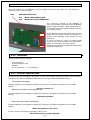
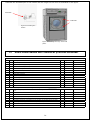
ELECTION
button
Graphical
DISPLAY
ECO
button
START - STOP
button
MODE
button
Enter
Button
Figure 3 View of control panel
MINUS
button
PLUS button
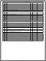
Cycle in progress and standard display.
During functioning the appliance displays the
number of the washing cycle selected, the
number and comment relative to the specific
phase in progress and the icons that indicate,
as described below, the activation of the
various functions such as heating and load/
unload of water from the tub.
The display changes at regular intervals,
indicating the estimated time remaining to the
end of the washing cycle for a few seconds.
Press the MODE button with the washing cycle in progress: the display changes to the following
one and indicates the functional parameters if the drying cycle in progress.
Program
number
Number and description of the phase in
execution.
Heating on
Appliance loading
water for filling
Total litres
loaded up to
updated in
real time.
With litre
counter only.
ECONOMY
function
inserted
symbol
Instant temperature.
Temperature
to reach.
Instant water level in
the tub.
31
Water level
envisioned in the tub
Press the MODE button to pass to the following displays.
Successive pressing of the MODE button takes the display to initial conditions.
Attention!
• These modifications are not saved in the memory and therefore
on the successive execution of the washing cycle, this will start
as per original program.
• For all conditions where this is possible, the modifications to the
programmed values are made using the “+” and “-“ buttons and
are immediately active, without confirmation.
The screens are as shown below .
Read only screen.
The active water inlets are highlighted (hot, hard and soft) for the the
phase of the washing cycle in progress and how many litres of water have
been loaded up to that moment.
Read only screen.
The active water inlets at the dispenser for the phase of the washing cycle
in progress are highlighted along with how many seconds of activation
have been envisioned. At the end of activation, the amount relative to
the active condenser will be "0" but will remain highlighted to indicate its
activation.
Read only screen.
The active liquid soap pumps for the phase of the washing cycle in progress
are highlighted along with how many seconds of activation have been
envisioned. At the end of activation, the amount relative to the active
pump/s will be "0" but will remain highlighted to indicate its activation.
The OZONE injector signal just has the ON/OFF status.
Read and modify screen.
The motor activation setting is highlighted with rotation times and relative
pauses.
In the G400M version, the rotation speed in rpm can be varied with the
washing cycle in progress.
Read only screen.
The activation setting of drain 1 and optional drain 2 is highlighted. A time
different to 0sec indicates a closure delay of drain 1 or drain 2 or both.
Read only screen.
The temperature of the motor control electronic circuit is highlighted along
with its dissipator, both situated in the appliance wiring compartment. IT
IS NOT the motor temperature.
Read and modify screen. For spin phases ONLY.
The motor activation setting is highlighted with rotation times and relative
speeds.
The spin duration time can be changed.
In the G400M version, the rotation speed in rpm can also be varied with
the washing cycle in progress.
The quality of the distribution of the laundry inside the drum is expressed
via the letters A, B and C is expressed in the top right.
A = bad distribution, long acceleration ramps and maximum speed
reduced with respect to that envisioned.
B = discrete distribution, medium acceleration ramps and maximum
speed slightly reduced with respect to that envisioned.
C = excellent distribution, very quick acceleration ramps and spin speed
as per program.
32
6.3
SELF-SERVICE
Indications valid only for kg8, kg11, kg18 and kg22 models.
6.3.1 INSTALLATION OF THE EMERGENCY STOP BUTTON
On the basis of the following Standard
ISO10472-1: paragraph 5.2
The emergency stop device is facultative on the appliances envisioned for self-service.
The models set-up foe self-service, do not have an emergency stop mounted as per standard and therefore
they must be made available in the room where the appliances will be installed; proceed as follows:
•
•
•
There must be sufficient emergency stop device in the room, in a number such that
at least one is always at a minimum distance of 2 mt from the appliances.
Each emergency stop device must be positioned at a maximum distance of 8 mt
from the areas destined to the operators.
If the device consists in an emergency stop button, this must be positioned at a
height between 70 cm and 170 cm above the ground or from the platform destined
for the operators.
The emergency stop device or devices must be connected to the appliance electric power supply source in a way that on their intervention, they can remove the voltage indistinctly to all
appliances present in the room used for self-service.
33
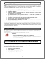
6.3.2 CARD SETTING
Using dip switch n°3 the appliance can be enabled to function by means of a mechanical or
electronic coin operated device.
DS3 APPLIANCE STATUS
ON WITH COIN OPERATION
OFF WITHOUT COIN OPERATION
The “economy” function is not available in
the coin operated versions and the ECONOMY
button input becomes “rapid advancement”.
The START button therefore assumes just the
cycle start function.
By programming from the push button control
panel, set the number of tokens necessary to
perform each washing cycle present on the
appliance.
In order to start the cycle, the board must
count just as many activations of the KGETT
input (one activation at every token).
Washing cycle start then takes place as always
using the START key.
OFF
ON
6.3.3 VERSIONS
These versions can be present:
Coin operated
Central payment unit
Stepper
N° of payments: 1 – 10 (default 3)
6.3.4 DISPLAY INDICATIONS
As well as the normal display indications in wash cycle START stand-by condition, the following
indications will also be displayed depending on the type of SELF SERVICE setting:
Coin operation with stepper
Writing displayed, with appliance waiting for payment and before activation of the START
button:
“Insert n. tokens: xx”
External coin operation or central payment unit
Writing displayed, with appliance waiting for payment and before activation of the START
button:
“Make the payment”
Electronic coin operation on the machine
Writing displayed, with appliance waiting for payment and before activation of the START
button:
“Make the payment of €:xx.xx”
In this version the following message is also given:
“the machine does not give change”.
34
6.3.5 CYCLE COST SETTING
To set the washing cost/cycle, apply voltage to the appliance with the PRGET contact closed,
which is positioned on the rear of the same.
According to the type of SELF SERVICE management activated, there may be the following
options:
Coin operation with stepper
The display shows the price (n. tokens) of the selected washing cycle with a display such as:
Pxx :(program number from 01 to 20)
Cycle cost: xx (01-10)
using the “PLUS” and “MINUS” buttons, the price can be modified (field 1...10) while using the
“SEL” button, the washing cycle can be modified.
All cycles stored in the appliance are proposed, also those that are present but not enabled.
External coin operation or central payment unit
No price can be programmed because everything is managed with the remote payment system.
The appliance is enabled for start-up with just one impulse of at least 200msec coming from the
central payment unit.
Electronic coin operation on the machine
The display shows the price and cycle selected with a display that is:
Pxx :(program number from 01 to 20)
Cycle cost: xx,xx €
Using PLUS” and MINUS the price can be modified (field variable from 0.00€ to 99.95€with
minimum steps of 0.05€) and with SEL button, the washing cycle can be modified, to which the
sale price can be applied. All cycles stored in the appliance are proposed, also those eventually
present and not enabled. To end programming,take the PRGET selector switch to “0” and remove
and re-apply voltage to the appliance.
With the coin operation function enabled, switch the appliance on, the display shows:
Or
Or
The washing cycle selected with the maximum temperature
envisioned.
The time programmed for the countdown.
“Insert n. tokens: xx”
“Make the payment”
“Make the payment of €: xx.xx”
Depending on the possible different payment method settings.
“xx” and “xx,xx” correspond to the value previously introduced, expressed as a number of
tokens or cost in €, for that particular drying cycle.
During the insertion of tokens or coins the cost of the washing cycle will reduce until on
introduction of the last token/’coin, the display indicates:
“00” flashing
The following wording appears with the door closed:
“PRESS START”
Press the START button to start the washing cycle.
With the door open, two different wordings appear:
“load the laundry”
“close the door”
On start-up of the drying cycle, the display shows the normal indications present also on
appliances that are not envisioned for self-service.
35
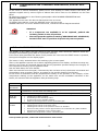
Attention!
• The number of tokens or coins already inserted and not used
remains memorised if there should be a power cut.
• The maximum credit, i.e. the maximum number of tokens counted is 10.
• The maximum credit, i.e. the maximum value that can be accumulated is 20.00€.
The residual credit can be zeroed with machine in stand-by to start the washing cycle and with the
door open, following the procedure illustrated here. This must be concluded within the maximum
time of 10 seconds:
Press the ECO key 5 times consecutively;
Press the START key 5 times consecutively;
The confirmation of zeroing of any residual credit takes place with the message covering the entire
display:
“CREDIT ZEROED”
NOTE
The 10 second count starts from the first time the ECO key is pressed.
Attention!
• Only enabled washing cycles can be carried out;
• It is not possible to access programming of optional parameters;
• It is not possible to insert a pause during the washing cycle;
• In the event of a power cut during a wash cycle, when the voltage
returns re-starts only occurs after the START button has been
pressed, without having to insert other tokens/coins.
• The optional parameters enabled before insertion of DS3 remain
active even after enabling of coin operation (except for “Cycle
delayed start”).
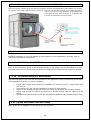
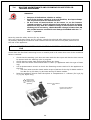
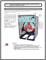
6.4
OPENING AND CLOSING THE DOOR
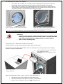
To open the door, refer to figure:
•
•
On KG 8 G400, KG 11 G400, KG 18 G400, KG 22 G400, pull the handle
On KG 33 G400, KG 40 G400, KG 55 G400 turn the handle clockwise until the handle
reaches the vertical position and faces down, now pull the door.
Figure 4 front view. KG 33 G400, KG 40
G400, KG 55 G400.
Turn the handle downwards clockwise to
vertical position and then pull the door.
Figure 5 Figure 5 front view. KG 8 G400, KG 11 G400,
KG18G400, KG 22 G400. Grip the handle and pull.
36
To close the door, refer to the figures:
•
•
KG 8 G400, KG 11 G400, KG 18 G400, KG 22 G400 approach the door to the lock
with handle pulled and then push the handle to end run (parallel to the door).
KG 33 G400, KG 40 G400, KG 55 G400 approach the door to the lock with handle in
vertical position (facing downwards) and then turn the handle anti-clockwise until it is
completely locked (in horizontal position facing the right)
Figure 7 Approach the door and push the handle.
Figure 6 Approach the door to the lock and turn the
handle anti-clockwise (keeping the door pressed)
until the horizontal position of the handle.
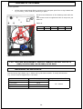
6.4.1 LOADING THE SOAP IN THE DISPENSER DRAWER
Attention!
• Use the I.P.D. devices recommended by the soap supplier when
loading the dispenser drawer. In the event of contact with the
soap, follow the indications suggested by the soap supplier.
• Only use non-foaming soap.
KG 8 G400, KG 11 G400, KG 18 G400, KG 22 G400
Lift the rubber lid to open the dispenser drawer and load the soap.
KG 33 G400, KG 40 G400, KG 55 G400 Turn the dispenser door closing hook and accompany
the door, turning it downwards.
Figure 8 WFM 33KG 33 G400, WFM 40KG 40
G400, WFM 55KG 55 G400.
Turn the door hook and accompany the door
downwards.
Figure 9 kg8 - kg22
Lift the rubber lid.
When the dispenser drawer is open, load the soap depending on:
•
•
•
indications of the soap supplier (quantity and type)
indications stated on the label of the item to be washed
type of cycle selected (if with pre-wash, washing, etc.)
37
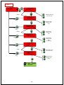
Refer to the following figures to load the soap.
Dispenser drawer.
KG 8 G400, KG 11
G400, KG 18 G400, KG
22 G400
A
B
C
Soap for cycles with
prewash and/or soak
Soap for cycle with
washing
Softener
Powder soap only
Powder soap only
Liquid soap only
Dispenser drawer.
KG 33 G400, KG 40
G400, KG 55 G400
A
B
C
Soap for cycles with
prewash and/or soak
Soap for cycle with
washing
Softener
Powder or liquid soap
Powder or liquid soap
Powder or liquid soap
KG 33 G400, KG 40 G400, KG 55 G400
The soap containers can be extracted from the drawer and used to be loaded more comfortably
from the soap container.
When the soap has been loaded, put the soap container back in the dispenser drawer, paying
attention that it remains in a horizontal position.
Close the dispenser drawer and block it using the hook.
Attention!
• If one of the 5 soap containers is missing, do not use the appliance!
• Do not introduce more soap than that suggested by the supplier.
• Excess soap contributes to increasing environmental pollution,
worsening washing efficiency.
• Excessive hypochlorite concentrations an case oxidation of the
metal parts also if not in direct contact with the same.
• Keep the powder soap away from possible contact with water.
• Incorrect concentrations of soaps or additives used during the
washing phases can reduce the life span of the appliance and its
performance.
• Keep the soap in a closed cabinet and out of the reach of
unathorised persons.
• Always keep the technical cards relative to the soaps used on
hand.
38
6.5
RECOMMENDATIONS FOR USING THE APPLIANCE
The nominal laundry load means carried out with dry laundry and in compliance with the Standard
ISO 9398-4:2003.
For resistant fabrics such as cotton or linen, the use of the nominal load is recommended, while
for delicate-synthetic fabrics, the use of ahalf load is recommended.
The amount of soap to be used must be recommended by the supplier of the same depending on
the hardness of the water used.
Where it is not strictly necessary, it is recommended to carry out cycles with reduced water load
and heating temperature in order to decrease appliance water and energy consumption, with
consequent reduction of execution times of the cycle itself.
Attention!
• Do not touch the door glass as during functioning it can reach
90°C.
39
6.5.1 SYMBOLS (LABEL) APPLIED TO THE FABRICS
Symbols
Basic symbols
Washing: the tub is the symbol for washing.
Chlorine bleach: the chlorine bleach symbol is a triangle.
Ironing: for ironing the symbol is the shape of an iron.
Professional textile care.
Professional washing.
Tumble drying: A square containing a circle is the symbol for tumble drying.
Symbols
Basic symbols
Treatment not allowed: as well as the previous symbols, St. Andrew's cross positioned on the symbol
means that the treatment expressed by that particular symbol must not be performed.
Moderate treatment: as well as the 5 symbols, the bar under the tub or the circle indicates that the treatment must be carried out moderately with respect to the treatment corresponding to the same symbol
without bar.
Very moderate treatment: as well as the 5 symbols, the interrupted bar under the tub indicates a very
moderate washing treatment.
Symbols
Additional symbols
Maximum temperature: 95°C.
Normal machine action.
Normal rinse.
Normal spin.
Maximum temperature: 95°C.
Gentle machine action.
Cool down rinse (due to gradual introduction of cold water).
Short spin.
Maximum temperature: 70°C.
Normal machine action.
Normal rinse.
Normal spin
Maximum temperature: 60°C.
Normal machine action.
Normal rinse.
Normal spin
Maximum temperature: 60°C.
Gentle machine action.
Cool down rinse (due to gradual introduction of cold water).
Short spin
Maximum temperature: 50°C.
Gentle machine action.
Cool down rinse (due to gradual introduction of cold water).
Short spin
Maximum temperature: 40°C.
Gentle machine action.
Cool down rinse (due to gradual introduction of cold water).
Short spin
Maximum temperature: 40°C.
Gentle machine action.
Normal rinse.
Normal spin.
Do not twist
Maximum temperature: 40°C.
Gentle machine action.
Normal rinse.
Short spin
40
Hand wash only.
Do not machine wash - maximum temperature 30°C.
Handle with care
Do not wash.
Handle with care when wet.
Symbols
Tumble drying
Tumble drying allowed.
Normal drying program
Tumble drying allowed.
Low temperature drying program
Do not tumble dry
Symbols
Natural Drying
Line dry. The article is dried by hanging it WET on a line after having removed the excess water.
Drip dry. The garment is hung wet, dripping, with or without re-shaping, without removing any excess
water.
Dry flat. The garment is re-shaped and dried on a flat surface after the removal of any excess water.
Dry in the shade. This symbol is placed at the side of the line drying, drip dry or flat dry symbols to indicate that the process must be performed away from the action of direct sunlight.
Symbols
Bleaching
Chlorine-based bleaching allowed only in a cold and dilute solution.
Do not use chlorine bleach.
Any oxidising agent bleach allowed.
Only oxidising bleach without chlorine allowed.
DO NOT bleach.
Symbols
Ironing
Iron at a maximum sole-plate temperature of 200°C.
Iron at a maximum sole-plate temperature of 150°C.
Iron at a maximum sole-plate temperature of 110°C.
Steam ironing may be risky.
Do not iron. Steam ironing and treatments are not allowed.
Symbols
Professional textile care.
Dry cleaning in all solvents normally used for dry cleaning including the solvents indicated for P symbol as
well as trichloroethylene and 1.1.1. trichloroethane.
Dry cleaning with tetrachloroethylene, monofluorotrichloromethane as well as all solvents indicated for F
symbol.
Normal washing treatments, without restrictions.
41
Dry cleaning using solvents indicated in previous point.
Strict limitations on the addition of water and/or mechanical action and/or temperature during cleaning
and/or drying.
Self-service cleaning is not allowed.
Dry cleaning with trifluorotrichloroethane, hydrocarbons (boiling point between 150°C and 200°C, flashpoint between 38°C and 60°C).
Normal washing treatments, without restrictions.
Dry cleaning using solvents indicated in previous point.
Strict limitations on the addition of water and/or mechanical action and/or temperature during cleaning
and/or drying.
Self-service cleaning is not allowed.
Professional washing.
Normal procedure.
Professional washing.
Delicate procedure.
Professional washing.
Very delicate procedure.
Do not dry clean.
No stain removal with solvents.
6.6
WASHING CYCLE START-UP
For the maximum load of laundry, see table below, drawn-up on the basis of the ISO9398-4:2003.
•
•
•
•
•
•
•
•
•
Check the drum is empty and clean.
Load laundry with the same mechanical features (type of fabric) and the same washing
requirements (type of dirt, colour).
Check the labels on every item and follow the indications given. Before washing any
garment, make sure that any buttons, zips, clips and buckles face inwards.
Check the pockets: they must be empty.
Load the soap ad check the amount of soap present in the liquid soap tanks: there
must be at least that necessary for the washing cycle selected.
Open the water and any steam and condensate drain/recovery gate valves (for
appliances with this type of heating).
Power the appliance. Check switch-on of the appliance display. Wait a few seconds for
the cycle selection stand-by configuration to appear on the appliance display.
Select the cycle WITH DOOR OPEN using the SEL button according to that stated on
the labels of the garments to be washed and the indications of the soap supplier.
Close the door and press the START/STOP button.
Start-up of washing cycle: follow the instructions below.
Appliance maximum load capacity (dry laundry)
kg 8 G400
kg 11 G400
kg 18 G400
kg 22 G400
kg 33 G400
kg 40 G400
kg 55 G400
8.1 kg
10.5 kg
18.3 kg
24.4 kg
37.2 kg
44.4 kg
57.5 kg
At this point the door is blocked and the washing cycle starts. When the cycle has finished, the
appliance signals program end with an acoustic message and the “open door” message appears
on the display.
42
Attention!
• The door must be opened without force; opening must be manual
and only once release has occurred does "open door" appear.
• Before opening, always make sure that the drum is at a standstill,
that the water has been drained and that the internal temperature
has dropped below 40°C.
• Do not put laundry into the machine that has been cleaned, wet,
washed or stain-removed with flammable or explosive materials.
Proceed by hand washing.
End of work: carry out the following operations.
•
•
•
•
Leave the door open.
Remove the voltage to the appliance via the master switch.
Close the hot, cold water cocks and that of the steam and condensate recovery/drain
(on the appliances with this type of heating).
Disconnect the appliance from the mains electricity.
Attention!
• Do not leave the appliance uselessly powered by the mains
electricity.
• Switch the appliance master switch OFF when the same is not
being used.
6.7
AUTOMATIC EXECUTION OF A PROGRAM
The electronic control is already supplied with some standard programs.
On pressing the START button, the electronic control performs the phases necessary for the
washing cycle selected. The basic washing cycle sequence envisions:
•
•
•
•
•
•
•
•
•
•
weighing phase
soak phase
low speed spin phase
prewash phase
low speed spin phase
washing phase
low speed spin phase
two rinsing phases with intermediate low speed spin
final rinsing phase with final maximum speed spin
unrolling phase.
Attention!
• One or more phases may not be present on all programs!
Every phase has a drum movement action, water level and dedicated temperature for the type
of textile to be handled.
43
6.8
DESCRIPTIONS OF THE STANDARD PROGRAMS SUPPLIED WITH THE
APPLIANCE
Table 15
Cycle 1: Very soiled whites
Phase Cycle 6: Terry cloth
Phase
Weighing
45
Weighing
45
40°C prewash with energetic wash action, low level, 6' washing after temperature reached, small tank A loading 30",
pump 1 enabled 15"
11
40°C prewash with gentle wash action,
25
medium level, 8' washing after temperature reached, small tank A loading 30",
pump 1 enabled 15"
Short 500 rpm spin for 90 seconds
4
Short 500 rpm spin for 90 seconds
4
90 °C wash with energetic wash action,
low level, 10' washing after temperature
reached, small tank B loading 30", pump
2 enabled 15" cooling at 55°C.
5
60 °C wash with gentle wash action,
medium level, 10' washing after temperature reached, small tank B loading
30", pump 2 enabled 15"
22
Short 500 rpm spin for 90 seconds
4
Energetic rinse, medium level, 2’ washing 16
Delicate rinse, medium level, 2’ washing 17
Short 500 rpm spin for 90 seconds
Short 500 rpm spin for 90 seconds
4
4
Energetic rinse, medium level, 2’ washing 19
Delicate rinse, medium level, 2’ washing 18
Short 500 rpm spin for 90 seconds
4
Short 500 rpm spin for 90 seconds
Energetic rinse, medium level, 3’ washing, tank C loading 30”, pump 3 enabled
15”
21
Delicate rinse, medium level, 3’ wash20
ing, tank C loading 30”, pump 3 enabled
15”
Final spin at 1000 rpm 100 seconds
1
Final spin at 1000 rpm 100 seconds
1
Unrolling 90”
23
Unrolling 90”
23
Cycle 2: soiled whites
Phase Cycle 7: delicate with soak
Phase
Weighing
45
45
Weighing
4
40°C soak with delicate movement, high 3
level, 10’ washing after reaching temperature, pump 1 enabled for 15”
40°C prewash with energetic wash action, low level, 8' washing after temperature reached, small tank A loading 30",
pump 1 enabled 15"
13
40°C prewash with energetic wash ac11
tion, low level, 6' washing after temperature reached, small tank A loading 30",
pump 1 enabled 15"
Short 500 rpm spin for 90 seconds
4
Short 500 rpm spin for 90 seconds
4
60 °C wash with energetic wash action,
low level, 10' washing after temperature
reached, small tank B loading 30", pump
1 enabled 15"
10
40 °C wash with energetic wash action,
low level, 6' washing after temperature reached, small tank B loading 30",
pump 2 enabled 15"
9
Short 500 rpm spin for 90 seconds
4
Short 500 rpm spin for 90 seconds
4
Energetic rinse, medium level, 2’ washing 16
Energetic rinse, medium level, 2’ washing
16
Short 500 rpm spin for 90 seconds
Short 500 rpm spin for 90 seconds
4
Energetic rinse, medium level, 2’ washing 19
Energetic rinse, medium level, 2’ washing
19
Short 500 rpm spin for 90 seconds
4
Short 500 rpm spin for 90 seconds
4
Energetic rinse, medium level, 3’ washing, tank C loading 30”, pump 3 enabled
15”
21
Energetic rinse, medium level, 3’ wash- 21
ing, tank C loading 30”, pump 3 enabled
15”
4
44
Final spin at 1000 rpm 100 seconds
1
Final spin at 1000 rpm 100 seconds
1
Unrolling 90”
23
Unrolling 90”
23
Cycle 3: soiled coloureds
Phase Cycle 8: very soiled with soak
Phase
Weighing
45
45
Weighing
40°C soak with delicate movement, high 3
level, 10’ washing after reaching temperature, pump 1 enabled for 12”
40°C prewash with energetic wash action, low level, 6' washing after temperature reached, small tank A loading 30",
pump 1 enabled 15"
11
60 °C wash with energetic wash action,
low level, 10' washing after temperature reached, small tank B loading 30",
pump 1 enabled 15"
10
Short 500 rpm spin for 90 seconds
4
Short 500 rpm spin for 90 seconds
4
40 °C wash with energetic wash action,
low level, 6' washing after temperature
reached, small tank B loading 30", pump
2 enabled 15"
9
90 °C wash with energetic wash action,
medium level, 10' washing after temperature reached, small tank B loading 30", pump 2 enabled 15" cooling at
55°C.
5
Short 500 rpm spin for 90 seconds
4
Short 500 rpm spin for 90 seconds
4
Energetic rinse, medium level, 2’ washing 16
Energetic rinse, medium level, 2’ washing
16
Short 500 rpm spin for 90 seconds
Short 500 rpm spin for 90 seconds
4
Energetic rinse, medium level, 2’ washing 19
Energetic rinse, medium level, 2’ washing
19
Short 500 rpm spin for 90 seconds
4
Short 500 rpm spin for 90 seconds
4
Energetic rinse, medium level, 3’ washing, tank C loading 30”, pump 3 enabled
15”
21
Energetic rinse, medium level, 3’ wash- 21
ing, tank C loading 30”, pump 3 enabled
15”
Final spin at 1000 rpm 100 seconds
1
Final spin at 1000 rpm 100 seconds
1
Unrolling 90”
23
Unrolling 90”
23
Cycle 4: delicate coloureds
Phase Cycle 9: soiled with soak
Phase
Weighing (on KG 8-11-18-22 )
45
Weighing
45
Delicate cold prewash, medium level,
5’ washing, tank C loading 30”, pump 1
enabled 15”
14
40°C soak with delicate movement, me- 12
dium level, 10’ washing after temperature reached
25°C wash with gentle wash action, medium level, 5' washing after temperature
reached, small tank B loading 30", pump
2 enabled 15"
7
40°C prewash with energetic wash ac11
tion, low level, 6' washing after temperature reached, small tank A loading 30",
pump 1 enabled 15"
Short 500 rpm spin for 90 seconds
4
Short 500 rpm spin for 90 seconds
4
Delicate rinse, medium level, 2’ washing.
17
90 °C wash with energetic wash action,
low level, 10' washing after temperature reached, small tank B loading 30",
pump 2 enabled 15" cooling at 55°C.
5
Delicate rinse, medium level, 2’ washing.
18
Short 500 rpm spin for 90 seconds
4
Delicate rinse, medium level, 3’ washing,
tank C loading 30”, pump 3 enabled 15”.
20
Energetic rinse, medium level, 2’ washing
16
Final spin at 800 rpm 100 seconds
2
Short 500 rpm spin for 90 seconds
4
Unrolling 90”
23
Energetic rinse, medium level, 2’ washing
19
4
45
Cycle 5: very delicate items
Phase Short 500 rpm spin for 90 seconds
Weighing
45
Energetic rinse, medium level, 3’ wash- 21
ing, tank C loading 30”, pump 3 enabled
15”
4
Delicate cold prewash, medium level,
1’ washing, tank C loading 30”, pump 1
enabled 15”
15
Final spin at 1000 rpm 100 seconds
1
25°C wash with gentle wash action, medium level, 5' washing after temperature
reached, small tank B loading 30", pump
2 enabled 15"
7
Unrolling 90”
23
Delicate rinse, medium level, 2’ washing
17
Cycle 10: rinse and spin
Phase
Delicate rinse, medium level, 2’ washing
18
Energetic rinse, medium level, 3’ wash- 21
ing, tank C loading 30”, pump 3 enabled
15”
Delicate rinse, medium level, 3’ washing,
tank C loading 30”, pump 3 enabled 15”
20
Final spin at 1000 rpm 100 seconds
1
Final spin at 500 rpm 90 seconds
24
Unrolling 90”
23
Unrolling 90”
23
Attention!
KG 8 G400, KG 11 G400, KG 18 G400 and KG 22 G400
• The washing programs from n° 11 to n°19 are identical to washing
cycles from 1 to 9 without the initial weighing phase.
• The minimum water level in the drum is electronically fixed at 4
cm.
KG 33 G400, KG 40 G400 e KG 55 G400
• The washing programs are from 1 to 10 and always without
weighing, not possible on these models.
• If the appliance has been re-programmed via PC or from the
keyboard or several special functions have been activated, do not
refer to table 15.
• The manufacturer reserves the right to modify the features of the
pre-loaded programs at any time.
• The minimum water level in the drum is electronically fixed at
22cm.
46
6.8.1 WEIGHING FUNCTION
The appliance is fitted with a particular patented function that allows to measure how many
kilograms of fabric are loaded in thedrum.
The weighing function takes place in automatic mode and the operator must only load the laundry,
which must be dry, select the desired washing program (from 1 to 9 with weighing), close the
door and press the “START / STOP” button.
The weighing procedure has duration of about 1 minute and cannot be by-passed via the START
button.
The quantity of water, soap and the washing speed normally set are halved if the drum is empty.
The nominals remain if the drum load measured corresponds with the capacity of the appliance.
All intermediate load levels are proportional.
Attention!
• Carrying out a cycle without laundry means seeing the water
level in the tub halved and a very slow drum rotation speed!
• To change the automatic weighing and to set it in manual, the
•
•
•
6.9
settings must be changed via the PC connection and the relevant
software or with 16kB smart card,. Contact the after-sales service
for further details.
The weight value read from the appliance is never shown on the
display in the automatic weighing procedure. This only takes
place in the event of the manual procedure.
The weighing function detects the weight of the loaded laundry
and therefore if this is wet, the value is falsified.
The weighing function requires taring every 50 cycles performed
with weighing. Follow that stated below for the tare operation.
CALIBRATION OF THE DWS SYSTEM
Attention!
• Every 50 cycles the display show a message that calls the
operator's attention to perform calibration.
Perform the operations summarised here in sequence:
1.Empty the drum completely;
2.Switch theappliance on;
3.Keep the door open;
4.Press the START button 10 times quickly and consecutively;
5.The calibration procedure starts;
6.Close the door;
7.Press the START button.
The appliance carries out the complete calibration procedure autonomously.
This operation reduces water and electric consumption of the appliance.
47
6.10 SECONDARY FUNCTIONS
At least one of the following conditions is required in order to change temperatures, levels and
times of the individual phases:
•
•
•
Have a smart card programmed with the necessary modifications (previously
programmed via request to the technical after-sales service);
Personal computer with WipWizard installed as well as serial cable (attention the
serial port is optional on WF8G400, WF11 G400 and WF18G400);
To have the G400M programmer, programmable from keyboard (standard for KG
22 G400, KG 33 G400, KG 40 G400, KG 55 G400).
A RS232 serial port is installed for programming via PC.
For the activation of the “data transmission and reading” mode, the appliance must be
switched on using the “MODE” button, holding it down until the display shows the “WIZARD”
indication and the icons of a PC and the appliance connected.
For further information:
•
•
Contact the dealer or the technical assistance service.
Consult the manual accompanying the programming via PC software.
Attention!
• Do not try to read or program the appliance if you are not in
•
possession of the appropriate serial cable and WipWizard
application installed in the PC: the operation could damage the
circuit boards.
Contact the dealer or the after-sales service if appliance
programming must be modified. The serial cable, the application
to install in the PC and the instructions to make the requested
modifications will be supplied.
To modify programs, parameters, etc. of the’appliance via Smart card, refer to figure 35.
The appliance has a smart card with which it is possible:
•
•
To update the control electronics firmware with two 128kB smart cards.
To modify programs and parameters (software) with 16kB smart card.
If you are interested, contact the dealer or after-sales service and supply details regarding the necessary modifications.
The smart card will be sent with the relative instructions for use. The optional is on the
price list.
Attention!
• Do not try to read or program the appliance using the smart cards
that are different to the original ones (cash card, credit card,
video hire card etc.) as it would be damaged irreparably. The
manufacturer is NOT liable for incorrect and improper use of the
smart card reader present in the appliance.
48
6.10.1INTRODUCTION TO THE PROGRAM
The structure of the washing cycles is defined by the manufacturer on the basis of most
market requests It is however possible with this manual:
•
•
G400 control: to change the options (KG 8 G400, KG 11 G400, KG 18 G400).
G400M control: to change all data of the individual functions in terms of level,
duration, temperature, etc. (kg 8 G400, kg 11 G400, kg 18 G400, kg 22 G400, kg
33 G400, kg 40 G400, kg 55 G400).
During the execution of the washing cycle, it is possible to display some information regarding
the phase in progress and several parameters can be changed (on conclusion of the phase,
all modified parameters will go back to their original value) while the options or data of the
individual phases can be modified only with appliances in stand-by for cycle start (door
open). When modified they will remain as such until a new modification.
G400 CONTROL
It is possible to modify several options of the individual cycles such as:
•
•
•
•
•
•
Modify the spin, exclude it or change duration (the speed can also be changed in the
G400M control).
Enable or disable the prewash, the undesired washing cycles, the buzzer , the cooling
function.
Set a delayed washing cycle, to be re-set every time necessary.
Reduce the temperature of all washing cycles by 10°C.
Change the heating hysteresis or the basic level at which the soap pumps are activated (if connected).
Change the display off the time remaining to the end of the cycle or display mode of
the washing cycle temperature.
Attention!
• Some options, even if enabled, may not be envisioned.
Therefore, they will not be performed (cooling on cycles with low
temperature is not envisioned therefore even if enabled it will
not be performed).
G400M CONTROL
It is possible to modify all parameters of the individual operations performed in addition to that
described for the G400 control.
In order to make modifications, consider that every program is made up from a group of phases
put into sequence that can be recalled several times in the same washing cycle but, most of all,
they can be used on several washing cycles.
The modifications can be made to the washing cycle (different phases inserted or others cancelled) or to the phases (change level, duration, temperature, etc.) but every modification
carried out on a phase means that all cycles that use this phase are modified.
49
PROGRAMMING LIMIT FOR G400 AND G400M
20 washing cycles.
The library is made up of a maximum of 45 phases (of which 1 is forcedly the pressure).
At maximum, a washing cycle is made up of 19 phases.
6.11 SYMBOLS OF THE ICONS USED IN OPTIONS AND PROGRAMMING
MODIFICATIONS
Symbol
Name
Description
START/STOP
Cycle start button, forced advancement button of the washing cycle and
cycle end. Used in the “comments” text to delete the character selected.
MODE
Button used to enter and escape the menu address, escape without confirming variations or display information during execution of the program.
ECO
Button used to reduce the amount of water of the selected washing cycle
(only if without weighing).
MINUS
Button used to change item in the menu, decrease the value displayed, shift
to the left in the texts or comments.
PLUS
Button used to change item in the menu, decrease the value displayed, shift
to the right in the texts or comments.
ENTER
Button used to confirm the value displayed, enter the menu item displayed
or confirm the character to be modified.
SEL
Button used to select the program (with door open) or select the letters (if
texts, comments or maintenance technician name are inserted).
DISPLAY
The background colours used in this manual are only to help to understand the part of the
menu in progress. The display on the appliance is always green with the text, icons and all
parameters in black.
6.12 INSERT THE VARIOUS FLOW DIAGRAMS HERE
For immediate understanding of the instructions, these are displayed with flow diagrams.
Attention!
• If voltage should be missing during the modify MACHINE, SERVICE, CYCLES, PHASES PARAMETERS, the data is not stored and
the procedure must be repeated from the start.
50
APPLIANCE SWITCH-ON AND RELATIVE BASIC FUNCTIONS
A beep is heard every time the button is pressed. At the end of the washing cycle the appliance
emits a sequence of beeps for 15 seconds.
This sequence can be interrupted by pressing the – “ (minus) button. it is also possible to completely eliminate buzzer functioning if it is not necessary.
Setting on the relative BUZZER item in the MACHINE PARAMETERS menu.
Attention!
ECONOMY FUNCTION
• This function simply reduces the amount of water and soap load
normally envisioned by the manufacturer.
• It is not to be intended as the “½ load button”.
• It is only active in the cycles without weighing.
• The ECONOMY function reduces the water level in the tub and
the reduction corresponds to a value of 20%, but this can be
modified.
6.12.1 MODIFICATIONS AND DISPLAYS DURING THE PERFORMANCE OF A
PROGRAM
The washing cycle duration time displayed is programmed in “self-learning”” mode i.e. at every
washing cycle the appliance measures the real time passed fro when the START/STP button was
pressed up to the end of the washing cycle and re-proposes the time measured and updated on
the next selection.
In the event of forced advancement of the washing cycle via the START/STOP button, this time
is forcedly falsified. The appliance will perform the phases in the correct sequence even if the
time displayed is 00:00.
Attention!
• This washing cycle duration times are not however to be
considered restricting for the performance of the cycle.
• They are used only to give a maximum indication. In fact, the
•
•
duration of the cycle depends on different factors that can vary
every time (amount of laundry loaded, temperature of the water
loaded, etc.).
During the PAUSE function, all functions are temporarily
suspended, the water is not drained and the door remains blocked.
The time self-learning function does not consider the duration of
the pause inserted.
It is possible to change some functions during the execution of the program, such as:
Proceed as follows.
•
•
•
•
Water level in the tub;
The temperature of the water in the tub;
The maintenance time;
The drum rotation speed.
Pressing the mode button again or during the different Soak, Prewash,
Washing or Rinsing, Spin phases it is only possible to consult the information available.
•
Pressing the MODE button while loading the water into the tub. The load water level
can be changed (via the plus or minus keys);
51
•
•
•
Pressing the MODE button while heating the water in the tub. The heating temperature
can be changed;
Pressing the MODE button during the countdown that determines the duration of the
phase. The phase time can be changed;
Pressing the MODE button during drum rotation. The drum speed can be changed.
NOTE.
All water level, temperature, time variations are performed by action on the
PlUS and MINUS buttons.
6.12.2APPLIANCE PARAMETERS MENU
With the door open and pressing the mode button, enter optional programming (APPLIANCE
PARAMETERS). From this menu it is possible to:
•
•
•
•
•
•
•
•
•
•
•
•
•
Not carry out cooling (if envisioned in the cycle sequence).
Change the time (but not the speed) of the final spin (the value is expressed as a
percentage of the nominal time of the final spin)
Not carry out prewash (if envisioned in the cycle sequence). Any spin after the prewash
will also not be performed.
Perform a delayed start-up (the function and time desired are enabled). On exiting
programming, on pressing the START button, the countdown will begin. This function
must be reset every time it has to be activated.
Disable the buzzer.
Remove 10 °C of heating (on all cycles and phases) by selecting “reduced”.
Enable/Disable the cycles (in the event of disabling they will be hidden not deleted).
Stop the drum during loading and draining of water.
Change the heating hysteresis.
Change the activation limit of the liquid soap load pumps (only if connected). The
minimum level depends on the appliance version. The level must never exceed the
washing level.
“Force” draining at the end of every phase.
Set the washing cycle temperature to be displayed as dummy, real or set.
Set fixed arbitrary washing cycle execution display in self-learning or real mode.
52
6.12.3SERVICE MENU
Press the MODE button with door open and then press the PLUS button to display the SERVICE
menu.
A first level password is required to access the SERVICE menu. The factory setting of the same is
pressing the ECONOMY button six times. From this menu it is possible to:
•
•
•
•
•
•
•
•
•
•
•
•
Set the functioning language (9 languages available)
Change the unit of measurement of the temperature (degrees Centigrade or Fahrenheit).
Lengthen draining time.
Change the password.
Display the appliance log, such as water and electricity consumption divided by totals
and last washing cycle performed.
Set the start message (“large” comment is displayed in the top part of the display on
ignition, “small” in the lower part, both with maximum of 16 characters).
Verify the block status of the appliance.
Test all appliance functions.
Change the times relative to the water draining (E2) and heating (E4) alarms
Set the economy button action percentage button (ECO).
Set the heating with real temperature 10°C lower.
Check the last 10 alarms occurring, with indication of the washing cycle and the phase
when the event took place.
In order to be displayed, the other menu parameters (SPIN MOTOR, MACHINE TYPE, PASSWORD 2,
CONVERSION, COIN OPERATED, WATER LOAD, MAINTENANCE, TARE CYCLE, DOOR TYPE) require
a different password (password 2), which is only available to service technicians and not generally
necessary for after-sales assistance.
6.12.4TEST CYCLE
The appliance electronics envision a TEST cycle in order to verify all functions available during a
washing program.
Follow the blocks diagram to identify how to perform the test cycle.
Attention!
• Carry out the test cycle always with drum empty.
• The test cycle must only be performed by an enabled technician
or an informed person.
6.12.5CYCLES MENU (ONLY WITH G400M ELECTRONIC PROGRAMMER)
With G400M, by pressing the MODE button with door open, the sequences of the phase that make
up the washing cycles can be changed.
In particular, from the CYCLES menu it is possible:
•
•
•
•
•
Replace one phase with another.
Delete a phase.
Insert a phase after a phase selected.
Insert a phase before a phase selected.
Copy a cycle onto a different cycle.
53
6.12.6PHASES MENU (ONLY WITH G400M ELECTRONIC PROGRAMMER)
With G400 M, by pressing the MODE key with door open and then the PLUS key, the details of
the individual phases can be changed (level, temperature, duration, drum movement, etc.). In
detail, in the PHASES menu it is possible:
•
•
•
•
Disable a phase (it is cancelled and not hidden!).
If this is phase is inserted in a washing cycle, this automatically does not contemplate
it in the execution of the list of phases to perform.
Change the destination between soak, prewash, wash, rinse, spin or unrolling (on
the basis of the type of name change, all or part of the data inserted into the phase
may be lost).
In the soak, prewash, washing, rinse phases, it is possible to set:
{{ The phase name.
{{ the type of drum movement (rotation time, pause and speed)
{{ Heating temperature and temperature maintenance time
{{ Cooling and water level to maintain during this function.
Attention!
• Do not set a cooling temperature that is higher than the heating
temperature or a cooling temperature lower than the inlet cold
water. Level 1 must be at maximum the same as the previous
washing level.
{{
The water level in the tub and the time this level must be maintained, if heating
is not enabled. If the water load level is set over 99 cm, the wording on the
display changes from "cm" to "overflow". The appliance therefore loads water
for the entire maintenance time, without ever switching the inlet valves off.
The minimum water level depends on the version of appliance being
programmed (in the event of water level below the safety level, necessary at
least to cover the heating resistances) the heating function cannot take place.
It is not performed even if it is not performed.
The water load in the tub with different water valves.
Hot water inlet valve suggested in the cycles with high heating temperature.
Hard cold water inlet valve suggested for rinsing.
Soft cold water inlet valve suggested with low temperature heating or however
when there are chemical products loaded in the tub.
Loading the small tanks contained in the soap drawer.
Enable the phase end draining, particularly useful in the final spin.
{{
The liquid soap loading time (on appliances with pumps card option and pumps)
{{
{{
{{
{{
{{
{{
{{
Attention!
• Small tank A. Corresponds to the left tub in the kg 8 G400, kg
•
•
11G400, kg 18 G400, kg 22 G400 appliances, while it corresponds
to the first 2 left containers in the kg 33 G400, kg 40 G400, kg 55
G400 appliances.
Small tank B. Corresponds to the central tub in the kg 8 G400, kg
11G400, kg 18 G400, kg 22 G400 appliances, while it corresponds
to the first 2 central containers in the kg 33 G400, kg 40 G400, kg
55 G400 appliances.
Small tank C. Corresponds to the right tub in the kg 8 G400, kg
11G400, kg 18 G400, kg 22 G400 appliances, while it corresponds
to the first 2 right containers in the kg 33 G400, kg 40 G400, kg
55 G400 appliances.
54
{{
{{
{{
{{
{{
{{
{{
{{
{{
{{
{{
where it is possible to activate the pumps for a determined period of time.
The pumps from 1 to 9 are activated for the time set, starting from when the
level of water in the tub set in the “MACHINE PARAMETERS” menu is reached.
If the “Injector pump” is set with a value different to “0” seconds, it remains
powered for the entire phase, starting from when the water in the tub is at a
higher level than the safety level.
It is possible to set the activation times of the different speeds in the spin
phases:
The distribution time 1 (set minimum 10 sec. if distribution 2 is also used).
The distribution time 2 (set minimum 10 sec. if spin 1 is also used).
The spin time 1 (set minimum 70 sec. if spin 2 is also used).
The spin time 2 (set minimum 40 sec. if spin 3 is also used).
Spin time 3 (do not set times longer than 300 sec.).
Longer times have no impact on the extraction capacity result of the water.
The maximum number of re-starts if unbalancing is detected
If start-up is to be performed with water in the tub, useful for improved balancing
of the load before the spin starts. The previous phase must however have the
"phase end draining" disabled.
{{
The following can be set in the unrolling phases:
The duration of the phase.
{{
the type of drum movement (rotation time, pause and speed)
{{
{{
A phase can be copied instead of another one using the COPY IN or COPY FROM
controls.
Attention!
• A storage confirmation of the modifications made is requested at
the end of any phase modification made.
• Press the ENTER button to store
• Press the PLUS or MINUS button to escape without saving!
• Phase 45 is exclusively dedicated to the weighing function that is
not performed by the KG 33 G400, KG 40 G400 and KG 55 G400
models appliances and can only be inserted as first phase on
every washing cycle.
55
6.12.7PRESET OPERATION
Attention!
• If the preset procedure is performed incorrectly, faults and
malfunctioning can be caused.
• It must be performed by an enabled technician or informed
person.
• This procedure eliminates all modifications and any special
programs installed on the appliance. Reset all standard values
and programs by returning to the factory configuration.
6.13 FUNCTIONS/EXCEPTIONAL SITUATIONS
In the event of a power cut during the execution of a program, the appliance stops in safety
until the power supply is restored.
Attention!
• The water in the tub flows into the drain and the door remains
blocked.
When the power supply voltage returns the, appliance performs countdown and “power fail”
appears on the display.
At the end of the countdown the appliance displays the “START ?” message.
Press the START/STOP button to re-start.
The washing cycle re-starts from the beginning of the phase in which the power cut occurred.
During the functioning of the appliance the functioning conditions are monitored constantly with
the indication of an alarm code if an anomaly is detected. The code is “E” followed by a number.
For safety reasons the door is released with a delay of 90 seconds with respect to the display of
the alarm itself.
After 5 min. the alarm displayresets automatically but the event remains memorised.
If the cause that generates the anomaly persists, on appliance switch-on or on re-start of the
washing cycle (the operator must press the START button again) the anomaly signal will be
present again
6.13.1ABORT PROGRAM IN THE EVENT OF ANOMALIES
Attention!
• The alarms generated by motor management and the inverter,
•
request a long time in order to be reset, therefore do not switch
the appliance back on immediately. Wait at least 5 minutes.
Appliance switch-on before the 5 minutes envisioned can lead to
the alarm being signalled again as time has not been given to the
components to cool down and/or discharge.
56
After 5 minutes, release the door (refer to the relevant paragraph) and power the appliance
again using mains voltage.
The “power fail” message will appear on the display and the appliance will go back to normal
display after a few seconds.
6.13.2DOOR RELEASE IN EMERGENCY
Door closed/open condition
Thedoor opening and closing operation takes place via operator intervention, who uses the handleto open
and close.
Door locked/released condition
The door lock and release operation dell takes place via the electric lock that is controlled electronically by
the G400 electronic control.
The door is blocked, therefore the operator cannot open the door using the handle.
The door released state can only take place in two conditions:
1) At the end of the washing cycle the electronic control releases the door and opening is possible by
theoperator.
2) For emergencies via the manual release device. See the warnings below.
Attention!
• Door release can be forced.
• Follow the instructions stated in this paragraph and before
proceeding with release, check the following conditions:
{{ Drum at standstill.
{{ Water drained completely.
{{ Internal temperature below 40°C.
{{ Switch the isolating switch off.
KG 8 G400, KG 11 G400, KG 18 G400 and KG 22 G400 DOOR RELEASE
The handle is released and the door can be re-opened.
Refer to figure 47 to identify the release cord.
If there is a power cut during the execution of a washing
cycle, the door opening handle remains blocked. To
release the handle, remove the front service panel and
pull the emergency release cord, positioned on the lower
left corner, downwards.
Figure 10 Door manual release.
Blocked lock release cord
57
KG 33 G400 , KG 40 G400 , KG 55 G400 DOOR RELEASE
If there is a power cut during the execution of a program, the door opening handle remains blocked. To release
the handle, insert a flat head screwdriver with max. diameter 5.5 mm into the hole in the rubber protection
near to the lock and press delicately (horizontally) and
then open the door. Refer to figure 11 to identify the
hole for introduction of the screwdriver.
Screwdriver
Figure 12 Hole
on lock to release
handle
Figure 11 Door release
mechanism.
6.14 SIGNS TO OBSERVE
Different messages or icons can appear on the display. For the identification of these, refer to
the points highlighted successively.
6.15 INDIVIDUAL PROTECTION
Refer to the indications given in the technical sheets of the soaps used for identification of the
individual protection devices during movement or loading of the soaps into the dispenser drawer.
6.16 OPTIONAL MODULES, ADDITIONAL
The following optional modules can be requested for the appliances, which increase the performance
of the appliance in terms of control versatility:
•
•
•
•
•
Liquid soap pumps control board kit. Possibility of controlling up to 5 soap pumps with
just one kit.
A maximum of 2 kits can be installed for a total of 9 soap pumps.
Both kits are standard supply of the KG 33 G400, KG 40 G400, KG 55 G400 models.
Liquid soap pumps kit (specify the amount of pumps desired and the capacity of the
same).
Serial port for communication with PC (standard for appliance with G400M programmer).
6.16.1QUICK REFERENCE INSTRUCTIONS
Refer to the block diagrams for the execution of a program.
58
6.16.2DISPOSAL OF WASTE
When the appliance is no longer to be used, it must be made non-operational, eliminating the
materials and keeping that already stated in the paragraph “ Putting the product out of service”
paragraph in mind.
In compliance with the Standards regarding disposal of waste that are in force in the individual
countries and for respect of the environment in which the appliance is installed, all appliance parts
must be divided in a way that they can be disposed of separately or appropriately recovered.
All parts making up the appliance are assimilable to solid urban waste with exception of metal
parts, which however, are not listed among special waste in most European countries.
USER INFORMATION
For the purpose and effects of Directives 2002/95/CE, 2002/96/CE and
2003/108/CE, relative to the reduction of use of dangerous substances
in electric and electronic appliances, as well as the disposal of waste” the
crossed-bin symbol on the appliance indicates that the product must be
collected separately from other waste at the end of its useful life.
The separate collection of this appliance at the end of its life is organised and
managed by the manufacturer.
If a new appliance is purchased, the user that wants to dispose of this
appliance must therefore contact the manufacturer and follow the system
that the latter uses to allow separate collection of the appliance at the end
of its life. The adequate separate collection for the successive start-up of the
appliance to be re-cycled, treatment and environmentally compatible disposal
contributes to preventing possible negative effects on the environment and
favours the re-cycling of materials that make up the appliance. Abusive
disposal of the product by the user leads to the application of administrative sanctions envisioned
by the Standards in force.
Refer to the WEEE European Directive regarding the recovery of parts (only for countries that are
part of the European Community).
Attention!
• When the appliance is put out of service, remember to remove dismantle the door!.
If it possible to dismantle the individual parts and take them to a differentiated collection centre,
refer to the cataloguing groups of the individual parts.
If required, the cataloguing groups can be found in the website: www.euwas.org
59
7.MAINTENANCE AND CLEANING
Maintenance is divided into five different levels:
Corrective or necessary maintenance
Call-out intervention due to fault or sudden malfunctioning.
Routine maintenance
It has the purpose of preserving the efficiency and safety of the appliance.
Preventive maintenance
Intervene on the appliance in advance to prevent faults or malfunctioning on the basis
of the manufacturer's experience.
Improval maintenance
Generally, adaptation for improving the protection rating of the appliance or adaptation
to the amended Standards in force.
Extraordinary maintenance
All important modernisation interventions aimed at prolonging the life span of the
appliance or the efficiency of the same, without modifying the functional features and
the structure of the appliance.
The first three types of maintenance must be considered normal activities, which an appliance
may and should undergo.
In the last two types of maintenance instead, significant variations can be made to appliance
functionality. Repercussions ’occur at a Standards and legislative point of view, which must be
taken into consideration.
Any improvement or extraordinary maintenance must be performed by authorised after-sales
centres or by duly trained personnel.
All maintenance interventions not included in this manual exclude all liability of the manufacturer,
which considers itself foreign to any possible repercussion of a legal character.
7.1
SAFETY PRECAUTIONS
All appliances must undergo regular technical maintenance and all defects detected, which can
jeopardise the worker's health and safety, must be eliminated as soon as possible. All staff
involved in the maintenance ad repair operations must be specifically qualified for these tasks.
Attention!
• Before any maintenance operation, remove the voltage to the
•
•
•
appliance and isolate all other power sources such as steam/
condensate drain or gas.
Check the drum is at a standstill.
Check that the internal temperature is below 40°C.
Check there is no water in the tub before opening the door.
60
The personnel assigned to maintenance of the appliances at any of the 5 levels envisioned,
must be in possession of all the information necessary for the correct performance of the task
assigned.
This manual supplies an important part of the information as well as the specific instructions
supplied with the new component that replaces the equivalent faulty element.
Pay attention to all signals and follow all specific requests from the suppliers of the products
necessary for cleaning and maintenance of the appliance. Read the instructions attached to
these products and comply with the indications relative to the individual protection devices.
7.2
SAFETY FUNCTIONS WITH WHICH THE APPLIANCE IS SUPPLIED
Attention!
• The appliance is supplied with the safety devices listed below.
•
•
•
•
•
•
•
•
•
•
•
•
Door closed detection micro switch.
Door blocked detection micro switch. Cuts off the power supply to the auxiliary circuit,
stopping the appliance.
“Air-Break” system in the soap drawer. Prevent the pollution of the water network in
the event of depressions.
Drain valve normally open. If there is a power cut from the electric mains, the water
is drained immediately.
Unbalancing micro switch. Reduces mechanical damage to a minimum in the event of
incorrect/anomalous loads of laundry.
Heating resistances equipped with thermo-fuse. The electric power supply is cut-off
in the event of an anomaly.
Mushroom-shaped button. Allows to interrupt the cycle in the event of an emergency.
Water level in tub sensor:
{{ Do not power the heating in the presence of insufficient water.
{{ Do not allow spinning until the water has been drained completely.
{{ Check if the water level is too high.
Temperature sensor. Control the temperature of the water.
Micro switch on the dispenser drawer door. Interrupts the water load if opened during
the washing cycle (only on kg 33 G400, kg 40 G400 and kg 55 G400).
Inverter. Regulates motor speed, checks an protects the motor and itself from
malfunctioning, such as: excessive temperatures of the circuits or heat dissipators,
overcurrents, short circuits, etc.).
Drain for "overflow" device. It is a pipe on the rear of the tub which, in the event of
malfunctioning of the waster load valves, drains the excess water directly into the
drain pipe, by-passing the discharge valve and preventing flooding (anti-overflow
function)
61
7.3
MAINTENANCE AND CLEANING PERFORMED BY THE USER
7.3.1 CALIBRATION OF THE WEIGHING FUNCTION
Attention!
• Operation to be performed with appliance completely unloaded.
• Valid only for kg 8 G400, kg 11 G400, kg 18 G400, kg 22 G400
models.
• A calibration operation performed incorrectly (with drum not
•
•
completely empty for example) compromises the performance of
the appliance, both in terms of washing and consumption.
Failure to perform the calibration function does not block use of
the appliance.
Continuing with use without performing calibration quickly
deteriorates the performance of the appliance in terms of washing
quality and energy consumption.
At least every 50 cycles, the appliance requests the TARE function via flashing “PERFORM TARE”
on the display.
Press the START button 10 times with the door open. The display will show:
“CALIBRATIONS - close thedoor”
Close the door (“door closed ”appears) and press the START button.
Start the calibration procedure, that ends after a few seconds,after which the door can be opened
and the appliance can be used again.
Attention!
• A calibration operation at the start of every shift helps to keep
the appliance particularly efficient.
7.3.2 DAILY AND WEEKLY CLEANING
•
•
Keep the door gasket clean as this guarantees tub sealing. Do not use acid solvents or
grease to clean the gaskets!
Clean the soap drawer from any product residues.
7.3.3 MONTHLY CLEANING
•
•
Wash the covering panels using a damp cloth, paying particular attention to keeping
the parts around the dispenser clean.
Do not use inflammable or abrasive products. For a better result follow the direction of
the satin finish.
Attention!
• Always keep the forced cooling apertures free from dust (cooling
•
fans) realised in the rear of the appliance, where the inverter is
housed.
Clean the display surface and control panels in general using
62
•
•
•
•
a slightly damp cloth. Solvents and/or abrasive substances
irreparably damage these surfaces.
Do not exert to much pressure.
If body parts should come into contact with the liquid leaking
from a damaged display unit, wash using soap and water.
In the event of accidental ingestion of the fluid escaping from the
damaged display glass, consult a doctor.
Never use direct jets of water to clean the appliance.
The formation of condensate on the display glass can irreparably damage the display.
Even if machine start-up is not envisioned, any drops of water must be dried immediately.
Similarly to all electronic components, the display is sensitive to electrostatic discharges.
At the end of appliance use, switch it off. close the load gate valves (water and steam if present)
and leave the door open.
7.3.4 DAILY, WEEKLY AND MONTHLY MAINTENANCE AND CLEANING REGISTER
Below find an example of how a routine maintenance register can be structured (type 2) to
accompany the appliance.
Starting the appliance
OK
KO
Activity
Date
Signature
Note
Date
Signature
Note
Open the water and steam gate valves if envisioned.
Check the soap level of the appliance is with liquid soap.
Power the appliance.
Calibrate with empty drum (on Kg 8, Kg 11, Kg 18 and kg
22 only).
Record any functioning anomalies.
End of the day
OK
KO
Activity
Close the electric power supply (main and differential
switch).
Close the water and steam gate valves if envisioned.
Clean the tub contact area of the door gasket.
Clean and rinse the soap drawer from residues (rinse softener siphon on kg 8, kg 11, kg 18 and kg 22).
Check drum is empty and clean.
Leave the door open.
Record any functioning anomalies.
63
7.4
ROUTINE MAINTENANCE AND CLEANING BY NOTIFIED OR
TRAINED PERSONNEL
Attention!
• Respect all indications relative to safety.
• Even if the isolator switch is in the off position, the input clamps
can be powered and are therefore live!
• In the event of interventions on the motor or on the inverter
(speed regulator), wait 5 minutes from switch-off of the isolating
switch in a way that the residual voltage in the inverter has been
discharged. If necessary, check that the voltage is lower than 30
Vdc on the inverter terminal board clamps identified with the “+”
and “–” symbols.
Never by-pass the safety devices for any reason.
Only use original spare parts and if in doubt, consult the technical after-sales service as soon
as possible, stating the model and serial number that can be found on the plate positioned on
the rear of the appliance.
7.4.1 ROUTINE MAINTENANCE. MONTHLY CONTROL VALID FOR ALL MODELS
Check after the first 200 functioning hours or monthly and in all cases when one of the conditions
below is reached:
•
•
•
•
•
Check that the washing cycle does not start with the door open and that the door cannot
be opened with the washing cycle in progress.
Check that the water load electrovalves filters are clean.
Check that the steam electrovalves filter is clean (in appliances with this type of heating).
Use a dynamometric wrench to check the fastening screws used to fix the appliance to
the floor
{{ The floor bolts must be closed with a torque of 49 Nm for the kg 22 G400 model or
210 Nm for kg 33 G400, kg 40 G400 and kg 55 G400 models.
Raise the appliance lid and clean the siphon in compartment C - softener (for kg 8, kg
11, kg 18, kg 22 only)
Remove the
water nozzle
deflector (pull
upwards).
Remove the softener
tank.
Remove the softener
siphon and rinse it.
64
7.4.2 ROUTINE MAINTENANCE. MONTHLY LUBRICATION (KG 33 G400, KG
40 G400, KG 55 G400 ONLY)
For kg 33 G400, kg 40 G400 and kg 55 G400 appliance
models, every 200 functioning hours or once a month
it is necessary to introduce lithium-based greases with
additives for high pressures (NLGI 2) e.g. SKF-LGEP2
or ESSO-BEACON EP2 into the 3 greasing points positioned on the rear of the appliance.
Identify the lubrication points of the bearings in the
figure at the side.
Figure 14 Position of bearing and sealing ring greasing attachments kg33G400,
kg40G400, kg55G400.
Attention!
•
•
•
•
The grease is only used to lubricate the sealing ring, front and
rear bearings.
Excessive lubrication can be just as damaging as poor lubrication.
During insertion of the grease, turn the drum at washing speed,
e.g. perform washing cycle 1 and carry out the operation during
the prewash phase.
A grease thrust speed that is to high can deform the sealing ring
and jeopardise functioning.
Never use petrol-based lubricants with silicone-based lubricants.
The appliance automatically signals the request for greasing at the start of the next cycle on
reaching 200 hours of functioning.
Attention!
• The grease introduced cannot reach areas of the appliance
where the laundry is normally loaded.
• Introduce the grease slowly. To have an indication regarding
the grease loading time, consider that every grease gun run
must not last more than 12 seconds.
The amount of grease to be introduced must be 2 cm3for each greasing nipple (rear bearing,
front bearing and sealing ring).
If the type of grease used is different from that indicated, check that the 2 types of grease
are compatible. Lithium-based lubricants re compatible with calcium-based lubricants but not
sodium-based.
Once lubrication has been performed, the message can be cancelled by zeroing the counter,
following the zeroing procedure requested. See attached block diagram.
65
7.4.3 ROUTINE MAINTENANCE. YEARLY CONTROL VALID FOR ALL MODELS
The electronic control counts cycles and functioning hours of theappliance.
Indicates the request for maintenance every 1000 cycles or yearly (as soon as one of the conditions is reached).
O appearance of theindication on the display, follow the activities below:
•
•
•
•
•
•
•
•
•
Make note of the number of cycles performed and state it on the maintenance form.
Check the correct functioning of the differential switch (where envisioned by the type
of installation) by pressing the test button.
Clean the drum motor cooling fan.
Check closure of the floor fixing nuts (where envisioned).
Check the correct closure of the power electricity connection screws on the remote
control switches for heating and on the isolating switch.
Remove the discharge valve and clean the inside to remove threads. Check that the
water leaking through the drain during the washing cycle can be ignored.
Check resistances functioning and remove any lime scale and threads.
Check that the unbalancing micro switch functions correctly:
{{ Intervene manually on the unbalancing micro switch during the spin.
{{ Spinning must stop.
{{ The micro switch rod is always centred in the clamp window, joined to the
oscillating part of the appliance.
{{ The distance between the micro switch actuator and the micro switch lever is
about 0.2 mm.
{{ Refer to the following paragraphs to access the unbalancing micro switch.
Reset the maintenance manual as per procedure contained in the technical attachment
relative to programming.
7.4.4 ACCESS TO THE UNBALANCING MICRO SWITCH
To access the unbalancing micro switch, access the inside of the ’appliance: refer to the first
chapters of the manual for indications regarding how to identify the unbalancing micro switch.
66
7.4.5 ROUTINE MAINTENANCE. SPECIFIC ANNUAL CONTROL FOR KG 8
G400, WF11 G400, WF18 G400
TENSIONING THE DRIVE BELTS
Check the state of wear of the belts and replace them if necessary.
If more than one, replace the
entire set.
Belt
offset 1520mm
To check the correct tensioning
of the belts,apply a force of 60N
on the central point between
motor and belt (apply the force
perpendicularly and only on
one belt at a time). Measure
belt offset.
Offset between 15 and 20 mm:
the tension is correct. Offset <
15mm reduce the tension.
Offset >20mm
increase tensioning.
Operate on the screw and
regulation and blocking bolt of
the motor support in order to
obtain the value indicated.
Point of
force application (the
distance between
the
drum pulley
and the motor must be
the same).
Attention!
•
•
•
•
•
A belt that is too tight is more greatly worn.
A bet that is too slack is more greatly worn and tends to slip.
Do not use any tools to lever the belt during replacement.
Loosen the motor regulation screws and bolts, lift the motor and
remove the belt.
Check that the motor pulleys and drum are always aligned.
67
TIGHTNESS OF THE SCREWS
Check tightness:
•
Of the lower metal clamp fixing screws on the rear part (and front on kg 8 G400 and
kg 11 G400), which hold the panelling in place.
Of the screw fasteners of the bearings seat with the
tub.
The screws must be tightened with a torque as per
table 16.
Table 16
M6 8.8
M8 8.8
M10 8.8
M12 8.8
M16
10 Nm
25 Nm
45 Nm
80 Nm
200 Nm
Figure 15 Tightness of bearings seat screws.
7.4.6 ROUTINE MAINTENANCE. SPECIFIC ANNUAL CONTROL FOR KG 22
G400, KG M33 G400, KG 40 G400, KG 55 G400
TENSIONING THE DRIVE BELTS.
Proceed as per kg 8 G400, kg 11 G400 and kg 18 G400 models. To verify belt tensioning, a force must be applied as in the table:
Model
Force applied
Kg 22 G400
54 N
Kg 33 G400
54 N
Kg 40 G400
69 N
Kg 55 G400
69 N
Margin accepted for offset
15 ÷ 20mm
68
TIGHTNESS OF THE SCREWS
Figure 17 kg 33 G400, kg 40 G400, kg
55 G400.
Figure 16 kg 22 G400.
Model
Function
Pos.
figure
Dimensions
Number
of pieces
Closing
strength (Nm)
kg 22
Fixing bearings seat on bottom of tub.
A
M12 x 40
16
78
M20 x 65
24 or 12
600
kg 22
Fixing tub bottom with tub
B
M8 x 40
24
11
kg 22
Fixing motor support
C
M12 x 35
3+2
36
6
70
kg 33, kg 40, kg 55
kg 33, kg 40, kg 55
kg 22
Fixing tub front
D
M8 x 30
12
11
kg 22
Damper rear fixing
E
M10 x 30
10
20
kg 22 – kg 33
Fixing drum pulley
F
KM 13
1
450
M12 x 30
8
70
kg 33, kg 40, kg 55
Fixing internal drum
G
M30 x 80
1
800
kg 33, kg 40, kg 55
Fixing door hinge
H
M12 x 38
4
25
kg 40, kg 55
On the KG 33 G400, KG 40 G400 and
KG 55 G400 appliance models, check that the tub (without
laundry and water) is horizontal.
Grease the sliding parts (the wheels below and above the
springs) of the spring dampers.
For correct regulation of the spring dampers.
55mm
Lubricate
Tighten the bolts counting that they are tightened with the
same amount of turns. The vertical distance between the
highest point of the base and the oscillating part must be 55
mm (see reference in figure) on all 4 corners of the appliance.
Figure 18 Regulation and
lubrication of the dampers.
69
Lubricate the threaded part of the handle and the hinges on the door as illustrated in the figure.
Lubricate
Lubricate
Figure 20 Greasing the
handle.
Figure 19 Greasing the hinge. Insert HD
photo.
7.5
MODULE MAINTENANCE AND CLEANING BY QUALIFIED PERSONNEL
Installation
OK
KO
Activity
Date
Signature
Note
Check the plate data
Check the power supply voltage
Removal of the transport clamps
Check unbalancing micro switch position
Fixing to the floor (where envisioned)
Levelling the appliance
Leaks from load pipes
Functioning of the differential device
Check load gate valves
Check water and condensate drain (if envisioned)
Carry out calibration cycle and test cycle
Check first cycle with laundry
1st Maintenance every 200 hours or monthly, not to be performed over ___________ cycles carried out from installation
Check start-up only with door closed and locked during the execution of the washing
cycle.
Check that door is closed and blocked during execution of the washing cycle.
Check load valves filters cleanliness.
Cleanliness of powdered soap drawer.
Check cleanliness of the ventilation areas.
Lubrication of bearings and sealing ring (kg 33 G400, kg 40 G400 and kg 55 G400).
Tightening of fastening screws to the floor (if requested).
Check tensioning and state of the belts.
70
2nd Maintenance every 200 hours or monthly, not to be performed over ___________ cycles carried out from installation
Check start-up only with door closed and locked during the execution of the washing
cycle.
Check that door is closed and blocked during execution of the washing cycle.
Check load valves filters cleanliness.
Cleanliness of powdered soap drawer.
Check cleanliness of the ventilation areas.
Lubrication of bearings and sealing ring (kg 33 G400, kg 40 G400 and kg 55 G400).
Tightening of fastening screws to the floor (if requested).
Check tensioning and state of the belts.
3rd Maintenance every 200 hours or monthly, not to be performed over ___________ cycles carried out from installation
Check start-up only with door closed and locked during the execution of the washing
cycle.
Check that door is closed and blocked during execution of the washing cycle.
Check load valves filters cleanliness.
Cleanliness of powdered soap drawer.
Check cleanliness of the ventilation areas.
Lubrication of bearings and sealing ring (kg 33 G400, kg 40 G400 and kg 55 G400).
Tightening of fastening screws to the floor (if requested).
Check tensioning and state of the belts.
Yearly maintenance or on reaching 1000 cycles, not to be performed over ___________ cycles carried out from installation
Check start-up only with door closed and locked during the execution of the washing
cycle.
Check that door is closed and blocked during execution of the washing cycle.
Check load valves filters cleanliness.
Cleanliness of powdered soap drawer.
Check cleanliness of the ventilation areas.
Lubrication of bearings and sealing ring (kg 33 G400, kg 40 G400 and kg 55 G400).
Lubrication of washers outside the spring dampers (kg 33 G400, kg 40 G400 and kg
55 G400).
Check tightness of screws on remote controls and isolating switch.
Check functioning of the unbalancing micro switch, positioning of the same and distance between actuator and rod.
Check screw tightness between pannelling and chassis.
Check tightening of screws used for fixing to the floor (where envisioned).
Check tensioning and state of the belts.
Check functioning of the differential where envisioned by the type of installation.
Check closure of discharge valve and cleanliness of the same.
Check absorption of the heating on the different phases.
Check equipotential and earth clamp connection.
Cycles count reset.
Carry out calibration cycle and test cycle.
71
7.6
TROUBLESHOOTING. DIAGNOSIS AND REPAIRS, DISPLAY MESSAGES
In the event of various anomalies, power cut on over-heating or water levels in the drum, the
appliance signals this by various types of alarms that will be seen on the DISPLAY on the front
panel.
All details are described in the following paragraphs called ALARMS DESCRIPTION and
DISPLAY MESSAGES.
The appliance can store the last 10 alarms that have occurred.
To display these alarms, enter the SERVICE menu and go to the
ALARMS LOG item. For more detailed references, consult the block diagram attached.
Attention!
• If a component not available is to be replaced, padlock the
isolating switch in the off position.
• Place a sign on the appliance stating “APPLIANCE OUT OF SERVICE,
DO NOT USE” and re-position all previously remove panels.
7.7
ALARMS DESCRIPTION
The display of any alarm will stay active for 300 seconds, after which the machine resets the
message automatically going back to cycle start stand-by.
If the cause that generated the alarm is still present the next time the START button is pressed,
the signal will appear on the display again
The buzzer is only activated when the washing cycle is interrupted.
That is, the appliance carries out an alarm signalling phase on the display and does not stop any
activity in the event of functional alarms that do not jeopardise operator safetyor the integrity of
the components making up the appliance itself.
See the table below for more details.
After 300 seconds from the signal, if theanomaly has not been solved, the buzzer is activated and
the appliance stop procedure begins, according to the specific details of each alarm.
In the event of anomalies that can jeopardise the safety of the operator or the integrity of the
components making up the appliance, at the same time as the immediate activation of the
buzzer, all activities that the appliance was performing stop.
ALARM E1
WATER PRESENCE IN TUB
DESCRIPTION E1: water presence in tub.
ON DISPLAY
DESCRIPTION The pressure sensor indicates the presence of water (level over 4 cm) when the appliance
is switched on or at the start of a washing cycle.
ALARM RESET The alarm is removed by switching the appliance off and back on again.
WHAT TO
CONTROL
•
•
•
•
Cleanliness of drain channel.
Functioning of the discharge valve.
Pressure sensor air chamber sealing.
Status of the tub/pressure sensor connection pipe.
CORRECTIVE
ACTION
•
•
•
•
•
•
Cleaning and control of the discharge channel.
Cleaning and control of the drain valve.
Cleaning and control of the pressure sensor air chamber.
Disconnect the pressure sensor pipe and blow it to eliminate any water bubbles.
Perform level calibration on the circuit board.
Replace the tub/pressure sensor connection pipe.
If the problem persists, contact the technical after-sales centre.
72
ALARM E2
WATER LEVEL TIMEOUT
DESCRIPTION E2: no water.
ON DISPLAY
DESCRIPTION During the washing cycle, on expiry of the programmed TIME-OUT, the set water level has
not been reached. The water load and the cycle continue normally for a further 5 minutes
with the alarm active signalled on the display.
ALARM RESET The alarm is switched-off automatically when the level is reached. The appliance requests
washing cycle re-start via the signal: “START:?”, if the level envisioned has not been
reached in 10 minutes.
WHAT TO
CONTROL
•
•
•
•
•
•
Opening of all gate valves that supply the appliance.
Cleaning the water load filters in the electrovalves.
Functioning and sealing of the discharge valve.
Pressure sensor air chamber.
Status of the tub/pressure sensor connection pipe.
Real opening of at least one load valve during the phase in progress.
CORRECTIVE
ACTION
•
•
•
•
•
Cleaning and control of the drain valve.
Cleaning and control of the water loading valves.
Disconnect the pressure sensor pipe and blow it to eliminate any water bubbles.
Perform level calibration on the circuit board.
Replace the tub/pressure sensor connection pipe.
If the problem persists, contact the technical after-sales centre.
ALARM E3
WATER DRAINING TIMEOUT
DESCRIPTION E3: no water draining.
ON DISPLAY
DESCRIPTION During the washing cycle, after 1 minute from the start of water draining, the water has
not dropped below the minimum level; water draining and the cycle continue normally.
ALARM RESET The alarm is removed automatically when the water has dropped below the minimum level.
WHAT TO
CONTROL
•
•
•
•
•
Cleanliness of drain channel.
Functioning of the discharge valve.
Pressure sensor air chamber sealing.
Status of the tub/pressure sensor connection pipe.
Effective diameter of the drain to which the appliance is connected and height of
the same from the appliance connection.
CORRECTIVE
ACTION
•
•
•
•
•
•
•
Cleaning and control of the discharge channel.
Cleaning and control of the drain valve.
Cleaning and control of the pressure sensor air chamber.
Disconnect the pressure sensor pipe and blow it to eliminate any water bubbles.
Perform level calibration on the circuit board.
Replace the tub/pressure sensor connection pipe.
Enter the SERVICE menu under DRAIN TIME and, if necessary, increase the time corresponding to this alarm.
NOTE.
To check the correct closure of the discharge valve, start the program with water load phase, wait until the
level defined for the phase in progress is reached and then pause the appliance (press the + and – keys
together).
Wait for about 20 minutes and then press the start button again.
If the appliance goes back to loading a lot of water, it means that the discharge valve must be replaced.
Attention!
• Proceed as follows to eliminate any water bubbles present inside
•
•
•
•
•
the tub/sensor connection pipe.
Disconnect the pipe from the sensor side.
Blow the pipe with great force.
Re-connect the pipe to the sensor.
Do not disconnect the pipe from the tub side in order to blow it as
the level sensor would be irreparably damaged.
If necessary, disconnect the pipe on both ends and clean it.
73
ALARM E4
HEATING TIME OUT
DESCRIPTION E4: slow heating.
ON DISPLAY
DESCRIPTION If after 20 minutes of continuous heating, the temperature has not increased by at least
5°C, the display will show "E4: slow heating", while the washing cycle continues regularly.
ALARM RESET The alarm is removed automatically when the temperature reaches the threshold calculated
or the envisioned maintenance value.
WHAT TO
CONTROL
•
•
•
•
•
•
•
•
CORRECTIVE
ACTION
•
•
•
•
•
•
•
•
ALARM E5
Check that water is not seeping from the drain valve.
Cleaning and functioning of the heating elements.
Pressure available on the steam network (only on appliances with this type of
heating)
Steam inlet filter.
Check functioning of the heating timer or the steam valve.
Correct functioning of the fuses on the interlocked socket or on the machine.
Correct sealing of the loading valves.
If the phases have been modified (via PC or G400M), check that the values inserted
are coherent and correct.
Cleaning and control of the drain valve.
Cleaning and control of the water loading filters.
Sealing of the water loading valves.
Cleaning the steam filter.
Replacing the faulty heating elements.
Replacing the heating counter/s or the steam valve.
In the SERVICE menu under "HEATING TIME OUT": 5°C/20 minutes”, check that
the value introduced is correct. If necessary, lower this value to 1°C/20 minutes for
steam appliance with supply pressure lower than 200KPa.
If the appliance water load levels have been modified, check that the values inserted are correct and coherent.
OVER-HEATING OR PROBE DISCONNECTED
DESCRIPTION E5: probe 1 over-heating
ON DISPLAY
DESCRIPTION At any time, if the TEMP1 temperature probe is not connected or if a temperature over
95°C is measured, the cycle will be terminated automatically.
ALARM RESET The alarm is removed by switching the appliance off and back on again.
WHAT TO
CONTROL
CORRECTIVE
ACTION
ALARM E6
•
•
•
Integrity of the temperature probe: cable, sensitive element, connector. The temperature probe is a PT1000 resistor i.e. at 0°C it has resistance of 1000 ohm and
at 100°C has resistance of 1385 ohm.
Correct connection on the circuit board.
Correct functioning of the heating or steam valve remote control switch.
•
•
•
Replacement of the faulty probe with a new one.
Restore the connection on the circuit board.
Replacing the heating timer or the steam valve with a new one.
LOCK/RELEASE DOOR TIME OUT
DESCRIPTION E6: no lock/release
ON DISPLAY
DESCRIPTION If the door is not locked or released within 10 seconds from the start of the lock control
(pressing START button) or release control (at cycle end), the control is interrupted.
ALARM RESET The alarm has been removed:
• By pressing START
• Opening the door manually via the specific procedure envisioned for each appliance
model.
WHAT TO
CONTROL
•
•
Manual closure of the door not performed correctly.
Forcing the handle: the lock micro switches or its activation mechanisms have
been damaged.
CORRECTIVE
ACTION
•
•
Open and close the door and re-start the cycle.
Replacement of the faulty micro switch/es or the entire lock group.
74
ALARM E7
DOOR ANOMALY
DESCRIPTION E7: Door anomaly
ON DISPLAY
DESCRIPTION If there is no voltage during the cycle at the door micro switch input, called MPORT, or at
the door lock signal input called MBLOC, the washing cycle in progress is interrupted.
ALARM RESET The appliance requests whether the cycle must re-start or not. “START:?”.
WHAT TO
CONTROL
•
Forcing the handles during work cycle: the lock micro switches or its activation
mechanisms have been damaged.
CORRECTIVE
ACTION
•
Replacement of the faulty micro switch/es or the entire lock group.
ALARM E8
LEVEL ANOMALY
DESCRIPTION E8: Level anomaly
ON DISPLAY
DESCRIPTION If reading of the water level in the tub is at least 10 cm over that set, the washing cycle is
interrupted.
ALARM RESET Once the water level in the tub has dropped below the safety value, the display shows
START.? in a way to re-attempt execution of the phase in progress from the start or reach
the end of the washing cycle and recover the laundry.
WHAT TO
CONTROL
•
CORRECTIVE
ACTION
•
•
•
•
•
•
•
•
Functioning of the water loading valves. They must switch off when the set level is
reached (switch-off of the icon on the display).
Sealing of the water loading valves.
Pressure sensor air chamber.
Type and quantity of the soap (it must be the non-foaming type).
If the liquid soaps are managed outside the appliance, make sure that this does
not lead to further water loads than that requested (rinsing the soap load pipe for
example).
Cleaning and control of the water loading valves.
Contact the supplier of the soap control unit and check whether rinsing times of
the soap loading pipe can be shortened.
Insert a condensate discharger onto the steam supply piping in the appliance with
this type of heating.
DO NOT use soaps that generate a lot of foam.
75
If this problem persists, contact the technical after-sales service.
ALARM E9
UNBALANCING
DESCRIPTION E9: Unbalancing
ON DISPLAY
DESCRIPTION The intervention of the unbalancing micro switch (the contact connected to the input called
MSBIL opens), it signals a mechanical hazard is in progress, linked to drum movement and
the distribution of the weight inside the same.
The alarm is only active in the spin and weighing phases. The display of the last programmed re-start attempt and the washing cycle is interrupted.
ALARM RESET Alarm reset takes place at the end of the phase in which it intervened, simultaneously with
door release.
WHAT TO
CONTROL
•
•
•
•
•
CORRECTIVE
ACTION
•
•
•
•
•
EO ALARM
Correct positioning of the unbalancing micro switch rod inside the mobile window.
Check the appliance is level.
In the event of modifications to the washing cycle (G400M electronic control or
via PC) the last phase before the final spin must have the PHASE END DRAINING
phase set at NO.
The last spin phase must have the START WITHOUT WATER condition set at NO
and the number of spin phase execution attempts must be equal to 6.
The load of laundry must be as uniform as possible.
Dampers and shock absorbers must work correctly and not be discharged or worn
(during the execution of the spin phase they should become warm).
Position the unbalancing micro switch rod correctly inside the mobile window.
Level the appliance.
In the event of modifications to the washing cycle (G400M electronic control or
via PC) the last phase before the final spin must have the PHASE END DRAINING
phase set at NO.
The last spin phase must have the START WITHOUT WATER condition set at NO
and the number of spin phase execution attempts must be equal to 6.
Optimise the load of laundry.
Replace worn or discharged dampers and shock absorbers.
MOTOR PROTECTION INTERVENTION WITH ALARMS IN AUTORESET
DESCRIPTION 1 “EF Motor anomaly”
ON DISPLAY
2 “OC Motor over-current”
3 “OV Motor over-voltage”
4 “UV Over-voltage UV”
5 “OCH Motor anomaly”
6 “ST Motor anomaly” (this should have been removed)
DESCRIPTION These 6 alarms are displayed according to their intervention with decreasing priority. When
the inverter has entered error conditions, wait for automatic reset by the G400 control.
ALARM RESET The G400 control makes the first reset attempt and the display shows the “START?” request.
After 5 consecutive interventions of the alarm, the signal must be considered fixed and can
only be eliminated by removing voltage to the appliance for 5 minutes and then re-applying
it.
WHAT TO
CONTROL
•
CORRECTIVE
ACTION
•
•
•
The appliance's power supply voltage must be in the range envisioned by the plate
data.
The load of laundry must not exceed the nominal load of the appliance.
Connect the appliance to an electric power supply mains that guarantees the correct supply voltage.
Optimise the load of laundry.
76
EO ALARM
MOTOR PROTECTION INTERVENTION WITH ALARMS NOT IN AUTORESET
DESCRIPTION “OH Inverter over-heating”:
ON DISPLAY
“OLi Inverter overloading”
“OLM Motor overloading”:
“OLR Braking overloading”
“OT Motor torque overloading”
“PH No inverter phase”
“FU Inverter inlet fuse”
“OP1 No communication”
“OP2 No communication”
“BF No communication”
“OHS Inverter over-heating”
“LF Inverter limit condition”
“SHC Motor short circuit”
“PHO “
“PHI “
“OHr “
“Olr”
DESCRIPTION These 16 alarms are displayed according to their intervention with equal priority.
ALARM RESET The signal must be considered fixed and can only be eliminated by removing voltage to the
appliance for 5 minutes and then re-applying it.
The display will show the writing corresponding to the alarm that has intervened and the
indication to “switch the appliance off”.
WHAT TO
CONTROL
CORRECTIVE
ACTION
ATTENTION! Many possible causes lead to the intervention of the MAINTENANCE TECHNICIAN in order to be resolved.
•
•
•
•
•
•
•
•
•
•
•
•
•
•
•
•
•
EO ALARM
“OH Inverter over-heating”: The appliance must be installed in a place that respects the plate data. Check cleanliness and functioning of the inverter cooling fans
“OLi Inverter overloading”: Optimise the load of laundry.
“OLM Motor overloading”: Optimise the load of laundry.
“OLR Braking overloading”: Optimise the load of laundry.
“OLM Motor torque overloading”: Optimise the load of laundry.
“PH No inverter phase”: Restore the electric connection.
“FU Inverter inlet fuse”:Contact the local after-sales centre.
“OP1 No communication”: Contact the local after-sales centre.
“OP2 No communication”: Contact the local after-sales centre.
“BF No communication”: Contact the local after-sales centre.
“OHS Inverter over-heating” The appliance must be installed in a place that respects the plate data. Check cleanliness and functioning of the inverter cooling fans
“LF Inverter limit condition” Optimise the load of laundry.
“SHC Motor short circuit” Contact the local after-sales centre.
“PHO“ No power supply phase to the motor.
“PHI“ No power supply phase to the inverter.
“Ohr”
“Olr”
MOTOR PROTECTION INTERVENTION WITH ALARMS NOT IN AUTORESET
DESCRIPTION No additional description of the E0; START? wording
ON DISPLAY
DESCRIPTION This alarm is displayed if the RS485 serial communication with the inverter is not successful. It can appear on appliance switch-on or during the execution of the program.
ALARM RESET The alarm is removed by switching the appliance off and back on again after at least 5
minutes.
WHAT TO
CONTROL
•
•
•
•
•
CORRECTIVE
ACTION
•
•
The correct inverter power supply voltage.
The powered inverter must have at least on LED on.
On the appliances with single-phase appliances, pay attention that the phase that
powers the G400 control electronics and that which powers the inverter are different.
Check the fuses of all appliance power supply phases.
The RS485 serial connection between G400 and inverter.
Replace any fuse/s tripped.
Insert the connector onto the G400 board and the terminals onto the inverter correctly.
77
Attention!
• To remove the E0 alarm completely, the appliance must be
switched off.
• This condition is obtained only after the power supply has been
•
removed to the appliance for at least 5 minutes, via the isolating
switch.
If a new cycle must be started in which an alarm has occurred,
follow the instructions as per attached block diagram.
7.7.1 ATTENTION MESSAGE DISPLAYED
TARE REQUEST MESSAGE
The appliances fitted with weighing function require reset of the empty appliance value at least
every 50 cycles performed with weighing. See the relative paragraph for further details.
MAINTENANCE MESSAGE
The number of cycles that the appliance performs is automatically stored and every 1000
cycles the appliance shows a message starting from the execution of cycle number 1001 onwards.
Precisely, when the START button is pressed when it is time to start a new cycle, theappliance
displays “MAINTENANCE REQUEST” flashing for 10 seconds.
However, the washing cycle proceeds normally.
From the 50th washing cycle before the time set expires, the display shows theimminence of the
event for 8 seconds with “MAINTENANCE AT: 50 CYCLES”.
On display of this message, proceed as per the annual control envisioned for maintenance of the
appliance.
To eliminate the wording, refer to the attached block diagram.
To begin the count of the 1000 drying hours from the start, press the MINUS button for at least 5
seconds with the door closed.
The display shows the total number of washing cycles effectively carried out and on pressing
the MINUS button within 10 sec.the introduction of data and a text is requested,first asking the
question ”data: 01/01/01”.
The cursor finds itself automatically on the first “0” and using the PLUS and MINUS keys it is
possible to select the number, confirming it using the ENTER button.
The cursor automatically passes to the second character of the data “1” and consequently proceeds
up to the end of the data.
On pressing the ENTER button, the G400 control states the “technician” question and writes the
name/code of the operator that performed the maintenance.
By pressing the SEL button , the cursor enlarges and using the PLUS and MINUS keys it is possible
to select the character, which will be confirmed using the ENTER key. Using the PLUS key, shift to
the next position and select the character as already indicated.
Zeroing cannot be performed without these two values.
These two pieces of information are stored in the SERVICE menu under MAINTENANCE for
successive consultation, along with the washing cycles performed since previous maintenance and
total washing cycles reached at the time of maintenance.
78
“ENERGY SAVING SWITCH ME OFF” MESSAGE
If the “ENERGY SAVING – SWITCH ME OFF” message appears, it means that the appliance is
not used for at least 5’.
To remove the the message just touch any button on the panel or close the door.
If the appliance remains unused for a long time, it is advised to switch it off and back on again
only when effectively necessary
LUBRICATION REQUEST MESSAGE (KG 33 G400, KG 40 G400, KG 55
G400 ONLY)
See the maintenance chapter on how to proceed in this particular case.
OPEN DISPENSER MESSAGE (ON KG 33 G400, KG 40 G400, KG 55
G400 ONLY)
On appearance of the “dispenser open” message, all functions that the appliance was performing
are suspended except for the maintenance of the water in the tub and locking of the door.
When the soap drawer door is closed again, just press the START button and the appliance will
re-start the washing cycle from the point where all activities were stopped.
PAUSE MESSAGE
The message only appears if the PLUS and MINUS buttons are pressed simultaneously during the
execution of a washing cycle.
On appearance of the “PAUSE” message, the appliance suspends all activities that it was performing except for the maintenance of the water in the tub and locking of the door.
To eliminate the message just press the START button and the appliance will re-start the washing
cycle from the point where all activities were stopped.
DIFFERENT MESSAGES
MACHINE, SERVICE, CYCLES, PHASES, DATATRACK PAR. or messages from the sub-menu of the
same phases.
Other types of messages may be displayed (Machine Parameters or Service or Cycles or messages
belonging to the sub-menus mentioned previously).
In this case, it mean that the MODE button has been pressed with the door open. To cancel this
type of message:
•
•
Switch the appliance off and back on again
Press the MODE button several times until the standard washing cycle start stand-by
display is restored.
BLOCK APPLIANCE BETWEEN "XX" CYCLES MESSAGE
If the “BLOCK APPLIANCE BETWEEN "XX" CYCLES XX” message appears after the START
button is pressed, call the after-sales service.
79
POWER FAIL MESSAGE
If the “POWER FAIL” message appears and is followed by a countdown in seconds, it means that
the electric power supply to the appliance has been removed during a washing cycle.
Wait for the countdown to be completed.
If the door is still closed, the appliance displays the “START:?” message. On pressing the START
button, the appliance re-starts from the beginning of the phase during which the power cut
occurred.
WIZARD MESSAGE
If the “WIZARD” message appears on the display the appliance has been switched on with the
MODE button pressed.
In this condition, the appliance is set-up for RS232 serial communication with a personal
computer fitted with the WipWizard application.
To remove the message, switch the appliance off and back on again without pressing any button.
80