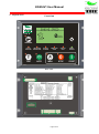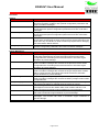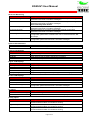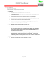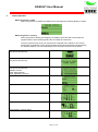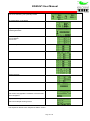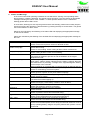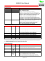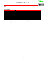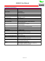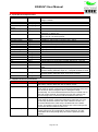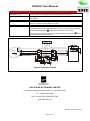
1
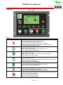
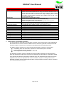
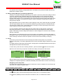
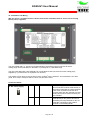
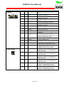
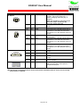
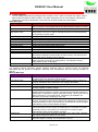
KG934V1 User Manual
KG934V1
Genset Controller
User Manual
KIRLOSKAR OIL ENGINES LIMITED
Laxmanrao Kirloskar Road, Khadki, Pune-411 003, India.
Tel : +91(20) 2581 0341
Fax: +91(20) 2581 3208/ 2581 0209
www.kirloskar.com
The information contained in this document is copyright, and
shall not be reproduced without the written authority of KOEL
©2010
Page 1 of 30
KG934V1 User Manual
KG934V1
Genset Controller
1. Introduction
The KG934V1 is an integrated Engine and AC controller for small gensets. It is a custom unit
specifically designed and manufactured for Kirloskar Oil Engines Ltd.
The unit incorporates both manual and autostart initiated start and stop sequencing, monitors engine
and alternator operating parameters and provides both engine and alternator protection, in a single
integrated package.
The genset operating parameters are shown by scrolling screens on a backlit 128 x 64 dot Graphics
LCD. Alarms and warning are also shown on the LCD and supplemented by an alarm LED and
Hooter output.
The unit provides comprehensive monitoring of the engine and generator operating parameters and
provides automatic shutdown of the genset in the event of damaging conditions. In addition to the
usual engine safety protections the unit monitors coolant level, fuel level, canopy temperature and
generator loading to provide even more comprehensive protection.
In the factory environment, the unit is configured by cloning through a PC system. Field specific
parameters can be adjusted by using the front panel buttons and an inbuilt menu system.
2. Benefits
Reduces system cost:
Integrates engine gauges and AC metering into one unit.
Minimises control panel wiring offering reduced material and labour costs.
Reduces warranty costs by providing comprehensive engine and generator protection and a
maintenance due timer.
Flexible, the unit can be customised by PC cloning with application codes for individual genset
model characteristics and fitments.
Page 2 of 30
KG934V1 User Manual
3. Physical Form
Front View
ALARM
ACK/RESET
LOW OIL
PRESSURE
HIGH ENGINE
TEMPERATURE
T
AUTO
TEST
AUTO
BATTERY
CHARGI NG
UNDER/OVER
SPEED
MAN
Back View
Page 3 of 30
LOW FUEL
LEVEL
GENSET
RUNNING
0
I
STOP
START
KG934V1 User Manual
Functions
System
Function
Protection Shutdown
Manual Start
Manual Stop
Auto Start Stop
Emergency Stop
Engine Monitoring
Function
Over / Under Speed
Lubrication Oil Pressure
Engine Temperature
Battery Voltage
Battery Charging
Radiator Water Level
Fuel Level
Canopy Temperature
Running Hours
Description
Automatic preventative engine and genset shutdown in the event of
abnormal operating conditions with optional configuration parameters and
clear LCD status messages
In response to the front panel pushbutton performs a fully sequenced
engine start with optional configuration parameters and clear LCD status
messages
In response to the front panel pushbutton performs a fully sequenced
engine stop with optional configuration parameters and clear LCD status
messages
In response to a digital input activation the unit performs a fully sequenced
engine start. Deactivating the input performs a fully sequenced engine cool
down then stop. Contactors, if used, are also fully sequenced for changing
the load between Mains and DG..
In response to a digital input performs a fully sequenced engine stop with
optional configuration parameters and clear LCD status messages
Description
Monitors engine speed with optional configuration parameters and clear
LCD status messages this ensures the engine speed remains within
configured limits. Exceeding these limits will result in automatic engine
shutdown to prevent damage.
Monitors engine oil pressure with optional configuration parameters and
clear LCD status messages this ensures the oil pressure remains within
configured limits. Exceeding these limits will result in automatic engine
shutdown to prevent damage.
Monitors engine temperature with optional configuration parameters and
clear LCD status messages this ensures the engine temperature remains
within configured limits. Exceeding these limits will result in automatic
engine shutdown to prevent damage.
Monitors engine battery voltage with optional configuration parameters and
clear LCD status messages this ensures the battery voltage remains within
configured limits.
Monitors engine battery charging status and clear LCD status messages
this ensures the battery is charged when the engine is running.
Monitors engine radiator water minimum level with clear LCD status
messages this ensures the radiator water level remains sufficient. Low
water will result in automatic engine shutdown to prevent damage.
Monitors engine fuel level with clear LCD status messages. Low fuel level
will result in automatic engine shutdown to prevent damage.
Monitors an engine canopy temperature switch with clear LCD status
messages. This function will result in automatic engine shutdown to
prevent damage.
Records engine run hours with clear LCD status messages.
Page 4 of 30
KG934V1 User Manual
Generator Monitoring
Function
AC Phase Voltage
AC Phase Current
AC Phase Frequency
AC Phase Reversal
AC Loading
AC Power Metering
Description
Monitors Genset 1, 2 or 3 phases of AC voltage with optional configuration
parameters and clear LCD status messages.
Monitors Genset 1, 2 or 3 phases of AC current with optional configuration
parameters and clear LCD status messages.
Uses externally fitted 5A CTs.
Monitors Genset phase 1 of AC Frequency with optional configuration
parameters and clear LCD status messages.
Monitors Genset AC for Phase reversal with optional configuration
parameters and clear LCD status messages.
Monitors AC load as a percentage of full load capacity with optional
configuration parameters. Overload units can be selected between KW
and Amps.
Monitors AC power output (KW, KVA, KVAR, PF. KWH) with optional
configuration parameters and clear LCD status messages.
System LED Indications
Function
Alarm
Description
Red LED indication of system alarm.
System LCD Displays
Function
Setup menu
Start Up
Shutdown
Transfer
Description
System configuration menus
Clear step-by-step start up sequencing messages
Clear step-by-step shutdown sequencing messages
Clear step-by-step load transfer messages
Engine LCD Displays
Function
Low oil pressure
High engine temperature
Low coolant level
Low fuel level
Battery Voltage
Description
Engine oil pressure low
Engine temperature high
Radiator water level low
Engine fuel level low
Engine Battery Voltage and Droop voltage at last cranking cycle.
Genset LCD Displays
Function
Phase Voltages
Phase Currents
Phase Frequencies
AC Power Metering
AC Inputs
Function
3 Phase Genset AC Voltage
3 Phase Genset Current
Analog Inputs
Function
Lubrication Oil Pressure
Engine Temperature
Fuel Level
Description
Phase 1, 2 and 3 Voltages Line to Neutral and Line to Line.
Phase 1,2 and 3 Currents
Phase 1
Monitors AC power output (KW, KVA, KVAR, PF. KWH) with optional
configuration parameters and clear LCD status messages.
Description
Genset AC voltages. 0 – 300V AC RMS
Genset AC currents via external 5A CTs. 0 – 5 Amp input
Description
Engine oil pressure sensor. (LOP)
Current limited excitation for resistance sensing
Engine coolant temperature sensor (Air or Water).
Current limited excitation for resistance sensing
Engine fuel level sensor.
Current limited excitation for resistance sensing
Page 5 of 30
KG934V1 User Manual
Analog 1
Digital Inputs
Function
Auto Start / Stop Input
Emergency Stop Input
Oil Switch Input
Canopy Temperature
Digital Input 1
Digital Input 2
Special Inputs
Function
Battery Voltage
Excitation Voltage
Low Water Level / Vbelt
Outputs
Function
Excitation Output
Fuel Output
Crank Output
Output 1
Default = Contactor A
Output 2
Default = Contactor B
Output 3
Default = Preheat
Output 4
Default = Off
Yet to be defined
Current limited excitation for resistance sensing
Description
Auto start switch. Close to Common to activate.
Emergency stop switch. Close to Common to activate
Oil pressure switch (LLOP). Close to Common to activate.
Canopy temperature switch (HCT). Close to Common to activate.
User defined. Default = Not Used. Close to Common to activate.
User defined. Default = Not Used. Close to Common to activate.
Description
Internal measurement of incoming DC supply.
Internal measurement of battery charging alternator excitation voltage.
Oscillating, AC coupled, Zero net current flow. Selectable between Low
Water detection and V Belt broken.
Description
Battery charging alternator excitation control (WL)
Current controlled pulse
Fuel relay coil control.
Open drain 300mA overload protected
Crank relay coil control.
Open drain 300 mA overload protected
ConA
ConB
PreHeat
Start Warn
Fuel Pullin
Crit Alarm
Idle Control
Start Fail
Stop Fail
Low Oil Stop
HiTempStop
Low Fuel Stop
Open drain 300mA overload protected
Page 6 of 30
KG934V1 User Manual
4. Operation
Front Layout
ALARM
ACK/RESET
LOW OIL
PRESSURE
Buttons
Button
0
STOP
MAN
AUTO
AUTO
T
TEST
I
HIGH ENGINE
TEMPERATURE
T
AUTO
TEST
AUTO
BATTERY
CHARGI NG
UNDER/OVER
SPEED
MAN
LOW FUEL
LEVEL
GENSET
RUNNING
0
I
STOP
START
Function Description
Manual Stop button / Menu Control
Used to initiate generator manual stop sequence.
LED blinks during the stopping sequence.
Used to select Off mode, when the engine is in standby.
Used to clear alarms when the Genset was stopped for an alarm.
Used as system menu LEFT button
Manual mode button
Used to select manual mode.
Allows genset to be started only with start button press.
LED indicates manual mode is active.
Auto mode button
Used to select auto mode.
Allows genset to be started only with Auto start input activation.
LED indicates auto mode is active.
Test mode button / Menu Control
Used to select Test mode.
Allows the genset to be started manually without changing the contactors.
LED indicates test mode is active.
Used as system menu DOWN button.
Manual Start button / Menu Control
Used to initiate generator manual start or test sequence.
Used as system menu RIGHT button.
START
ALARM
ACK/RESET
Screen Scroll button / Menu Control
Used to scroll LCD display to next screen.
Used to enter the menu system and accept changes.
Alarm Acknowledge / Menu Control
Used to silence the sounder when the system is in alarm or has an active
warning. Self resetting if enabled.
LED indicates warnings and alarms.
Used as menu system UP button.
Page 7 of 30
KG934V1 User Manual
LEDs
LED
ALARM
LOW OIL
PRESSURE
HIGH ENGINE
TEMPERATURE
BATTERY
CHARGI NG
UNDER/OVER
SPEED
LOW FUEL
LEVEL
GENSET
RUNNING
Function Description
Alarm LED
Indicates warnings and alarm.
Warnings are indicated by 1 blink per second.
Alarms are indicated by 4 blinks per second.
Low oil pressure LED (LOP)
Indicates low oil pressure warnings and alarms
Warnings are indicated by 1 blink per second
Alarm is on solid
High Engine Temperature LED
Indicates warnings and alarm
Warnings are indicated by 1 blink per second
Alarm is on solid
Battery Charging LED
Blinking indicates under voltage, over voltage and charge failure
On solid indicates no excitation while the engine is running
Off indicates battery charging condition is OK
Under / over speed LED
Indicates warnings and alarm
Warnings are indicated by 1 blink per second
Alarm is on solid
Low Fuel Level LED
Indicates warnings and alarm
Warning is indicated by 1 blink per second
Alarm is on solid
Genset Running LED
Indicates the genset is running.
Blinks to indicate the genset is starting or stopping
Initial Power Up
On power up, the unit displays the Kirloskar logo, and turns on LEDs for a lamp test.
The unit then displays the Serial number, Application Code and Firmware version.
After the initialisation process is complete, the unit enters the mode selected in the setup menu and
changes to READY.
Ready
When the unit is in READY all measuring systems and display systems are turned on. The unit
remains on for 1 minute and if the genset is not started in that time the unit goes into sleep mode to
conserve battery power. In this mode the unit wakes periodically to check for any unusual conditions
and if it finds none it goes back to sleep, otherwise it alarms accordingly.
Any activity on the buttons immediately wakes the unit and the appropriate action is taken.
In this state the engine and generator parameters are as expected for a stationary genset. If the
conditions are not as expected, an appropriate warning or alarm is displayed on the LCD.
Mode Selection
The unit may be operated in Auto, Manual, Test or Stop modes. The mode is selected by pressing
the appropriate mode button. The mode is indicated on the LCD and the LED associated with the
mode buttons.
The engine can be stopped with the Stop button in MANUAL, AUTO or TEST modes.
In MANUAL mode the unit responds only to the manual push button and may control A and B
contactors if these options have been enabled.
In the AUTO mode, the unit responds to the autostart input or Remote Starts and controls A and B
contactors.
Page 8 of 30
KG934V1 User Manual
In TEST mode the engine responds only to the manual start button and runs for a preset test time if
configured. Contactors are not controlled.
In STOP mode the unit will enter low power mode, which turns off all LED‟s and sensor checking and
will not start the genset.
To enter STOP mode, press the Manual Stop button when the unit is showing READY in the
manual mode.
To exit STOP mode, press any button.
Manual Mode Operation
To start the genset
When the display is showing READY, press the start button momentarily to start the genset.
Any warning or alarm conditions must be cleared before the genset can be started.
The unit will perform the starting sequence as follows:
PREHEAT.
o The PREHEAT Output , if configured, will activate for the time specified.
FUEL-ON.
o If ETR (Energise To Run) fuel control is configured, the unit will control the fuel output
and display FUEL ON and the proceeds to the CRANK state. If the Fuel Pull-in is
configured it will be on for the first second of this sequence.
o
For ETS (Energise To Stop) the sequence does not activate the output and proceeds to
the Crank sequence after a short delay.
CRANK.
o The Crank output is activated and the display shows „Cranking‟ with a count down time.
o
The Crank output is deactivated when the unit has detected a speed signal above the
crank disconnect speed specified in the settings. If selected, the crank will also terminate
on achieving oil pressure or Battery charging alternator excitation has been achieved.
This provides a secondary crank disconnect function to avoid over-cranking.
o
If the genset does not start, the LCD will show STOPPING, control the Fuel and Crank
outputs accordingly, and return to READY. There are no retries with a Manual Start.
o
If the unit looses power due to battery voltage droop during cranking, and the engine
fires, then on regaining adequate battery voltage, the unit will continue to allow the
engine to run.
RUN UP.
o When the engine starts, the display shows RUN UP with a count down in seconds. This
allows the engine measurement system to stabilise. Over speed and loss of speed
signal are the only parameters checked during RUN UP.
WARM UP
o The display shows WARM UP with a countdown time. This allows the engine to stabilise
at full speed before going on load. Oil pressure and Over-speed are monitored.
RUNNING
o The display shows RUNNING. Operating parameters are scrolled onto the display.
o
Engine temperature alarms have a hold-off period and will not prematurely cause engine
shutdown if the engine has been previously run and has a high temperature.
o
Contactors, if configured, are controlled
Page 9 of 30
KG934V1 User Manual
To stop the genset
Push the stop button briefly.
The unit will perform a stopping sequence as follows:
COOLDOWN
o The display will show COOLDOWN with a count down time.
o
The B contactor (if configured) is opened immediately and after a short delay contactor
A (if selected) is closed.
o
On expiry of the cool down timer the sequence continues to stop the engine.
o
The cool down timer can be set to zero in the menu system to skip this sequence step.
o
To truncate the cool down timer press the stop button again.
o
The set can be returned to the running sequence by pressing the start button. The
contactors return to place the genset on load again.
STOPPING
o The display will show STOPPING with a countdown time.
o
If ETR fuel control has been selected the Fuel output will be deactivated.
o
If ETS fuel control has been selected then the Fuel output will be activated for the Max
Fuel Time or until the engine stops. The stopping process will retry if the engine fails to
stop the first time. Between stopping retries the Fuel output is deactivated for a short
time to help overcome any jamming.
o
The fuel output is controlled until the engine stops rotating and oil pressure decays. If
the Oil Pressure has not decayed by the end of the „Max Fuel Time‟, the fuel output is
deactivated and the controller raises the alarm FAILED TO STOP. The speed must
remain at zero and the oil pressure must be below the alarm set point for the „Stop Time‟
before the engine is considered stopped.
READY
o The engine has stopped and is ready to start again as required.
Page 10 of 30
KG934V1 User Manual
5.
Display Operation
When the genset is ready
When the genset is in standby and waiting for a start signal the following display is shown:
When the genset is running
When the genset is starting and stopping, the display shows the state of the sequence
together with the time remaining before the next state will commence.
Once the genset is fully running or if the genset is stopped and in „READY‟, the running
parameters are displayed. This includes generator and engine parameters simultaneously
on separate displays. The unit sequentially scrolls through screens as shown below:
Splash Screen 1
Only shown at Power up
Splash Screen 2
Only shown at Power up
Product Identification
Only shown at Power up
Software Version
KOEL Serial Number
KOEL Application Code ID
Sequence Status
Engine Speed in RPMs
Oil Pressure
Engine Temperature
Genset Battery Voltage Status
Page 11 of 30
KG934V1 User Manual
Fuel Status (If Enabled)
The Hours remaining can optionally hidden
Oil Temperature (If enabled)
Engine Running Hours
Total Engine Starts
Genset Voltages
Line to Neutral
Line to Line
Genset Amps and Hz
Genset KW and KVA
Genset KVAR and Power Factor
Genset Power Totals
Genset Average
Genset KWHours
Contactor Status
This screen only appears if contactor out control has
been configured.
Any active warnings are shown here.
This is an example warning screen
The sequence returns to the “Sequence Status” screen.
Page 12 of 30
KG934V1 User Manual
6. Alarms and Warnings
In the event of abnormal operating conditions the unit will issue a warning of an impending alarm,
then an alarm if a failure is detected. The genset is then shut down. The LCD shows an appropriate
message indicating the nature of the condition. To draw operator attention to the condition the
flashing general alarm LED is used.
In most cases, Warnings do not stop the genset and are self resetting. Alarms will normally stop the
genset and require the operator to clear the alarm by pressing the Stop or Hooter button. The genset
can not be started if an alarm exists.
Warnings are indicated by slow flashing of the alarm LED and displaying the appropriate message
on the LCD as follows.
Alarms are indicated by fast flashing of the ALARM LED and displaying the appropriate message on
the LCD.
Message
Oil Pressure Low
Engine Temp High
Coolant Temp High
Canopy Temp High
Fuel Level Low
Battery Voltage High
Under Speed
Over Speed
Hirev Alarm
Coolant Level Low
Start Fail
Stop Fail
Belt Broken
Oil-P Fault
Eng-T Fault
Fuel-L Fault
Speed Fault
Function description
The oil pressure went below the alarm setpoint while running.
Check oil level and replenish. Check for blocked oil filter.
The Engine / Coolant temperature went above the alarm setpoint while the
genset was running.
Check for over loading. Check cooling air flows, Check coolant level.
The Canopy Temperature switch input was activated.
Check cooling air flows. Check for overloading.
The Fuel Level is below the alarm setpoint.
The engine is stopped to prevent air and dirt infiltration to the engine.
Replenish the fuel.
The battery voltage went above the setpoint.
High battery voltage usually indicates that the battery charging alternator
has failed and it is producing a voltage which might damage the battery,
control relays or the controller.
Engine shutdown is recommended to minimise the risk of damage and fire.
The engine was running below the under speed setpoint.
Check for overloading. Check fuel system.
The engine was running above the setpoint.
Check governor system. Check power takeoff couplings.
The speed signal indicates the engine is grossly over speed.
Check Governor system.
The radiator water level is below the required level.
The water level needs topping up.
The engine has failed to start.
Check Fuel supply, check battery condition, check air filters.
The engine has failed to stop.
Check stop solenoid, check rack operation.
If the belt break detector has been activated.
Check the belts
The Oil Pressure sensor system is not functioning as expected.
Check oil pressure sensor and associated wiring.
The Engine Temperature Sensor is not functioning as expected.
Check engine temperature sensor and associated wiring.
The Fuel Level Sensor is not functioning as expected.
Check the Fuel Level Sensor and associated wiring.
The Speed Sensing system is not working as expected.
Check the associated speed sensor wiring and external influences such as
poorly operating battery chargers and poorly filtered UPS systems connect
to the load.
Page 13 of 30
KG934V1 User Manual
Message
Speed Detected
Oil Detected
E-S Lock-out
AGF Phase Reversal
AGF Loss GR Volts
AGF Loss GY Volts
AGF Loss GB Volts
AGF Low GR Volts
AGF Low GY Volts
AGF Low GB Volts
AGF High GR Volts
AGF High GY Volts
AGF High GB Volts
AGF High Hz
AGF Low Hz
Function description
Speed signal is unexpectedly present.
Check the associated speed sensor wiring and external influences such as
poorly operating battery chargers and poorly filtered UPS systems
connected to the load. Check electrical safety earthing systems. Check
associated communications networks are isolated and not part of an
unexpected earth loop.
Oil Pressure is unexpectedly present.
Check the Oil Pressure Sensors and associated wiring.
Check the Oil filter system is not blocked.
Check the engine is not running with a failed speed sensing system.
The emergency stop input has been activated. Deactivate the emergency
stop input, then press the stop button to clear this alarm.
The generator has a phase reversal or the wiring is incorrect
Voltage on Generator Red Phase was lost
Voltage on Generator Yellow Phase was lost
Voltage on Generator Blue Phase was lost
Voltage on Generator Red Phase is Low
Voltage on Generator Yellow Phase is Low
Voltage on Generator Blue Phase is Low
Voltage on Generator Red Phase is High
Voltage on Generator Yellow Phase is High
Voltage on Generator Blue Phase is High
Generator frequency is high
Generator frequency is low
7. Load Transfer and Contactor Operation
The unit provides for both Mains and Generator contactor control even though in many applications
this function will not be used, instead an MCB is used to switch the generator to and from the load.
Contactor outputs, if selected, are controlled in both Manual and Auto operating modes.
The Mains contactor output can be setup to deactivate the Mains contactor in several ways
Immediately when the start button is pressed or the autostart input is activated.
A short delay after the start request
When the genset is running and able to take load.
The Generator contactor output will activate only after the Mains contactor has opened and only
when the genset able to take load. The timing is controlled by the XFR DELAY configuration setting.
If the genset was started by activating the Autostart input, then deactivating the input will move the
sequence to the “Run On” sequence then to the “Cool Down” sequence. During cool down the
Generator contactor output is deactivated and after a delay the Mains Contactor output is controlled
to re-activate the Mains contactor.
Page 14 of 30
KG934V1 User Manual
8. Speed Sensing.
The unit can obtain speed information from one of four sources.
Magnetic pickup unit (MPU)
Battery charging flywheel magneto
Generator output 50/60Hz if used for genset control (internally connected from GR)
Battery charging alternator
MPU
The magnetic pickup unit counts teeth on the flywheel and is mounted in the bell housing. It
is important to ensure the gap between the MPU face and the teeth is 1mm to 2mm, as this
distance greatly affects the output of the MPU. The unit requires a minimum of 3VRMS at
low speed to ensure proper crank disconnect. Setup requires calculating the number pulses
per 10 revolutions and the calculated number is then entered into the menu system “Cal
Value”.
Calculate: Number of Teeth x 10 = Speed Pulses Per 10 Revolutions.
Eg: 125 teeth x 10 = 1250.
Enter the number 1250.
Generator
If the unit is used in a genset application the speed source can be the generator 50/60 Hz
output and is connected internally within the unit from the AC input connectors. AC should
NOT be connected directly to the speed MPU / Magneto input. For correct crank disconnect
the generator must be providing a detectable output at low speed and therefore the voltage
at 300 RPM must be greater than 40VRMS. This can be affected by the AVR and must be
confirmed to provide suitable signals and timing for proper crank disconnect.
For setup the number of pulses per 10 revolutions must be calculated and entered into the
menu system “Cal Value”. The generator output frequency and standard RPM must be
known.
Calculate Speed Calibration value as follows:
Cal Value = (Freq x 600) / RPM.
Eg: (50Hz x 600) / 1500 = 20
Enter the number 20.
9. Battery Charging Alternator Excitation
The battery charging alternator excitation system is implemented using a burst mode pulse system.
This ensures reliable self-excitation while managing current consumption during standby, heat
dissipation during fault conditions, and pulsing the battery-charging alternator prior to cranking for
improved speed signal output.
During standby and Ready, the alternator excitation is pulsed once per minute to maintain some
level of residual magnetism in the alternator but still maintaining minimum power consumption. On
receiving a start signal, the unit pulses the alternator excitation input with a burst of 200mA pulses.
The pulse width is dependent on the battery voltage. This pulse burst establishes a definite magnetic
field in the battery-charging alternator prior to cranking. This ensures a significant speed-sensing
signal is generated for crank disconnect sensing. The alternator excitation is turned off and the
engine is cranked without the usual alternator burden loading the cranking process. This aids easier
starting. When the engine has fired and is running, more 200mA pulse bursts are applied. Given the
alternator is rotating at more than the 3000RPM the alternator will achieve self-excitation.
If self-excitation is not achieved this process will repeat for a few seconds before the excitation failed
warning is given.
Alternator excitation may also be used as a secondary crank disconnect signal for the case where
the speed signal has failed immediately the engine starts to run. This feature can be disabled if not
required by setting “Excite Dis” to NO.
Page 15 of 30
KG934V1 User Manual
For systems where a battery-charging alternator is not fitted, turning off the excitation warning will
disable the excitation system.
10. Battery Voltage Monitoring and Charging Detection
A battery is considered charged if (assuming a 12V system. x2 for 24V) its terminal voltage is above
13.1Volts. Typically a fully charged battery has a terminal voltage of 13.6V, above this and the
battery is being overcharged. During cranking the large discharge current will reduce the battery
terminal voltage below 12.5V and the battery cannot increase the terminal voltage again without the
assistance of a charger. This sequence provides a useful mechanism to determine if a battery is
being actively charged.
Many applications have a current meter to show charging current. Such meters provide very limited
value as a good battery will recover its terminal voltage very quickly and then be maintained with a
very low level of trickle current. This trickle current is usually too small a percentage of the current
meters range to provide any useful information.
The unit constantly measures the battery terminal voltage and can detect proper charging and
discharging performance. Voltage readings are taken and compared against an inbuilt voltage
profile. If the battery terminal voltage falls outside the critical voltages for each action then a battery
warning is indicated.
During standby, and particularly where an on line charger is not available, monitoring the health of
the battery is vital. The unit regularly wakes and measures the battery voltage, if it falls below the set
point a warning is issued to ensure the operator is aware of the need for battery recharging.
11. Set-up
In the factory environment the unit can be setup by the KOEL Cloning Utility or by the KOEL
Windows setup utility. In the field, adjustments to the unit can be made using the buttons on the front
panel.
The KOEL Windows setup utility and the KOEL Cloning options are detailed elsewhere and only the
field adjustment method is discussed here.
To enter set-up, when the unit is showing “READY”, press and hold the
button for 20 seconds.
When the unit enters set-up mode the LCD will show “Setup” and request a PIN number.
Column Selection
PIN Entry
Item Selection
Entry to Setup mode can also be done while the unit is “RUNNING” to allow the Genset Amps and
Voltages to be adjusted against the calibration standard (This should ONLY be done in the factory).
Navigating in the setup menu
The setup menu comprises a range of columns where each column comprises of a list of items and
each item has a range of settable values.
Column Headings are as follows:
System
Con A
Start/Stp
AC
Setup
AGF
Setup
Manual
I/O Config Calibration
Comms
Engine
Timers
The
button (UP) is used to select the previous Column, Item, or to Increment a value.
The T button (DOWN) is used to select the next Column, Item, or to Decrement a value.
Page 16 of 30
Stop Alm
Test IP
KG934V1 User Manual
The I button (RIGHT) changes from Column to Item to Value editor.
The 0 button (LEFT) changes from Item to Column and Exit setup mode.
The
button (ENTER) is used to accept Value changes and Start Setup mode.
Setup mode automatically terminates if no button in pressed for 60 seconds, or when you press the
0 button with the column headers list visible.
System Column
Item
Contrast
Disp Update
Disp Hold
PowerUp
Wake Delay
LCDReverse
Site ID
RemoteSetup
Defaults
Engine Column
Item
Crank Rel
Cal Value
U Spd Wrn
U Spd Alm
O Spd Wrn
O Spd Alm
Fuel Select
ETS Tries
Range
0 - 11
2 – 60
sec
5 – 60
sec
Manual
Last
0 – 720
min
No
Yes
Cycle
0 – 30000
No
Yes
No
Yes
Range
100 – 1000
Hz
1 – 2500
OFF
400 – 3600
RPM
OFF
400 – 3600
RPM
OFF
400 – 4000
RPM
OFF
400 – 4000
RPM
ETR
ETS
1-2
Default Description
4
LCD Contrast
3
Display Cycle Time, sets frequency of display updates.
For manual scrolling press the
button for the next
measurement screen.
30
Display hold time. Sets the duration of display hold when the
alarm button is pressed to halt the scrolling
Manual PowerUp mode restore. On power restore places the unit in
either Manual or the last used mode.
0
The interval when the unit will power up and check inputs for
alarms etc. When set to 0, the unit will never enter sleep mode.
Cycle Controls the LCD Pixel Reverse
No = LCD Always shows information with pixels on
Yes = LCD Always shows background with pixels on
Cycle = LCD alternates showing information with pixels on and
showing the background with pixels on
0
Site Identifier. May also be used for asset numbering.
No
Allows the unit to request remote units to enter setup mode
No
Setting to Yes will load all configuration items to their factory
default values.
Note: Engine RPM “Cal Value” calibration will be lost.
Default Description
300
Crank Disconnect Frequency
20
OFF
RPM Calibration Value (Refer to Speed Sensing section)
Warning threshold for slow engine speed
OFF
Alarm threshold for slow engine speed
1600
Warning threshold for high engine speed
1650
Alarm threshold for high engine speed
ETR
Fuel Solenoid Type
ETR (Energize To Run)
ETS (Energize To Stop)
Note: This item is only displayed when Fuel Select = ETS
(See Above)
Maximum Stop Retries for ETS Fuel Control.
2
Page 17 of 30
KG934V1 User Manual
Item
ETS Rest
Range
5 – 60
sec
FuelMaxTm
5 – 600
sec
1 – 600
Off
Litre
50 – 30000
Litre
Off
COF
10 – 180
User
Off
1 – 50
%
Off
5 – 55
%
10 – 180
User
FuelLitreHr
FuelTotal
Fuel Type
Fuel Alarm
Fuel Warn
Oil Type
Oil Range
Oil Alarm
Oil Warn
Oil Prot
10
Bar
0.2 - 3.0
Bar
0.2 – 3.1
Bar
Default Description
Note: This item is only displayed when Fuel Select = ETS
5
(See Above)
Stop Retry Pause time for ETS Fuel Control. During this time the
Fuel output is Off.
15
Maximum fuel solenoid activation time before a Failed to stop
alarm is raised.
4
Genset fuel consumption. Used to calculate the number of
runtime hours remaining for current fuel level.
When set to Off the Hrs is removed from the Fuel Screen.
1000
Total fuel tank volume. Used to calculate the litres of fuel
remaining in fuel tank for current fuel level.
10 –
Fuel level sensor type.
180
User = Curve uploaded by KOEL Setup utility
50
55
10 –
180
10
1.0
1.5
Switch
Sender
Both
Switch
No
Yes
No
Yes
Yes
Oil Dis Dly
Off
On
Off
LowWaterEn
Off
On
On
ETemp Delay
1 – 300
sec
30
ETemp system
Water
Engine
Water
Oil Check
Oil Dis
Yes
Fuel level alarm setpoint.
Alarm output activates and engine is shutdown.
When low fuel alarm is active engine start is inhibited.
Fuel level warning setpoint.
Note: This must be set above the Alarm setpoint.
Selects type of oil sensor being used.
Dual station sensors can be used on same analog input.
User = Curve uploaded by KOEL Setup utility
Used to select the oil sensor full scale in Bar
Low oil pressure alarm shutdown set point.
Alarm output activates and engine is shutdown.
Low oil pressure warning set point and engine continues to
run.
NOTE: This value must be set above the alarm setpoint
Oil protection sensor mode.
Switch = Protection from switch input only
Sender = Protection from analog input only
Both = Combined protection
Checks for oil pressure prior to cranking and raises the
warning „Oil Present‟ if oil pressure is present.
Yes = Uses the digital Oil Pressure input to disconnect the
crank. This may be used as an auxiliary mechanism to
disconnect the crank quickly when the speed source is slow to
establish.
No = Switch is only used for alarm if enabled (Oil Prot)
Oil Pressure Disconnect delay. Used to delay the effect of the
oil disconnect switch by 1 second for cold climatic conditions.
Only configurable via the PC configuration Software.
Enables the Radiator Water Level Alarm. Must be disabled if
the Water level is not monitored.
When the ETemp Type = Engine this becomes the VBelt input
Monitoring Delay time from engine starting before monitoring
for high engine temperature. This is to allow the starting of a
hot engine.
Engine Cooling Temperature Source
Water = Water monitoring
Engine = Engine Air temperature monitoring
Page 18 of 30
KG934V1 User Manual
Item
ETemp Type
70 – 200
ºC
70 – 200
ºC
98
OTemp Type
COF
TS150
User
TS150
OTemp Alarm
70 – 200
ºC
70 – 200
ºC
98
1 – 300
sec
30
OFF
9.5 – 24
Volts
12 – 32
OFF
Volts
12.0 – 38.0
OFF
Volts
OFF
10 – 28
Volts
10.0
Description
Selects Engine temperature sensor type.
COF = Switch: Close on Fault
TS150 = VDO Sensor with FSD of 150ºC
User = Curve uploaded by KOEL Setup utility
High Engine temperature alarm shutdown set point.
Alarm output activates. Engine is shutdown.
High Engine temperature warning set point.
Engine continues to run.
NOTE: This value must be set below the alarm setpoint
Selects Oil temperature sensor type via Analog input 1.
COF = Switch: Close on Fault
TS150 = VDO Sensor with FSD of 150ºC
User = Curve uploaded by KOEL Setup utility
High Oil temperature alarm shutdown set point.
Alarm output activates. Engine is shutdown.
High Oil temperature warning set point.
Engine continues to run.
NOTE: This value must be set below the alarm setpoint
Monitoring Delay time from engine starting before monitoring
for high Oil temperature. This is to allow the starting of a hot
engine.
Low Battery voltage level warning
15.0
High Battery voltage level warning
No
Yes
No
Yes
Yes
Off
On
On
ETemp Alarm
ETemp Warn
OTemp Warn
OTemp Delay
Lo Bat Vlt
Hi Bat Vlt
MaxBat Vlt
Charge Min V
Excite Warn
Excite Dis
Stop on Alarm
Range
COF
TS150
User
Default
TS150
95
95
18.0
13.1
Yes
Maximum Battery Voltage. If the Battery voltage exceeds this
level then the engine is shut down. This is used to protect the
battery from a failed alternator.
The minimum battery voltage below which a “Low Charge
Volts” warning is activated when the engine is running. This
generally indicates an excitation failure or broken alternator
belt.
Yes = charging alternator excitation failure warning enabled.
No = charging alternator excitation failure warning disabled.
Yes = uses successful charging alternator excitation as a
secondary crank disconnect signal to prevent over cranking.
No = Excitation Disconnect function disabled.
On = Engine protection functions are enabled. (Normal setting)
Off = All protection shutdown mechanisms for the engine are
disabled. Warnings and Alarms continue to be indicated.
Off should only be chosen for mission critical applications when
shutdown is not permitted and the engine can run to destruction.
This option is only settable using the KOEL Windows setup
utility.
Timers Column
Item
PreHeat Time
Crank Time
Crank Rest
Range
0 – 60
sec
1 – 30
sec
3 – 50
sec
Default Description
0
Time to turn on the PreHeating output prior to cranking
0 = Skip Preheat delay
10
Maximum cranking time
10
Delay between cranking retries
Page 19 of 30
KG934V1 User Manual
Item
Crank Tries
Range
1 - 10
Run Up
2 – 60
sec
Idle Up
0 – 60
sec
0 – 60
sec
3 – 600
sec
Warm Up
Stop Time
Stop Rest
Test Time
Sounder Time
Maintenance
2 – 20
sec
0 – 720
min
0 – 600
sec
OFF
50 – 1000
hours
Contactor A Column
Item
Range
Unload
Imed Delay
Run
Unload Dly
Xfr Delay
Start/Stop Column
Item
Start Delay
Start Units
StartRestore
Start Warn
3 – 999
sec
0 – 10
sec
Range
0 – 600
Ses
Min
1 – 600
sec
0 – 30
sec
Run On
0 – 3600
sec
Cool Down
0 – 3600
sec
Default Description
3
Crank retries.
Manual and Test start sequencing will not retry.
3
Oil pressure, Temperature, Underspeed, and Overspeed,
checking is disabled to allow these to stabilize during the starting
process. Hirev is active to protect against a jammed governor.
10
Engine Runs at low speed while the Idle Output is activated
Under speed is not monitored
10
Time for the engine to warm up after cranking.
Under speed is not monitored.
15
Time to allow large engines to completely stop rotating and oil
pressure decline when stopping. During this time if Energize to
Stop option is chosen, the fuel solenoid will activate up to the
Fuel Max Time.
6
The time that oil pressure and speed signals are absent for
before the unit considers the engine to be stopped.
0
The duration to run the Engine for when started in Test mode.
0 = Run until the user stops the engine
0
0 = Sounder remains on indefinitely until acknowledged
Value = Sounder maximum time is the value in seconds.
250 Hours between Maintenance Requests
Default
Description
Imed Contactor A unload mode.
Imed = Unloads contactor A at the beginning of the Start Delay
Delay = Unloads contactor A after a delay (see next item) or
when the genset is ready for load, (whichever is the sooner)
Run = Unloads contactor A when the genset is ready for load
Note: Only displayed if Unload is set to Delay
5
Delay for Delayed Unload mode (see above)
5
Delay time between break and make operations for A to B and B
to A contactor transfer control.
Default Description
2
Autostart Delay Time. The time between the detection of an
Autostart activation and the initiation of starting. Start time units
are set in the next item.
SEC Units for the Autostart delay time
Sec = Seconds
Min = Minutes
5
Selects the time for which the Autostart has to be restored
before the start delay timer is reset and starting aborted.
2
Prestart warning time. If an output has been assigned to a Start
Warning function, then it will turn on for this time period before a
start occurs.
60
Run On Time. During run on reactivation of Autostart input will
return the engine to running state. The generator remains on
load.
60
Cool Down Time. Used to cool the turbo and alternator as
required. The generator is off load.
Page 20 of 30
KG934V1 User Manual
Item
Idle Down
AC Setup Column
Item
VPhases
IPhases
CT Ratio
PhaseRev
Range
0 – 360
sec
Range
1–3
1,3
1 – 2000
Off
On
AGF Setup Column
Item
Range
Lo Volt Trip
60 – 240
Volts
Lo Volt Dly
0 – 30
Sec
Hi Volt Trip
110 – 300
Volts
Hi Volt Dly
0 – 30
Sec
Lo Hz Trip
Off
30 – 60
Hz
Lo Hz Dly
0 – 30
sec
Hi Hz Trip
50 – 70
Hz
Hi Hz Dly
0 – 30
Secs
O/Load KW
Off
5 – 6553
KW
O/Load KW Tm
5 – 60
Sec
O/Load Amp
Off
5 – 6553
Amps
O/Load Amp Tm
5 – 60
Sec
LoadImbal
Off
5 – 6553
Amps
LoadImbal Tm
5 – 60
Sec
Manual Column
Item
Transfer
Range
No
Yes
Default
Description
Engine is run and low speed prior to stopping. The Idel output is
on during this time.
Default Description
3
1: = 1 Phase Alternator system.
2: = 2 Phase Alternator system.
3: = 3 Phase Alternator system.
3
Selects the number of CTs used. When the load is balanced
between phases, and cost minimisation is important, a single CT
for phase 1 may be used.
12
Selects the CT ratio
On
Enables genset phase reversal to generate an alarm and shut
down the engine.
Default Description
180
The minimum voltage below which the Genset is shut down
3
275
Time before the alarm will react to Low voltage
The maximum voltage above which the Genset is shut down
3
Time before the alarm will react to high voltage
44
The minimum frequency below which the Genset is shut down.
This is only checked while the engine is Running on load.
3
Time before the alarm will react to low frequency.
56
The maximum frequency above which the Genset is shut down.
3
Time before the alarm will react to high frequency.
30
Maximum KW above which the Genset will shut down
10
Time before the alarm will react to KW Overloading
50
Maximum KW above which the Genset will shut down
10
Time before the alarm will react to Amps Overloading
10
Maximum difference between Amp phases above which will shut
down the engine
10
Time before the alarm will react to Load Imbalances
Default Description
Yes Enables Transfer of the load to the Genset in manual mode.
Page 21 of 30
KG934V1 User Manual
I/O Config Column
Item
Default
O/P1
ConA
O/P2
ConB
O/P3
PreHeat
O/P4
Off
I/P1
I/P2
Description
Selectable Digital Output Function from one of the following:
ConA = Contactor A Control
ConB = Contactor B Control
PreHeat = Control Preheater prior to cranking
Start Warn = Turn on output to warn of an impending start
Fuel Pullin = Controls the high current coil on the Starter motor
Crit Alarm = Turn on output when the is shut down for alarm
Idle Control = Start and stop engine with Idle Output
Start Fail = Turns on when the Engine failed to start
Stop Fail = Turns on when the engine failed to stop
Low Oil Stop = Turns on when the engine stopped for low oil
HiTempStop = Turns on when the engine stopped for Hi ETemp
Low Fuel Stop = Turns on when the engine stopped for low Fuel
Selectable Digital Input Function from one of the following:
Trip = Stop the engine when sensor is activated
Fire Alarm = Stop the engine if fire alarm input is activated
Bypass = prevent engine form starting while activated
Door = Raise a warning while input is activated
Off
Off
Calibration Setup Column
Item
Range
Default
Clear Cal
No
No
Yes
Mains VR Adj
+/-10Vrms
0Vrms
Mains VY Adj
+/-10Vrms
0Vrms
Mains VB Adj
+/-10Vrms
0Vrms
Genset VR Adj
+/-10Vrms
0Vrms
Genset VY Adj
+/-10Vrms
0Vrms
Description
Set this to Yes to reset unit to KG default calibration
Allows KEIL factory to adjust the Main Red phase offset
Allows KEIL factory to adjust the Main Yellow phase offset
Allows KEIL factory to adjust the Main Blue phase offset
Allows KEIL factory to adjust the Genset Red phase offset
Note: The engine needs to be running to adjust this
Allows KEIL factory to adjust the Genset Yellow phase offset
Note: The engine needs to be running to adjust this
Allows KEIL factory to adjust the Genset Blue phase offset
Allows KEIL factory to adjust the Amps Red phase offset
Allows KEIL factory to adjust the Amps Yellow phase offset
Allows KEIL factory to adjust the Amps Blue phase offset
Genset VB Adj
+/-10Vrms
0Vrms
Amps IR Adj
+/-10Vrms
0Vrms
Amps IY Adj
+/-10Vrms
0Vrms
Amps IB Adj
+/-10Vrms
0Vrms
Notes:
1. These items are intended to allow KEIL factory to make adjustments for variations in CTs and external
voltage measuring points.
2. The engine needs to be running to adjust Genset related values.
Comms Setup Column
Item
Range
Comms ID
1 - 240
Baud Rate
1200
57600
Data Bits
7–9
Parity
Even
Odd
None
Stop Bits
1 or 2
UART Mode
None
Modem
LAN
Default
134
9600
8
None
1
None
Description
Comms Address. Required for remote communications
Comms Port Baud Rate
1200, 2400, 4800, 9600, 19200, 38400, 57600
Number of Data Bits
Parity Select
Number of Stop Bits
RS232 Handshaking Mode
None = No RTS/CTS control. 3 wire connection.
Modem = Uses RTS/CTS flow control. 5 wire connection.
LAN = Allows connection to an RS485 adapter. EG: KG18
Page 22 of 30
KG934V1 User Manual
Notes:
1. Unit has basic communications to allow factory testing and validation.
2. Allows the unit to be connected to external KG modules for enhanced communication functions.
Test I/P Column
Item
Range
Description
I Auto Start
Off, Act
Displays the status of the Auto start input for testing
I Emer Stop
Off, Act
Displays the status of the Emergency Stop input for testing
I Oil Switch
Off, Act
Displays the status of the Oil Switch input for testing
I Fire
Off, Act
Displays the status of the Fire Alarm input for testing
I Door
Off, Act
Displays the status of the Door input for testing
I By Pass
Off, Act
Displays the status of the By Pass input for testing
I Trip
Off, Act
Displays the status of the Trip input for testing
I HCT
Off, Act
Displays the status of the HCT input for testing
Stop Alarm Log Viewer Column
This log contains the last 10 reasons that the Engine was stopped
Stop Alarm log history items cannot be deleted or changed except by using the KOEL Windows
setup utility program.
Page 23 of 30
KG934V1 User Manual
12. Unit General Specifications
Feature
Overall Dimensions
Mounting Hole
IP rating
Supply Voltage
Operating Temperature
Storage Temperature
Relative Humidity
Supply Current
AC Voltage Range
AC Frequency Range
CT current range
Overall Accuracy
Digital Output Rating
Digital Input Rating
Analog Input Rating
Input Reference
Displayed Speed Range
Engine Hours
Kilo Watt Hours
Oil Pressure Sensor Type
Oil Pressure Ranges
Engine Temperature Sensor Type
Engine Temperature Ranges
Canopy Temperature Sensor Type
Fuel Level Sensor Type
Battery Volts Measurement
Set-up and Adjustment
Terminations
Testing
Specification
180 x 126 x 51mm
155 x 117mm
IP56 front, IP20 rear
8 V to 36V DC
Nominal Automotive
-20 to +70°C
-20 to +70°C
95% non condensing
Standby
< 10mA
Running
70mA
L-N = 350VRMS.
40 – 70Hz
0 – 5A + 20% Overload
Class 1
Open Drain Relay Coil Driver. 300mA 32VDC max.
Short Circuit protected.
Whetting current 10mA at 12 V DC.
DC input protection for +/- 30V DC
Transient Protected.
Current limited outputs approx 15mA or less as required by sensors/
Short circuit and reverse voltage protected.
DC- / 0V / Common
0 – 4000 RPM
0 – 99999.9 Hours
0 – 999999.9 KWH
Switch: Close on fault
Resistive 10 to 180 Ohms, User Curve
5.0, 7.5, 10 Bar
Switch: Close on fault
Resistive (NTC)
VDO 150ºC, User Curve
Switch: Close on fault
Switch: Close on fault
Resistive: 10 to 180 Ohms, User Curve
8 to 36 Volts
All features may be adjusted using set-up buttons and LCD menu or
via a PC Windows based utility
Amp DUAC / Molex Mini Fit JNR
Environmental Tests: IEC68 Part2
EMC Compliance: EN50081-1, EN50081-2, IEC6100-4-3
Electrical Safety AS 3100 and AS 3260
Page 24 of 30
KG934V1 User Manual
13. Inputs Electrical Specification
Input
Type
Battery + Volts
Power
0V Common
Fuel Level Sensor
Coolant Temperature
Sensor
Canopy Temperature
Oil Pressure Sensor
Power
Analog/Digital
Analog/Digital
Low Water Level
Special
Autostart
Emergency Stop
Oil Pressure Switch
Digital Input 1
Digital Input 2
Excitation
Battery Voltage
GR
GY
GB
GN
CTR
CTY
CTB
CTCom
Digital
Digital
Digital
Digital
Digital
Internal
Internal
Voltage
Voltage
Voltage
Voltage
Amps
Amps
Amps
Amps
SPA
Voltage
SPB
Voltage
SPCom
Voltage
Digital
Analog
Comment
Nominal 12VDC or 24VDC or Station Battery Supply
Range 6-36VDC
0VDC, Common
Suitable for either resistive or switch C.O.F senders
Suitable for either resistive or switch C.O.F. senders
Suitable for switch input. Connect to 0V = Active
Suitable for either resistive or switch senders. Optionally for
protection or display only.
Suitable for probe or switch input.
Open Circuit = No water present
Suitable for switch input. Connect to 0V = Active
Suitable for switch input. Connect to 0V = Active
Used for backup Oil Pressure protection.
Suitable for switch input. Connect to 0V = Active
Suitable for switch input. Connect to 0V = Active
High Impedance input
High Impedance
Generator Red Phase Volts. Max 350VRMS
Generator Yellow Phase Volts. Max 350VRMS
Generator Blue Phase Volts. Max 350VRMS
Generator Neutral
Red Phase CT Amps. (S2) 5A RMS. Max 6A for 1 second
Yellow Phase CT Amps (S2). 5A RMS. Max 6A for 1 second
Blue Phase CT Amps (S2). 5A RMS. Max 6A for 1 second
Common connection for CT S1 terminals. Do not connect to
earth.
Speed A magnetic pickup input 3V – 70V peak at >500 to 10KHz
Speed A Battery Alternator input 2V – 70V peak at 20Hz to 1KHz
Speed B magnetic pickup input 3V – 70V peak at >500 to 0KHz
Speed B Battery Alternator input. Connect to common.
Speed Common 0VDC
14. Outputs Electrical Specification
Output
Type
Comment
Charger WL
Current
200mA burst mode pulsed current controlled output. Used to provide
the battery charging alternator with excitation current.
Stop / Fuel Relay
Open Drain 300mA Open Drain protected coil drive. Max 36VDC
This output is used to control the fuel solenoid interposing relay and
can be set for either Energise to Run or Energise to Stop
functionality. It is recommended that the fuel relay is located near to
the fuel control solenoid. This position removes the need for high
current wiring to the control box and thus leads to lower cost.
Crank Relay
Open Drain 300mA Open Drain protected coil drive. Max 36VDC
This output is used to control the interposing crank relay coil. The
crank relay should be sized for the crank contactor current. It is
recommended that the crank relay is located near to the starter
motor. This position removes the need for high current wiring to the
control box and thus leads to lower cost.
Output 1 to Output 4
Open Drain 300mA Open Drain protected coil drive. Max 36VDC
These outputs can be configured for various functions. The are
intended to drive interposing relays and not the particular loads
directly.
Page 25 of 30
KG934V1 User Manual
15. Installation and Wiring
NB: The unit is a complex electronic device and caution should be taken to ensure correct wiring
before power is applied.
The unit is fitted with 2, 3, 6 and 14 way Molex Minifit or equivalent socket connectors for which
mating plugs can be selected from the Molex, Tyco/Amp PE, or TPK 5566 range.
The unit is also fitted with 4 way Mate-N-Lok or equivalent socket connectors for which mating plugs
supplied by Tyco Electronics or equivalent can be used.
2
The majority of unit wiring is low current for which 0.75mm wire is sufficient. This excludes the CT wires
2
(CTR, CTY, CTB, CTCom) for which 1.5mm wire should be used.
Connector Details
Connector Assignment
J1: DC Power Supply
Pin
J1-1
Wire
01
Name
DC -
J1-2
02
DC +
J1 DC
1
2
Function
Battery – Supply. 0V, Common.
This connection must be made directly to
the engine crankcase for lowest electrical
noise. This connection must not have
currents other than the controller currents
flowing and must be used exclusively for
the controller.
Battery + Supply. This connection must be
made directly to the positive terminal of
the battery for best performance. Do not
make this connection to the positive
terminal on the Starting Motor.
Page 26 of 30
KG934V1 User Manual
Connector Assignment
J2: Engine
J2 Engine
9 11 13
3
5
7
2 4
6
8 10 12 14
1
J3: Input / Output
Pin
J2-1
Wire
05
Name
Charger WL
J2-2
06
Stop/Fuel Relay
J2-3
03
Crank Relay
J2-4
19
Fault Relay
J2-5
15
HCT Switch
J2-6
08
Oil Switch
J2-7
10
LOP Sensor
J2-8
09
J2-9
12
Engine Temp
Sensor
Fuel Lev Sensor
J2-10
11
Wat Lev Sw
V Belt
J2-11
14
J2-12
13
J2-13
16
Auto Start
Switch
Emergency Stop
Sw
Analog Input 1
J2-14
NC
No Connection
J3-1
20
Output 1
J3-2
21
Output 2
J3-3
22
Output 3
J3-4
23
Output 4
J3-5
17
Digital Input 1
J3-6
18
Digital Input 2
J3 I/O
1
3
5
2 4
6
Function
Battery Charging Alternator Excitation. WL
point
Coil Drive for the Fuel Control Relay.
Switches to common
Coil Drive for the Crank Relay.
Switches to common
Coil Drive for the Fault Relay.
Switches to common
High Canopy Temperature Switch Input.
Activate by switching to common
Low Oil Pressure Switch Input. Activate by
switching to common
Lube Oil Pressure measuring input.
Measures Resistance.
Engine Temperature measuring Input.
Measures Resistance.
Fuel Level sensor Input. Measures
Resistance.
Water Level or V Belt sensing Input.
Oscillating Output/Input system.
Connects to water level probe, water level
switch or V Belt broken switch
Auto Start Input. Activate by switching to
common. Starts the DG
Emergency Stop Switch. Activate by
switching to common. Stops the DG
Analog Input 1. Measures Resistance.
Used for the Oil Temperature Sensor.
Analog Input 2. Measures Resistance. No
hardware fitted and No Functions
assigned to this input at this time.
Coil Drive for an external control Relay.
Switches to common. Configurable for
various functions
Coil Drive for an external control Relay.
Switches to common. Configurable for
various functions
Coil Drive for an external control Relay.
Switches to common. Configurable for
various functions
Coil Drive for an external control Relay.
Switches to common. Configurable for
various functions
Digital Input 1. Activate by switching to
common. Configurable for various
functions. See Menu Options above.
Digital Input 2. Activate by switching to
common. Configurable for various
functions. See Menu Options above.
Page 27 of 30
KG934V1 User Manual
Connector Assignment
J4: Speed
Pin
J4-1
Wire
24
Name
Speed A
J4 Speed
3
2
1
Function
Frequency sensing Input for speed
sensors. Connects to MPU (MPU +),
Battery Charging Alternator (W), or
Magneto.
Note: Not suitable for connecting to the
Generator Output. Instead Use the
Generator Voltage Input GR
J5 Current Transformers
J4-2
25
Speed B
J4-3
J5-1
26
31
Shield
CTR
J5-2
34
CT Com
J5-3
32
CTY
J5-4
33
CTB
J6-1
27
GR
J6-2
28
GY
J6-3
29
GB
J6-4
30
GN
J5 CTs
1
3
2
4
J6: Alternator AC Input
J6 Generator
27
28
J7: Test Port
29
30
J7
Test Port
Return connection for the MPU. Connect
to (MPU -)
Common connection for the MPU shield.
Connects to the external Red Phase CT
terminal S2. The load wire must pass
through the CT in the direction of the CT
arrow.
Connects to the external CT‟s commoned
S1 terminals.
Connects to the external Yellow Phase CT
terminal S2. The load wire must pass
through the CT in the direction of the CT
arrow.
Connects to the external Blue Phase CT
terminal S2. The load wire must pass
through the CT in the direction of the CT
arrow.
Connects to the Generator Red Phase
output.
Connects to the Generator Yellow Phase
output
Connects to the Generator Blue Phase
output
Connects to the Generator Neutral output,
where available.
Programming / Validation / Test Port.
NB: Connect ONLY KG expansion
modules to this port.
NB: The unit is a complex electronic device and caution should be taken to ensure correct wiring
before power is applied.
Page 28 of 30
KG934V1 User Manual
16. Trouble shooting
The unit displays the following messages when an alarm occurs. Alarms shut down the engine, set the
alarm output and flash the alarm indicator. The alarm indications can be cleared after the genset has
stopped, by pressing the stop button. The hooter can be silenced with the Hooter Button.
Alarm Messages
Message
Cause
Low Oil Pressure
Oil pressure has not reached the Oil Alarm set point (Oil Alarm) at the end of
the run up time or has dropped below this value when the engine is running.
Low Fuel Level
Fuel level is less than the minimum value set point.
High Engine Temp
Engine temperature has exceeded the high temperature set point. The
High Water Temp
temperature icon turns on. Either message may also be shown depending
on temperature system setup.
High Canopy Temp
Canopy temperature switch was activated.
Low Water Level
Water Level has gone below the water sensor.
Under speed
Engine speed has dropped below the under speed set point.
Over speed
Engine speed has exceeded over speed set point.
High Rev
Engine has exceeded safe operating speed.
No Speed Signal
Engine has lost speed signals while running.
Start Failure
The engine has failed to start.
Stop Failure
The engine has failed to stop.
E-S Lock out
The emergency stop input has stopped the engine.
Oil Pressure Flt
The unit has detected that the Oil Pressure sender has become open circuit.
Normally this indicates a faulty sender or broken wiring. This will only shut
down when the Oil System is set to Sender.
Engine Temp Flt
The unit has detected engine temperature has not risen above 50 degrees
after 5 minutes of running or the temperature. This indicates a faulty
temperature sender or damaged.
Oil Temp Flt
The sensor connected to Analog 1 input is faulty or open circuit.
The following warning messages indicate potential problems. When a warning occurs, the message
associated with the warning is displayed. Warnings clear automatically when the warning condition is
cleared.
Warning Messages
Cause
Message
No Excitation
Excitation voltage is low when engine is running. This indicates a probable
charging fault or the alternator belt has broken.
Low Charge Volts
Battery Voltage is below the charging voltage setpoint when the engine is
running. Indicates that the alternator is not charging the battery.
Under Voltage
Battery Voltage is below the low battery setpoint.
Over Voltage
Battery Voltage is above the high battery volts setpoint. This may be due to
a faulty regulator or battery charger.
Oil Lock Out
The unit has detected that the oil pressure is above the oil pressure alarm
setpoint with the engine not running. This warning prevents the engine from
attempting to crank with the engine potentially running. This may be due to a
faulty oil sender or a very tight engine. This warning is disabled if Oil
Pressure Check before Cranking is set to Off.
Tacho Lock Out
The unit has detected that a speed signal is present with the engine not
running. This warning prevents the engine from attempting to crank with the
engine potentially running. This warning can sometimes be caused by ripple
generated by mains powered battery chargers.
Excite Lock Out
The unit has detected that Excitation is present with the engine not running.
This warning prevents the engine from attempting to crank with the engine
potentially running. This warning can sometimes be caused by ripple
generated by mains powered battery chargers.
AutoStart On
The unit has detected an Autostart signal when not in auto mode, indicating
the engine needs to be started in Auto mode.
Low Oil Pressure
The Oil Pressure has dropped below the Oil Pressure Warning set point
while the engine is running. The Oil Pressure Icon is lit.
Page 29 of 30
KG934V1 User Manual
No Speed Signal
Maintenance
pressing and holding the
button for 30 seconds. If the engine
maintenance is carried out prior to the timer expiring, pressing the
for 60 seconds will reset the timer.
button
Con A
Low Fuel Level
Fuel Level Flt
Engine Coolant temperature has exceeded the high temperature warning
set point after the Temperature monitoring delay has expired.
Canopy Temperature was activated after the Temperature monitoring delay
has expired.
Fuel level is less than the warning set point.
The unit has detected that the fuel sender is open circuit. This is only a
warning, and will not shut down the engine
A speed signal could not be detected after the engine had started
The time since the last maintenance has exceeded the maintenance time.
The alarm output is not activated for this warning. The warning is cleared by
Con B
High Engine Temp
High Water Temp
High Canopy Temp
Typical Contactor Control
KIRLOSKAR OIL ENGINES LIMITED
Laxmanrao Kirloskar Road, Khadki, Pune-411 003, India.
Tel : +91(20) 2581 0341
Fax: +91(20) 2581 3208/ 2581 0209
www.kirloskar.com
Part No. 2H.831.04.0.00
Page 30 of 30