1
ECRM RIP for
Windows NT
™
0
Operator Guide
Eclipse Release
™
November 2002
AG12325 Rev. 5
Copyright and Trademarks
Eclipse Release
November 2002
Part number: HK–6.0–OEMN–ECLIPSE
Copyright © 1992–2002 Global Graphics Software Limited.
All Rights Reserved. No part of this publication may be reproduced, stored in a retrieval system, or transmitted, in any form or by any means, electronic, mechanical, photocopying, recording, or otherwise, without the
prior written permission of Global Graphics Software Limited.
The information in this publication is provided for information only and is subject to change without notice.
Global Graphics Software Limited and its affiliates assume no responsibility or liability for any loss or damage that may arise from the use of any information in this publication. The software described in this book is
furnished under license and may only be used or copied in accordance with the terms of that license.
ECRM is a registered trademark of ECRM, Incorporated. ScriptWorks is a registered trademark and Harlequin, the Global Graphics Software logo, Harlequin RIP, ColorPro, EasyTrap, FireWorks, FlatOut, Harlequin
Color Management System, HCMS, Harlequin Color Production Solutions, HCPS, Harlequin Color Proofing,
HCP, Harlequin Error Diffusion Screening plugins 1 bit and 2 bit, HEDS1 and HEDS2, Harlequin Full Color
System, HFCS, Harlequin ICC Profile Processor, HIPP, Harlequin Standard Color System, HSCS, Harlequin
Chain Screening, HCS, Harlequin Dispersed Screening, HDS, Harlequin Micro Screening, HMS, Harlequin
Precision Screening, HPS, HQcrypt, Harlequin Screening Library, HSL, Harpoon, RipFlow, ScriptWorks
MicroRIP, ScriptProof, ProofReady, Scalable Open Architecture RIP, SOAR, SetGold, SetGoldPro, TrapMaster,
TrapPro, TrapProLite, TrapWorks, PDF Creator and RIPFlow are all trademarks of Global Graphics Software
Limited.
Portions licensed under U.S. Patents: Nos. 4,500,919, 4,941,038 and 5,212,546. EasyTrap is licensed under one
or more of the following U.S. Patents: Nos. 5,113,249, 5,323,248, 5,420,702, 5,481,379.
Adobe, Adobe Photoshop, Adobe Type Manager, Acrobat, Display PostScript, Adobe Illustrator, PostScript,
Distiller and PostScript 3 are either registered trademarks or trademarks of Adobe Systems Incorporated in
the United States and/or other countries which may be registered in certain jurisdictions.
Global Graphics Software Limited is a licensee of Pantone, Inc. PANTONE Colors generated by the
Harlequin RIP are four-color process simulations and may not match PANTONE-identified solid color standards. Consult current PANTONE Color Publications for accurate color. PANTONE , Hexachrome , and
PANTONE CALIBRATED™ are trademarks of Pantone, Inc. © Pantone, Inc., 1991.
®
®
®
Other brand or product names are the registered trademarks or trademarks of their respective holders.
US Government Use
The ScriptWorks software is a computer software program developed at private expense and is subject to the following Restricted Rights
Legend: “Use, duplication, or disclosure by the United States Government is subject to restrictions as set forth in (i) FAR 52.227–14 Alt III or
(ii) FAR 52.227-19, as applicable. Use by agencies of the Department of Defense (DOD) is subject to Global Graphics Software’s customary
commercial license as contained in the accompanying license agreement, in accordance with DFAR 227.7202-1(a). For purposes of the FAR,
the Software shall be deemed to be `unpublished’ and licensed with disclosure prohibitions, rights reserved under the copyright laws of the
United States. Global Graphics Software Incorporated, 95 Sawyer Road, Waltham, Massachusetts 02453.”
ii
AG12325 Rev. 5
Table of Contents
Preface ............................................................xv
Introduction to the Harlequin RIP ...................1
1.1
1.2
1.3
What is the Harlequin RIP? 1
Input and output formats 2
Versions of the Harlequin RIP 2
Why use the Harlequin RIP? 3
The Harlequin RIP in depth 4
Software RIPs compared to hardware RIPs 5
File format and version support 6
Extended color capabilities 8
Color, screening, and Roam functionality 11
Memory management 12
Headless RIP Option 14
FlatOut 14
Screening options 15
Harlequin ColorPro“
16
Graphics formats 17
Input and output methods 18
Complex jobs 20
Throughput control 20
Previewing 22
Page buffer compression 22
Fonts and font handling 23
Convenience features 24
Running the Harlequin RIP ...........................27
2.1
AG12325 Rev. 5
Machine requirements
Performance 28
28
ECRM RIP Operator Guide
iii
Ability to RIP a job 30
Driving a printer effectively
2.2
2.3
2.4
2.5
2.6
32
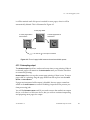
Installing printer interface cards 33
Harlequin RIP folder structure 34
Starting up the Harlequin RIP. 39
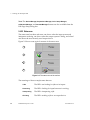
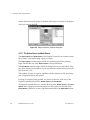
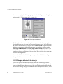
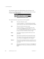
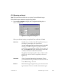
The menus 40
The tool bar 41
Menus affected by optional features 45
ColorPro“ menus
45
TrapPro“ and TrapProLite“
46
Media Saving 47
Stopping the Harlequin RIP 47
Quitting the Harlequin RIP 47
Stopping the computer 48
Getting Started with the Harlequin RIP ....... 49
3.1
3.2
3.3
3.4
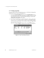
A simple Harlequin RIP session 49
Creating a page setup 50
Creating a simple job 53
Previewing the image on screen 55
Outputting to a real device 57
Sending a job to the Harlequin RIP 60
A more complex use of the Harlequin RIP 62
Saving a page setup 62
Associating a page setup with an input 64
Using the Harlequin RIP with a spool folder 64
Monitoring the Harlequin RIP 66
Harlequin RIP Output Methods .................... 69
4.1
4.2
4.3
iv
Historical overview 69
Page buffering modes 70
Operating modes 71
The throughput system 73
Output Controller 73
Job management 80
Page buffers produced by older versions of the Harlequin RIP
ECRM RIP Operator Guide
AG12325 Rev. 5
87
4.4
4.5
Advanced details of page buffering modes 88
Multiple (Parallel) mode 88
Multiple mode 89
Single mode 90
Single (if required) mode 91
Multiple (Parallel) compared to Single (if required) mode 92
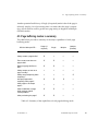
Page buffering modes: a summary 93
Configuring Output Formats .........................95
5.1
5.2
5.3
5.4
5.5
5.6
5.7
5.8
5.9
5.10
5.11
AG12325 Rev. 5
Creating and managing page setups 95
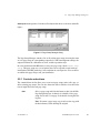
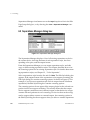
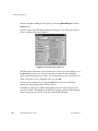
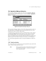
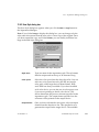
Page Setup Manager dialog box 96
Controls and actions 97
Reordering page setups 98
Selecting several page setups 98
Closing the Page Setup Manager 99
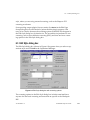
Edit Page Setup dialog box 99
Closing the Edit Page Setup dialog box 101
Closing the New Page Setup dialog box 101
Selecting different devices 102
Setting the resolution 103
Image interpolation 104
Sending output to the screen 107
Using the Preview device 107
Using the None device 108
Roam and Preview windows 109
Output to Preview 112
Output to None 112
Output to TIFF 113
TIFF file location and naming options 114
TIFF file format options 116
TIFF file post processing 117
Sending output to a printer 121
ProofReady plugins 122
Using ProofReady plugins 123
Multiple device output plugins 124
ECRM RIP Operator Guide
v
Installing and using multiple device plugins
5.12
5.13
5.14
5.15
5.16
5.17
5.18
5.19
5.20
5.21
5.22
5.23
5.24
5.25
vi
125
Output plugin dialog boxes 128
Separations, Screening and Color 128
Media saving option 129
The Media Saving dialog box 131
Media Saving dialog box example 136
Media and time saving using optimization 137
Other options that save media 137
Default page size 138
Margins 138
Printing effects 140
Scaling the image 141
Features 141
Using features 141
Adding other features 144
Cassette management 144
Page Setup Options 145
PostScript Language compatibility level 145
Run prep at start of job 146
Remove color operators 146
Fast patterns 147
Emulate old imagemask behavior 147
Add showpage at end of job if necessary 147
Abort if calibration on, and the selected cal set does not match
job 148
Abort the job if any fonts are missing 148
Preserve monochrome and preseparated jobs 148
Number of copies to print 149
Page Setup Option Extras 149
Adobe Photoshop features 150
Adobe Illustrator features 151
QuarkXPress features 153
Macromedia FreeHand features 154
PDF Options 155
Calibration 155
Device calibration 155
ECRM RIP Operator Guide
AG12325 Rev. 5
Press calibration 156
Use of a different printing press
Tone curves 157
5.26
Other page setup options
156
157
Screening ......................................................159
6.1
6.2
6.3
6.4
6.5
6.6
6.7
6.8
6.9
6.10
AG12325 Rev. 5
Managing separations styles 159
Separations Manager dialog box 160
Edit Style dialog box 161
Halftoning 162
Dots, halftone cells, and screens 163
Dot shape 165
Spot function screens 166
Threshold screens 166
Halftone options 167
Dot gain 168
Suggested background reading 168
Screen angles 169
Changing angles for separations 170
Dot shapes 171
Common dot shapes 172
Other dot shapes 174
Halftone frequency 175
Changing the halftone frequencies 176
Screening options and number of gray levels 176
How many gray levels can you see? 176
How many gray levels do you get? 177
How many gray levels do you need? 178
Gray level controls 180
Job settings and Harlequin RIP settings 181
Harlequin Precision Screening 183
Controlling extra grays in HPS 183
Using the HPS controls 184
Possible problems with output 188
HPS and pattern screens 190
Increasing HPS performance 190
ECRM RIP Operator Guide
vii
6.11
6.12
6.13
Harlequin Screening Library 192
Switching on HSL 192
Selecting an HSL screen set 193
Harlequin Chain Screening (HCS) 193
Harlequin Dispersed Screening (HDS) 194
Harlequin Micro Screening (HMS) 199
Troubleshooting HSL 200
Automatic detection of color separations 201
Using Harlequin Harpoon PCI 201
Configuring the RIP ..................................... 203
7.1
7.2
7.3
7.4
7.5
7.6
7.7
7.8
7.9
7.10
7.11
7.12
7.13
7.14
viii
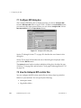
Configure RIP dialog box 204
How the Harlequin RIP controls files 204
Workspace folder 205
Page buffer folder 205
Control of page buffering modes 206
How to choose the page buffering mode 206
Using a printer that can stop / start 206
Compressing page buffers 208
Band size for printing buffer 208
Minimum compression ratio 209
Job timeout 209
Threads and parallel processing 210
Network buffer size 210
Increasing throughput 210
Freeing the sending application 210
Printer buffer size 211
Extras 212
Specifying prep files 214
Automatic prep loading 214
Startup prep 214
Harlequin RIP memory allocation 214
Minimum free disk space 216
Disable sounds 216
Resetting the Harlequin RIP to default values
Choosing the user interface language 217
ECRM RIP Operator Guide
216
AG12325 Rev. 5
Requirements and limitations
Procedure 218
217
Configuring Input .........................................221
8.1
8.2
8.3
8.4
8.5
8.6
8.7
8.8
AG12325 Rev. 5
Input management 222
Managing input plugins 224
Turning on the input system 226
Adding a new input source to the list 226
Copying an input plugin 227
Editing the details for an input source 228
Configuring an input plugin 228
Deleting an input source 228
Enabling and disabling input sources 228
Using the AppleTalk input plugin 229
Configuring an AppleTalk input source 229
Using the NT Print input 230
Installing the plugin 230
Configuring an NT Print input 231
Creating a printer under Windows NT 232
Using the printer from Windows NT 234
Printing from a DOS command prompt 234
Troubleshooting NT Print 235
Using the NT Pipe input 236
Installing the plugin 236
Creating an NT Pipe input 237
Configuring the named pipe 237
Connecting an application to the Harlequin RIP 239
Using the Spool Folder input folder 240
Configuring a Spool Folder input source 241
Using the Socket input plugin 245
Requirements 247
Configuration preliminaries 247
Configuring a Socket input plugin 250
Using the Asynchronous Socket plugin 253
Creating an asynchronous socket input 253
Sample job 254
ECRM RIP Operator Guide
ix
8.9
8.10
8.11
8.12
8.13
8.14
8.15
8.16
8.17
8.18
8.19
8.20
Using the Asynchronous Socket Quit plugin 254
Using the Serial input plugin 255
Overview 255
Establishing a serial link 256
Configuring a Serial input plugin 257
ASCII and binary modes 259
Using more than one method 261
Using the Print File command 262
Printing several files 263
Printing PostScript-language files 263
Printing PDF files 264
Printing PDF version 1.4 265
Working with transparency 265
AcroForms 267
Related documentation 269
PDF Options dialog box 269
Usage 274
Limitations and special treatment 275
Printing JPEG and JFIF files 276
Limitations 276
Printing GIF files 277
Printing TIFF/IT files 277
General 277
Installation and requirements 279
Usage 280
Printing TIFF 6.0 files 282
Procedures 282
Limitations and extensions 283
Printing page buffer files 284
Requirements and preparation 285
Printing procedure 286
Entering PostScript-language code by hand 287
Media Management ..................................... 289
9.1
x
Why manage your media? 289
Overview of the Harlequin RIP capabilities 290
ECRM RIP Operator Guide
AG12325 Rev. 5
Suitable devices 291
What you need to do 292
9.2
9.3
9.4
Advancing and cutting media interactively 292
Device menu 293
Using the Device menu 293
Advancing and cutting media automatically 294
Automatic use 295
Enabling and disabling media management 297
Cutting media 297
Feeding media 298
Interaction with other Harlequin RIP options 300
Monitoring media 300
Setting up the monitoring system 300
Cassette Manager and Edit Cassette dialog box 301
Using media management 305
Using media management with multiple setups 305
Low media warnings 306
Hardware feeds 306
Online developers or processors 308
Monitoring your media 309
Fonts .............................................................311
10.1
10.2
10.3
10.4
Supplied fonts 312
Types of font 312
The DLD1 format 313
Installing fonts in the Harlequin RIP 314
Install Fonts command 316
Downloading fonts to the RIP 317
10.5 Pre-loading fonts 318
10.6 Producing a list of installed fonts 319
10.7 Proofing fonts 319
10.8 Removing fonts 321
10.9 Composite fonts 322
10.10 Font substitution 323
Calibration ....................................................325
AG12325 Rev. 5
ECRM RIP Operator Guide
xi
11.1
11.2
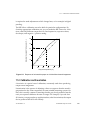
Why calibration is needed 325
Calibration and linearization 327
Non-linear devices 328
11.3 Calibration in the Harlequin RIP 329
Accessing calibration functions 330
Calibration sets 330
11.4 Example procedure 330
Devices and requirements 330
Choosing the correct exposure 333
Creating a calibration set 337
Entering the data 339
Applying the calibration 341
11.5 Editing calibration sets 342
Establishing a workflow 342
Variations on the Edit Calibration dialog box 344
Choosing and labeling calibration sets 345
Saving calibration sets 346
11.6 Consistency of calibration 346
Checking calibration 346
Assessing attainable accuracy 347
11.7 Tone curves 348
Creating and using tone curves 349
11.8 Press calibration 349
How does press calibration work? 350
Alternative uses of press calibration 352
Direct to press 353
Version history: Linear and None 353
11.9 Using a combination of calibration sets 354
11.10 Print Calibration dialog box 355
Buttons 355
Other controls 356
11.11 Calibration Manager dialog box 357
List headings and entries 359
Buttons 362
11.12 Edit Calibration dialog box 363
Entry methods and variations 364
xii
ECRM RIP Operator Guide
AG12325 Rev. 5
Checks in the Edit Calibration dialog box 365
Warning Criteria panel 365
Other controls 366
Values 369
Test strips and data boxes for patches 369
Controls 369
Exiting the Edit Calibration dialog box 373
Color Separation ..........................................375
12.1
12.2
12.3
12.4
12.5
12.6
12.7
12.8
AG12325 Rev. 5
Introduction 376
Alternative process color systems 377
Spot colors 378
Types of color jobs 379
Harlequin RIP 379
Harlequin ColorPro 380
What color separations are 380
Knockouts and overprinting 381
Producing color images from separations 384
How color separations are produced 386
Color PostScript-language jobs 387
Preseparated jobs 387
Creating and managing separations 388
Separations Manager dialog box 389
Controls and actions 389
New Style dialog box 391
Selecting several separations styles 392
Closing the Separations Manager 392
Edit Style dialog box 393
Producing separations 395
Other options 398
Recombination 399
Recombination and composite jobs 401
Closing the Edit Style dialog box 401
Color Setup 401
Define color setups (no color management) 402
Overprinting controls 409
ECRM RIP Operator Guide
xiii
Black generation and undercolor removal
Black generation 410
Ink densities 413
409
12.9 Color separation angles in job 413
12.10 Trapping features 414
Trapping and QuarkXPress 414
Controls in the Harlequin RIP 415
12.11 Pages in the Output Controller 415
Roaming separations 416
Roaming composite pages 416
Changing the color in Roam 417
xiv
Appendix A
Troubleshooting
419
Appendix B
Jobs Containing Color Management Data
441
Appendix C
Using Genlin
445
Appendix D
Harpoon PCI Screening Accelerator
453
ECRM RIP Operator Guide
AG12325 Rev. 5
Preface
This manual is a complete guide to using the ECRM RIP on PC platforms running Microsoft Windows NT , Windows 2000 and Windows XP.
®
The ECRM RIP is a PostScript' language interpreter and rasterizer. It supports the full range of PostScript 3 operators, as well as earlier versions of the
language. It is also a complete RIP Management System that can process a
wide variety of file formats including PDF, EPS and TIFF.
The ECRM RIP is based on proven Harlequin RIP technology and incorporates
a Harlequin RIP. The guide covers the features of the RIP in a structured way,
giving examples that show you how to perform a wide variety of useful tasks in
the RIP. For more details about the other versions of RIPs available, see Chapter 1, “Introduction to the Harlequin RIP”.
Contents of this manual
This manual discusses basic concepts at an early stage, leaving more complex
issues for the later chapters. In addition, each chapter starts with a basic
description of the relevant features before describing in detail the more technical issues involved.
Changes to the Eclipse Release of the RIP include:
•
Harlequin ColorPro™ with new enhanced user interface.
•
Support for N-color and Gray Profile ICC profiles.
AG12325 Rev. 5
ECRM RIP Operator Guide
xv
•
Press/Proof simulation added to color products (RGB proofing
workflow).
•
Black threshold parameter added to custom rendering intent GUI.
•
ProofReady Plugin support on Mac OS X.
•
Harlequin 1 bit and 2 bit EDS plugins.
•
SetGold™ v1.2 and SetGoldPro™ on Win NT only.
•
TrapPro™ trapping.
•
Trap Zone support for PDF files.
•
PDF/X-1a and PDF/X-3:2002 support.
•
PDF 1.4 including: transparency, JBIG2, 128 bit encryption, output
intents, and referenced PDF. Because of this, the InFlight checker has
been removed.
•
Support for Palette color (Index color) TIFF files.
Items which have been relocated in this version include:
•
The Color Options button is removed from the Page Setup dialog box
and is replaced by a Color Setup Manager and Color Setup dialog box.
•
Trapping controls appear in the Trapping section of the Edit Page Setup
dialog box.
•
Ink set options have been removed from the Edit Separations dialog and
placed within their own Ink Set Manager. See the TrapPro User Manual for
more information.
•
Honor Color Management (PDF and PS) options were previously in the
Page Setup > PDF Options dialog and Page Setup Options > Extras dialog.
The option is now called Override color management in job and is available in the Color Setup dialog.
Changes to v5.5r1a include:
xvi
•
The addition of a Mac OS X version of the manual.
•
A small number of corrections, deletions and additions, all highlighted
by change bars.
ECRM RIP Operator Guide
AG12325 Rev. 5
Changes to v5.5r1 include:
•
AcroForms support, see Section 8.14.3 on page 273.
•
Convert RGB blacks to true black, see “Output Controls for RGB
options in the New Color Setup dialog box” on page 395.
•
The way calibration works has been changed. For more information see
“Entering the data” on page 327.
The following changes were made for v5.5.
•
Image Interpolation support, see Section 5.4.2 on page 112.
•
Media Saving feature, see Section 5.14 on page 138.
•
PDF 1.4 InFlight checker.
Less significant changes include:
•
Automatic creation of Font resources for installed CID fonts, see
Section 10.2 on page 300.
•
Font substitution changes, see Section 10.10 on page 311.
•
Change to the messages when calibrating, see Section 11.4.2.2 on
page 323.
•
Changes to the PANTONE MATCHING SYSTEM, see Section 12.1.2.1
on page 364.
®
The first three chapters contain information about what the Harlequin RIP
does, and how to get it up and running on your machine.
Chapter 1, “Introduction to the Harlequin RIP”, gives a description of
what the RIP does and the kind of tasks for which you can use it. This
chapter also gives a broad overview of the different versions of RIP that
are available.
Chapter 2, “Running the Harlequin RIP”, describes your machine
requirements, and how to start up the Harlequin RIP once it is installed.
Chapter 3, “Getting Started with the Harlequin RIP”, describes the most
fundamental elements of the system. It shows you how to do useful
work without learning a large number of new skills.
The next four chapters form a more comprehensive account of the software.
AG12325 Rev. 5
ECRM RIP Operator Guide
xvii
Chapter 4, “Harlequin RIP Output Methods”, introduces the different
ways in which the RIP can operate, and how you can get the best performance out of the software for the jobs you are running. The chapter
moves from general principles to more specific examples of the best way
to use the RIP.
Chapter 5, “Configuring Output Formats”, describes the flexibility the
Harlequin RIP provides for configuring the appearance of any printed
page. The tools described in this chapter will be used on a regular basis,
and are important for anyone who will make extensive use of the
product.
Chapter 6, “Screening”, explains the control the Harlequin RIP gives
you over screening techniques. This chapter includes a complete
description of using Harlequin Precision Screening.
Chapter 7, “Configuring the RIP”, shows you how you can configure
the Harlequin RIP to give the best performance in your environment.
You will probably want to experiment with the options described in this
chapter, but once you are satisfied that the RIP is running as you want it,
you will not need to alter them on a regular basis.
The later chapters of the manual deal with specific facilities that the Harlequin
RIP offers, and may be used as reference.
Chapter 8, “Configuring Input”, describes the different ways in which
you can send PostScript-language code and other forms of job as input
to the Harlequin RIP, either working on a stand-alone machine, or as
part of a network.
Chapter 9, “Media Management”, gives you complete details of the
media management facilities available in the Harlequin RIP.
Chapter 10, “Fonts”, describes the use that the Harlequin RIP makes of
fonts, the different font formats that are available, and the special builtin facilities that the RIP has to make handling fonts easy and more
efficient.
Chapter 11, “Calibration”, discusses the ways in which the Harlequin
RIP can help you ensure accurate calibration of your output.
xviii
ECRM RIP Operator Guide
AG12325 Rev. 5
Chapter 12, “Color Separation”, describes the facilities the Harlequin
RIP provides for controlling the printing of individual colorants in both
composite and separated output.
Appendix A, “Troubleshooting”, provides solutions to common problems that occur when running the Harlequin RIP.
Appendix B, “Jobs Containing Color Management Data” describes how
jobs and images with attached color management data interact with
related settings in the Harlequin RIP.
Appendix C, “Using Genlin” describes a utility program providing
semi-automatic measurement of calibration targets generated by the
Harlequin RIP.
Appendix C, “Harpoon PCI Screening Accelerator” describes a combination of hardware and special control software able to provide screened
output at rates higher than those possible with software alone.
Finally, the “Glossary” explains terminology used throughout the
manual.
Assumptions
The Harlequin RIP runs in the MicrosoftWindows NT, Windows 2000 and
Windows XP environment. It is important that you are familiar with the
appropriate operating system, at least to the level of using the file Explorer
and a simple text editor or word processor such as Notepad or WordPad. If
you are not, please refer to the Microsoft Help or manuals.
In complex installations, you may wish to send jobs between PCs, Macintosh
computers, and computers running the UNIX operating system. This manual
describes the details special to the Harlequin RIP, but not the fundamentals of
networking connections and services. You are likely to require assistance from
technical support staff for initial configuration and occasional maintenance of
such installations.
AG12325 Rev. 5
ECRM RIP Operator Guide
xix
Conventions
This manual uses some conventions to make it clear where you give keyboard
commands or choose from the menus and dialog boxes, as described in the
following sections.
The keyboard
You can execute many of the commands available in the Harlequin RIP either
by using the mouse or by using a keyboard shortcut. This is a combination or
sequence of key presses that executes a command without you having to
choose a menu option with the mouse. Keyboard shortcuts for individual
commands are discussed, in context, throughout the manual.
Shift
The Shift key is often used when selecting a group of objects from a list. For
example, when selecting a group of files to print. It is also used in keyboard
shortcuts and in some mouse actions.
Ctrl
The Control key is used in keyboard shortcuts and in some mouse actions. For
example, you can often hold down Control while pressing another key or a
mouse button. Whenever this manual describes one of these actions, the text
shows which key or mouse button to use: for example, when you can use the
Control key and the letter key K in combination, the text shows Ctrl+K.
The Control key is also used when selecting several objects from a list that do
not form a contiguous block. For example, you can use this key when selecting a number of files to print.
Some keyboard shortcuts are specific to a particular window and only operate
when that window is active. When using a windowing system, ensure that the
relevant window is active before using one of these keyboard shortcuts.
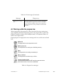
Fonts and formats
The following fonts and styles are used throughout this documentation.
xx
ECRM RIP Operator Guide
AG12325 Rev. 5
1. Paragraphs that are numbered and use this font contain instructions
which you should follow in the shown order.
Text written in this sans-serif bold face represents a menu title, a menu item, or
a control item in a RIP dialog box. Text including an angle bracket ( > ) indicates both a menu and the option in that menu. For example: “choose the
Harlequin RIP > Start Inputs option” is a shorthand method of referring to the
Start Inputs menu option in the Harlequin RIP menu.
Text written in this typewriter face represents a piece of PostScript-language
code, a file name, or text displayed by the Harlequin RIP.
If a term is written in italic, it is the first mention of an important concept. This
concept is explained in the text immediately following, in the glossary, or
both.
Note: Text indicated by starting with a bold word in the left margin is important and should be read carefully. A Note, like this one, is often a suggestion
that may save you work, improve performance, or improve the quality of
output.
Warning: Like a Note, a Warning is important and often indicates the need for
care to avoid loss of files or settings.
AG12325 Rev. 5
ECRM RIP Operator Guide
xxi
xxii
ECRM RIP Operator Guide
AG12325 Rev. 5
1
Introduction to the
Harlequin RIP
1
This chapter provides an introduction to the capabilities of the Harlequin RIP..
•
Section 1.1 on page 1 defines the Harlequin RIP.
•
Section 1.2 on page 3 describes the advantages of using the Harlequin
RIP.
•
Section 1.3 on page 4 describes various features of the Harlequin RIP.
1.1 What is the Harlequin RIP?
The Harlequin RIP is an application that takes a document or job describing
images or pages and produces output from that job on an output device—
which can be a printer, imagesetter, computer screen, or a file on disk. The
term output device is used throughout this manual, except where the nature of
the device is important.
In general, a software application or hardware device that performs this task
is known as a Raster Image Processor (RIP) or, where the PostScript language
is involved, a PostScript-language compatible interpreter.
®
The Harlequin RIP is a software RIP management system. It contains both a
software RIP and a collection of supporting functions that help the RIP perform its task efficiently. For example, the RIP accepts jobs from various
AG12325 Rev. 5
ECRM RIP Operator Guide
1
1 Introduction to the Harlequin RIP
sources, handles previewing and output of processed pages, and performs the
associated file handling.
1.1.1 Input and output formats
The Harlequin RIP accepts jobs and produces output in several formats, with
the exact options depending on your configuration of the RIP.
The range of input formats includes: PostScript-language and Encapsulated
PostScript (EPS) files, Portable Document Format (PDF) files, TIFF/IT-P1 files,
TIFF 6.0 baseline files, and JPEG and JFIF files. The Harlequin RIP supports
modern versions of these files including PostScript LanguageLevel 3, PDF
version 1.4, and derived standards such as PDF/X. The RIP also has controls
for special handling of older versions of these files if necessary.
The Harlequin RIP can produce output in a variety of formats, to suit various
physical output devices and file formats. The ability to produce TIFF 6.0 files
is a standard feature but it is easy to add output options for other formats
such as TIFF/IT-P1 files and CIP3 PPF files. Similarly, there are options for
output to many proofing printers and final output devices.
1.1.2 Versions of the Harlequin RIP
The Harlequin RIP is available in different configurations and is able to operate on different computer platforms. The configuration that is best for you
depends very much on your individual needs. This manual should help you
assess the functionality that meets those needs.
In particular, a version of the Harlequin RIP with a full graphical user
interface (GUI) is available for: Power Macintosh computers running Mac OS
8/9 and Mac OS X; computers (PCs) using Intel or compatible processors and
running Windows 98 and ME, Windows NT, Windows 2000 and Windows XP
(home and pro); computers based on the Digital Alpha processor and running
Windows NT; and various computers running the UNIX operating system.
The GUI version of the Harlequin RIP may be used on both single and multiple processor machines running the UNIX, Windows NT, Windows 2000 or
Windows XP operating systems.
This manual describes the GUI version of the Harlequin RIP for Windows NT,
Windows 2000, and Windows XP.
2
ECRM RIP Operator Guide
AG12325 Rev. 5
1.2 Why use the Harlequin RIP?
The Harlequin RIP is appropriate for a wide range of output devices including high-resolution imagesetters, lower-resolution plain-paper setters, and
medium to high-resolution printers and plotters. It supports the special features of these devices, and maximizes their overall productivity.
1.2 Why use the Harlequin RIP?
The Harlequin RIP has proven itself to be a fast, versatile, and powerful
PostScript-language compatible interpreter, and more. There are many reasons for choosing it above other similar interpreters, the most important of
which are discussed here.
The Harlequin RIP is effective, compatible, and robust; and shows real benefits in everyday use.
•
The Harlequin RIP is effective because it processes jobs quickly, is able
to process jobs of virtually any size, and can re-output selected pages or
a complete job without re-interpretation.
•
The Harlequin RIP is compatible because it is kept up to date with:
PostScript, PDF, and font specifications; image file formats; and relevant
standards from independent bodies.
Note: The Harlequin RIP is able to use proprietary extensions internally
for quality of output, speed, and efficiency without losing compatibility.
•
The Harlequin RIP is also compatible because it supports several networking protocols for use in many kinds of networks, whether or not
all the computers are of the same type.
•
Robustness comes from experience with many real jobs. You can configure the Harlequin RIP to override poor settings in incoming jobs (and
avoid office printer quality screening on expensive media), use its ability to detect poorly labeled color separations, and so on.
•
The Harlequin RIP is flexible enough to support many workflows,
including: composite or preseparated color; PostScript, PDF, or TIFF/ITP1. Some of these input formats require the Harlequin RIP options.
AG12325 Rev. 5
ECRM RIP Operator Guide
3
1 Introduction to the Harlequin RIP
A system using the Harlequin RIP is easy to extend and to upgrade when necessary because the Harlequin RIP is a software-based RIP.
•
You can add options, such as advanced screening, color management,
and trapping. In many cases you can do this by entering passwords and
in other cases with software-only procedures.
•
You can add more output options with software plugins to support
imagesetters, platesetters, proofing and display printers, and workflow
integration.
•
A PostScript-language programmer can add simple fragments of
PostScript code to provide features such as marking pages with draft or
similar overprint and color bars.
•
It is possible to upgrade hardware and software independently. The
Harlequin RIP is very similar on all platforms so there is little or no
need for retraining if you need to add another type of computer.
•
When you upgrade the Harlequin RIP you can transfer your existing
settings to the new version of the RIP and most optional output plugins.
Section 1.3 discusses many of these features in more depth.
1.3 The Harlequin RIP in depth
Section 1.2 on page 3 described some of the advantages of using the Harlequin RIP. This section describes the features that contribute to those advantages.
4
•
Characteristics of a software RIP. See page 5.
•
File format and version support. See page 6.
•
Extended color capabilities. See page 8.
•
Screening options. See page 15.
•
Harlequin ColorPro. See page 16.
•
Graphics formats. See page 17.
•
Input and output methods. See page 18.
•
Complex jobs. See page 20.
ECRM RIP Operator Guide
AG12325 Rev. 5
1.3 The Harlequin RIP in depth
•
Throughput control. See page 20.
•
Previewing. See page 22.
•
Page buffer compression. See page 22.
•
Fonts and font handling, including composite fonts. See page 23.
•
Convenience features. See page 24.
1.3.1 Software RIPs compared to hardware RIPs
Many PostScript-language-compatible interpreters are based on hardware
rather than software. That is, most PostScript-language printers come supplied with a RIP that runs on its own special hardware. Sometimes a RIP may
run on only one type of printer.
The Harlequin RIP contains a software RIP, carefully written to support a
number of computing platforms and output systems.
There are a number of advantages to using a software RIP:
•
If you have a hardware RIP and wish to take advantage of new hardware, you must either pay for an upgrade of the old hardware or stop
using it. With a software RIP such as the Harlequin RIP, you can use
your old hardware for other purposes—you still have a usable computer. Thus, taking advantage of new technology in the hardware
industry is much more cost effective if you have a software RIP.
•
You can easily take advantage of new features if you have a software
RIP. If new features are added to a hardware RIP, the only way to take
advantage of those features is to buy the new version of the hardware,
or to have a firmware upgrade. Both of these options incur considerable
time and expense. Doing the same thing for a software RIP is much simpler and cheaper—improved versions of the Harlequin RIP can be run
on the same hardware as older versions, and can be sent to you on disk.
•
When you buy a hardware RIP, you buy a dedicated machine which is
specialized for performing one task: interpreting the PostScript language. With a software RIP, the non-dedicated hardware you buy is a
computer, which can be used for many purposes other than running the
Harlequin RIP.
AG12325 Rev. 5
ECRM RIP Operator Guide
5
1 Introduction to the Harlequin RIP
•
It is much more expensive to customize a hardware RIP to individual
requirements than it is to customize a software RIP.
Even if, despite these points, you feel that a hardware RIP is still the best solution for your particular case, it need not be traditional, dedicated hardware. It
is possible to use hardware accelerators to assist a software RIP such as the
Harlequin RIP.
1.3.2 File format and version support
The Harlequin RIP supports several file formats and maintains this support
across the widely-used versions of these formats, as well as the latest versions.
Note: The Harlequin RIP limits all user created names or file names to 31
bytes. This is equivalent to 31 characters when using standard ASCII text, and
15 characters when using double-byte character sets, such as Kanji.
For example, the Harlequin RIP is a PostScript LanguageLevel 3-compatible
RIP management system but still supports features of PostScript Level 2 and
earlier. The RIP also recognizes uses of PostScript code specific to common
image creation and page layout applications.
®
The reason for supporting older versions of files and applications is that
almost all PostScript-language and PDF page descriptions are created automatically by applications. Those applications can only use the features of the
page description language as they existed at the time of writing the application, and those features are subject to change.
The PostScript language was first created and used in the mid-1980s and since
that time it has undergone many improvements and changes. Throughout this
period, people have been trying to create PostScript language page descriptions that, above all, work—despite any bugs in the interpreters which may
have existed at the time.
To cope with this situation, the Harlequin RIP is compatible not only with the
PostScript-language jobs of today, but with the jobs of yesterday. There are
two aspects to dealing with older jobs: dealing efficiently with features that
are now better supported by more modern versions of the page description
language; dealing with work-around methods for bugs in older versions of
the page description language. The Harlequin RIP does both.
6
ECRM RIP Operator Guide
AG12325 Rev. 5
1.3 The Harlequin RIP in depth
It might not be immediately obvious why it is necessary to deal with bugs and
work-around methods, but consider this example.
What happens if a bug is fixed in a widely-used PostScript language interpreter? Newer RIPs and applications no longer have to cope with that bug,
but problems arise if you wish to interpret old PostScript language page
descriptions (generated with an application written before the bug was fixed)
with your new RIP. The old page descriptions take the bug into account, but
the new RIP does not, so the hard copy produced with your new RIP is
wrong. If your RIP cannot accommodate this, as the Harlequin RIP can, your
old PostScript language files (and indeed your application if you still use it)
are useless.
The input file formats that the Harlequin RIP supports are:
•
PostScript LanguageLevel 3, Level 2, and Level 1.
•
PDF versions up to and including PDF 1.4 files.
•
PDF/X-1a:2001 and PDF/X-3:2002.
•
JPEG and JFIF.
•
TIFF 6.0 and optionally TIFF/IT-P1.
•
GIF.
•
PCL4.
See Section 5.22 on page 153 and Chapter 8, “Configuring Input” on page 227
for more details.
Note: RIP versions 5.3 and 5.5 included support for PDF/X-1:1999, this has
been dropped in the Eclipse Release of the Harlequin RIP, and replaced with
support for PDF/X-1a:2001 and PDF/X-3:2002.
The Harlequin RIP can also enable substitution of high resolution images for
PostScript-language jobs, using an in-RIP implementation of the Open Prepress Interface (OPI), versions 1.3 and 2.0, and Desktop Color Separation
(DCS), versions 1.0 and 2.0. See Section 5.20 on page 149 for details.
Additionally, the Harlequin RIP can be configured to support special features—color management, font substitution, duotones, and vignettes—of jobs
AG12325 Rev. 5
ECRM RIP Operator Guide
7
1 Introduction to the Harlequin RIP
produced by several image creation and page layout applications. These
applications include:
•
Adobe Photoshop
•
Adobe Illustrator
•
QuarkXPress
•
Macromedia FreeHand
®
®
®
®
®
See Section 5.23 on page 158 for more details.
1.3.3 Extended color capabilities
The Harlequin RIP supports the use of color capabilities introduced with
PostScript LanguageLevel 3. This support includes use of N-color or HiFi
color systems using varying number of colorants, whether those colorants
mimic CMYK systems (photo-ink systems) or use obviously different colorants.
The RIP provides separations management, preview, screening, calibration,
and plugin support for the popular N-color systems.
The RIP also has the ability to calibrate and screen spot colors separately from
process colors. This feature greatly simplifies the management of spot colors
in the RIP.
1.3.3.1 /DeviceN and N-color
The /DeviceN color space allows better control of PostScript-language code in
environments where the number of separations is no longer dominated by the
CMYK, RGB, and monochrome color models. “N” represents the number of
process color separations. Using the /DeviceN color space, CMYK corresponds to N=4, RGB to N=3, and monochrome to N=1. This color space allows
the Harlequin RIP to access separations where N=2 (duotones) or greater than
4 (N-color).
The /DeviceN color space provides the functionality to support HiFi color or
N-color systems where colorants in addition to CMYK enhance the attainable
gamut of an output process. It also provides solutions for minimizing the
number of spot colors required by an output device.
8
ECRM RIP Operator Guide
AG12325 Rev. 5
1.3 The Harlequin RIP in depth
The Harlequin RIP version 5.0 and later uses this color space to extend separations management, Roam, and plugin capabilities. Depending on your specific device and workflow, additional plugin development may be required to
make use of the expanded number of color channels.
1.3.3.2 Duotones, tritones, and quadtones
Some applications (for example, Photoshop versions 2.5 through 4) convert
duotones involving spot colors to CMYK colors when producing composite
PostScript-language jobs. While the composite output is correct, when such
jobs are submitted to a RIP that uses in-RIP separation, the duotones are
drawn on the process color separations and not on spot color separations as
expected.
Photoshop 5.0 has the ability to produce spot color separations when in-RIP
separation is selected for a LanguageLevel 3 RIP. This eliminates the problem
just described for output generated by Photoshop 5.0 when sent to any
LanguageLevel 3 RIP.
In addition to producing correct output from Photoshop 5.0 jobs, the
Harlequin RIP correctly handles jobs from Photoshop versions 2.5 through 4
as well. The Harlequin RIP detects this construct in Photoshop jobs and correctly diverts the duotone to spot color separations. Note that you must configure the Harlequin RIP to generate these spot color separations for this to
work.
For more information see Section 5.23.1, “Adobe Photoshop features”.
1.3.3.3 Patterns and Smooth Shades
LanguageLevel 3 implements new features that improve the quality of PostScript-language fills. In addition, it allows shades to be output smoothly at the
resolution of the output device target. The RIP extends this capability by
allowing for vignette replacement, in which existing vignettes in PostScriptlanguage and PDF jobs are replaced.
This functionality greatly improves the quality of gradients and shades on
output.
AG12325 Rev. 5
ECRM RIP Operator Guide
9
1 Introduction to the Harlequin RIP
1.3.3.4 Images
The Harlequin RIP version 5.0 and later supports type 3 and 4 image dictionaries (for uses such as masks). This allows an application to produce masks
using multiple images in a more efficient fashion. This mask technique also
improves performance by eliminating the need for a detailed PostScript-language clipping path. This feature is best suited to lower-resolution output
devices and workflows.
1.3.3.5 settrapparams
LanguageLevel 3 includes a new software interface that allows the description
of trap settings within a PostScript-language file.
The Harlequin RIP version 5.0 and later incorporates the settrapprams interface and uses this for setting trapping parameters. Harlequin has extended
settrapparams to include those trapping parameters that are not covered by
the 3010 specification.
1.3.3.6 Type16 halftones
The Harlequin RIP 5.0 version and later supports type 16 halftones, which can
contain more than 256 shades of gray. Harlequin has always supported an
arbitrary number of gray levels, even in the PostScript Level 1 compatible
RIPs. In the Harlequin RIP version 5.0 and later, this support for more shades
of gray is also accessible using the LanguageLevel 3 constructs.
1.3.3.7 Idiom recognition
The Harlequin RIP version 5.0 and later uses idiom recognition to detect PostScript-language procedures and replace procedures that are bound when
defined. This extends to procedures some of the benefits that Harlequin’s
shadowop operator provides for operator redefinition. Once the PostScriptlanguage code is intercepted, the Harlequin RIP replaces it with optimized
code.
This operator has many potential uses that include detecting level 2 code in a
PostScript-language file and replacing it with LanguageLevel 3 code.
10
ECRM RIP Operator Guide
AG12325 Rev. 5
1.3 The Harlequin RIP in depth
1.3.3.8 Type 32 fonts
RIP version 5.0 and later recognizes and supports Type 32 fonts.
1.3.3.9 Other operators
RIP version 5.0 and later supports the LanguageLevel 3 operators that are
defined in the 3010 LanguageLevel 3 specification. The Harlequin RIP accepts
PostScript-language output from applications using these LanguageLevel 3
operators.
PostScript LanguageLevel 3—3015—operators setoverprintmode and
currentoverprintmode were included starting with 5.5r1a version RIPs.
1.3.3.10 File filters
The Harlequin RIP supports the required file filter additions documented in
the 3010 LanguageLevel 3 specification.
1.3.4 Color, screening, and Roam functionality
RIP version 5.0 and later contains several new capabilities relating to color,
screening, and roam. Where appropriate, Harlequin has taken care to enable
the end-user to control the underlying functionality from the user interface.
Not all of the new functionality is applicable to all output devices or workflows. You will find some features more relevant than others for particular
output devices and workflow instances.
1.3.4.1 Color API
Harlequin RIP version 5.0 and later contains a programming interface (API)
that allows you to set the options for the Harlequin color management modules from PostScript-language code. This provides control over all color
options, including the installation of ICC profiles, without a user interface.
AG12325 Rev. 5
ECRM RIP Operator Guide
11
1 Introduction to the Harlequin RIP
1.3.4.2 Spot color screening and calibration
The Harlequin RIP version 5.0 and later has the capability to calibrate and
screen spot colors as well as process colors. This feature greatly simplifies the
management of spot colors in the Harlequin RIP.
1.3.4.3 UseCIEColor
This operator improves color control in the PostScript-language code by
allowing device-dependent input data to be translated to a deviceindependent CIE color space. The input colors are mapped to the device-independent color space using an input profile. The colors may then be transformed ready for printing on another output device.
Harlequin has provided this functionality for some time through the color
management modules the latest being ColorPro. You can choose to use the
color management specified in the job by UseCIEColor, or to override this
and instead use the more detailed controls provided with ColorPro.
1.3.4.4 Embedded ICC profiles
When ColorPro is enabled, the Harlequin RIP can detect and use ICC profiles
embedded in Photoshop EPS, TIFF, or JPEG images. See the ColorPro User’s
Guide for details.
1.3.4.5 Colorimetric roam
Provided a system is using an sRGB display (monitor and display card) and
the monitor is properly calibrated, Roam approximates colorimetric output on
the display.
1.3.5 Memory management
Harlequin has a continuous program for improving the performance of the
Harlequin RIP memory management. A new architecture has been put into
place within the Harlequin RIP 5.0 and later for the Windows, UNIX (IRIX,
Solaris), and Macintosh platforms. This architecture not only provides the
groundwork for future memory features and enhancements, but also allows
for a level of dynamic memory management within the Harlequin RIP.
12
ECRM RIP Operator Guide
AG12325 Rev. 5
1.3 The Harlequin RIP in depth
There are new GUI controls for setting memory. As in the past, it is possible to
specify the memory used by the Harlequin RIP, but there is a significant difference.
•
In previous versions, the Harlequin RIP put a claim on the entire
amount of memory specified so that the operating system and other
applications could not use this memory even if the Harlequin RIP did
not require it at a particular time. (The Macintosh implementation,
because of operating system differences, varied slightly with respect to
this functionality.)
•
With the new implementation, the specified memory is not held exclusively for the Harlequin RIP. Instead, the Harlequin RIP takes only the
amount of memory it requires at the time. This amount rises while processing a job but once the job is processed the memory is returned to the
system. This allows the Harlequin RIP to co-exist better on a system
with the operating system and other applications.
The new implementation also makes it possible to specify a reserve amount of
memory, available for short-term use by the Harlequin RIP. For example, the
Harlequin RIP may use this reserve in time-critical operations, where the
alternative would be to use disk storage, as long as the reserve is large enough
to keep the operation in memory.
1.3.5.1 Garbage collection
With the Eclipse Release of the Harlequin RIP, garbage collection has been
implemented. Garbage collection is performed when memory is low and
reclaims the memory occupied by composite objects that are no longer accessible to the PostScript program.
This helps some jobs that allocate a lot of memory, but not all. Some jobs that
could not partial paint will now need significantly less memory than before.
When garbage collection starts, a message is displayed on the console window.
Garbage collection is controlled using the PostScript Language operator
vmreclaim.
AG12325 Rev. 5
ECRM RIP Operator Guide
13
1 Introduction to the Harlequin RIP
For more information on garbage collection, see section 3.7.4 of the The
PostScript® Language Reference (3rd Edition).
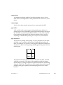
1.3.6 Headless RIP Option
The headless RIP functionality that was introduced in Harlequin RIP versions
4.5 and 4.6 is also available in Harlequin RIP 5.0.
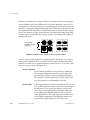
1.3.7 FlatOut
RIP version 5.0 and all subsequent Harlequin RIP 5 releases are capable of
stitching single-page PGB files into a predefined flat. This feature enables the
development of page-based workflows around the Harlequin RIP.
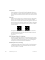
Three components are required to produce a stitched flat:
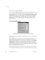
1. A background PGB file. You can create a background in a page layout
application and then convert the PostScript-language code to a PGB
using the Harlequin RIP. This flat background contains a slot for each
page. This background may contain sluglines, crop marks, and so on.
2. Single-page PGB file(s). For example, to produce an eight-page flat, eight
single-page PGB files must be generated.
3. A flat description file. This file describes the location of the background
and single-page PGB files on disk. The flat description file also indicates
the positioning of pages on the flat.
The flat description file is presented as an input to the Harlequin RIP and the
PGB files are stitched into a single flat for output to the specified output
device.
The Harlequin RIP version 5.0 and later accepts PGB files from Harlequin
RIPs version 4.5. It also accepts PGB files from any other Harlequin RIP platform. This extends the ability to interchange PGB files between Windows platforms, which was introduced in the Harlequin RIP 4.5.
For additional information on how to generate a flat description and more on
PGB stitching, please refer to the FlatOut User Guide.
14
ECRM RIP Operator Guide
AG12325 Rev. 5
1.3 The Harlequin RIP in depth
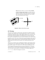
1.3.8 Screening options
The Harlequin RIP has several screening features and options, designed to
produce high quality output on devices ranging from imagesetters to inkjet
proofing printers. There is generalized screening support for color systems
that go beyond straightforward CMYK process colors, but you need an output
plugin and device able to support these color systems.
The Harlequin RIP is able to create extra gray levels (with HPS) and to control
the number of extra levels, even with PostScript Level 1 jobs. This feature
helps to eliminate stepping in vignettes and to avoid posterization, while
enabling you to set a limit on the number of levels that is appropriate to the
required image quality. The RIP also supports more than 256 shades of gray
when they are specified using PostScript LanguageLevel 3 constructs.
1.3.8.1 Harlequin Precision Screening
For very high quality output, Harlequin Precision Screening (HPS) has been
produced. This is a proprietary feature that eliminates objectionable moiré
patterning when producing color separations.
Once correctly set up, and with sufficient memory available, the Harlequin
RIP can produce output with HPS at speeds comparable to those obtained
when using traditional lower-quality rational tangent screening.
HPS has been designed for automatic operation, without the need to refer to
complex tables of magic numbers, and you can choose to override any bad
settings in the job. This is especially useful for print bureaus, who often
receive PostScript-language code that is not set up for high quality screening.
1.3.8.2 Harlequin Screening Library
Global Graphics has developed a number of special screening strategies for
very high quality press work, particularly when printing in color. They are
included in the Harlequin Screening Library (HSL), and require separate passwords to become enabled.
HSL includes Harlequin Dispersed Screening (HDS), Global Graphics’s patented Frequency Modulation (FM) screening technology. Moiré patterning is
impossible with HDS, and it gives finer detail for a given device resolution.
AG12325 Rev. 5
ECRM RIP Operator Guide
15
1 Introduction to the Harlequin RIP
Also included are Harlequin Chain Screening (HCS), which is particularly
good at creating smooth flat tints and at holding detail in continuous tone
regions, and Harlequin Micro Screening (HMS) which allows a greater range
of tones to be used even at high screen rulings.
1.3.8.3 Screening for extended color systems
Several color systems require more than the four screens used for CMYK
work. The Harlequin RIP contains screens suitable for use with HiFi color systems such as the PANTONE Hexachrome Color Selector system or the various photo-ink technologies using different densities (light and dark versions)
of one or more colorants.
®
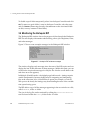
1.3.9 Harlequin ColorPro™
It is possible to add and use the advanced color management facilities provided by Harlequin ColorPro which as an optional extra provided with the
Harlequin RIP and requires a password for it to be enabled
ColorPro is a comprehensive color management system which replaces all the
previous offerings such as HIPP, HCMS, HFCS and HCPS.
ColorPro together with SetGoldPro profile making software is Global
Graphics’ color science solution for ensuring color quality and accuracy for
proofing and emulation. ColorPro provides the largest realizable color gamuts
for the final print market and allows greater accuracy than would be possible
using standard profiles.
™
Harlequin ColorPro embraces open systems, industry standards and deviceindependent color science, and is able to make full use of them. If you have
ICC profiles with which you already achieve good results you can use these
profiles with ColorPro. You should however be aware that ColorPro contains
color science that is optimized for the Harlequin RIP and is easily utilized
with the introduction of SetGoldPro.
ColorPro allows you to specify different gamut-mapping algorithms in the
reproduction of a page. For example, you can simultaneously specify Absolute
colorimetric to reproduce some elements of the page and yet specify Perceptual
to reproduce the photographs. The end result is that, on a single page, the
16
ECRM RIP Operator Guide
AG12325 Rev. 5
1.3 The Harlequin RIP in depth
color for photographs are each calculated without affecting other elements on
the page.
Harlequin ColorPro allows processing of colors in page data using ICC
profiles produced by s, third parties, or end-users using third party characterization and profiling tools. ICC profiles specify a translation between two
color spaces. Each profile is prepared for a specific set of imaging conditions.
One device may have more than one profile. The profiles may correspond to
running the device with different combinations of resolutions, inks, and
paper.
New profiles can be easily added to ColorPro, and previously installed
profiles can be selected without the need to reinstall each time a profile is
used.
An option to uninstall ICC profiles is also provided.
In addition, ColorPro allows the use of profiles prepared in the Harlequin RIP
format. Global Graphics supplies a number of profiles for commonly used
systems.
When ColorPro is enabled, the Harlequin RIP can detect and use any ICC profiles that Photoshop has embedded in EPS, TIFF, or JPEG images.
This manual describes the Harlequin RIP without ColorPro, but mentions
areas where ColorPro would modify your use of the Harlequin RIP. The extra
facilities are described in the separate manual Harlequin ColorPro User’s Guide.
For information on color facilities provided in the Harlequin RIP as standard
see Section 12.8 on page 388.
1.3.10 Graphics formats
The Harlequin RIP can produce halftone output, 8-bit grayscale output, 8- and
10-bit run-length encoded (RLE) output, and color contone (continuous tone)
output in N-color, CMYK and RGB formats. This allows the RIP to be used for
driving contone color printers as well as imagesetters.
This output is passed to an output plugin (described in Section 1.3.11), and
from there to the output device controlled by that plugin. Output devices are
often physical printers producing images on paper or film; but devices can
also be files on disk, storing the images in a specific graphics format.
AG12325 Rev. 5
ECRM RIP Operator Guide
17
1 Introduction to the Harlequin RIP
An output plugin that creates disk files provides a simple method of translating from the input format to another graphics format. Using such an output
plugin extends your ability to transfer graphics defined in the PostScript language or PDF to other software applications or systems. For example, you can
produce a graphics image without dependencies on external fonts or color
management. Also, you may wish to send a page description to someone who
does not have access to PostScript-language tools but who can use files in the
Tagged Image File Format (TIFF). TIFF is a commonly-used graphics format
and a TIFF output device is supplied with the RIP.
1.3.11 Input and output methods
The Harlequin RIP performs most of its input and output using plugins, small
auxiliary programs that the RIP loads when it starts up.
You can install new plugins into an existing installation of the Harlequin RIP
to add new input and output capabilities. Several optional plugins are supplied with an installer program, and it is always better to use an installer if it
exists, but the basic operation is file copying.
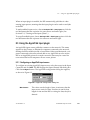
1.3.11.1 Output plugins
The RIP sends all output to printers and other output devices through output
plugins, thereby allowing the quick and straightforward addition of support
for new output devices.
Typical output plugins support single output devices or families of similar
devices and may be supplied with special screens, calibration and color management, and other features appropriate to the device, such as control of exposure or cutting media.
Optional output plugins support file formats useful in workflow systems,
advertising distribution, and setting up printing presses. These formats
include TIFF/IT-P1 and the CIP3 Print Production Format (PPF).
1.3.11.2 Input plugins
Input plugins provide communication between the Harlequin RIP and other
systems, primarily as sources of input.
18
ECRM RIP Operator Guide
AG12325 Rev. 5
1.3 The Harlequin RIP in depth
The standard input plugins provided with the Harlequin RIP include:
•
AppleTalk
An AppleTalk network connects together a mixture of Apple and other
computers and printers in order to share disk resources and printing services. AppleTalk runs on LocalTalk and Ethernet and is a widely supported network protocol.
AppleTalk networks often include multiple printers, available to
Macintosh OS 8/9 users through a list in the Chooser desk accessory.
Because the Harlequin RIP behaves as any other printer on AppleTalk,
you can send print jobs to the RIP running on a machine connected to
the AppleTalk network, in the same way as any other printer. (The Harlequin RIP can emulate several, differently configured, printers if you
wish.)
•
Spool Folder
This plugin allows you to set up the Harlequin RIP so that it continually
scans or polls a folder (directory)—for example, on a central server—for
input files. When these files appear and are complete, the RIP processes
them. The spool folder uses the network file access provided by your
machine—for example, Network File System (NFS) on machines running the UNIX operating system. You can use multiple configurations
(as described in “Multiple inputs” on page 20), allowing you to have
several scanned folders, each with a different associated page setup.
•
NT Print
This publishes the Harlequin RIP as a printer available to the
Windows NT print services.
•
NT Pipe
This provides a named pipe allowing high speed communication with
an application such as an Open Prepress Interface (OPI) server.
•
Serial Port
With this plugin, PCs and other computers can be connected using their
serial ports and communicate with one another. The data transfer speed,
however, is very slow. This plugin supports the Adobe Serial Lines
Protocol.
AG12325 Rev. 5
ECRM RIP Operator Guide
19
1 Introduction to the Harlequin RIP
•
Sockets
With this plugin, the Harlequin RIP can accept input from a network
socket client program, which may be part of a larger workflow system.
This plugin supports TCP/IP and UNIX socket protocols.
1.3.11.3 Multiple inputs
For some input types, it is possible to have available several configurations or
page setups (where parameters such as resolution, output device, rotation, and
negation are given specific values). Using AppleTalk, several different virtual
printers can be made available on the network using a single running copy of
the Harlequin RIP, each printer with a different page setup. When using the
Spool folder plugin, several spool folders can be made available, each with an
associated page setup.
You can enable multiple types of input allowing, for example, AppleTalk and
Spool folder inputs to operate at the same time.
1.3.12 Complex jobs
Given enough memory and disk space, the Harlequin RIP can interpret arbitrarily complex jobs. The same is not true for many other high resolution RIPs.
This is achieved with a feature called partial page buffering (or “painting partial
pages” in some messages). Essentially, if a particular job is so large that it cannot all be fitted into memory at once, the RIP interprets only as much of the
page description as does fit into memory, and places the interpreted image in
a partial page buffer. Having dealt with part of the image, the RIP gains
enough free memory to deal with the next part—the effect being that the page
description is divided into manageable sections, which are interpreted one at
a time. Disk space is used to hold what has been interpreted so far until the
whole image has been processed, and printing can commence.
1.3.13 Throughput control
In almost all circumstances, it is desirable to produce page images as quickly
as possible while maintaining high quality. All Harlequin RIPs are written
with this aim in mind and can benefit from operating with fast hardware.
Beyond this, and especially when using high resolution imagesetters, special
20
ECRM RIP Operator Guide
AG12325 Rev. 5
1.3 The Harlequin RIP in depth
techniques can help maximize the rate of producing useful output. The
Harlequin RIP can use these techniques, collectively called throughput control,
when either of the multiple page buffering modes is selected. See Section 4.2
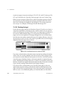
on page 78 for more details of multiple and single page buffering modes.
The Harlequin RIP increases job throughput in two ways.
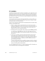
Firstly, the RIP differs from other RIPs in the way bitmaps are produced and
sent to an output device. A traditional RIP must interpret a page and send the
bitmap directly to the output device before continuing with the next page.
Because of this, if you have to change cassettes or some fault occurs with the
output device, the current page cannot be output until the fault is cleared; productive work stops until the situation is resolved.
The Harlequin RIP can be operated in this way if desired, but it offers a powerful alternative that overcomes these limitations—by saving bitmaps on disk
in the form of page buffers, before bitmaps go from the disk to the output
device. Many page buffers can be stored on disk (as many as will fit into the
available disk space), and the RIP can continue to produce and save page buffers, even if the device is not ready to output. If a printer jam occurs in an overnight job, the RIP is still able to process the job and the page buffers are ready
for output the next day. In a high volume environment, this ability can be
invaluable.
Even when there are no problems with the output device, you can still save
time—if you need to produce more than one copy, you do not need to reinterpret the page description, because the bitmaps are still retained on disk. This
means, for example, that if a page gets damaged in the developer or there is a
problem with ink delivery then it is easy to print another copy.
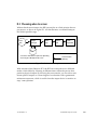
Secondly, the Harlequin RIP increases job throughput by allowing job interpretation and output to occur simultaneously. While some pages of a job are
being interpreted, other pages, which have already been interpreted, can be
sent to the output device. This can greatly increase throughput when outputting several pages in succession. With a fast computer, it is possible to drive
the imagesetter continuously for several pages. Even with fast output devices,
time can be used effectively, because the RIP can be interpreting data while
the output device starts up.
AG12325 Rev. 5
ECRM RIP Operator Guide
21
1 Introduction to the Harlequin RIP
1.3.14 Previewing
The Harlequin RIP allows you to preview pages, at their output resolution on
screen to check them for mistakes before they are output, at their full output
resolution. You can preview halftone, contone and grayscale images using the
full color capabilities of the display system.
You can request a reduced view of the entire page in a separate window. This
provides a better idea of what the whole page looks like, and also acts as a
navigation aid to help you to display any part of the page at full resolution, to
check fine detail.
The remaining functionality depends on the page buffering mode. (Section 4.2
on page 78 describes page buffering modes.)
Using either of the multiple page buffer modes, you can view several separations or pages, overlaid or separately. This allows a good check of the page,
including checking image positioning, trapping, and so on. You can view separations in their natural colors, thus obtaining a realistic impression of final
output, or in false colors, to highlight differences between similar separations
or composite pages.
In either of the single page buffer modes, you can view only individual separations or a composite image, and only in the natural colors.
1.3.15 Page buffer compression
When producing jobs at high resolutions or on large format devices, large
amounts of disk space are often required if page buffers are used. The RIP
makes the most of the available disk space by compressing page buffers as
they are created and placed on disk, and then uncompressing them as they are
read from disk and printed or displayed.
Compression saves a great deal of disk space and often means that large jobs
can be printed without stopping the imagesetter, because compressed data
can be read from disk more quickly. Stopping an imagesetter part way
through a job can lead to a loss in output quality, so this facility can be of great
benefit. (See the description of data underrun on page 98, which explains one
problem that page buffer compression can help avoid.)
22
ECRM RIP Operator Guide
AG12325 Rev. 5
1.3 The Harlequin RIP in depth
Page buffer compression always produces buffers of the same size as or
smaller than the original. For color pages, it typically achieves a compression
ratio of 3:1, and for newspaper pages a typical ratio of 10:1. That is, the compressed page buffer could be less than a third of the size of an uncompressed
one for color pages, and a tenth of the size for newspaper pages. For color
images, this can mean reducing disk requirements from 150 MB to only
50 MB.
Page buffer compression in the RIP is a completely lossless procedure. The
quality of your output is fully preserved when compressing and then uncompressing the page buffers. For details of the amount of disk space you need to
reserve for page buffers, see “Ability to RIP a job” on page 38.
From version 5.5 files greater than 2 GB can be read and written. The most
likely use of this is the ability to generate page buffers greater than 2 GB.
1.3.16 Fonts and font handling
To print text, the relevant fonts must be installed in a RIP before interpreting a
job, or the fonts must be supplied with that job.
If the interpreter sees that a Times-Roman font is needed for a particular job, it
must know what a Times-Roman font is. The Harlequin RIP comes ready-supplied with the 35 standard fonts found on most PostScript-language printers
and several additional fonts. (See page 300 for a description of the supplied
fonts.) Thousands of other fonts are commercially available, as is software to
help you design your own fonts from scratch. The RIP can load any PostScript
font into the RIP for use in interpretation (unless the font is encrypted using
some proprietary encryption mechanism).
The Harlequin RIP enables you to download, list, and proof fonts easily and
quickly. You have complete control over which fonts are loaded when the RIP
is run, and can remove any unwanted fonts at any time.
The Harlequin RIP can convert any Type 1 PostScript font into its own format,
DLD1. DLD1 fonts consume much less memory and disk space than normal
Type 1 descriptions, and so reduce processing time—but with no change in
output quality.
AG12325 Rev. 5
ECRM RIP Operator Guide
23
1 Introduction to the Harlequin RIP
The 35 standard hinted fonts are provided with the Harlequin RIP in DLD1
format. Font hinting is essential when previewing images or printing at low
resolution, where it greatly improves the quality of the output.
1.3.16.1 Composite fonts
The Harlequin RIP supports composite fonts, in both Original Composite Format (OCF) and Character Identifier (CID) formats, which allow you to use
large or complex fonts such as those for Chinese, Japanese, or Korean characters. Composite fonts support large character sets and are especially important in the Far East.
There are several features to allow easy composite font installation without
requiring complex structuring of the fonts. Also, because of the high value of
such complex fonts, the Harlequin RIP provides a way of encrypting fonts, so
that they can only be used with a particular copy of the RIP.
1.3.17 Convenience features
The Harlequin RIP provides some useful facilities for monitoring media on
cassette-loaded devices such as imagesetters and for using or testing fragments of PostScript code. These fragments, page features, can do such things as
labelling output or performing basic imposition and media saving.
Most of these facilities require little or no knowledge of the PostScript
language.
1.3.17.1 Media management
Output devices vary greatly in the type of output media they can use and the
amount of manual intervention required. Some devices use a single source of
roll-fed or sheet-fed material and the output is ready to use, while other
devices can accept media from a variety of sources or require processing of the
output. Equally, different users make very different demands on their imagesetters with respect to film and paper handling.
The Harlequin RIP includes a sophisticated media manager.
For example, you can keep track of the media left on the rolls of up to sixteen
input cassettes; a variety of materials and media widths can be set, and the
24
ECRM RIP Operator Guide
AG12325 Rev. 5
1.3 The Harlequin RIP in depth
system allows you specify automatic media cutting at predetermined places,
such as after a particular number of pages or before the take-up cassette gets
too full.
In addition, the Harlequin RIP warns you when a cassette is nearly empty,
and allows you to define how much space should be left between pages,
between jobs, and between film cuts. It will even save media by automatically
rotating pages to use the minimum amount of film.
New for version 5.5 is a Media Saving feature. For more information see
Section 5.14 on page 138.
1.3.17.2 Page features
Sometimes you may want to apply a special effect to your jobs. For example,
you may want to have the word Draft overprinted on every page. Because
these can be one-off needs—you may want to produce a special copy of a document while it is at draft stage—it is preferable not to alter the job if at all
possible.
The Harlequin RIP provides this facility by allowing you to specify a fragment
of PostScript-language code, independent of your main job, to be processed in
conjunction with it. A fragment such as this is known as a page feature.
A page feature carries out some process on your job, leaving the original
untouched. Often, the effect of the process is to produce a desired printed
effects but some page features produce no printed output because their purpose is to report some properties of the job.
A number of page features are provided with the Harlequin RIP for immediate use or as examples. You can choose any of those for immediate use from a
menu in a dialog box. See Section 5.20 on page 149 for details.
As with plugins, you can add new page features by placing them in a particular folder. .
1.3.17.3 Interactive sessions
The Harlequin RIP has a feature known as the executive, which allows you to
run an interactive PostScript-language session. This means that you can type
AG12325 Rev. 5
ECRM RIP Operator Guide
25
1 Introduction to the Harlequin RIP
fragments of PostScript-language code and have them interpreted immediately. This can be very useful when debugging and testing small parts of jobs.
The executive feature is available in the Harlequin RIP on all supported
platforms.
1.3.17.4 Page imposition
Page imposition is the process of laying out several pages of a document on
one large sheet of paper or film. Using a combination of PostScript-language
operators and an extension to the language, it is possible to take several pages
and produce output on a large sheet of paper, each page being printed in an
orientation and position determined by you.
Page imposition can be useful both for saving media—pages can be orientated
so as to use the optimum amount of paper—and for printing pre-imposed
sheets of paper, for instance when printing a book where certain pages are
made out of the same piece of paper. Some understanding of the PostScript
language is useful here, but the Harlequin RIP is supplied with several imposition templates which can be used immediately.
26
ECRM RIP Operator Guide
AG12325 Rev. 5
2
Running the Harlequin RIP
2
This chapter is a short guide to getting the Harlequin RIP running on your
machine. It does not contain complete installation details because these differ
between different combinations of computer, operating system, and output
device. For full details, see the separate ECRM RIP Getting Started Guide for
your platform (combination of computer and operating system).
This chapter provides details for the following:
•
Machine requirements, described in Section 2.1.
•
Connecting your machine to an output device, described in Section 2.2
on page 33.
•
The files and folders used by the RIP, described in Section 2.3 on
page 34.
•
Starting up the Harlequin RIP and an introduction to the standard
menus and dialog boxes, described in Section 2.4 on page 39.
•
Some menus that appear only when options are enabled, described in
Section 2.5 on page 45.
•
Stopping the Harlequin RIP, described in Section 2.6 on page 47.
AG12325 Rev. 5
ECRM RIP Operator Guide
27
2 Running the Harlequin RIP
2.1 Machine requirements
This section covers the hardware requirements that you need to run the
Harlequin RIP. Do not worry if you are not familiar with the RIP technical
terms used in this section. As you work through the manual, all of these terms
will be explained. The “Glossary” on page 441 explains many of these terms.
Hint: Follow the basics of this section on first reading to get a working installation of the RIP. When you are more familiar with the RIP, use this section for
reference, so that you can improve the RIP’s performance in your environment.
2.1.1 Performance
For a given processor type and speed, the most important things affecting the
performance of the Harlequin RIP are the built-in or physical memory (RAM)
and the speed and size of disks.
It is recommended that you use a 450 MHZ Pentium based PC running
Windows NT, Windows 2000 or Windows XP with 256 MB or more of random
access memory (RAM) and a minimum of 4 GB of free disk space.
In addition the following points should be considered:
•
There must be sufficient space to hold page buffers on disk.
•
There must be sufficient PostScript-language virtual memory available
for the job. This is especially important when using composite fonts.
•
For some output devices, a disk with a certain minimum performance
may be required.
Important: The general rule is that the more memory, the better the performance. Note especially that if you use the following features, we recommend
that you add extra RAM:
28
•
Add an additional 8 MB RAM for each composite PostScript font used
in a single job.
•
Add an additional 12 MB RAM for when using Harlequin Precision
Screening (HPS).
•
Add an additional 256 MB RAM when using TrapPro or TrapProLite.
ECRM RIP Operator Guide
AG12325 Rev. 5
2.1 Machine requirements
•
Add an additional 32 MB RAM for EDS Screening in the output plugin.
•
When using Harlequin ColorPro, add extra RAM. The required amount
can vary according to the functions you use.
•
There are some instances when the Harlequin RIP cannot paint partial
page buffers to disk: for example, when recombining preseparated jobs
or using TrapPro. In such cases, the RIP will need extra memory and
must have enough memory to complete the job. See Section 7.10, “Harlequin RIP memory allocation”, the TrapPro User Manual and ECRM RIP
Getting Started Guide for details.
•
For large format devices, more memory may be required.
In general, if a job uses more than one of these features, add together the extra
memory required by each feature. For example, if a job uses composite fonts
and you are using HPS add together the extra amounts of RAM. You will also
need enough extra RAM to accommodate any printer and network buffers
you want to set up.
For more details, see Chapter 6, “Screening”, Chapter 7, “Configuring the
RIP”, and Chapter 10, “Fonts”.
Note: This manual uses conventions of font and style to describe special key
combinations and to highlight the titles of programs, options in menus and
dialog boxes, and text that we suggest you type. For details, see the
“Conventions” on page xiv in the Preface.
Windows NT, Windows 2000 and Windows XP use disk space as virtual
memory.
For Windows NT Version 4.0, Windows 2000 and Windows XP, the defaults
suggested when you install Windows are satisfactory for use with the Harlequin RIP. If you later install more disk space or memory, you should update
the virtual memory setting. To do this, open the System control panel and display the Performance tab. In the Virtual Memory section, click the Change button
and use the recommended figures.
In summary, as well as the memory and disk allocations discussed here, the
performance of the RIP also depends on the following:
•
The speed of the processor.
AG12325 Rev. 5
ECRM RIP Operator Guide
29
2 Running the Harlequin RIP
•
The amount of additional RAM on your machine. (Additional RAM is
RAM above the basic requirement.)
•
The disk speed of your machine.
•
The interface used to send data to the output device, especially if it is a
high-performance device.
Performance issues are described throughout this manual, but see especially
Chapter 7, “Configuring the RIP”, and Appendix A, “Troubleshooting”, for
details about optimizing the performance of your hardware.
For further details on machine specifications you should consult the relevant
installation guide.
2.1.2 Ability to RIP a job
Depending on what page buffer mode you choose, the Harlequin RIP will
usually create one or more page buffers on disk when you process any job (see
Chapter 4, “Harlequin RIP Output Methods”, for full details). This allows the
RIP to print any job on a machine of any performance, no matter how complex
the job is. The only requirement for your machine (apart from a minimum
requirement of RAM) is that it must have sufficient free disk space to hold
these page buffers.
By default, the Harlequin RIP compresses page buffers as it creates them: the
compression is always lossless and does not affect the output quality in any
way. This compression can reduce the disk space required to anything from
half to a tenth of the uncompressed file, or even less. However, you do not
have to compress page buffers if you do not wish to. See Chapter 7, “Configuring the RIP”, for full details.
Note: Crop marks can greatly increase the actual size of the page (by adding
largely blank surrounds to the image) and hence create a need for more disk
space. If you ask the Harlequin RIP to compress page buffers as they are created, the extra space required by crop marks compresses well, as does the
other blank space between text and images.
Typical free disk requirements, for both compressed (C) and uncompressed
(U) page buffers, are shown in the following table, giving details for output at
different resolutions and for different page sizes. These figures are for halftone
30
ECRM RIP Operator Guide
AG12325 Rev. 5
2.1 Machine requirements
page buffers holding a monochrome page or one separation of a separated
page. All figures are given in MB.
US Letter
Resolution
A4
Tabloid
A3
Broadsheet
U
C
U
C
U
C
U
C
U
C
300 dpi
1.00
0.20
1.00
0.20
2.00
0.40
2.10
0.41
4.60
0.93
400 dpi
1.70
0.36
1.80
0.37
3.60
0.71
3.70
0.74
8.20
1.60
600 dpi
4.00
0.80
4.10
0.83
8.00
1.60
8.30
1.70
19.00
3.70
800 dpi
7.10
1.40
7.40
1.50
14.00
2.90
15.00
3.00
33.00
6.60
900 dpi
9.00
1.80
9.30
1.90
18.00
3.60
19.00
3.70
42.00
8.30
1200 dpi
16.00
3.20
17.00
3.40
32.00
6.40
34.00
7.20
74.00
14.80
1524 dpi
26.00
5.20
27.00
5.40
52.00
10.40
54.00
10.80 120.00
24.00
2400 dpi
64.00
12.80
68.00
13.60 128.00
25.60 136.00
27.20 296.00
59.20
20.80 108.00
21.60 208.00
41.60 216.00
43.20 480.00
96.00
3048 dpi 104.00
Table 2.1 Typical free disk requirements for page buffers
Contone page buffers or composite color page buffers are bigger than monochrome page buffers when uncompressed, by a combined factor taking
account of the number of bits used per color and the number of colors in the
page buffer. For example, when uncompressed, a four-color page using 8 bits
per color (256 tonal values) would use 32 times more memory than the figures
given here. It is harder to predict the relative sizes of compressed page buffers
because the contents of the page have a large effect. For example, the compression ratio achievable for a page filled with an unchanging background tint is
likely to be better for a contone page buffer than for a halftone page buffer.
In addition, you must ensure you have enough disk space to hold workspace
for processing the scanned images on any one page of your job. For example,
when printing the Seybold Musicians test job (a full-color scanned image),
8 MB of extra disk workspace will sometimes be required in addition to the
figures shown above. (Whenever possible, the Harlequin RIP uses RAM in
preference to disk space.)
If you have spare memory after allocating memory for the considerations
described in “Performance” on page 28 and in the separate ECRM RIP Getting
Started Guide, you may be able to use this surplus to create a RAM disk in
which to place page buffers. To be useful, the RAM disk must be at least large
AG12325 Rev. 5
ECRM RIP Operator Guide
31
2 Running the Harlequin RIP
enough to hold a single page buffer, and if you want to use throughput (using
either of the multiple page buffer modes), it should ideally be large enough to
hold at least two page buffers.
For 2540 dpi color work, a RAM disk of around 100 MB is desirable. For
1016 dpi monochrome output, a RAM disk of around 30 MB may be enough.
2.1.1 Driving a printer effectively
The machine requirements discussed so far have concerned the production of
a page buffer. Meeting these requirements is sufficient for you to view the
page buffer on screen or for the Harlequin RIP to convert it into a file in a useful graphics format.
When you want to convert the page buffer to an image on physical media, you
must transfer the data to an output device. This transfer is another factor
determining overall performance and often imposes other requirements on
the computer system running the RIP.
Many output devices need data to reach them at a sustained high speed; in
general, this speed becomes higher and harder to achieve as the resolution of
the device increases. Table 2.2, page 32, shows examples of required data
transfer rates (in kilobytes per second) for typical output devices supported
by the various versions of the Harlequin RIP.
Rate
(KB/s)
Resolution
(dpi)
Output device
200
300
Large format inkjet printer
2000
300
Dye-sublimation printer
750
2400
Slow imagesetter
1500
1270
Fast imagesetter
8000
4000
Large format drum recorder
Table 2.2 Required data rates for typical output devices
With simple jobs, these data rates can be achieved without using a page buffer
on disk. However, with complex jobs, a page buffer may be required, which
means that the disk on your computer must be fast enough to supply data at
32
ECRM RIP Operator Guide
AG12325 Rev. 5
2.2 Installing printer interface cards
these rates. If the disk is too slow and your printer is not capable of stop /
starting without abandoning the page, it is not possible to output the whole
page. If your printer can stop / start in the middle of a page, then achieving
the required data rate is less important, but the quality of the output may still
be affected, depending on the device.
When you look at the data rates in this table, note the following:
•
The disk speed of your machine must be slightly faster than the data
rate of the output device in order to drive it successfully—the extra
speed allows for the overhead of transferring the output to the printer.
For example, a machine with a disk speed of 1.3 MB/s may be required
to drive a slow imagesetter at 750 KB/s.
•
To smooth out peaks and troughs of disk performance and other system
and RIP functions, the Harlequin RIP uses a printer buffer in memory.
Typically, you should make this buffer large enough to hold between 5
and 10 seconds of output to the device: for example, 7.5 MB for a device
that outputs at 750 KB/second. You can set the size of the printer buffer
in the Configure RIP dialog box: see Chapter 7, “Configuring the RIP”.
We strongly recommend that you use compressed page buffers. If this is done,
the Harlequin RIP can achieve higher data rates because less data has to be
read from disk. Compressing page buffers also lets you run the RIP on a
slower disk than would be required were page buffers not compressed. There
are very few situations where it is not desirable to compress page buffers.
2.2 Installing printer interface cards
If you want to produce output on a printer or imagesetter, there must be a
suitable way of connecting the output device to the computer running the
Harlequin RIP. Many low or medium resolution devices can connect to standard communications ports or printer ports on your computer. Using a high
resolution or high speed output device may mean that you must install a special printer interface card in the computer.
There should be installation instructions supplied with any interface card and
there are some general guidelines in the separate ECRM RIP Getting Started
Guide for each platform.
AG12325 Rev. 5
ECRM RIP Operator Guide
33
2 Running the Harlequin RIP
2.3 Harlequin RIP folder structure
The folder in which the Harlequin RIP is installed contains the Harlequin RIP
application itself, and a folder called SW, as well as other support files. The SW
folder contains the files that the RIP needs in order to run, such as device
driver files, PostScript-language header files, and fonts. You can install new
device drivers, features, and so on—in many cases by placing the relevant
folders or files directly into the appropriate folder, but it is safer to use a supplied installation program if there is one.
Warning: Do not delete any files from the SW folder, except in the limited cases
where this manual or the Harlequin RIP support staff advise you to do so.
Note: Installing the Harlequin RIP creates some of the following items immediately: other items are created later, as required by later reconfiguration of
the RIP or the use of particular options such as screening features or spooled
input.
The SW folder contains the following items:
34
•
The caldata folder, which is created when you first use the Output >
Print Calibration menu option to print a calibration target, and is
updated as you print more targets. This folder holds files and folders
describing the printed targets. If you use the Genlin program to measure a printed target, it generates a file of results in this folder.
•
The categories folder contains the categories resource.
•
The charstrings folder contains the file StandardCharStrings, which
contains the standard name-to-character mappings used by most fonts.
Other mapping files may also be stored here.
•
The CIDFont folder contains fonts defined in the CID (character identifier) format.
•
The CMap folder contains information for use with CID fonts.
•
The colorrenderings folder contains color rendering resources.
•
The colorspaces folder contains resources for the color spaces defined
in the Harlequin RIP.
•
The Complete folder is provided as a default location for the spool
folder input to place files that it has successfully processed.
ECRM RIP Operator Guide
AG12325 Rev. 5
2.3 Harlequin RIP folder structure
•
The Config folder contains all the configuration files for the Harlequin
RIP. These include files detailing such things as the current page setup
and Configure RIP settings, as well as folders for information including
the configuration for available devices, default color profiles, and target
definitions.
In the Config folder, the Factory Settings subfolder contains the
default configuration for the Harlequin RIP when it is shipped. This is
essentially a copy of the Config folder itself.
In the Config folder, the Page Setups subfolder contains all the page
setups you have saved within the Harlequin RIP.
•
The Crdgen folder contains the color rendering dictionary (CRD) generator plugin executables. You can only manipulate CRDs in the
Harlequin RIP with the ColorPro option enabled.
•
The Devices folder contains all the output plugin files (possibly within
subfolders) for the various output devices.
•
The encodings folder contains the font encodings for the fonts installed
in the RIP.
•
The Error folder is provided as a default location for the spool folder
input to place files that it cannot process.
•
The Extensions folder can contain folders or files used to implement
extensions to the RIP.
•
The FlatPgbDir folder provides space for the page buffer files used by
FlatOut. See the FlatOut User Guide for details.
•
The fonts folder contains fonts used by the Harlequin RIP (including
the fonts installed with the RIP).
•
The FontSet folder is used for PostScript LanguageLevel 3 font sets,
often used with CFF fonts. It may be empty.
•
The forms folder contains resources for bitmap forms.
AG12325 Rev. 5
ECRM RIP Operator Guide
35
2 Running the Harlequin RIP
•
The halftones folder contains halftone resources.
Note: The comments in these halftone resources files show how you can
define custom dot shapes in capable graphics and layout applications,
and have these dot shapes linked to Harlequin screens in the generated
PostScript-language files.
36
•
The icccrd folder contains the color rendering dictionaries (CRDs) produced from ICC profiles.
•
The IdiomSet folder contains idiom set resources. Each idiom set in this
folder is loaded when the RIP starts.
•
The Inputs folder contains all input plugin files (Spool, and any
others).
•
The Messages folder has been moved to the same level as the SW folder
and contains localized message files. The appropriate file is selected the
first time the RIP is started
•
The MediaSavingDir contains page buffers that are marked for media
saving.
•
The NamedColor folder is the location of files defining a resource type
/NamedColor, which stores color values referred to by name. It is
accessed by the Install ICC Profile dialog box present when using
ColorPro, as well as by the Harlequin core RIP.
•
The NamedColorOrder folder contains files defining the orders in which
resources of type /NamedColor, are searched when the Harlequin RIP is
looking for the definition of a named color.
•
The Page Features folder contains all the PostScript-language header
files that are available in the Enable Feature drop-down list of the Edit
Page Setup dialog box. This menu is generated dynamically from the
files available in this folder. If a feature is turned on in the relevant page
setup, the appropriate file is run at the beginning of the job. Additional
example page features are available in the folder called Examples
within this folder. The example files supplied with the RIP show you
how to do such things as produce draft copies, perform page imposition, resubmit page buffers, and use image replacement with DCS files.
You can add your own files if you wish.
ECRM RIP Operator Guide
AG12325 Rev. 5
2.3 Harlequin RIP folder structure
•
The PageBuffers folder provides space for rendered pages that are
written to disk.
•
The Passwords folder may be empty but is available for files used to
install passwords for optional parts of the Harlequin RIP. The RIP
installs all new passwords automatically, as it starts. Files with extension .pwd are files to be used by the RIP, files with numeric extensions
(.001, .002, and so on) have been installed, and files with extension
.pwx are files that the Harlequin RIP has failed to install.
•
The patterns folder contains resources for PostScript-language
patterns.
•
The PrepFiles folder contains all the prep files used by the Harlequin
RIP.
•
The procsets folder contains various patches to the PostScript language, as well as other functionality that is not built directly into the
Harlequin RIP. Patches for specific applications are held here, as well as
calibration test jobs.
•
The ReproductionCriteria folder is the location of files defining a
resource type /ReproductionCriteria. This is used to link color rendering dictionaries (CRDs) to the criteria which created them. This
allows the Harlequin RIP to test whether a CRD needs to be regenerated or whether one already exists.
•
The Screenin folder contains screening plugins for use by the
Harlequin RIP. In many installations, there are no screening plugins.
•
The Screens folder is used when halftone screens are cached (saved to
disk for later use). There is a subfolder here for each dot shape cache
known to the Harlequin RIP, either as supplied or as created during use.
•
The Separation Features folder performs a similar task to Page Features but applies only when separating jobs in the Harlequin RIP.
•
The Spool folder is a default location used by the Spool folder input
plugin for receiving jobs.
•
The Sys folder includes HqnStart, the Harlequin-specific startup file,
and Bootlist, a list of files to be executed upon booting (starting) the
Harlequin RIP. This folder also contains HqnProduct, which contains
AG12325 Rev. 5
ECRM RIP Operator Guide
37
2 Running the Harlequin RIP
PostScript-language startup code specific to that product, and HqnOEM,
which may contain additional startup PostScript-language startup code
created by the RIP supplier (or OEM).
•
The targeteps folder contains any EPS files that are incorporated in
custom calibration targets (and potentially other targets). This folder is
referred to from target definitions while interpreting a target file, especially in response to the Print Calibration dialog box.
•
The tmp folder is used as a location for temporary files.
•
The TrapParams folder is used for PostScript LanguageLevel 3 trapping
parameters. It may be empty.
•
The Usr folder contains several files needed by the Harlequin RIP.
•
The Utilities folder contains files, each of which can perform a useful
function when run as a job (using the Print File menu option):
•
BackupConfiguration.ps
This file enables you to make a backup file containing all your configuration settings for an installation of the Harlequin RIP.
•
BackupFonts.ps
This file enables you to make a backup file containing all your fonts,
both the standard set and any additional fonts that you have
installed.
You can store such a backup file elsewhere for security and, for example,
use it as a simple way to restore a complex configuration if you need to
reinstall the same version of the Harlequin RIP. (You can restore backedup fonts to a newer version of the RIP but you can only restore configuration settings to the same version of the RIP.)
38
•
The WorkSpace folder provides space for any temporary workspace
files created by the RIP.
•
The LOGFILE file contains a record of all transactions with the Harlequin
RIP monitor. This file can be saved and its size restricted. For more
information see Section 3.4, “Monitoring the Harlequin RIP”.
ECRM RIP Operator Guide
AG12325 Rev. 5
2.4 Starting up the Harlequin RIP.
•
The files FILERED.PS and FILEMAP.DAT (replacing FILEMAP.PS, which
is still present for short-term compatibility) contain important information for use in file name mapping. The RIP manages these files automatically: you must not change these files manually.
File name mapping is necessary because PostScript-language file names
can be very long, can contain characters that have special meanings for
file systems on the computer running the Harlequin RIP, and are case
sensitive. For each PostScript-language file name that could be a problem, the RIP creates a unique and acceptable file name in the file system
and records both file names together as a mapping in FILEMAP.DAT.
You may find it useful to inspect FILEMAP.DAT, if you need to associate a
particular file name with the other name in its mapping. For example,
this is a typical mapping (between Press and PRESS):
(Press)(PRESS)M
Note: The file names are all uppercase, exactly as shown in this manual.
It is possible for Explorer in Microsoft Windows to display these names
with only a leading capital letter.
•
The version file contains text describing the version of the Harlequin
RIP, for use by some RIP utilities. Do not edit or remove it.
2.4 Starting up the Harlequin RIP.
You should refer to the installation guide for your platform for details on how
to install and configure the Harlequin RIP.
To start up the Harlequin RIP application, choose the Harlequin RIP entry from
the Start menu, or double-click the Harlequin RIP icon in the install folder:
<company>.exe
An initial dialog box is always displayed while the program starts up. Some
extra things happen in special circumstances:
•
When you are starting up the RIP for the first time after installation, you
see a dialog box asking you to choose the language to be used in dialog
boxes, menus, and messages. The dialog box shows you which languages are available. (A language is available if the entries after its
AG12325 Rev. 5
ECRM RIP Operator Guide
39
2 Running the Harlequin RIP
name are all Present or Yes.) If you are in doubt, choose English
(United States) initially; you can switch to another language later,
using the Harlequin RIP > Language menu option, as described in
Section 7.14 on page 223. Select your chosen language and click OK.
•
When you have installed a plugin or other option, that option may
require enabling with a password. The RIP can read the password from
a file if the installation process for the plugin supplied one. If the RIP
reads a password file, it displays a dialog box with a message similar to
this but with differences to the italic text.
Imported password file Passwords/1234-56-variable-string.pwd
Click OK to dismiss this dialog box.
•
If you have chosen to reset the Harlequin RIP to its factory settings, you
see a series of dialog boxes asking you which settings you wish to reset.
See Section 7.13 on page 222 for details of how to do this.
When the RIP has finished loading, a window containing the following menu
items appears:
Figure 2.1 The Harlequin RIP menus
Some windows appear, as described in Chapter 3, “Getting Started with the
Harlequin RIP”. That chapter describes some basic procedures that you can
use to familiarize yourself with the Harlequin RIP. The remainder of this
chapter introduces the menus, tool bar, and status bar; and describes how to
stop the RIP.
2.4.1 The menus
There are several menus:
•
40
The Edit menu contains the common window-based edit facilities of Cut,
Copy, Paste, and Clear.
ECRM RIP Operator Guide
AG12325 Rev. 5
2.4 Starting up the Harlequin RIP.
•
The next menu changes name to indicate which device it is controlling.
This menu contains commands for controlling output and cutting the
media being used on any printers connected to the computer. Because
the displayed name can change, this documentation refers to it as the
Device menu. (Figure 2.1, page 40, shows Preview in this position.)
The device does not necessarily have to be a physical output device connected to your machine. The RIP is equally capable of saving an image
to a file in a particular format, such as TIFF. You can find out more about
these options in “Selecting different devices” on page 110.
•
The Color menu contains commands for starting the Separations
Manager and for color management. The color management commands
depend on optional parts of the Harlequin RIP. See Section 2.5.1.
•
The Output menu contains commands for controlling calibration, media
management, and output.
•
The Fonts menu contains commands for installing, deleting, and proofing fonts within the RIP.
•
When required, the RIP can display other menus to the right of the permanent menus mentioned so far. For example, the Print File menu
appears when you have used the Print File command to print a file, and
contains commands allowing you to control printing of that file.
All standard commands in these menus are described in later chapters of this
book together with the situations and operations that require you to use them.
See Section 2.5 on page 45 for details of menus affected by optional features in
the Harlequin RIP.
2.4.2 The tool bar
All versions of the Harlequin RIP have a tool bar containing icon buttons and
a status area. The buttons provide rapid access to frequently used menu
options and dialog boxes, as described in Section 2.4.2.1 on page 42. The status area shows what the RIP is doing, as described in Section 2.4.2.2 on
page 44.
The tool bar is part of the main window.
AG12325 Rev. 5
ECRM RIP Operator Guide
41
2 Running the Harlequin RIP
2.4.2.1 Tool bar buttons
These tool bar buttons have the following uses:
42
Print File
Displays the Print File dialog box, where you can
choose a file to print. This is equivalent to the
Harlequin RIP > Print File command.
Print Calibration
Displays the Print Calibration dialog box, where you
can print various patterns of calibration target for
use in calibrating output devices, including printing
presses. This is equivalent to the Output > Print
Calibration command.
Start Inputs
Starts any enabled inputs. This is equivalent to the
Harlequin RIP > Start Inputs command when the
inputs are stopped.
Stop Inputs
Stops any enabled inputs. This is equivalent to the
Harlequin RIP > Start Inputs command when the
inputs are enabled.
Page Setup Manager
Displays the Page Setup Manager dialog box, where
you can create and edit page setups. This is equivalent to the Harlequin RIP > Page Setup Manager
command.
Device Manager
Displays the Device Manager dialog box, where you
can instantiate (create) and configure devices driven
from a multiple device driver. This is equivalent to
the Harlequin RIP > Device Manager command.
ECRM RIP Operator Guide
AG12325 Rev. 5
2.4 Starting up the Harlequin RIP.
Separations Manager
Displays the Separations Manager dialog box, where
you can create and edit separation styles for the
selected device. This is equivalent to the Color >
Separations Manager command.
Color Setup Manager
Displays the Color Setup Manager dialog box, which
allows you to create and edit color setups with or
without color management depending on whether
the password-enabled ColorPro option is activated.
See the Section 12.8 on page 388 and Harlequin ColorPro User Guide for details. This is equivalent to the
Color > Color Setup Manager command.
Calibration Manager
Displays the Calibration (Dot Gain) Manager dialog
box, where you can create and edit calibration sets.
This is equivalent to the Output > Calibration Manager
command.
Cassette Manager
Displays the Cassette Manager dialog box, where
you can create cassettes and edit their information.
This is equivalent to the Output > Cassette Manager
command.
Input Controller
Displays the Input Controller dialog box. Also, this
button hides the controller if it is already displayed.
This is equivalent to the Harlequin RIP > Input Controller command.
Media Manager
Displays the Media Manager dialog box, where you
can set up automatic media management. This is
equivalent to the Output > Media Manager command.
AG12325 Rev. 5
ECRM RIP Operator Guide
43
2 Running the Harlequin RIP
Note: The Device Manager, Separations Manager, Color Setup Manager,
Calibration Manager, and Cassette Manager buttons are also available from the
Edit Page Setup dialog box.
2.4.2.2 Status area
The status area has three sub-areas: one shows what the input system and
interpreter are doing, one shows what the output system is doing, and a final
one shows the most recently used output device.
Figure 2.2 shows some typical contents of the status area.
1
2
3
4
Figure 2.2 The status area of the tool bar
The meanings of these example status bars are:
44
1 Idle
The RIP is not looking for jobs on its inputs.
2 Scanning
The RIP is looking for input but none is arriving.
3 Interpreting
The RIP is interpreting a job.
4 Printing
The RIP is sending a job to an output device.
ECRM RIP Operator Guide
AG12325 Rev. 5
2.5 Menus affected by optional features
In all these examples, the output device is the Preview device. The text can
change to show other types of output, including output to graphics files and
real printers and imagesetters.
This completes a brief description of the controls and status indicators in the
Harlequin RIP. If you want to try using the RIP, see Chapter 3, “Getting
Started with the Harlequin RIP” on page 59. If you want to stop the RIP, see
“Stopping the Harlequin RIP” on page 47.
2.5 Menus affected by optional features
A number of commands and options in dialog boxes appear only if your copy
of the Harlequin RIP has been supplied with certain optional features and
these are enabled.
The major features that have this effect are:
•
Harlequin ColorPro. See Section 2.5.1.
•
Harlequin Screening Library (HSL). The visible changes are limited to
new dot shapes in the screening part of the Edit Style dialog box, as
described in Chapter 6, “Screening”.
•
TrapPro and TrapProLite. See Section 2.5.2.
•
Media Saving. See Section 5.14.
2.5.1 ColorPro™ menus
ColorPro is a color management system that can work as an integrated part of
the Harlequin RIP. If relevant options within ColorPro are present and
enabled, the following commands appear. See the separate manual entitled
Harlequin ColorPro User Guide for full details.
In the Color menu:
Color Rendering Intent Manager
This command allows you to create and edit custom
color reproduction strategies in ColorPro. It appears
only when the ColorPro option is enabled.
AG12325 Rev. 5
ECRM RIP Operator Guide
45
2 Running the Harlequin RIP
Color Setup Manager
A standard set of options is available with the Color
Setup Manager without ColorPro including Black generation and UCR control and color management override options. When ColorPro is activated an extended
set of options is available. You can create and edit color
setups including the selection of input and output profiles, rendering intents and press emulation.
Install ICC Profile
This command supports the use of industry-standard
color profile files which enable portable definitions of
the characteristics of printers, printing processes,
presses, scanners, and other equipment. It appears
when Harlequin ColorPro is enabled.
Uninstall ICC Profile
This command uninstalls ICC profiles and appears
when Harlequin ColorPro is enabled.
2.5.2 TrapPro™ and TrapProLite™
TrapPro is an option for the Harlequin RIP that can be set up to perform trapping. If TrapPro is present and enabled, the following command appears in
the Output menu. See the separate TrapPro User Manual for full details.
TrapPro Manager
This command displays a dialog box where you can inspect and create
different sets of rules for trapping. These rules become available in the
Trapping section of the Page Setup dialog box. See Section 12.10, “Trapping features” for details.
Ink Set Manager
This command displays a dialog box where you can configure various
types of ink including normal, opaque and transparent.
46
ECRM RIP Operator Guide
AG12325 Rev. 5
2.6 Stopping the Harlequin RIP
2.5.3 Media Saving
Media Saving is a layered option for the Harlequin RIP which is enabled
using a password. If Media Saving is present and enabled, the Media Saving
option appears in the Output menu.
Media Saving
This option displays a dialog box where you can view the various flats
being created and view, roam or delete the various pages used to make
up the flats. See Section 5.14, “Media saving option” for details.
2.6 Stopping the Harlequin RIP
You can stop the RIP whenever you wish but you should keep it running as
much as possible whenever you expect jobs to be input. There are very few
cases where you must stop the RIP: for example, you must stop the RIP when
you shut down the computer running the RIP or when you update your copy
of the RIP.
The state of the RIP when you stop it is also the state that the RIP assumes
when you next start it. For example, if you quit the RIP when inputs are active
then the RIP restarts with the same inputs enabled.
2.6.1 Quitting the Harlequin RIP
If you are the only user of the RIP, all you must do is ensure that no jobs are in
progress and choose the Quit command in the Harlequin RIP menu. Take more
care if there are other users, as described here.
If the RIP is providing a network service, warn the other users that there will
be an interruption of service.
Disable output, by selecting the check box labeled Disable output in the Output
Controller, if you are operating in either of the multiple modes. This shuts
down the output cleanly, by allowing the current job to complete but not starting any other jobs. (When you restart the RIP, output is re-enabled automatically, though you will have to answer a question if there are any jobs waiting
to be output in the Active Queue.)
Wait for any active jobs to complete.
AG12325 Rev. 5
ECRM RIP Operator Guide
47
2 Running the Harlequin RIP
Leave the RIP settings in their usual state, unless you know that you will be
making significant changes to the RIP, the computer, the network, or connected output devices.
•
If you leave settings unchanged, you need only restart the RIP to have it
start responding to all its previous inputs.
•
If you are making changes, you may prefer to disable inputs from other
computers until you have restarted the RIP and proved that there are no
resultant problems.
From the Harlequin RIP menu, choose Quit (or press Ctrl+Q) to exit the RIP.
2.6.2 Stopping the computer
If you are also stopping the computer, exit any other applications and follow
the usual procedure described in the manual for your computer or operating
system.
Once you have followed the procedure, wait until you see a message saying
that you can remove power. Switch off the computer.
48
ECRM RIP Operator Guide
AG12325 Rev. 5
3
Getting Started with the
Harlequin RIP
3
Chapter 1 gave a broad overview of the kinds of tasks the Harlequin RIP can
perform. In this chapter you will learn how to process simple jobs, and how to
switch between different configurations.
3.1 A simple Harlequin RIP session
Once the Harlequin RIP is installed and running on your machine, you can
start to use it. “Starting up the Harlequin RIP” on page 47 describes how to
start the RIP and gives an overview of the menus and tool bar.
It is a good idea to start with a short test job and to view it on screen so that
you avoid wasting materials. (Even when you are familiar with the RIP you
should consider using such an on-screen test when processing a new kind of
job for the first time.)
Note: This manual uses some conventions of font and style to describe special
key combinations and to highlight the titles of programs and dialog boxes,
options in menus and dialog boxes, and text that we suggest you type. For
details, see “Conventions” on page xiv in the Preface.
AG12325 Rev. 5
ECRM RIP Operator Guide
49
3 Getting Started with the Harlequin RIP
3.1.1 Creating a page setup
First, you need to create a convenient page setup—a collection of settings that
the RIP uses to process the jobs submitted to it:
1. Choose the Page Setup Manager option from the Harlequin RIP menu. If
you cannot choose this option, stop inputs to the RIP. To do this, click the
tool bar button that shows a red arrow and traffic light, or choose the
Harlequin RIP > Start Inputs menu option.
2. In the Page Setup Manager, as shown in Figure 3.1, select a page setup.
Default Page Setup is a safe choice: select it and click Edit to display
the Edit Page Setup dialog box. If you want to create a new page setup,
the easiest way is to copy the Default Page Setup. Select Default
Page Setup and click Copy to display the New Page Setup dialog box.
Figure 3.1 Page Setup Manager dialog box
50
ECRM RIP Operator Guide
AG12325 Rev. 5
3.1 A simple Harlequin RIP session
3. In the Edit Page Setup dialog box, shown in Figure 3.2, set the Device to
None and the Vertical and Horizontal resolutions to something small, say
72 dpi. If you change the Device, you must choose a separations style
listed in the Style drop-down list and, for some devices, a cassette name
from the Cassette drop-down list.
For the purposes of this example, you can select any option from these
lists. For more information about the options in this dialog box, see
Section 5.3, “Edit Page Setup dialog box” on page 107.
The None device does not produce any printed output, but does perform
all the necessary processing for the job, including producing page buffers—as defined on page 451 in the “Glossary”. This device can be used
for testing and timing jobs, and is especially useful for previewing the
job on screen.
AG12325 Rev. 5
ECRM RIP Operator Guide
51
3 Getting Started with the Harlequin RIP
Figure 3.2 Edit Page Setup dialog box
4. Click OK. (Click Save As if you are working in the New Page Setup
dialog box, and save the page setup as Default Page Setup; this
changes the original page setup but it is convenient for use this name
during this session.)
5. Click OK again to close the Page Setup Manager dialog box.
The Output Controller/Monitor window must be displayed for you to see the
processed output for the None device. If you cannot see this window: first
choose the Configure RIP option from the Harlequin RIP menu and check that
the option shown against Page buffering is Multiple (Parallel); then dis-
52
ECRM RIP Operator Guide
AG12325 Rev. 5
3.1 A simple Harlequin RIP session
play the Output menu and look at (but do not choose) the option Output Controller.
If there is a check mark next to the menu option, the RIP is displaying the window but it may be hidden behind another window. The Output > Output Controller menu option can be used to toggle between opening and closing the
Output Controller/Monitor. Each time that you open the Output Controller/Monitor it opens in front of all other RIP windows.
Note: The Output Controller is only available in either of the multiple page
buffer modes. You can also view a page in one of the single modes by setting
the output device to Preview instead of None. In the following description we
assume that you are working in Multiple (Parallel) mode. If you are
using one of the single modes, see “Sending output to the screen” on page 115
for more details about previewing pages.
For the example job described next, make sure that you have deselected the
Disable output check box in the Output Controller/Monitor. This box is
selected by default, so that you can hold pages for on-screen viewing before
sending the pages to real output devices.
3.1.2 Creating a simple job
You also need to set up a sample job. Usually, jobs are files created by another
application, but you can create a simple job within the RIP, as follows:
1. From the Fonts menu, choose Proof Fonts. A window appears with a list
of the available fonts, which the Harlequin RIP can use with any of its
possible output devices. (See Figure 3.3.)
AG12325 Rev. 5
ECRM RIP Operator Guide
53
3 Getting Started with the Harlequin RIP
Figure 3.3 Proof Highlighted Fonts dialog box
2. Select between one and six fonts. To select a range of fonts, click on the
first font of that range and then hold down the Shift key when you click
to select the last font.
3. From the Page Setup drop-down list, select Default Page Setup.
4. Click the Proof button. Several things happen on screen, with some items
appearing and quickly disappearing again:
54
•
A Print File menu appears alongside the other RIP menu titles. This
menu disappears when the job is complete.
•
The status area on the right of the tool bar in the Harlequin RIP
window shows an animated picture of a hand writing a page.
“None” appears in the status area on the right. (When you use other
output devices, you see other animations and names.)
•
Text reporting the progress of the job appears in the scrolling text
area of the Harlequin RIP window as the RIP starts the job and
reads the necessary fonts.
•
At least one progress dial window also appears and shows what is
happening. For example, the Read Dial shows how much of the job
the RIP has read and disappears when the RIP has processed the
complete job. With a small job like this proof and a fast computer,
ECRM RIP Operator Guide
AG12325 Rev. 5
3.1 A simple Harlequin RIP session
the Read Dial may not appear; Figure 3.4 shows the dial. Other dials
can appear, depending on the size of the job and the settings in your
copy of the RIP.
Figure 3.4 Read Dial
Notice what happens in the Output Controller/Monitor window. A job called
1. fontlist appears in the list on the left, the Active Queue. After a few
moments its name moves into the box at upper center of the window, to show
that the RIP is processing it, and then to the Held Queue on the right. (The job is
called 1. fontlist, to show that it is the first page of the fontlist job. This job
is probably only one page long, unless you chose several fonts.)
3.1.3 Previewing the image on screen
This job has now been processed by the Harlequin RIP and sent to an output
device. The output device you chose was None, a dummy device provided for
test runs like this one and for previewing, so no physical printing has happened. However, you can look at an on-screen view of the page you have
created:
1. Select the job in the Held Queue (by clicking), and then click the Roam
button. A Roam window appears. Note that you can preview any page
in the Output Controller.
The Roam window displays samples of the fonts you selected. (See
Figure 3.5.) This window also displays the title of the page, 1.fontlist, the
color of the page, and the resolution.
For most sizes of page, there are also horizontal and vertical scroll bars at the
edges of the Roam window. (The scroll bars appear only when the window is
too small to display the whole page at one time.) When there are scroll bars,
you can use them to move your view to different parts of the page image.
Alternatively, you can drag the page image around by holding down the left
mouse button when the cursor is over the image and moving the mouse. For
AG12325 Rev. 5
ECRM RIP Operator Guide
55
3 Getting Started with the Harlequin RIP
more information about navigating in the Roam window, see Section 5.5.3 on
page 117.
Figure 3.5 Roam window
Note: When viewing a higher resolution image, the Roam > Reduced Roam
menu option is probably available. It allows you to see more of the image in
one view.
When you have finished inspecting the page preview, close the window. To do
this, choose the Close option in the window control menu. Alternatively, you
can use the standard methods for your operating system.
Note: You must close the Roam window (and the Reduced Roam window if
you opened it) before you can roam another page.
3.1.3.1 Other pages in the job
If there are other pages in the job, the RIP has probably processed them in the
time you spent inspecting the first page: if so, there are appropriate messages
in the Harlequin RIP window and new entries in the Held Queue on the right
of the Output Controller/Monitor. Any following pages are called
2. fontlist, 3. fontlist, and so on. You can:
•
56
View one of the processed pages by selecting it and clicking the Roam
button.
ECRM RIP Operator Guide
AG12325 Rev. 5
3.1 A simple Harlequin RIP session
•
Stop processing any remaining pages by using the Kill Current Job
option in the Print File menu. Any pages already processed stay in the
Held Queue until deleted.
3.1.3.2 Killing jobs and error messages
After killing a job and depending on what stage the job had reached, you may
see a PostScript-language error message in the Harlequin RIP window. Error
messages look similar to the following:
%%[Error: interrupt; OffendingCommand: interrupt; File: %disk0%tmp/fontlist]%%
Job Not Completed: fontlist
Such error messages are harmless if you stopped the job: they simply report
that the job stopped before it was complete.
In other circumstances, an error message alerts you to a possible problem with
a job. The details of the message may help a PostScript-language programmer
or your support organization to diagnose the cause of that problem.
3.1.4 Outputting to a real device
Your installation of the Harlequin RIP has probably been set up to be able to
talk to a real printer or imagesetter and, if this is so, you can try sending some
output to it. (If you do not have a suitable physical output device, try using
None again but vary the screen resolution to a value in the range 300 through
600 dpi, so that you can see more detail. Run another job proofing fonts, then
move to the next section, “Sending a job to the Harlequin RIP” on page 60.)
To send output to a physical device:
1. First display the Harlequin RIP menu and choose the Page Setup Manager
option (which this manual often describes as choosing the Harlequin RIP
> Page Setup Manager option).
2. In the Page Setup Manager dialog box, select Default Page Setup and
click Copy to display the New Page Setup dialog box. The New Page
Setup dialog box is very similar to the Edit Page Setup dialog box,
shown in Figure 3.2 on page 52.
AG12325 Rev. 5
ECRM RIP Operator Guide
57
3 Getting Started with the Harlequin RIP
3. Select your preferred physical device from the Device drop-down list.
Note: If the device is not listed in the Device drop-down list, you may
need to configure it using the Device Manager, available from the button
next to the Device list and described in Chapter 5, “Configuring Output
Formats”. It is probably easier to use the None device to do another
screen preview.
4. Assuming that you have successfully chosen a physical device, set the
resolution and any other required options in this New Page Setup dialog
box. Note that if you change the Device, you have to choose a separations style from the Style drop-down list and, for some devices, a cassette name from the Cassette drop-down list.
5. Click Save As; the RIP displays the Save Setup dialog box. In the Save As
text field type a name: Default to Printer is suitably descriptive, so
type that name then click Save.
6. Click OK to close the Page Setup Manager.
7. Choose Media Manager from the Output menu and select the Disable media
management box. (You need to configure the media management before
using it—that topic is covered in Chapter 9, “Media Management”.)
8. Now create a new sample job as before, by choosing the Fonts > Proof
Fonts command and choosing some fonts from the Proof Highlighted
Fonts dialog box.
9. From the Page Setup list, select Default to Printer and click Proof.
The RIP displays the same indicators of activity: text in the Harlequin RIP
window, an animated picture, and one or more progress dials. Another
fontlist job appears in the Active Queue and a large, empty rectangle
appears just above the center of the Output Controller/Monitor and starts to
fill with gray. This rectangle is known as the progress box. Note that in either of
the single modes, the progress box appears in a separate window.
This time, when the job is being processed, watch the two gray bars that successively fill the progress box, a light gray and a dark gray spreading from the
top. The light gray bar represents the amount of data the RIP has processed;
the dark gray bar represents the amount that has been sent to the output
device (printer).
58
ECRM RIP Operator Guide
AG12325 Rev. 5
3.1 A simple Harlequin RIP session
Note: The bottom edge of the light gray bar should always be ahead of
(below) the dark gray. If the dark gray catches up, the page may not be output
properly—it depends how the printer reacts to having to wait for data. In this
case the RIP printer buffer has probably been set too small, and you should
increase its size. You can do this in the Configure RIP dialog box available
from the Harlequin RIP > Configure RIP menu command. Typical sizes are in the
range 4 MB through to 12 MB.
When the dark gray has reached the bottom of the progress box, the RIP has
finished the job and the progress box clears. If the job was processed successfully, you can now pick it up from your output device. If the job does not output, or stops and starts while outputting, you may need to reconfigure the RIP
or the host machine. (To help you identify a problem, the text window in the
Harlequin RIP window displays and records any error messages.)
The Output Controller/Monitor provides another two useful facilities:
•
If you want to reprint a page once it is in the Held Queue, you can do so
easily: just drag it with the mouse back into the Active Queue. Try that
with the top fontlist job now: it is sent again to the same device,
which should be None. If you did the same to the other fontlist job
(which was sent to your imagesetter or printer), the RIP would produce
another hard copy.
It is very quick to output a page like this again, because it has already
been processed once; the RIP stores the raster data, and just sends this
data again to the relevant output device. By default, the RIP deletes processed jobs from the Held Queue only when it is necessary to free up disk
space for new jobs.
•
If you select a job and click on the Info button (or just double-click on
the job), the RIP brings up the Throughput Info dialog box, which contains the settings for that particular job. You can change some of these
settings before reprinting the job.
Note: If you are roaming a page, there are fewer available options in the
Output Controller. For example, you must close the Roam window (and the
Reduced Roam window if you opened it) before you can roam another page.
AG12325 Rev. 5
ECRM RIP Operator Guide
59
3 Getting Started with the Harlequin RIP
3.1.5 Sending a job to the Harlequin RIP
You have seen how the Harlequin RIP processes a simple job, created within
the RIP. Now it is time to see how to send a real job.
If you want to print a file, you can do so directly by choosing Print File from
the Harlequin RIP menu and specifying that file. Try printing a file now, if you
have a small file available: for example, a PostScript-language file. The RIP
interprets the file and sends it to the printer or on-screen preview, according to
the page setup that you choose in the Print File dialog box.
Section 8.12 on page 268 describes this method and the following sections
describe other types of files that the Harlequin RIP can print.
Usually, however, you will want to let the RIP accept input directly from other
applications. We shall see how to do this using AppleTalk, and publish a
printer visible to Macintosh computers on your network. For more details on
supplying jobs to the RIP, see Chapter 8, “Configuring Input”.
3.1.5.1 Publishing a setup with AppleTalk
Note: AppleTalk is not always enabled in the Windows operating system. The
ECRM RIP Getting Started Guide describes how to install and enable AppleTalk. If AppleTalk is not already enabled or you do not have a suitable Macintosh computer, you can create the page setup described here but use a spool
folder input as described in Section 3.3 on page 64.
First, if you are outputting to an imagesetter and want to produce color separations, you should turn on HPS, Global Graphic’s proprietary high-quality
screening system. To do this:
1. In the Page Setup Manager select the page setup that uses this output
device—we suggested Default to Printer—and click Edit.
2. Click the Separations Manager button (next to the Style list) in the Edit
Page Setup dialog box to open the Separations Manager.
3. In the Separations Manager select an appropriate style from the list, for
example CMYK Separations (Halftone), and click Edit to open the
Edit Style dialog box.
60
ECRM RIP Operator Guide
AG12325 Rev. 5
3.1 A simple Harlequin RIP session
4. In the Edit Style dialog box, select the check box marked Use Harlequin
Precision Screening—this enables a high-quality screening method
(HPS). Click OK to save your change and close the Edit Style dialog box,
and then click Select to close the Separations Manager. The name of the
style that you just edited appears in the Style list.
5. Click OK twice more to exit the Edit Page Setup and Page Setup Manager
dialog boxes.
Because this may be the first time you have used this screening method, HPS
has to cache (save) information on disk; this may take a few minutes. This
happens with each new resolution, dot shape, and screen frequency you use:
the RIP displays a suitable progress dial as it caches each screen. For more
information about the options in the Edit Page Setup dialog box, see
Section 5.2 on page 108.
To publish a printer on the network:
1. Choose Input Controller from the Harlequin RIP menu (or bring that
window to the front if there is already a check mark against that menu
option).
2. When the Input Controller dialog box appears, click New to display the
Input Channel Edit dialog box.
3. In the Input Channel Edit dialog box, choose a Name for the printer you
are about to publish, say Brill-O-Print, and type it in. Select AppleTalk from the Type menu list and select Default to Printer from the
Page Setup menu list. Make sure that the Enabled box is selected and
click OK.
Note: The RIP may fail to publish an AppleTalk input. If so the relevant entry
in the Status column of the Input Controller dialog box shows Stopped.
You can leave the Input Controller dialog box displayed or close it. See if there
is a check mark in front of the Start Inputs option in the Harlequin RIP menu; if
there is no check mark, choose this menu option. You will see a progress dial
appear as the new setup is published.
Now go to a Macintosh computer elsewhere on your network, and try to print
a document. Among the available printers shown by the Chooser, you should
now see Brill-O-Print. If you send a job to this printer, the RIP again dis-
AG12325 Rev. 5
ECRM RIP Operator Guide
61
3 Getting Started with the Harlequin RIP
plays the progress box filling with light and dark gray bars to show the job
being processed in the usual way. The progress box is part of the Output Controller in either of the multiple modes, or a separate window in either of the
single modes.
To disable a single AppleTalk input or other input temporarily, select it in the
Input Controller and click Off. To remove an input permanently from the
Input Controller, select the entry and click Delete.
See “Using the AppleTalk input plugin” on page 235 for more information.
3.2 A more complex use of the Harlequin RIP
You have seen how the Edit Page Setup dialog box lets you choose the output
device and a variety of effects that control the appearance of the pages you
display.
Many publishing environments deal with more than one kind of document.
For example, suppose that you need to print a product manual in draft and
final versions: draft documents need not be printed at a high resolution, but
final versions should exploit the full printing quality of the output device.
The Harlequin RIP processes documents according to page setups. Each page
setup specifies a complete page format in terms of the orientation, resolution,
size, and so on; and provides a way to recall that page format, easily and
exactly. For full details, see Chapter 5, “Configuring Output Formats”.
3.2.1 Saving a page setup
To make and save a new page setup:
1. Stop inputs to the Harlequin RIP if necessary. In the Harlequin RIP menu,
make sure that there is no check mark in front of the Start Inputs option.
Choose the Start Inputs option if there is a check mark: this stops inputs.
Alternatively, click the Stop Inputs button in the tool bar.
2. Choose Page Setup Manager from the Harlequin RIP menu or click the
Page Setup Manager button in the tool bar. The Page Setup Manager
dialog box appears, where you have two choices. If there is already a
62
ECRM RIP Operator Guide
AG12325 Rev. 5
3.2 A more complex use of the Harlequin RIP
similar page setup, select it and click Copy to display the Edit Page Setup
dialog box. (If there is no similar page setup, click New to display the
very similar New Page Setup dialog box.)
3. Edit the settings in the New Page Setup dialog box to give the configuration you want. Click Save As.
4. The Save Setup dialog box appears, and you can specify a name for your
new page setup in the Save As text field. (See Figure 3.6.) Click Save to
save the setup and return to the Page Setup Manager dialog box.
You can verify that the setup was saved under this name by looking at
the entries in the Page Setup Manager dialog box. Whenever you want
to output a job manually you can use this setup by selecting its name in
the Page Setup menu in the relevant dialog box: for example: the Print
File or Proof Highlighted Fonts dialog box. You can also configure the
Harlequin RIP to make named page setups available to jobs submitted
by other users and applications, as described next.
Note: You can reorder the entries in the Page Setup Manager dialog box
by selecting one or more entries and dragging with the mouse. The
order in the Page Setup Manager is the order of appearance in menus
where you choose a page setup—typically when configuring a managed
input (described in Section 8.2 on page 230) or interactively printing a
file (described in Section 8.12 on page 268).
Figure 3.6 Save Setup dialog box
AG12325 Rev. 5
ECRM RIP Operator Guide
63
3 Getting Started with the Harlequin RIP
3.2.2 Associating a page setup with an input
Creating and saving page setups also allows you to make a published printer
use a specific page setup: this allows all users of the RIP to choose a suitable
page setup for a particular job by choosing the associated printer. Try the following to see how this works with just two published printers on the network:
1. Display the Page Setup Manager. Copy the page setup Default to
Printer—select it and click Copy. In the New Page Setup dialog box,
make no changes, just click Save As. Give this page setup the name Pos.
2. In the Page Setup Manager, select Pos and click Copy to make a copy and
start editing that copy. In the Effects section of the New Page Setup
dialog box, select the Negative check box and click Save As.
3. Save the new page setup with the name Neg. Click OK to close the Page
Setup Manager.
4. Display the Input Controller and create two new AppleTalk devices, as
before, called Pos-O-Print and Neg-O-Print. While using the Input
Channel Edit dialog box, select the page setup Pos for Pos-O-Print and
Neg for Neg-O-Print.
Once you have enabled the new inputs, and used Harlequin RIP > Start Inputs,
the RIP publishes the two new printers on the network. Sending a job to PosO-Print causes it to be output as normal, while jobs sent to Neg-O-Print are
output in negative.
You can publish several more inputs to the Harlequin RIP, each with different
page setups. As well as changing the Negative setting, you can change the output device, output resolution, rotation, screening strategies, and many other
settings.
3.3 Using the Harlequin RIP with a spool folder
Using a Spool Folder input, you can configure the Harlequin RIP to print files
placed into a common folder, usually one accessible from other computers on
your network. This means that various users or applications can write files
into a spool folder. The RIP repeatedly checks this folder, and when it finds a
new file, it processes the file. The RIP deletes each file from the spool folder
64
ECRM RIP Operator Guide
AG12325 Rev. 5
3.3 Using the Harlequin RIP with a spool folder
after printing it but, using the Spool Folder Configuration options, you can
instruct the RIP to save the file in another folder after printing.
The RIP associates each spool folder with a page setup, giving the benefits
described in Section 3.2, “A more complex use of the Harlequin RIP”, when
the RIP was published as a network printer. In particular, you can define several spool folder inputs, each with a different page setup, to match the needs
of different users or applications. (If you find it convenient, you can use the
same page setup with a spool folder and other types of input.)
To define a spool folder, follow these steps:
1. Choose Input Controller from the Harlequin RIP menu (or bring that
window to the front if there is already a check mark against that menu
option). When the Input Controller dialog box appears, click New. In the
Input Channel Edit dialog box, choose a Name for the output device you
are about to publish, say SpoolPrint, and type it in. Choose SpoolFolder from the Type menu and for Page Setup choose an appropriate
page setup.
Click Configure to specify the folder. The default folder is called Spool in
the SW folder. You can use any other folder that the RIP can access. See
“Using the Spool Folder input folder” on page 246 for more information.
Exit the Spool Folder Configuration dialog box by clicking OK.
2. In the Input Channel Edit dialog box, select the Enabled box and click OK
to exit. If necessary, choose Start Inputs from the Harlequin RIP menu. You
will see a dial appear as the new setup is published.
This starts the spool folder and any other enabled inputs. If there are
files already in the spool folder, the RIP asks if you want to start by
printing them. Files that are put into the folder after this input is enabled
are rendered and printed in order of arrival in the folder.
Note: The RIP may fail to publish a spool folder input. If so the relevant
entry in the Status column of the Input Controller dialog box shows
Stopped. The most likely reason is that you have tried to use a folder
already in use by another spool folder input: return to the Spool Folder
Configuration dialog box and choose a new folder.
3. When you want to stop running the spool folder (and all other enabled
inputs), choose Start Inputs in the Harlequin RIP menu again.
AG12325 Rev. 5
ECRM RIP Operator Guide
65
3 Getting Started with the Harlequin RIP
To disable a spool folder temporarily, select it in the Input Controller and click
Off. To remove a spool folder’s entry in the Input Controller, select the entry
and click Delete. (Removing the entry does not remove the associated folder
on disk, nor any contents of that folder.)
3.4 Monitoring the Harlequin RIP
The Harlequin RIP window shows the progress of jobs through the Harlequin
RIP. The text displays information about timing, errors, job completion, fonts,
and other messages.
Figure 3.7 shows some example messages in the Harlequin RIP window.
Figure 3.7 Harlequin RIP window messages
The window displays only messages since the start of the RIP session and can
display the last 32,000 characters of these messages. (Within this limit, you can
scroll back to inspect the messages for old jobs: the window scrolls back to the
end when new text appears.)
In Multiple (Parallel) mode—the default page buffer mode—timings require
careful interpretation, because the RIP may be outputting and interpreting
jobs at the same time. Also, if the RIP has to pause (for example, to wait for
disk space to be freed), the timings may be misleading because of the variable
time spent freeing space.
The RIP adds a copy of all the messages appearing in the text window to a file,
called LOGFILE, in the SW folder.
The size of the log file can be restricted by editing the GeneralPreferences
text file found within the Config folder in the SW folder.
66
ECRM RIP Operator Guide
AG12325 Rev. 5
3.4 Monitoring the Harlequin RIP
By changing the value of /MaxLogfileSize to any value other than 0 will
specify the maximum size of the file in bytes. When this maximum value is
reached LOGFILE will be changed to LOGFILE.OLD.
The size of the file is checked when the RIP is started and each time a message
is written to the file. Only one LOGFILE.OLD is retained. Therefore, you must
be aware of the size of the log files and rename them to keep all messages.
Note: You will only see messages that have been added to the log file since
you started the current RIP session. To view the entire contents of the log file
including messages from any earlier sessions, you must use a text editor like
Notepad or WordPad, provided with Windows.
The log file is an important source of information when difficulties arise. Refer
to it if you have any problems.
AG12325 Rev. 5
ECRM RIP Operator Guide
67
3 Getting Started with the Harlequin RIP
68
ECRM RIP Operator Guide
AG12325 Rev. 5
4
Harlequin RIP Output
Methods
4
This manual uses the term throughput to mean the productivity of your RIP
workflow— how much work you are completing in a given time. The
Harlequin RIP provides a comprehensive set of tools that allow you to maximize your throughput.
4.1 Historical overview
The Harlequin RIP is able to overcome many of the problems which have
beset traditional PostScript-language compatible RIPs.
RIPs have traditionally operated in a serial fashion—that is, the RIP processes
a page of PostScript language and then outputs it, then processes the next
page and outputs it, and so on.
The Harlequin RIP can operate in this manner. This approach to processing
(which includes both interpreting and rendering) and output is usually adequate with low to medium resolution devices.
However, with higher resolution devices this approach becomes wasteful,
because periods are spent with the output unit idle while the RIP is working,
and then with the RIP idle while the output unit is working. The RIP allows
you to overlap processing and output for greater throughput.
AG12325 Rev. 5
ECRM RIP Operator Guide
69
4 Harlequin RIP Output Methods
Also, if you need to change cassettes or deal with a printer fault or media jam,
most RIPs must wait until the fault is cleared before they can output the current page and continue. If you are processing a long job and a fault occurs, it
must be reinterpreted once the fault has been detected. For an overnight job,
the fault will probably not be detected until the morning, in which case a lot of
time will have been wasted.
4.2 Page buffering modes
The Harlequin RIP overcomes these limitations by allowing you to choose one
of four different modes of operation. Depending on the job involved, and the
configuration of your hardware, you can choose whichever mode is most suitable and overcome many of the problems described above.
There are two general methods of operation in the RIP—multiple and single.
Multiple modes allow you to write each interpreted page to disk, ready for
later printing and reprinting. Single modes only interpret one page before
printing must occur (and hence make the RIP operate in a more traditional
manner).
The four specific modes are: Single, Single (if required), Multiple, and Multiple
(Parallel). Table 4.1 introduces and compares these modes.
Table 4.1 Comparison of page buffer modes
Mode
Single (if required)
Behavior
Only buffers a page to disk if the page is too complex to process in working memory—deletes this
buffer after printing.
Otherwise, sends output directly to the output
device.
Single
Always buffers a page to disk before printing it.
Deletes the page after printing.
Multiple
Always buffers a page to disk before printing it.
Retains on disk all pages created for a job, for ease
of reprinting.
70
ECRM RIP Operator Guide
AG12325 Rev. 5
4.2 Page buffering modes
Table 4.1 Comparison of page buffer modes
Mode
Multiple (Parallel)
Behavior
Always buffers a page to disk before printing it
Retains on disk all pages created for a job, for ease
of reprinting.
Sends interpreted pages to the output device while
interpreting other pages at the same time.
Note: For normal use, you should use Multiple (Parallel) mode. This gives the
best overall performance from the RIP and the best control over every page
processed. The RIP uses this mode by default.
Refer to Chapter 7, “Configuring the RIP”, for details of how to select different page buffering modes in the RIP.
4.2.1 Operating modes
Figure 4.1 presents an overview of the behavior of the Harlequin RIP in the
single and multiple modes.
AG12325 Rev. 5
ECRM RIP Operator Guide
71
4 Harlequin RIP Output Methods
When the RIP is in either of the single modes, it sends each page straight to
the output device once it has been interpreted. If the RIP buffers a page to
disk, that page buffer is deleted once the page has been printed.
Single Modes
Multiple Modes
Interpreter
Interpreter
....../manualfeed
exch def
/paperheight
exch def
....../manualfeed
exch def
/paperheight
exch def
Jobs
Jobs
Page buffer
file
Page
buffer files
Output device
Output device
Figure 4.1 How the Harlequin RIP behaves in Single and Multiple Modes
When in one of the multiple modes, pages are always buffered, and they are
not usually deleted (until disk space is required for new pages) so they can be
reprinted at a later point. The throughput system tools can be used to oversee
printing—allowing a range of benefits, which are described below. See
Section 4.3, “The throughput system”.
Note also that when in Multiple (Parallel) mode, interpretation can take place
at the same time as outputting an earlier page to a printer or imagesetter, but
this is not true of either of the single modes. This is not illustrated in the
diagram.
72
ECRM RIP Operator Guide
AG12325 Rev. 5
4.3 The throughput system
Even though the increase in job throughput is significant when in Multiple
(Parallel) mode, there may be cases—usually because of hardware limitations—when you will need to use one of the other modes provided. For example, you may not have enough disk space to store any page buffers, or the
combination of a slow disk and an output device with a high data rate may
mean that working in Multiple (Parallel) mode becomes impractical. See
Section 4.3 for more details.
4.3 The throughput system
This section describes the Output Controller, which is the central part of the
throughput system, and discusses how it can be used to increase throughput.
The Output Controller is available when either of the multiple modes is
selected (see Section 7.3, “Control of page buffering modes”, for details on
how to change the page buffer mode).
The Output Controller gives you powerful facilities for controlling any jobs
output by the RIP. These include:
•
Reprinting without reinterpreting the original page description.
•
Changing the order of the pages to be printed.
•
Control over a variety of page characteristics without reinterpreting the
page description.
•
Aborting any page before it is completely printed.
4.3.1 Output Controller
To display the Output Controller (if it is not already displayed), select Output
Controller from the Output menu, or type Ctrl+O. It will appear as a separate
window on your screen, as shown in Figure 4.2. If you want to remove it,
AG12325 Rev. 5
ECRM RIP Operator Guide
73
4 Harlequin RIP Output Methods
choose the menu option again. By default, the Output Controller is displayed
when you start up the RIP.
Figure 4.2 Output Controller / Monitor dialog box
4.3.1.1 The Active Queue and Held Queue
The Active Queue and Held Queue in the Output Controller can contain a number of items, each representing a page of output.
The Active Queue contains pages which are currently queued for printing.
Pages listed at the top of the Active Queue will be printed first.
The Held Queue contains pages which are being held on your hard disk. They
may have already been printed, or you may have moved them there yourself.
(See Section 4.3.1.3).
The number of items in a queue, together with the amount of disk space they
use, is displayed below each queue.
If a page is currently being printed, it is shown in the box at the top of the
Output Controller between the Active Queue and Held Queue.
As pages are printed, there is a constant flow from the Active Queue to the Held
Queue. After a page has been interpreted, it will be placed at the end of the
Active Queue, printed in its turn, and then transferred to the Held Queue where
74
ECRM RIP Operator Guide
AG12325 Rev. 5
4.3 The throughput system
it will be retained until disk space is needed for new pages, when it will be
automatically deleted. This is illustrated in Figure 4.3.
4. Print page buffer
3. Place page buffer in
Active Queue
5. Retain page buffer in
Held Queue
2. Interpret job
1. Issue print command
Figure 4.3 Flow of a page buffer between the active and held queues
4.3.1.2 Interrupting output
The Disable output check box can be used at any time to stop printing. When it
is selected, pages will remain in the Active Queue until you clear the check box
to resume the printing.
Disable output does not stop the current page printing, if there is one. To stop a
page while it is printing, drag the page name from the top box into the Held
Queue or Active Queue.
If pages are interpreted while output is disabled, the new pages created are
added to the Active Queue as normal. Disabling output does not prevent you
from processing jobs.
You will find Disable output useful if you need to renew the media in an output
device, or if there is a fault on a device, but you wish to continue interpreting
and preparing more pages for output.
AG12325 Rev. 5
ECRM RIP Operator Guide
75
4 Harlequin RIP Output Methods
The RIP automatically disables output when certain errors occur, for example
if a device determines that the wrong cassette is mounted.
4.3.1.3 Moving page buffers
You can move any of the pages shown in the Output Controller between the
Active Queue and Held Queue by selecting and moving them with the mouse.
To move a page buffer, do the following:
1. Select the desired file.
2. Holding down the left mouse button, drag the file between the queues.
The selected page will move with the mouse pointer and enter the list at the
position where you release the mouse button.
Shift
If you wish, you can move a block of several pages at once. To select a block,
select the first one, then hold down the Shift key and select the last one.
Ctrl
You can also select several page buffers which do not form a contiguous block.
Hold down the Control key while selecting the page buffers.
You can reprint or abort a job, or reorder the pages in the queue, easily and
quickly, by moving the pages between the queues, as follows:
•
•
To reprint a page, move it from the Held Queue to the Active Queue.
To stop a page before it is printed, move it from the Active Queue to the
Held Queue.
76
•
To abort the page that is currently being printed, move it from the box
between the queues to the Held Queue.
•
To change the order of the pages in a queue, move them within the
queue.
•
If you are moving a lot of pages at once, disable output first to ensure
that none of them are inadvertently printed before you are able to move
them.
ECRM RIP Operator Guide
AG12325 Rev. 5
4.3 The throughput system
4.3.1.4 Page buffer information
Information about each page is displayed in the Active Queue and Held Queue.
Refer to Figure 4.2 on page 74 to see examples of this. The following items of
information are displayed:
•
The delete permission for each page.
•
Whether or not the page was created by an older version of the RIP.
•
The page number of the original job.
•
The original job name.
•
The color for printing the page.
The delete permission for (or origin of) each page
You can configure the RIP so that it automatically deletes pages once they
have been printed, or when space on the hard disk is low. However, you can
still retain an important page by changing its delete permission. See “Deleting
buffered pages” on page 80, for details on deleting pages automatically, and
“Operations on buffered pages” on page 81, for details on retaining important
pages.
The mark, if any, to the left of each page in the Active Queue and Held Queue
indicates its delete permission.
x—The page is locked and cannot be deleted automatically
—(no mark) The page is unlocked and can be deleted automatically
<—The page was created in an earlier version of the Harlequin RIP
Note: The Harlequin RIP version 5.0 and later can read page buffers created
by version 4.5, and you can roam or print these buffers. The mark ( < ) in front
of the name of an older buffer is there to remind you that there are some limitations on what you can do with earlier versions of page buffers: see
Section 4.3.3 on page 87 for details.
The page number of the original job
The page number of the original job from which the page buffer comes is displayed on the right of the delete permission.
AG12325 Rev. 5
ECRM RIP Operator Guide
77
4 Harlequin RIP Output Methods
For example, if you are producing separated CMYK color, the RIP produces
four monochrome pages for each original page of the job. The first four pages
represent the Cyan, Magenta, Yellow, and Black separations for the original
page 1. The next four represent the CMYK separations for the original page 2,
and so on. Separated pages produce pages with the original number labeled
by color. Thus the four separations for page 1 are called 1. Jobname (C),
1. Jobname (M), and so on.
If you only print a range of pages from a document, they are labeled in the
original job from 1 upwards, rather than with the true page number in the
document. For example, pages 3 through 7 of a document are labeled from 1
through 5 in the job.
The original job name
The name to the right of the page number is the job name. This is not necessarily the same as the file name of the job.
If the job name for a PostScript-language job is not specified in the page
description, then one of the following will apply:
•
If the input came from a file, the file name will be used.
•
If the input came from the Executive, then the value of %exec% will be
used.
•
If the input came from an AppleTalk network, then the value of
%ip:atalkname% will be used. The atalkname is the AppleTalk printer
it came from.
For other types of jobs, the file name will be used.
The color for printing the page
Color separation pages in the Output Controller are labeled with their separation name (for example: C, M, Y, or K; or the spot color name), or Composite if
there are several colors on one page, for example when using the PackDrum
page feature. (PackDrum is intended for use with drum imagesetters, and it is
an example so you must add it before use, as described in “Features” on page
149.)
78
ECRM RIP Operator Guide
AG12325 Rev. 5
4.3 The throughput system
4.3.1.5 Monitoring progress
The Output Controller can be used to monitor the progress of each page as it
is printed: the large box between the two queues gives you an indication of
the progress of the job. As soon as a buffer begins to print, the shape of this
progress box changes to reflect the aspect ratio of the page. For instance, if it is
a portrait page, the box will have greater height than width, and if it is a landscape page, it will be wider than it is high.
As the page is printed, the box starts to fill from the top with a light gray pattern, followed by dark gray. Figure 4.2, page 74, shows this happening.
•
The amount of dark gray in the progress box indicates the proportion of
the job that has already been printed.
•
The amount of light gray in the progress box indicates the proportion of
data currently in the printer buffer, waiting to be printed.
•
The amount of white space in the progress box indicates the proportion
of data not yet printed and not yet buffered.
•
When the progress box is completely filled with dark gray, the page has
finished printing, though margins and extra feeds may require a few
more seconds.
In addition, the time taken for the current page buffer is displayed in the message area below the progress box.
Some printers may also buffer the data internally, so they may not start printing until some or all of the data has been received.
The message area and the progress box are both used to display additional
information when problems arise. For example, if your printer becomes low
on media, an icon will be displayed in the progress box, together with an
appropriate status message. See Appendix A, “Troubleshooting”, for a full
description of these error messages.
Note: In either of the single modes, the Output Controller is not available and
the progress box appears in a separate window.
AG12325 Rev. 5
ECRM RIP Operator Guide
79
4 Harlequin RIP Output Methods
4.3.2 Job management
The Output Controller gives you control over a variety of page attributes.
Using the Output Controller you can for example:
•
Ensure that certain pages will never be automatically deleted.
•
Specify the number of copies of any page to print.
•
Change individual page characteristics without having to interpret the
job again.
There are two general methods of controlling these attributes: configuring the
RIP so that it carries out certain tasks automatically, and changing them
yourself.
4.3.2.1 Deleting buffered pages
When the RIP is in either of the multiple page buffering modes, pages are kept
buffered on disk. When the hard disk fills up, however, there is no room for
new pages, and so the RIP cannot interpret any further jobs. To proceed, the
RIP deletes some existing pages to make room for new ones.
The drop-down list labeled Delete in the Output Controller lets you specify
one of three strategies to follow. Choose whichever option you prefer.
80
•
The default strategy is When necessary. As disk space is required for
new page buffers, the oldest ones will automatically be deleted from the
Held Queue. Pages which have been locked will not be deleted. (See
Section 4.3.2.4, “Locking important pages”, for details of how to lock
pages.) The amount of hard disk space currently available is displayed
at the bottom of the Output Controller, so you can tell when old page
buffers are likely to be deleted. (The number displayed does not include
any space you have reserved for the system—see Chapter 7, “Configuring the RIP”).
•
Choosing Always will cause pages to be deleted immediately after they
have been output. This means that page buffers will never be retained
for reprinting, unless they have been locked before printing was completed. (See Section 4.3.2.4, “Locking important pages”, for details of
ECRM RIP Operator Guide
AG12325 Rev. 5
4.3 The throughput system
how to lock pages.) When switching to Always from another strategy,
any unlocked pages in the Held Queue will be automatically deleted if
you answer yes to a prompt.
•
Choosing Never will cause pages to be locked as soon as they have been
output, which means that they will never be deleted automatically. If
this strategy is used for long periods of time, the hard disk will eventually fill up, and no more jobs will be processed until you manually
remove pages or otherwise create more disk space.
Note: The option When necessary offers a good way to retain newer page
buffers and manage disk space automatically. If you choose Never or Always
for some special purpose, we strongly suggest that you return the setting to
When necessary as soon as possible—the RIP remembers and uses the option
you choose for Delete, even between RIP sessions.
In When necessary and Always modes, it is possible for the RIP to get so far
ahead of the output device that the disk becomes filled with pages in the
Active Queue. In this case, the RIP will temporarily suspend creating more
pages until some of the existing ones are output and can be deleted to allow it
to continue. The Harlequin RIP window displays a message warning that the
system has temporarily run out of disk space.
If disk space runs out when there are no pages that can be removed and no
pages still to be output, the RIP will continue anyway, and if the disk reserve
is used up then it will abort the job.
4.3.2.2 Operations on buffered pages
There are a number of useful tasks that you can perform on buffered pages, as
listed below. Some of the options are only available for pages which are not
currently being output or when no pages are being output.
Using the lists of page buffers, and the Roam button, you can:
•
View pages on the screen.
•
Select several color separations and view them on the screen.
Using the Info button and the Info dialog box, you can:
•
Lock and delete page buffers.
AG12325 Rev. 5
ECRM RIP Operator Guide
81
4 Harlequin RIP Output Methods
•
Print multiple copies of page buffers.
•
Change a page to print in negative or vice versa.
•
Change the exposure with which page buffers are printed.
•
Trim excess white space from the output.
•
Select the output device and cassette for page buffers (when
appropriate).
•
Set margins and center the page on the media (when appropriate).
•
Change the colors used to Roam page buffers.
You can apply these changes to the selected page only, or to all the pages of
a job.
These options are available in the Info dialog box. (Some options can be
unavailable: either temporarily while you are Roaming a related page buffer
or permanently because the output plugin requires particular settings.)
Display the Info dialog box by selecting a page and pressing the Info button, or
by double-clicking on the page.
Note: The Harlequin RIP version 5.0 and later can read page buffers created
by version 4.5. The mark ( < ) in front of the name of an older buffer is there to
remind you that there are some limitations on what you can do with earlier
versions of page buffers: see Section 4.3.3 on page 87 for details.
4.3.2.3 Viewing pages with the Roam function
You can view one page or several pages or separations at the same time.
By selecting one page buffer and clicking Roam, you can preview the selected
page. This prevents wasted film and time by letting you check that an image
has processed correctly before it is printed. While roaming a page, the RIP is
still able to process other jobs, but not to output them. You cannot roam a page
while the RIP is outputting, so you should disable output when using Roam.
To roam more than one page at once, select all the pages you wish to view and
click Roam; the selected pages will be overlaid in the Roam window. For
example, this allows you to preview all separations of a color image together.
Remember, you can select several buffers using the Shift and Control keys.
82
ECRM RIP Operator Guide
AG12325 Rev. 5
4.3 The throughput system
When viewing a higher resolution image, the Roam > Reduced Roam menu
option is probably available. It allows you to see more of the image in one
view. You must close the Roam window (and the Reduced Roam window if
you opened it) before you can roam another page.
For more details about the Roam function see “Roam and Preview windows”
on page 117.
4.3.2.4 Locking important pages
To lock a page buffer so that it is not deleted by the RIP when disk space is
low, select the Don’t delete page check box in the Info dialog box. Page buffers
which have been locked in this way are displayed in the Output Controller
with a mark on the left of the job name, as described on page 77.
Figure 4.4 Info dialog box
You can delete any buffers from the hard disk—whether locked or not—by
selecting them and clicking on the Remove button in the Output Controller. A
warning dialog box appears which lets you cancel the operation if necessary.
4.3.2.5 Printing multiple copies
Multiple copies of any page buffer can be printed by specifying the number of
copies required in the Copies to print text box of the Info dialog box for the
appropriate page buffer. The next time that buffer is printed, the specified
number of copies will be produced, with the number in the Copies to print text
AG12325 Rev. 5
ECRM RIP Operator Guide
83
4 Harlequin RIP Output Methods
box reducing with each copy until the value is 1. The Copies printed value
keeps count of how many pages have been printed in total.
4.3.2.6 Printing in negative
You can produce a negative copy of a positive page buffer or a positive copy
of a negative page buffer by selecting the Negative check box in the Info dialog
box. The default value taken by this option is the one specified in the page
setup for the selected job; for instance, if the page setup specifies negative
printing, you can use this option to produce a positive copy. See Chapter 5,
“Configuring Output Formats”, for details of page setups and how they are
defined.
Note: If you have calibrated your output device, selecting this option from the
Info dialog box may produce incorrectly calibrated output. If so, select the
Negative option in the Edit Page Setup dialog box instead, and output the job
again.
4.3.2.7 Getting rid of blank space
You can trim white space from the top and bottom of a page by selecting the
Trim page check box in the Info dialog box. The default value is specified in the
page setup for the selected job. See Chapter 5, “Configuring Output Formats”, for details.
4.3.2.8 Changing the output device or cassette
You can change the selected output device or cassette for a page by choosing
the one you want in the Output device or Cassette drop-down lists of the Info
dialog box. Next time the page is printed, the new output device or cassette
will be used. The default value taken by these options is the one specified in
the page setup for the selected job. See Chapter 5, “Configuring Output Formats”, for details.
Only output devices suitable for the page buffer are shown in the Info dialog
box.
84
ECRM RIP Operator Guide
AG12325 Rev. 5
4.3 The throughput system
4.3.2.9 Changing the exposure
If an appropriate output device is selected, you can change the exposure for
the selected page. Type in the new value in the Exposure text box of the Info
dialog box. Next time the buffer is printed, the new exposure value will be
used. You should consult the documentation for your output device to find
appropriate exposure values, and also see Chapter 11, “Calibration”.
4.3.2.10 Changing the color
You can specify the color of a job separation to roam from the Info dialog box.
Click the Change roam color button to use the Change Roam Color dialog box,
as described in Section 12.11.3 on page 404.
When roaming color images, this lets you assign different colors to different
separations and view the resulting image without having to interpret the job
again.
4.3.2.11 Specifying page layout
You can change a variety of margin settings for a page buffer by clicking Page
layout in the Info dialog box. The Page Layout dialog box will then be displayed, as shown in Figure 4.5. It is the same as the Page Layout dialog box
AG12325 Rev. 5
ECRM RIP Operator Guide
85
4 Harlequin RIP Output Methods
that you can display by clicking Page layout in the Edit Page Setup dialog box,
as described in “Default page size” on page 146.
Figure 4.5 Page Layout dialog box
This dialog box allows you to change the margins for the selected page buffer.
Type the margin size you want into the appropriate text boxes. You can choose
the units of measurement you require from the Select units drop-down list. In
addition, you can center the selected page on the media by clicking on the
Center page on Media Width and Center page on Media Length check boxes. The
default value for each option is taken from the page setup for the selected
page buffer. If you override any of these values, they will take effect next time
you print the page buffer.
Some of the fields in the Info dialog box may not be editable, depending on
the type of device.
4.3.2.12 Changing attributes for the whole job
Each of the options described above only affects the selected page buffer.
However, many jobs consist of more than one page, and very often you will
want to make the same changes to all of the page buffers produced by the job,
not just one. Making changes to each buffer individually can be tedious, if not
86
ECRM RIP Operator Guide
AG12325 Rev. 5
4.3 The throughput system
impractical, so an option is available which allows you to change all the page
buffers produced by a job at once.
To propagate changes in the current page to all other pages produced by the
job, make your changes for one page buffer then select the Change all pages in
job check box in the Info dialog box before clicking OK to close the dialog box.
This change affects pages in both queues. If the current page is from a job currently being processed and pages are still being created, the new pages will
get the new attributes if this option is selected.
4.3.3 Page buffers produced by older versions of the Harlequin RIP
The Harlequin RIP version 5.0 and later can read and print page buffers created by version 4.5. The newer installation of the RIP must have an output
device that matches the output device used to create the page buffers. There
are some limitations on what you can do with earlier versions of page buffers,
depending on the way in which you access the older page buffers.
There are several ways to use older page buffers with a newer version of the
RIP:
•
You can copy the older page buffers into a special transfer folder used
only for that purpose by the newer version of the RIP. This is the safest
method because it avoids any interaction between the two versions of
the RIP, but it uses more disk space and requires you to manage two
page buffer folders in the newer version. Choose Harlequin RIP >
Configure RIP, then click Change to change the folder used to hold page
buffers.
•
You can copy the older page buffers directly into the page buffer folder
used by the newer version of the RIP. You may need to restart that version of the RIP before the RIP displays the page buffers.
Warning: Take care not to copy page buffers with the same file names as
ones already in the destination folder.
AG12325 Rev. 5
ECRM RIP Operator Guide
87
4 Harlequin RIP Output Methods
•
You can leave the page buffers in the page buffers folder of the older
version of the RIP. In the newer RIP version, choose Harlequin RIP >
Configure RIP, then click Change to change the folder used to hold page
buffers.
Note: If you use Reduced Roam on a page first in the newer version of
the RIP, this prevents you using Reduced Roam on that page in the same
folder when using the older version of the RIP.
You can inspect the information displayed in the Info or Page Layout dialog
boxes for an older page buffer but you cannot change anything. The main consequences are that you cannot change the number of copies to be printed and
you cannot change the permission for automatic deletion.
You can Roam older page buffers without any problems beyond a small color
change, which is most pronounced in continuous tone, unscreened page
buffers.
4.4 Advanced details of page buffering modes
This section gives more details about each page buffer mode. As mentioned
earlier, you should use Multiple (Parallel) mode whenever possible, but if this
proves difficult, you can specify a different mode in the Configure RIP dialog
box, described in Chapter 7, “Configuring the RIP”.
Recall that a page is buffered to disk into a file of rasterized data, produced as
the RIP interprets the data on the page. When the page has been interpreted,
the data in the buffer file is sent to the output device and printed.
Using buffers on disk means that complex pages can be interpreted without
requiring large amounts of working memory.
This section provides more specific details than the brief description in
Section 4.2 on page 70. You may find this section useful if you wish to experiment with running the RIP in different modes.
4.4.1 Multiple (Parallel) mode
Multiple (Parallel) mode is a highly efficient way of increasing throughput,
utilizing your computer to the full, and is the recommended mode for most
cases. However, if you have an output device that can stop / start, you may
88
ECRM RIP Operator Guide
AG12325 Rev. 5
4.4 Advanced details of page buffering modes
want to use the Single (if required) mode, especially if the data rate of the
printer is high.
Interpretation of pages can proceed while other, already interpreted, pages are
being output. In addition, multiple page buffers are created and saved on disk
in this mode. These are not deleted after the pages have been output, allowing
pages to be reprinted whenever necessary. This is extremely useful if a problem such as a developer jam occurs with the output device.
All the available processor time on your machine is used in this mode—priority goes to the task of sending bitmap data to the output device, and any processor time not used in that way can be used to interpret the next page of data.
It is possible for several pages to have been written to disk, but not yet sent to
the output device. This may occur if there are pages which are quick to interpret, or if the printer is relatively slow or is not ready.
Eventually, of course, this will fill up the hard disk. When this happens, interpretation is suspended until enough pages have been output and deleted, or
disk space has been freed up by another application. When the disk fills up,
the Harlequin RIP window displays this message:
System warning: Insufficient Disk Space
In Multiple (Parallel) mode, you can customize the RIP so that when disk
space runs out, it automatically deletes pages which have been output. See
Section 4.3.2.1 on page 80 for details.
4.4.2 Multiple mode
In Multiple mode, like Multiple (Parallel) mode, page buffers are kept on disk.
(This is in contrast to the single modes, where only one page can be held on
disk at a time.) Before reprinting, the Output Controller can be used to change
many characteristics of the interpreted pages, meaning that time is not wasted
in interpreting jobs again.
As in Multiple (Parallel) mode, it is possible that the hard disk will become
full—you should ensure that page buffers are deleted when necessary to free
up disk space. You can let the RIP delete pages for you, preserving important
pages which you do not want deleted, or you can delete page buffers yourself
whenever you want.
AG12325 Rev. 5
ECRM RIP Operator Guide
89
4 Harlequin RIP Output Methods
The main difference between this Multiple mode and Multiple (Parallel) mode
is that interpreted pages cannot be output while other pages are being
interpreted.
In Multiple mode, when a page is ready, interpretation is suspended until it
has been output, in a similar fashion to the way the single modes operate. The
advantage of Multiple mode over either of the single modes is that, because
multiple page buffers can be written to disk, interpretation can continue even
if the output device is not ready to accept data (for instance, if there is a media
jam or if it has been turned off).
Multiple mode should be used if you experience a lot of data underrun in
Multiple (Parallel) mode. This is only likely to happen with very complex jobs
or an output device that requires data to be supplied at a very high speed.
Note: Data underrun occurs when an output device does not receive data to
print at a fast enough rate. Some devices will signal an error and stop when
this occurs. Others may continue to feed through media—with the consequence that large bands will appear in the output. Still others will attempt to
stop and restart. This may result in a loss in quality of the image, and in any
case is likely to be slower. For more information about using the Harlequin
RIP with such printers, see “Using a printer that can stop / start” on page 212.
See also “Printer buffer size” on page 217.
4.4.3 Single mode
When running in this mode, the RIP interprets a page of a job and sends it to
the output device, then interprets the next page and sends it, and so on, until
all the jobs specified have been printed.
Note: To run successfully in Single mode, as in Multiple mode, it is important
that the RIP can send data to the output device as quickly as the output device
requires it.
In this mode, the RIP always creates a single page buffer, sends the data in it to
the output device, and then deletes the page buffer to make room for the next
one. This means that you cannot use the throughput system tools.
By default, if a data underrun occurs and data cannot be read from the page
buffer fast enough to keep up with the printer, the RIP tries once more to output the page and, if it still fails, aborts the job.
90
ECRM RIP Operator Guide
AG12325 Rev. 5
4.4 Advanced details of page buffering modes
Note: The RIP does not display the Output Controller/Monitor in Single
mode and Single (if required) mode.
In this mode, the Output menu, on the main Harlequin RIP window, contains a
Hold and Reprint option. (You can also select this option by pressing Ctrl+H.)
Selecting this option allows you to choose whether or not to reprint each following page without having to reinterpret it. This can be used to print more
copies of a page.
When you have selected the Hold and Reprint option, the RIP displays a dialog
box at the end of processing each page—asking if you want to reprint the
page. You can answer: Yes, in which case the RIP reprints the page and redisplays the dialog box; or No, in which case the RIP deletes the page buffer and
interprets the next page.
Note: As a side effect of using Hold and Reprint, the RIP displays a harmless
error message in the Harlequin RIP window:
%%[PrinterError: re-print for hold and re-print]%%
4.4.4 Single (if required) mode
This mode is similar to Single mode, except that a single page buffer will be
created only when it is necessary. The RIP will attempt to output a page to the
printer without using a page buffer at all, but will create one in either of the
following cases:
•
It is not possible to interpret the page quickly enough to keep up with
the printer, and the printer does not have a stop and restart function.
•
All the available working memory on your computer has been filled by
interpreted data before the page has been completed.
In the second case, the interpreted data is placed in a page buffer, thus freeing
memory. More data is interpreted, and when memory is exhausted again the
data is merged into the original page buffer, and memory is again available to
continue the job. This process continues until all the data for the page has been
interpreted, at which point the data in the page buffer is sent to the chosen
output device, as for Single mode.
This mode is very productive but robust where there is an unpredictable mix
of simple and complex jobs, and is especially useful when most jobs are relaAG12325 Rev. 5
ECRM RIP Operator Guide
91
4 Harlequin RIP Output Methods
tively simple. It is productive because the RIP processes the simple jobs without creating disk buffers and achieves maximum throughput for these jobs. It
is robust because, when a job is complex enough to require buffering, the RIP
creates and then sends the page buffer: this takes some extra time but the time
is taken only when required.
In some cases, Single (if required) mode provides the quickest way to output a
job.
The Output menu on the main Harlequin RIP window, contains a Hold and
Reprint option, as described for Single mode.
4.4.5 Multiple (Parallel) compared to Single (if required) mode
The preferred mode for maximum performance and convenience is Multiple
(Parallel) mode. The Single and Multiple modes will always be slower than
Multiple (Parallel) mode: they are available only to help you cope with very
demanding output devices that are not able to stop/start, when there is very
little memory to use as a printer buffer.
However, in some circumstances, it is possible that the Single (if required)
mode will be faster than Multiple (Parallel) mode. This is because the bitmap
of an output page does not need to be compressed, written to disk, read back
from disk and decompressed again, before being printed. If you run in
Multiple (Parallel) mode, and the page buffer folder is on a RAM disk, the
disk time required is minimal, but you still have to compress and decompress
the page. It is a question of speed versus convenience. Multiple (Parallel)
mode offers much greater convenience, and will usually also offer the best
performance.
However, you should use Single (if required) mode if you are either only outputting a single page, (so there can be no benefit from the overlapping of outputting and interpreting) or if the time to compress and decompress the page
to and from disk is large. This is true, for example, of the Seybold Rainbow
Islands test job, where 30% time savings are possible if Single (if required)
mode is used at 2400 dpi.
®
The main problem with Single (if required) mode is that if the job is too complex, then the printer will catch up, a paint to disk will be necessary, and the
page output again: wasting the time spent on the failed page and some media.
92
ECRM RIP Operator Guide
AG12325 Rev. 5
4.5 Page buffering modes: a summary
Another potential inefficiency of Single (if required) mode is that if the page is
relatively simple, a lot of processing time is wasted when the page is outputting, which could be used to get the next page ready (as happens in Multiple
(Parallel) mode).
4.5 Page buffering modes: a summary
The table below provides a summary of the major capabilities of each page
buffering mode.
Single (if
required)
Single
Multiple
Multiple
(Parallel)
Ever create a page buffer?
✓
✓
✓
✓
Always create a page buffer?
✗
✓
✓
✓
Ever create more than one
page buffer?
✗
✗
✓
✓
Retain any page buffers on
disk?
✗
✗
✓
✓
Always output as soon as a
page is ready?
✓
✓
✓
✓
Always stop interpreting while
outputting?
✓
✓
✓
✗
Interpret pages while
outputting other pages?
✗
✗
✗
✓
Allow pages to be output
again?
✓
✓
✓
✓
Allow modification of page
buffer settings without
reinterpretation?
✗
✗
✓
✓
Allow previewing the page?
✗
✗
✓
✓
Will the Harlequin RIP…
Table 4.2 Summary of the capabilities of each page buffering mode
AG12325 Rev. 5
ECRM RIP Operator Guide
93
4 Harlequin RIP Output Methods
94
ECRM RIP Operator Guide
AG12325 Rev. 5
5
Configuring Output Formats
5
Chapter 3, Getting Started with the Harlequin RIP , presented some of the basic
ways of getting output from the RIP. That chapter introduced the Page Setup Manager
and Edit Page Setup dialog box and showed how you can use page setups to choose
the output device and many output options.
This chapter describes the details of these dialog boxes and discusses likely output
devices.
5.1 Creating and managing page setups
Every job that you supply to the RIP takes its imaging options from a named page
setup. This is true both for jobs arriving through a managed network input defined in
the Input Controller, and for jobs that are the result of you choosing a menu option in
the RIP, for example: Proof Fonts or Print File. (These menu options can be a useful
way to test new page setups.)
You can keep a number of different page setups which you use regularly perhaps
one that has Harlequin Precision Screening (HPS) turned on, and one that does not,
one that previews images, and one that sends output to a particular printer. You can
save as many configurations as you wish.
AG12325 Rev. 5
ECRM RIP Operator Guide
95
5 Configuring Output Formats
Page setups are such an important part of the RIP that you must name each one as you
create and save it. You can use up to 30 characters in a name. It is useful to give each
page setup a meaningful name, without being too specific about its contents.
¥
Choose a meaningful name because the page setup name appears in several
menus where you have to choose a page setup. Also, for each job, the RIP displays a message in the RIP Monitor saying which page setup it used.
Choose a form of name that suits the variety of jobs and output devices that you
work with. Consider making the name contain parts indicating the output
device, and settings such as resolution. Another tactic might be to label a page
setup with its general purpose, for example: proofing or final output.
¥
Try not to be too specific because you can change the settings within a page
setup without changing its name.
For example, this can be useful if you change the device you use for proofing. If
you have several networked inputs that each use the same page setup, it is easier
to edit just one page setup than to create a new page setup and then change all
the inputs to use the new page setup.
You can give an experimental page setup a less carefully chosen name, but try to make
it clear that it is not for routine use.
5.2 Page Setup Manager dialog box
The Page Setup Manager dialog box appears when you choose Page Setup Manager
from the Harlequin RIP menu, or when you type Ctrl+S. (You must stop inputs before
you can display the Page Setup Manager: if necessary, choose the Harlequin RIP >
96
ECRM RIP Operator Guide
AG12325
5.2 Page Setup Manager dialog box
Start Inputs menu option or click the tool bar button that shows a red arrow and traffic
lights.)
Figure 5.1 Page Setup Manager dialog
The Page Setup Manager contains a list of all existing page setups, showing the name
of each page setup, the corresponding output device and some important settings: the
output resolution, the calibration set in use, and the separations style.
In a new installation of the RIP, there is always one page setup called Default Page
Setup. This page setup uses a set of options that can be expected to work with any
installation of the RIP, producing a low-resolution on-screen preview. You can delete
or redefine this page setup to suit your installation.
5.2.1 Controls and actions
The controls below the list allow you to create new page setups, and to edit, copy, or
delete existing page setups. You can also choose the units in which to view the resolution of output listed for each page setup.
Edit
Select a page setup and click this button to edit it in the Edit
Page Setup dialog box. A shortcut is to double-click a page
setup. See Section 5.3 on page 99 for details of using this dialog box.
Note: To rename a page setup, copy it and save the copy with
the desired name, before deleting the original.
AG12325 Rev. 5
ECRM RIP Operator Guide
97
5 Configuring Output Formats
New
Click this button to create a new page setup and edit it in the
New Page Setup dialog box. See Section 5.3 on page 99 for
details of using this dialog box.
Copy
Select a page setup and click this button to edit a copy in the
New Page Setup dialog box.
Delete
Select one or more page setups and click this button to delete
them.
If any of the page setups are in use by a managed input, the
RIP displays a warning dialog box for each used page setup.
Click Yes if you are certain that you want to delete the page
setup.
5.2.2 Reordering page setups
You can also select page setups and reorder them by dragging them to new positions
in the list. The order in the Page Setup Manager is the order of the page setups listed in
the Print File, Proof Fonts, and Print Calibration dialog boxes and in the Select Page
Setup dialog box shown before entry to the Executive window.
5.2.3 Selecting several page setups
You can select multiple page setups when you want to delete or reorder them. Use the
following keys:
Shift
To select a block of setups that appear together in the list, select the first setup in the
block, then, while holding down the Shift key, select the last setup in the block.
Ctrl
To select several setups, regardless of whether they form a continuous range, hold
down the Control key while selecting the setups you wish to delete.
98
ECRM RIP Operator Guide
AG12325
5.3 Edit Page Setup dialog box
5.2.4 Closing the Page Setup Manager
You must close the Page Setup Manager before you can use any tool bar buttons or
menu options in the RIP: for example, to start inputs.
You have these choices:
¥
Click OK to confirm all the changes you have made in the Page Setup Manager
or in the Edit Page Setup or New Page Setup dialog boxes.
¥
Click Cancel to discard all changes.
5.3 Edit Page Setup dialog box
The Edit Page Setup dialog box (shown again in Figure 5.2) appears when you click
Edit in the Page Setup Manager. The New Page Setup dialog box appears when you
click New or Copy. The New Page Setup dialog box is the same as the Edit Page Setup
dialog box, except that the OK button is labeled Save As. See Section 5.3.2, Closing
AG12325 Rev. 5
ECRM RIP Operator Guide
99
5 Configuring Output Formats
the New Page Setup dialog box for details. References to the Edit Page Setup dialog
box throughout this manual also apply to the New Page Setup dialog box.
Figure 5.2 Edit Page Setup dialog box
The options you can configure from the Edit Page Setup dialog box include:
100
¥
The device to which the RIP sends output.
¥
The separations to be created from each job, together with the output format.
¥
The halftone screening to be used with each job.
¥
The calibration to be applied to each job.
¥
The color setup for the job.
¥
The effects to be applied to input jobs.
ECRM RIP Operator Guide
AG12325
5.3 Edit Page Setup dialog box
Section 5.4 on page 102 through Section 5.26 on page 157 describe the options within
these categories. Many options involve subsidiary dialog boxes.
All the information that you need to create a page setup is available from the Edit
Page Setup dialog box. You can call the Device Manager, Separations Manager, Color
Setup Manager, Calibration Manager, and the Cassette Manager from the Edit Page
Setup dialog box.
The changes you make in these managers are independent of the page setup you are
creating. For example, you can use the Separations Manager to create a separations
style, even if you do not want to use that separations style in the page setup.
5.3.1 Closing the Edit Page Setup dialog box
You must close the Edit Page Setup dialog box to save your changes. You must also
close the Page Setup Manager before you can use any tool bar buttons or menu
options in the RIP: for example, to start inputs.
Click OK to confirm all the changes you have made in the Edit Page Setup dialog box.
This confirmation is provisional: you must also click OK in the Page Setup Manager
to finally save your changes.
Alternatively, click Cancel to discard your changes immediately.
Note: If you open one of the other managers from the Edit Page Setup dialog box,
changes that you make in that manager are independent of the Edit Page Setup dialog
box. For example, if you open the Separations Manager and create a separations style,
as long as you close the Edit Style and Separations Manager dialog boxes with OK or
Select, the new style will remain even if you click Cancel in the Edit Page Setup dialog box.
5.3.2 Closing the New Page Setup dialog box
You must close the New Page Setup dialog box to save your changes. You must also
close the Page Setup Manager before you can use any tool bar buttons or menu
options in the RIP: for example, to start inputs.
AG12325 Rev. 5
ECRM RIP Operator Guide
101
5 Configuring Output Formats
If you click Save As in the New Page Setup dialog box, a dialog box appears, requesting that you enter a name for the new page setup. Figure 5.3 shows this dialog box.
Figure 5.3 Save Setup dialog box
The dialog box shows a list of existing page setups. You have these options:
¥
Type a name in the Save As text box and click Save. The new page setup is
added to the list in the Page Setup Manager.
¥
Select a name from the list of the page setups to transfer it to the Save As text
box. You can edit the name first or click Save immediately to overwrite the
existing setup.
¥
Click Cancel to return to the New Page Setup dialog box.
If you attempt to save a setup using an existing name, the RIP asks you to confirm the
action before overwriting the existing setup. If you answer No, you return to the Save
Setup dialog box where you can choose another name.
Once you have saved the page setup, you must also click OK in the Page Setup Manager to finally save your changes.
5.4 Selecting different devices
The Device drop-down list in the Edit Page Setup dialog box allows you to specify
where your output is to be sent once the job has been interpreted.
You can send output to a physical printer, write it to a file in a specified format, or preview the file on your screen. Although the precise configuration of available devices
102
ECRM RIP Operator Guide
AG12325
5.4 Selecting different devices
may vary, the following output devices are always shipped with the evaluation copy of
the RIP:
¥
Preview enables you to preview on your monitor any jobs processed. This
output device is available in both single and multiple modes.
¥
None does not produce any printed output, but does perform all the necessary
processing for the job, including the production of page buffers. This can be
used for testing and timing jobs, and is especially useful for previewing on
screen when you want to jump between pages or overlay separations using the
Output Controller. The Output Controller is available in either of the multiple
modes.
¥
TIFF produces TIFF (Tag Image File Format) files. Most desktop publishing
applications can import this format of file.
And, depending on which physical output devices are available:
¥
Plugin devices, for example, Ultre, PelBox and Hewlett Packard HP650.
Note that if you change the Device, you may have to choose a separations style from
the Style drop-down list and a cassette name from the Cassette drop-down list before
you can save the page setup.
5.4.1 Setting the resolution
Under Resolution, there are two options that allow you to specify the resolution of the
image to be printed. The resolution defines the detail with which an image is printed
or displayed, and is given in terms of dots per inch (dpi).
The list of available resolutions varies between output devices. Most physical output
devices support a limited number of resolutions and you must choose from the values
shown in the drop-down lists. For some devices (such as TIFF) you can either type in
a resolution or choose one of the values.
Normally the vertical and horizontal resolutions should be the same value: this is your
only option when the screening method is HDS or when the chosen output device
requires the same vertical and horizontal resolution. For other screening methods and
with other output devices you can set the resolutions to different values if you need
to.
AG12325 Rev. 5
ECRM RIP Operator Guide
103
5 Configuring Output Formats
¥
Set both resolutions at once by defining just the vertical resolution the horizontal resolution is automatically set to the same value.
¥
Set different vertical and horizontal resolutions by setting first the vertical and
then the horizontal resolution.
Note: The resolutions shown in this dialog box always take effect for jobs that do not
specify a resolution. If the job attempts to specify the resolution, you must select the
Override resolution in job check box if you want to produce the resolution shown
here.
5.4.2 Image interpolation
When an image is at a different resolution to the device on which it is to be imaged,
artifacts can be introduced with various degrading visual effects. Image Interpolation
attempts to eliminate these effects, using extra processing to effectively recreate the
image specifically for the device.
Image Interpolation works both ways: reducing the resolution of the image to match
an output device with a lower resolution and increasing the resolution of an image to
match an output device with a higher resolution.
5.4.2.1 Increasing image resolution
If you input an image that has a resolution which is slightly lower (between 50%100%) than the resolution of the output device, the resulting image appears with jaggies . Image interpolation will generally eliminate this type of problem, with very little (if any) perceptible loss of image quality.
If you input an image that has a resolution which is significantly lower (50% or less)
than the resolution of the output device, the resulting image appears blocky . Image
interpolation will smooth such images giving a blurry look. If the resolution of the
original image is reduced more when compared to the output device, the output
becomes more blurry.
In practice, you can still get jaggies when the image has a resolution that is significantly lower in resolution, but their effects are not as pronounced as in the slightly
lower case.
It is a good idea to run some tests and decide whether or not to use image
interpolation.
104
ECRM RIP Operator Guide
AG12325
5.4 Selecting different devices
Image interpolation works by producing a smooth transition between adjacent sample
values rather than painting all pixels covered by a source sample with the same color.
There is a performance penalty when interpolation takes place, and this penalty is
related to the area of the output image, and to whatever color management is taking
place.
Because it may increase the time required to render the image, image interpolation is
disabled by default; and is only enabled when the width or height (or both) of an
image on the device is larger than the corresponding dimension of the source. If either
dimension of the image on the device is less than that of the source, the filter will be
deactivated.
Image interpolation only ever takes place if the Interpolate flag in an image or mask
dictionary is set to true and this is set by the generating application.
Note: Interpolation (image and mask) is not supported for type 4 images.
Image interpolation increases the resolution of the image to the device resolution by
increasing the bit depth of the image. For example, a 1 bit grayscale image will interpolate to, say, an 8 bit image, with a smooth gray scale transition between each black
and white pixel.
Image mask interpolation produces output that is 4 times higher in resolution than the
input, but it can run up to three times in a row, providing at most 64 (4 x 4 x 4) times
higher resolution output. The mask interpolator uses two criteria to choose if higher
resolution output is needed:
¥
If the source mask width and height are both higher than the device resolution,
stop.
¥
If either the source mask width or height are more than 150% of device resolution, stop.
¥
Otherwise, interpolate again.
The second check is concerned with images whose source data is not square, but they
have been transformed so that on the device they are close to becoming square. This is
to avoid the larger side of the image becoming very large as the smaller side tries to
achieve the device resolution.
AG12325 Rev. 5
ECRM RIP Operator Guide
105
5 Configuring Output Formats
5.4.2.2 Reducing image resolution
When an image is reduced on an output device, rows and columns of the source image
are discarded to make the image fit in the desired area.
Some images are generally unaffected by this process photographs for example.
However, some images, such as technical drawings can become badly affected. When
an image contains many fine horizontal and vertical lines they can become badly distorted or even lost completely by the process naively discarding whole columns and
rows.
The image reduction filter eliminates this kind of problem by resampling the whole
image to the device resolution, ensuring that all pixels in source image are represented
on the output. Thin lines on a white background would become more faint as the
image is reduced, rather than be discarded completely.
Any reduced image may benefit from the reduction filter however images containing fine line detail will show the most benefit.
Although some processing time is required, the reduction filter can, in some cases,
speed up processing as it reduces the amount of information the RIP has to work with.
In particular, large, high-resolution images being output on a relatively low-resolution
device (1200 dpi image on a 300 dpi device) may notice a speed improvement, particularly if the job is using color management.
The image reduction filter only becomes active when the width or height (or both) of
an image on the device is smaller than the corresponding dimension of the source. If
either dimension of the image on the device is greater than that of the source, the filter
will be deactivated.
5.4.2.3 Alphamask and Interpolation
When specifying an alphamasked image, any interpolation setting in the mask dictionary is ignored; instead the interpolation setting in the image data dictionary is applied
to both the image and mask.
Since alphamasks are contone, they are interpolated in the same way as image data.
Image and mask data (that is, contone and binary data) are normally interpolated
differently.
106
ECRM RIP Operator Guide
AG12325
5.5 Sending output to the screen
5.5 Sending output to the screen
There are two output devices that are provided for sending output to the screen:
Preview and None. None is the more flexible choice if you are running the RIP in the
Multiple or Multiple (Parallel) page buffer mode.
None is a dummy device provided for test runs and for previewing, so no physical
printing takes place. You can preview the pages sent to the None device using the
Roam command from the Output Controller in the same way as you can preview the
pages sent to an actual device. You can roam several pages at once if they are the same
size, which allows you to view selected separations of a color image together or to
compare buffers for the same page when processed with different page setups. You
can also hide one or more separations when previewing a composite image. The Output Controller is only available in either of the multiple page buffer modes.
Preview is also a dummy device, and it enables you to preview individual separations, a composite image, or selected colors of a composite image in all page buffer
modes. The Preview device does not allow you to combine pages or separations for
viewing, and jobs sent to Preview do not appear in the Output Controller.
5.5.1 Using the Preview device
By setting the output device to Preview, you can preview any jobs processed on your
monitor. As a separate output device, Preview is most useful when running in Single
or Single (if required) modes, when the Output Controller is not available. The RIP
pauses all job processing while you are viewing a page and resumes only when you
close the Preview window.
AG12325 Rev. 5
ECRM RIP Operator Guide
107
5 Configuring Output Formats
When you print a file to the Preview device, a new window appears containing the
image processed, as shown in Figure 5.4.
Figure 5.4 Preview window
You have already seen an example of screen roam in Chapter 3, Getting Started with
the Harlequin RIP . Using screen preview as a device gives you the same options as
screen roam. You can preview up to 24-bit RGB or 32-bit CMYK raster images, as
long as you have sufficient memory. If you have installed an N-color device, you can
also roam N-color images.
Navigation in the Preview window is the same as in the Roam window. For details see
Roam and Preview windows on page 109. You can hide one or more separations
when previewing a composite image. See Section 5.5.3.1, Roam Options and Preview Options dialog boxes for details.
5.5.2 Using the None device
When running in a multiple page buffering mode, you can preview pages from within
the Output Controller by clicking the Roam button. (See Job management on page
88.) By setting the output device to None, you can carry out test runs, and preview
pages and separations.
You have already seen an example of screen roam in Section 3.1, A simple Harlequin
RIP session on page 59. As you saw in that example, when you print to the None
device, you can select a page in the Held Queue of the Output Controller and click
Roam. The Roam window appears. The title bar of the Roam window contains the
name of the file, the resolution and the color of the page or pages. You can view any
108
ECRM RIP Operator Guide
AG12325
5.5 Sending output to the screen
page in any queue of the Output Controller, not just the pages you printed to the None
device.
To roam more than one page at once, select all the pages you wish to preview and
click Roam; the selected pages will be overlaid in the Roam window. For example,
this allows you to preview some or all separations of a color image together.
Remember, you can select several page buffers using the Shift and Control keys.
If you roam the separations of a color image or if you are roaming a composite image
then the combined image may become difficult to interpret, particularly if any of the
separations have similar colors. There are ways to reduce the complexity:
¥
You can hide one or more separations as you are roaming the separations until
all but one separations are hidden. See Section 5.5.3.1 on page 110 for details.
¥
You can choose to display a separation in any color (in the Info dialog for that
separation) before starting to roam it. See Section 12.11.3 on page 404 for
details.
The Roam and Preview windows are described in detail in the following sections.
5.5.3 Roam and Preview windows
Note: This description applies to both Roam and Preview windows. For ease of
description, this section refers to the Roam and Reduced Roam windows only: the
same description applies to the Preview and Reduced Preview windows except that
the word Roam in menus becomes Preview.
When previewing pages, the size of the image is proportional to the resolution chosen
in Edit Page Setup: the higher the resolution, the larger the image appears. Choose a
high resolution if you want to look at a processed image in fine detail; choose a lower
resolution to see the whole image at once.
When you are viewing a higher resolution image, the Roam > Reduced Roam menu
option is probably available in the Roam window. It allows you to see more of the
image in one view. You must close the Roam window (and the Reduced Roam window if you opened it) before you can roam another page.
For most sizes of page, there are horizontal and vertical scroll bars at the edges of the
Roam window. (The scroll bars appear only when the window is too small to display
the whole page at one time.) When there are scroll bars, you can use them to move
your view to different parts of the page image. Alternatively, you can drag the page
AG12325 Rev. 5
ECRM RIP Operator Guide
109
5 Configuring Output Formats
image around by holding down the left mouse button when the cursor is over the
image and moving the mouse. While you are dragging the image, the shape of the
mouse cursor changes to a hand. The hand speed determines how quickly the image
moves when you move the mouse. You can set the hand speed, together with other
options, in the Roam Options dialog box. See Section 5.5.3.1 for details.
Shift
Hold down the Shift key to see cross hairs marking the location of the view, in proportion to the size of the Roam window. For example, if the cross hairs are shown in the
bottom right of the window, the window contains the bottom right portion of the page.
Hold down the Shift key and click the mouse (Shift-click) to jump to another part of
the page. For example, if you Shift-click on the middle of the window, the window
scrolls to show the middle of the page.
5.5.3.1 Roam Options and Preview Options dialog boxes
Note: This description applies to the options for both the Roam windows and the Preview windows. For ease of description, this section refers to the Roam and Reduced
Roam windows only: the same description applies to the Preview and Reduced Preview windows.
Display this dialog box by choosing the Options command from the Roam menu in
either the Roam window or the Reduced Roam window.
Figure 5.5 Roam Options dialog box
The Roam Options dialog box contains a list of the separations shown in the Roam
window and the Reduced Roam window.
110
ECRM RIP Operator Guide
AG12325
5.5 Sending output to the screen
You can use this dialog box to choose the separations that are displayed. Select a separation, or use the Shift or Control keys to select multiple separation names, then click
one of these buttons:
On
Displays the selected separation or separations.
Off
Hides the selected separation or separations. You cannot use
this button if using it would hide all separations.
The other controls do not require a selected separation.
Color display
By default, the RIP displays the page image as quickly as
possible. If you prefer a more accurate (but slower) display of
colors, select Accurate from the Color display drop-down
list. (This control may be unavailable if there are restricted
display colors because of hardware limitations or display
modes chosen in the operating system.)
Hand speed
The hand speed determines how quickly the image moves
when you move the mouse. If you find that the page image
moves too quickly, you can slow down the hand speed by
selecting Medium or Slow from the Hand speed drop-down
list.
You can close the Roam Options dialog box using the Roam > Options menu option
again. Alternatively, closing the Roam window will also close the Roam Options dialog box. If you do not close the Roam Options dialog box explicitly, it will be displayed the next time you preview pages.
5.5.3.2 Reduced Roam and Reduced Preview windows
When viewing a large or high resolution image, the Roam > Reduced Roam menu
option is probably available in the Roam window. It allows you to see more of the
image in one view. You must close the Roam window (and the Reduced Roam window if you opened it) before you can roam another page.
Shift
If you Shift-click at a particular point in the Reduced Roam window, the view in the
Roam window scrolls to center on that point on the page.
AG12325 Rev. 5
ECRM RIP Operator Guide
111
5 Configuring Output Formats
Shift
If you Shift-drag with the mouse (hold down Shift key, then press and hold the mouse
button), you can range over the part of the page which is visible in the Reduced Roam
window.
5.6 Output to Preview
By setting the output device to Preview in the Edit Page Setup dialog box, you can
preview any jobs processed on your monitor. Using screen preview as a device gives
you the same options as screen roam. As well as navigating a preview of an image,
you can display a reduced preview window, which shows the same image reduced in
size.
If you are running the RIP in one of the multiple modes and wish to preview jobs, you
may find it useful to process those documents using None, and then preview each
page buffer separately from within the Output Controller by clicking the Roam button.
Under Separations, Screening & Color, the Style drop-down list contains all the separations styles created for the Preview device. The choice of separations style determines the color space and format of the output.
See Sending output to the screen on page 107 for further information about the
Preview and None devices.
5.7 Output to None
The None device option available in the Edit Page Setup dialog box does not produce
any printed output, but it does perform all the required processing for the job, including the production of page buffers in the appropriate modes. This can be used for testing and timing jobs, and is especially useful for previewing on screen when you want
to jump between pages or overlay separations using the Output Controller.
Under Separations, Screening & Color, the Style drop-down list contains all the separations styles created for the None device. The choice of separations style determines
the color space and format of the output.
112
ECRM RIP Operator Guide
AG12325
5.8 Output to TIFF
Note: The Output Controller is only available in either of the multiple modes. You can
preview a page in one of the single modes by setting the output device to Preview
instead of None.
See Sending output to the screen on page 107 for further information about the
Preview and None devices.
5.8 Output to TIFF
The Harlequin RIP can produce TIFF (Tag Image File Format) files, which you can
choose by selecting the TIFF output device in the Edit Page Setup dialog box. Most
desktop publishing applications can import this format of file.
The Harlequin RIP produces TIFF files which are compatible with TIFF 5.0,
Classes B (bilevel), G (gray scale), and R (RGB color). CMYK color separations are
also supported as defined in the published TIFF 6.0 specification, Appendix K.
Under Separations, Screening & Color, the Style drop-down list contains all the separations styles created for the TIFF device. The choice of separations style determines
the color space and format of the output.
Note: The TIFF file is complete when it appears in the file system with the name
requested by the user, primarily to ease any subsequent, automatic processing of the
file. (To make this possible, the RIP produces, and then removes, an intermediate file
with the suffix .TMP , or the suffix .TEM if the requested name has extension .TMP .)
You can configure how the RIP produces and names TIFF files by clicking Configure
Device in the Edit Page Setup dialog box, when the selected output device is TIFF.
Alternatively, if you are running the RIP in one of the multiple modes, the device of
any page buffer in the Output Controller can be configured by clicking Configure
Device in the Info dialog box of that page buffer.
AG12325 Rev. 5
ECRM RIP Operator Guide
113
5 Configuring Output Formats
Figure 5.6 shows the TIFF Configuration dialog box.
Figure 5.6 TIFF Configuration dialog box
The options in this dialog box fall into categories location and naming, file format,
and post processing as described in the following subsections.
5.8.1 TIFF file location and naming options
Choose the folder in which the Harlequin RIP places files by clicking the Folder button and choosing a folder from the dialog box open the folder in the list and then
click OK. The TIFF Configuration dialog box then shows the path to the folder that
you chose.
If Path includes resolution is selected, the RIP places any TIFF files created in a subfolder of your chosen folder with the name of that subfolder set to the resolution of the
job: for example, 300 or 2400.
In general, the RIP names each file within a folder uniquely by combining characters
from some of the following character strings:
¥
114
The page number of the job.
ECRM RIP Operator Guide
AG12325
5.8 Output to TIFF
¥
A stem fixed or variable.
¥
The name of the separation.
¥
A sequentially increasing number.
¥
A suffix.
If the combined length of these character strings is sufficiently long, the RIP truncates
the stem to stay within the maximum length of a file name on the computer running
the RIP or an optional tighter limit providing greater portability between different
types of computers.
To impose the limit for portability, select the box Use 8.3 Filenames. This specifies a
maximum length of 8 character names with 3 character extensions: for example,
TIFF3001.tif. This limit is necessary if you wish to move the TIFF files to a PC
running some older versions of MS-DOS or Windows.
Specify the suffix of the file name (that is, the file extension) by typing a string into the
Suffix text box. By convention, many applications expect the suffix of a TIFF file to
be .tif or .TIF.
The stem of the name can be a fixed stem or a variable stem based on the jobname.
You can specify the fixed stem of the file name produced (that is, the first part of the
file name) by typing it into the Stem text box. For example: TIFF.
The RIP creates a simple file name based on the stem, a sequentially increasing number, and the suffix. For example, for a stem of TIFF the sequence is: TIFF00.tif,
TIFF01.tif, TIFF02.tif, and so on. If any of these files already exists, the RIP
creates the lowest numbered file that does not clash and increases the numbers from
that starting point, avoiding any other existing files.
Alternatively, the RIP can use the jobname itself as the variable stem of the file name
if you select Use jobname as stem. The job name is truncated if necessary to keep
within the allowed length of file name.
In this case, the RIP creates a file name based on the page number of the job, the job
name, the color of the separation, a number, and the suffix. For example, when separating a color job called jobname.ps, you might see: 1jobnamepsC00.tif,
1jobnamepsM00.tif, 1jobnamepsY00.tif, 1jobnamepsK00.tif,
2jobnamepsC00.tif, 2jobnamepsM00.tif, 2jobnamepsY00.tif,
2jobnamepsK00.tif.
AG12325 Rev. 5
ECRM RIP Operator Guide
115
5 Configuring Output Formats
If a file already exists, the RIP creates the next file in the sequence.
If you do not want the page numbers to appear at the start of the file name, select the
Del page num prefix check box. In this case, the RIP creates file names such as
jobnamepsC01.tif. This option is only relevant if you select Use jobname as
stem.
The Use jobname unchanged option is designed to support jobs arriving with names
that include double-byte characters, as used in several Oriental languages and other
extended alphabets. In earlier versions, the plugin constructed the output file name
after testing characters byte by byte, and discarding characters that were potentially
illegal in file names. This is still the safe, and strongly recommended, option but when
there are illegal characters it can produce files with unpredictable names, which may
be difficult to use in complex workflows.
To retain the old, safe behavior, leave the check box Use jobname unchanged
unselected.
To enable the new option, select the check box Use jobname unchanged. (For this
option to work, you must also select Use jobname as stem.) The result is that each
TIFF file has a predictable name but that name may be illegal because of length or
characters used in the name. It is very dangerous to use this option where the form of
incoming job names is not known before submission to the RIP.
To recap, the full path and name of a TIFF file can be as complex as the following
example:
D:\RIP\TIFF_Folder\300\1jobnamepsM00.tif
In this example, 300 is the resolution of the TIFF file. The preceding text is the path to
the selected folder and the following text is the file name.
5.8.2 TIFF file format options
All the remaining options in the dialog, with the exception of Anti-Aliasing and the
Post Processing section, provide different ways of storing the data in the file but do
not affect the viewed image. These different ways of storing the data may be required
by the specific application that will read the TIFF files or may improve the portability
or speed of access of the files.
116
ECRM RIP Operator Guide
AG12325
5.8 Output to TIFF
You can choose the basic internal format used for the file from the TIFF Format dropdown list. TIFF files can either contain the image data in a Single strip (all in one
chunk) or Multiple strips (several chunks).
Use the Style drop-down list in the Edit Page Setup dialog box to choose the color
space and interleaving style.
To produce TIFF files with reverse bit ordering, select the Reverse bit order check
box. This reverses the order of bits in a byte in the raster data of a halftoned TIFF file
(monochrome), so if the byte was 11010001 it becomes 10001011.
Select the Pad to 32 bit alignment box to make each line of the TIFF file data end on a
multiple of 32 bits. This is an efficiency setting, for monochrome output only, that
may make the file faster to read in some applications.
You can choose between Macintosh and IBM PC byte ordering from the Byte ordering drop-down list. This option lets you select the byte ordering to be that used by
Intel (IBM PC) machines (little endian machines), or Motorola (Macintosh) machines
(big endian machines). This is the order of bytes in a word, needed by the TIFF reader
to correctly interpret the TIFF header. Most TIFF readers can read both sorts of
header.
You can choose the compression format used for the file from the Compression dropdown list. The choices are: None, CCITT Huffman, CCITT Group 3, CCITT
Group 4, LZW, or Packbits.
Note: The CCITT compression formats are only suitable for monochrome output.
Finally, for all except monochrome files, you can choose a level of anti-aliasing in
which intermediate colors are used to visually smooth boundaries. (Anti-aliasing is
most useful at low or medium resolutions.) Select the desired option from the AntiAliasing drop-down list box. None is the fastest option but provides no anti-aliasing.
Of the other options, the higher numbers provide more smoothing, but also require
more time to prepare a given image.
5.8.3 TIFF file post processing
You can use this section of the dialog box to define extra actions after the RIP has created each TIFF file. These actions depend on commands supplied with Microsoft
Windows.
AG12325 Rev. 5
ECRM RIP Operator Guide
117
5 Configuring Output Formats
To do this, you type text specifying a command and its options in a way similar to typing in a Windows command prompt window. The command can be a simple batch file
or a complex application, provided that you can give the command all necessary
options and information on the command line; a command needing operator interaction is likely to cause problems.
You can use such post-processing commands to convert the file to a different format
or to send the data to a destination that is not directly supported by TIFF output from
the RIP. There are several other possibilities, such as extracting information for use in
reports, limited only by your ability to obtain or create a suitable application and to
supply information to it.
The controls in this section of the dialog box are:
Enable
Select this check box to enable a post-processing command,
as entered in the Command text field. Leave it unselected to
disable post-processing.
Create Window
Check this box to display a Windows command prompt window: for example, to display any messages produced by the
post-processing command. The command window closes at
the end of the command so, to read any messages, you may
need a timed delay before the command finishes. (A wait for
a key-press may be useful for testing but becomes unworkable with many output files.)
Command
The entry in this text field is a string specifying a post-processing application, which must be available on the computer
running the RIP. Optionally, you can supply options understood by the application, and data such as the name of the relevant input or output files. The command string can contain
substitution codes. The RIP expands the codes and runs the
command at the end of each output file.
Section 5.8.3.1 lists the recognized substitution codes.
The string should normally include the file extension and the
full path name of the application file. However, you can type
just the file name if the command file has extension .EXE
and is in one of the folders specified by the PATH variable.
118
ECRM RIP Operator Guide
AG12325
5.8 Output to TIFF
File names passed to the application as data are assumed to
be in the folder receiving the TIFF files, unless you type a
different path name.
5.8.3.1 Post processing substitution codes
5.8.3.2 The Harlequin RIP recognizes the substitution codes shown in Table 5.1.
You can insert an integer between the percent character and the letter code, to restrict
the maximum number of characters used in the result string. For example:%6j represents the first six characters of the job name.Checking the command
Table 5.1 Post processing substitution codes
Code
Meaning
%c
The current separation color, represented by a string of default length
one character. Typical separation names are Cyan, Magenta,
Yellow, and Black. Examples for length one are: C, Y, M, and B.
%d
The current date in the format YYMMDD, with a default string length
of 6. For example: 26 October 1998 becomes 981026.
%e
The job exposure, as entered in the Page Setup dialog box. For
example: 221.
%f
The output TIFF file name, not including the full path. For example,
based on jobname and not suppressing the page number:
1ColdfacepsC05.TIF.
%j
The current page buffer name, as shown in the Output
Controller/Monitor. For example: 1. Coldface.ps (C).
%n
The current job number, an integer that the Harlequin RIP increments
each time it processes a new job. For example: 115.
%o
The full output directory path set by the Folder button (but not the resolution, if the check box to include resolution has been checked; nor
the file name). For example: C:\S\TIFF\.
%p
The current page number within the job. For example: 13.
%r
The job resolution, in dots per inch. For example: 72.
AG12325 Rev. 5
ECRM RIP Operator Guide
119
5 Configuring Output Formats
Table 5.1 Post processing substitution codes
Code
Meaning
%s
The current jobname, after removal of characters that would be illegal
in a file name. For example: Coldfaceps.
%t
The current time in the format HHMMSS, using the 24 hour clock.
The default length is 6. For example, a time just after 7:30 pm would
be shown: 193211.
%x
The current file name suffix. For example: TIF.
%z
The current file name stem, taken from the Stem text field or from the
jobname if Use jobname as stem is selected. For example: if Stem is
set to TIFF, %z can produce TIFF00, TIFF01, and so on.
string
The RIP reports each command and the working folder (directory) in the main window, in the following form. Italics show which text can vary with different jobs and
page setups.
Running post-job command
"C:\RIP\myproc.bat C:\S\TIFF\Coldfaceps.TIF" in directory C:\S\TIFF\
For a more thorough test of how the command behaves when used at the command
prompt of the operating system, select the Create window box and try creating a batch
(.BAT) file with these contents and using the name of the batch file as the application
in your command string.
echo %1 %2 %3 %4 %5 %6 %7 %8 %9
pause
Note: If you have problems with a command, also test it outside the RIP by opening a
command window and running the command manually. If you think that you have
used any substitution code from which the RIP might generate an element containing
characters with a special meaning to Windows, try surrounding that code with double
quotes. For example, use "%f" in the Command field rather than just %f. If there are
no special characters involved, look at the number of substitution codes that you are
using and the length of the command string both before and after expansion of the
substitution codes. The limit on the length of the expanded command string varies
120
ECRM RIP Operator Guide
AG12325
5.9 Sending output to a printer
with the Microsoft Windows environment but you should have no problems with up to
125 characters in the string after expansion.
5.9 Sending output to a printer
You can use the Harlequin RIP to produce output on a variety of different imagesetters
and printers. The options available depend on the device drivers that have been
installed with your copy of the RIP.
If any device drivers have been installed, you can select one of these drivers in the
Edit Page Setup dialog box from the Device drop-down list. Selecting Ultre, PelBox, or HP650, for example, sends output to the corresponding printer, provided that
somebody has done any necessary configuration to suit the way that the printer is connected and configured.
You can gain the ability to send output to many other types of device by adding other
output plugins. A simple plugin may add a single device driver, and this manual usually talks about the device that the driver supports. Complex output plugins can support several device drivers and provide preconfigured page setups, screening, or color
management. Such complex plugins can require several steps during installation:
hardware installation, system software modifications, software installation in the
Harlequin RIP, and enabling specific devices or RIP options with passwords. There is
likely to be a separate installation or operator s manual for such plugins and, perhaps,
a special installation program.
Note: It is often dangerous to attempt to re-install or update an installed plugin in the
same copy of the Harlequin RIP, because of file name mapping (described briefly on
page 47) and other issues. It is much safer to make a fresh installation of the RIP,
install the new plugin, and then transfer your setting to the fresh installation. The separate Migrate program can help you make this transfer.
Where a plugin supplies a single device type, the device type becomes ready for use as
soon as it has been installed and, if necessary, enabled with a password. Multiple
device output plugins appear first as one of the options in the Device Manager, where
you can choose which device you want to use. See Multiple device output plugins
on page 124.
Once installed, the name of a device added with a new output plugin appears as one of
the device options in the Edit Page Setup dialog box and you can select it just like any
other device.
AG12325 Rev. 5
ECRM RIP Operator Guide
121
5 Configuring Output Formats
Under Separations, Screening & Color, the Style drop-down list contains all the separations styles created for the current device. The choice of separations style determines the color space and format of the output.
Note: Some output plugins allow you to select the color generation mode using the
Configure Device button. When this is the case, the Style drop-down list contains only
the separations styles corresponding to the selected color generation mode.
For certain types of output device, a text box labeled Exposure becomes active in Edit
Page Setup. By specifying a number in the text box, you can change the exposure of
the chosen output device: this varies the power of the laser used to create the image,
which in turn makes the image lighter or darker. Refer to the documentation for your
output device to see if it has an exposure control. Choosing the correct exposure is
described in Chapter 11, Calibration .
Media and cassette monitoring and management facilities are available for all continuous feed printers supported by the Harlequin RIP. For details of how to use these
facilities, see Chapter 9, Media Management , and Cassette management on page
144.
5.10 ProofReady plugins
ProofReady plugins allow the RIP to provide page images to a supported printer and
work in a different way to other plugins.
When you create a Page setup for a ProofReady device a default color setup is
applied, using input and output profiles, and rendering intents defined within the plugin. You must have ColorPro enabled to use this automatic color management feature.
You can also create your own color setup if you do not wish to use the default settings.
ProofReady plugins have the following capabilities:
122
¥
Instant color management using supplied profiles
¥
A choice of resolution for the output page image for all media sizes and types
supported by the model of printer in use
¥
User choice of output quality
¥
Availability of Harlequin screening techniques
¥
Preview of the screened output
ECRM RIP Operator Guide
AG12325
5.10 ProofReady plugins
Using the ProofReady plugin is straightforward. You select the required device, configure it, select a profile from the ProofReady menu and then print.
If you would like to improve color accuracy and you have a measurement device
available, you can print an uncalibrated target, measure it with Genlin and then import
the data and make a new calibration set.
You then go back to the Page Setup and select this calibration with the ProofReady
Setup unchanged and proof using the calibration and the ProofReady setup combined.
5.10.1 Using ProofReady plugins
Each ProofReady plugin is supplied ready to use with preconfigured color management for several types of media.
With a ProofReady plugin, the way that you apply color management is simpler than
with ColorPro because the setups are ready to use. The special color setups appear in
the ProofReady menu in the Output Device section of the Page Setup dialog box, each
named for a particular combination of media and resolution. Choosing one of the
entries from the ProofReady menu, gives you a default color setup that produces good
results for most jobs.
When an option is selected from the ProofReady menu, the options in the Separations, Screening and Color section of the Page Setup dialog are enabled. This allows
you to create and edit ProofReady color setups or separation styles. However, noncompatible separation styles and color setups cannot be selected or created.
If you want to create a calibration set for your printer rather than using the reference
calibration profile, you can print an uncalibrated target and import the data using Genlin. Once you have created a calibration set, you must choose it from the Calibration
menu.
You can also expand the capabilities of a ProofReady plugin, by creating and using
custom color setups built upon the same profiles used to create the default color setups.
For more details of ProofReady plugins, see the user guide for the relevant ProofReady plugin.
AG12325 Rev. 5
ECRM RIP Operator Guide
123
5 Configuring Output Formats
5.11 Multiple device output plugins
The Harlequin RIP lets you install multiple device output plugins, which allow you to
drive a number of different devices without needing a separate output plugin for each
one.
Note: Many output plugins intended for use with a range of similar output devices,
such as inkjet printers, are multiple output plugins but are supplied with preconfigured
devices ready for use in the Edit Page Setup dialog box. You should only need to use
the description given here if the installation procedure for a plugin fails to install a
device of the type you want.
This discussion uses the following terms:
Device
A device is often a physical piece of equipment which produces output. It can also be a way of producing a graphics file
in a format like TIFF. A device can be selected by name from
the Device drop-down list in the Edit Page Setup dialog box.
Device type
Any particular device is of a certain type. For instance, some
printers are of type Ultre, and some are of type ExxtraSetter.
Distinguishing different device types is like distinguishing
different models of computer. Some options (for example, the
resolutions or media types available) depend on the device
type.
Output plugin
The output plugin is the software you install into the RIP to
make it drive a particular device. It tells the RIP the name and
type of the devices it drives, as well as the address of the
device (that is, where to find the device in terms of the
computer rather than physical location).
With ordinary output plugins, one plugin can drive only one device. If you want to
install a large number of devices, you need many different output plugins. This can
make configuration of the system cumbersome.
Multiple device output plugins allow you to drive a number of different devices using
just one plugin. You can have any number of devices of a particular type.
124
ECRM RIP Operator Guide
AG12325
5.11 Multiple device output plugins
Figure 5.7 shows you the configuration of an imaginary system using both single and
multiple device drivers.
Device Driver
U
Device1
U
Device2
Ultre Devices (marked U)
Multiple Device
Driver
U
Device3
E
Device4
E
Device5
ExxtraSetter Devices (marked E)
Figure 5.7 The use of multiple device drivers in the Harlequin RIP
Five devices are shown, driven by two output plugins. Device1 is of type Ultre, and
is driven by an ordinary output plugin.
However, the remaining four devices are all driven by one multiple device output plugin. Two of these devices are of type Ultre, and two are of type ExxtraSetter, so
this driver must know about at least two device types it may well know about others.
5.11.1 Installing and using multiple device plugins
Install a multiple device output plugin, just as you would for an ordinary output plugin
and as described in Section 5.9 on page 121. The plugin then appears as one of the
options in the Device Manager dialog box, shown in Figure 5.8.
You create and configure devices driven from a multiple device driver using the
Device Manager. To open the Device Manager click the Device Manager button,
AG12325 Rev. 5
ECRM RIP Operator Guide
125
5 Configuring Output Formats
which is the icon button under Output Device in Edit Page Setup. The Device Manager is also available from the Harlequin RIP menu.
Figure 5.8 Device Manager dialog box
The Plugin drop-down list shows the multiple device output plugins currently
installed in the RIP. You can install several multiple device plugins, and this dropdown list lets you choose between them. The devices driven by the selected plugin
appear in the table listing: each line displays the name, type, and address of one
device.
For instance, in Figure 5.8 the dialog box lists devices linked to the MultiDev multiple device plugin.
Note: Both the name MultiDev and the values entered for each device are fictitious
and used here for illustration only. There are several multiple device plugins but their
names and the acceptable values vary greatly, so they are documented separately. A
typical real multiple device plugin is HQMulDev.
The Device Manager has the following uses:
126
¥
To change the configuration of a device, select its entry in the list and click Edit
then use the Device Manager Edit dialog box.
¥
To add a new device, click New then use the Device Manager Edit dialog box.
¥
To add a device that is similar to an existing device, select its entry in the list
and click Copy then use the Device Manager Edit dialog box. You must give
the copy a new name.
ECRM RIP Operator Guide
AG12325
5.11 Multiple device output plugins
¥
To delete a device from the current multiple device driver, select it in the
Device Manager and click Delete. This removes the driver immediately.
When you click the New, Edit, or Copy button, the RIP displays the Device Manager
Edit dialog box shown in Figure 5.9.
Figure 5.9 Device Manager Edit dialog box
This dialog box has three fields that you can edit:
¥
Specify a name for the device in the Name text box. This is the name that
appears in the Device drop-down list in the Edit Page Setup dialog box, and
elsewhere.
¥
Choose the device type from the Type drop-down list a list of all the device
types that the selected multiple device output plugin supports. The device types
are preset during the manufacture of a plugin and are not subsequently configurable. You cannot tell a multiple device driver to look for a device with a type
not listed here.
¥
Use the Address text box to type in the address of the device you are adding or
editing. This text box provides device information such as a multiplex address,
a SCSI port, or a file name; all highly dependent on the type of device. For
details of what to enter here, refer to the documentation (available from your
supplier) for the specific multiple device output plugin.
Click OK when all values in the Device Manager Edit dialog box are as you want
them. This confirmation is provisional: you must also click OK in the Device Manager
to finally save your changes. If you opened the Device Manager from the Edit Page
Setup dialog box, you can also save the changes by clicking the Select button. In addition to saving the changes, the Select button displays the selected device in the Edit
Page Setup dialog box. Click Cancel to discard all changes.
AG12325 Rev. 5
ECRM RIP Operator Guide
127
5 Configuring Output Formats
5.12 Output plugin dialog boxes
Many devices have features which only apply to that device. For example, a certain
printer may be able to print on both sides of the paper, a feature called duplexing. Such
features may be controllable, in which case the device driver offers a dialog box
unique to that driver containing, for example, a check box to turn duplexing on or off.
For example, the device TIFF can have its output file name and format configured (as
shown in Figure 5.6, page 114). If the driver does not have any configurable options,
the Configure Device button is disabled.
Some output plugins allow you to set the color generation mode using the Configure
Device button. In these cases, the Style drop-down list contains only the separations
styles corresponding to the selected color generation mode. Otherwise, the choice of
separations style determines the color space and format of the output.
5.13 Separations, Screening and Color
The options under Separations, Screening & Color allow you to choose the separations style and color setup for the current page setup.
Style
The Style drop-down list allows you to choose a separations
style for the currently selected device. A separations style
contains information on separations and screening (where
appropriate), which you can use in one or more page setups.
The choice of separations style determines the color space
and format of the output.
Note: Some output plugins allow you to set the color generation mode using the Configure Device button. In this case,
the Style drop-down list contains only the separations styles
corresponding to the selected color generation mode.
If you change the Device, you may have to select a corresponding separations style for the new device before you can
save the page setup.
Click the Separations Manager button to create or edit a separations style.
128
ECRM RIP Operator Guide
AG12325
5.14 Media saving option
Separations Manager
This icon button is next to the Style drop-down list. It opens
the Separations Manager dialog box, from which you can create or edit a separations style. See Chapter 12, Color Separation for details.
The Separations Manager is independent of the Edit Page
Setup dialog box. You can create or edit a style in the Separations Manager, even if you do not want to use it in the current
page setup. If you do want to use a new or changed style for
this page setup, select the style in the Separations Manager
and click the Select button.
Color
The Color drop-down list allows you to choose a color setup
for the currently selected device and color space. The choice
of separations style determines the color space. Click the
Color Setup Manager button to create or edit a color setup.
See Section 12.8 on page 388 or the separate manual Harlequin ColorPro User s Guide.
Color Setup Manager
This icon button is next to the Color drop-down list. It opens
the Color Setup Manager dialog box, from which you can
create or edit a color setup. See the separate manual
Harlequin ColorPro User s Guide.
The Color Setup Manager is independent of the Edit Page
Setup dialog box. You can create or edit a color setup in the
Color Setup Manager, even if you do not want to use it in the
current page setup. If you do want to use a new or changed
color setup, select the color setup in the Color Setup Manager
and click the Select button.
5.14 Media saving option
Media saving is provided as an extra layered option that allows you to instruct the
Harlequin RIP to automatically fit pages onto the output media in a way that makes
the most efficient use of the media. For example, when imaging A4 pages they would
normally be placed one above the other on the output media. With media saving
AG12325 Rev. 5
ECRM RIP Operator Guide
129
5 Configuring Output Formats
enabled, the A4 pages could be placed side-by-side thus utilizing more of the media
width.
This option is especially useful with Capstan and Drum devices. For more information
on how to select the extra features supplied with the RIP see Section 7.8, Extras .
Media saving is enabled for each page setup by clicking the Media Saving option situated in the lower left section of the Edit Page Setup dialog box.
With the media saving option selected, jobs processed in the RIP are automatically
grouped together with other jobs according to resolution, bit depth, paper type and
output device. The jobs are only output to the device when the page is full. A collection of jobs on a page is known as a flat .
For example, you may have a 32 inch roll installed in the output device and a queue of
three A4 sized jobs waiting to be output. Instead of printing a single job along the
width of the roll, the RIP will fit all three jobs along the width of the roll ultimately
saving media.
The Media saver works by receiving page buffers from the RIP. In the pagebuffer
header there are fields specifying the media width and media height, page width and
page height. The Media saver uses the media width and media height values as the
size of the flat and page width and page height value as the size of the page.
If the device supports cassettes, the media width and media height values are defined
in the Cassette manager. If the device is a roll, media height in the page buffer is the
same as the page height and is ignored by the media saver.
If the device does not support cassettes, the media width and media height values are
those entered by the user in the Page Layout dialog box. Again the roll device rule-
130
ECRM RIP Operator Guide
AG12325
5.14 Media saving option
When enabled, the RIP Output menu contains the Media Saving option, which on
selection displays the Media Saving dialog.
Figure 5.10 Media Saving dialog box
5.14.1 The Media Saving dialog box
The Media Saving dialog box displays all the information required for you to keep
track of which jobs are being combined into flats. Jobs will only be added to a flat if
the resolution, bit depth, paper type and device are all the same if any of these are
different a new flat will be created.
As soon as a flat is full it will be output to the device. A flat is deemed full when it
reaches that stage where any new page of the same specification will not fit in the flat.
You can send a flat to the output device before it is completed by highlighting the flat
to be output followed by clicking the Print Flat button.
You can ensure enough space is placed around each job by specifying a value in the
Margin between pages option. The Media saver ensures that there is the same given
margin between the edges of the paper and the pages of jobs it achieves this by abso-
AG12325 Rev. 5
ECRM RIP Operator Guide
131
5 Configuring Output Formats
lute positioning of the pages on the flat. Shown below is a diagram illustrating how
pages are position on the flat.
Margin between
pages value
Cut mark
between flats
Figure 5.11 Margin media saving control
Note: If when using media saving you get output that is clipped, you should make the
Margin between jobs value greater than the value of the unprintable margin for the
device.
If you want to avoid the possibility of a flat never being output, because there may
never be enough page buffers of the same type, you can click the Time to wait
between pages option and enter either a number of minutes or hours. When an
incomplete flat has been displayed in the Media Saving dialog box for the defined
time out period, it will automatically be output to the selected device. When Time to
wait between pages is not checked, partially filled flats will always wait for new
pages of the same specification to arrive.
You can Roam individual pages displayed in the Media Saving dialog by selecting
them and clicking the Roam button. Similarly, you can delete individual pages by
selecting them and clicking the Delete button.
When a flat is printed, the page buffers that the flat references are deleted from the
disk. Because of this, the Print Flat button is disabled when a Roam window is open.
If a flat is going to be printed because the time out period has expired and a Roam
window is open, the flat is placed in a queue and is printed as soon as all Roam windows are closed.
132
ECRM RIP Operator Guide
AG12325
5.14 Media saving option
From version 5.5r1 an extra media saving option is provided called Order of pages on
flat. The Order of pages on flat option provides a drop-down list with the following
options:
none
Page buffers are placed on flats if they fit, regardless of color
in the same way media saving worked in version 5.5 of the
Harlequin RIP.
by separation Each flat is dedicated to a particular separation name, there-
fore page buffers with different separation names cannot
appear on the same flat. For example, cyan separations can
only appear on cyan flats. However, once allocated to its flat,
a page buffer may be positioned anywhere on that flat.
by separation, page position
Each flat is dedicated to a particular separation name, in the
same way as described in the by separation option above.
The page buffers for a given job must all be at the same position on their respective flats. But no consideration is given to
what other separations may be on these flats. Therefore, it is
not guaranteed that the group of flats that contains all the
page buffers for any one job also contains all the page buffers
for the other separations on the flat.
Note: This option will not work for preseparated jobs,
because the RIP treats each separation as a different job.
by separation, page position, job
Each flat is dedicated to a particular separation name. The
page buffers for a given page must all be at the same position
on their respective flats. It is additionally guaranteed that the
group of flats that contains all the page buffers for any one
job also contains all the page buffers for the other pages on
the flat. Empty spaces will be left for separations that are not
available or missing.
Note: This option will not work for preseparated jobs,
because the RIP treats each separation as a different job.
AG12325 Rev. 5
ECRM RIP Operator Guide
133
5 Configuring Output Formats
The following examples illustrate the difference between the by separation,
page position and by separation, page position, job options.
Table 5.2 Media saving example 1
Incoming Job
by separation, page
position
by separation, page
position, job
Flat
No.
position 1
position 2
position 1
position 2
—, —, —, K1
K1
K4
K1
—
Flat 1
C2, M2, Y2, —
C2
C4
C2
—
Flat 2
—, M3, Y3, —
M2
M3
M2
M3
Flat 3
C4, —, Y4, K4
Y2
Y3
Y2
Y3
Flat 4
—
Y4
C4
—
Flat 5
—
—
Y4
—
Flat 6
—
—
K4
—
Flat 7
Table 5.2 shows an example where four incoming jobs are placed on flats differently
according to the selection of either; by separation, page position or by
separation, page position, job.
With by separation, page position selected, the first incoming job contains
only a black separation (K1) which is placed on the first flat in position 1. The second
job (C2, M2, Y2) contains no black separation and therefore creates three new flats (2,
3, and 4). The third job contains only magenta and yellow separations (M3, Y3).There
is space on existing flats for this job, magenta flat 3, position 2 and also yellow flat 4,
position 2. The fourth job contains cyan, yellow and black separations, (C4, Y4, K4).
There is space on black flat 1, position 2 for K4, and also space on cyan flat 2, position
2 for C4. However, yellow flat 4 already contains a separation, therefore a new flat (5)
is created and the yellow separation is placed in position 2.
It can be seen from this that each flat contains separations in no particular order. A single job can appear on earlier or later flats as long as there is space.
With by separation, page position, job selected, the first three incoming
jobs are treated as before. The black separation in the first job (K1) is placed on the
134
ECRM RIP Operator Guide
AG12325
5.14 Media saving option
first flat in position 1. The second job (C2, M2, Y2) creates three new flats (2, 3, and
4). And the third job (M3, Y3) finds space on existing flats on, magenta flat 3, position
2 and also yellow flat 4, position 2.
The fourth job contains cyan, yellow and black separations, (C4, Y4, K4). Even though
there is space on black flat 1, position 2 for K4, there is no corresponding space in
position 2 of flat 3 and flat 4 for the magenta and yellow plates. This is because this
option keeps the separations for each job together. Therefore, new flats 5, 6 and 7 are
created o accommodate (in position 1) the cyan, yellow and black separations from
incoming job 4.
This illustrates that using this option, jobs stay together and appear on consecutive
flats.
Table 5.3 Media saving example 2
Incoming Job
by separation, page
position
by separation, page
position, job
Flat
No.
position 1
position 2
position 1
position 2
C1, M1, —, —
C1
C3
C1
—
Flat 1
—, M2, Y2, —
M1
M2
M1
M2
Flat 2
C3, M3, Y3, —
—
Y2
—
Y2
Flat 3
—
M3
C3
—
Flat 4
—
Y3
M3
—
Flat 5
—
—
Y3
—
Flat 6
Table 5.3 shows an example where three incoming jobs are placed on flats differently
according to the selection of either; by separation, page position or by
separation, page position, job.
With by separation, page position selected, the first incoming job contains a
cyan and magenta separation (C1, M1) which are placed on flat 1 and 2, position 1.
The second job, (M2, Y2) can use the second position in flat 2 for the magenta and creates a new flat (3) for the yellow. The third job contains cyan, magenta and yellow
separations (C3, M3, Y3).There is space on flat 1 for the cyan separation, but no space
on flats 2 and 3, position 2 for the magenta and yellow. (The yellow cannot go onto
AG12325 Rev. 5
ECRM RIP Operator Guide
135
5 Configuring Output Formats
flat 3, position 1 because it would not be in the correct position for registration).
Therefore, new flats (4 and 5) are used and the cyan and magenta separations are
placed into position 2.
Again, each flat can contain separations in no particular order. A single job can appear
on earlier or later flats as long as there is space.
With by separation, page position, job selected, the first two jobs behave
as before. The first incoming job contains a cyan and magenta separation (C1, M1)
which are placed on flat 1 and 2, position 1. The second job, (M2, Y2) can use the second position in flat 2 for the magenta and creates a new flat (3) for the yellow.
The third job contains cyan, magenta and yellow separations (C3, M3, Y3).There is
space on flat 1 for the cyan separation, on flat 1, position 2 but it is not used because
the next flats do not have space. Therefore, new flats (4, 5 and 6) are created and the
cyan, magenta and yellow separations are placed into position 1 on those flats.
This illustrates that using this option, jobs stay together and appear on consecutive
flats.
5.14.1 Media Saving dialog box example
The following example of the Media saving dialog box shows a number of flats in
various stages of construction:
Figure 5.12 Example flats
In this example there are three flats in construction: Flat 10 is destined to be output
on a Capstan device and has two jobs called Box.ps and Box1.ps using 67% of the
flat. Flat 11 is destined for output on a Drum device and has three jobs using 20% of
the flat. Flat 12 is also destined for output on a Capstan device but at a different resolution to Flat 10.
136
ECRM RIP Operator Guide
AG12325
5.15 Media and time saving using optimization
5.15 Media and time saving using optimization
The Harlequin RIP provides media and time saving options in the Optimization dropdown list in the Processing section of the Page setup dialog box. These options are
only available if your output device supports them. If your output device does not support these features, the options will not appear in the list.
The media saving described in this section is different to the Media saving option
described under Section 5.14 and does a different job. Using the two options together
may give unpredictable results.
The Optimization drop-down list allows you to instruct the RIP to rotate pages automatically if doing so saves time or media. For capstan and drum type devices you can
choose Media Saving. For drum type devices you can also choose Time Saving.
If you choose Media Saving in the Optimization drop-down list, the RIP rotates the
image if it calculates that media can be saved by doing so. You should ensure that the
media width is correctly set within the Cassette Manager to make this option work
effectively. (See Chapter 9, Media Management .) If the current device is a drum
recorder, you can choose Time Saving, which rotates the page in whichever direction takes the least time to output.
Note: Some applications, such as QuarkXPress, generate a page size for the job which
is dependent on the media width set in the application. Media saving often cannot
work when processing jobs generated by these applications. To avoid this problem,
make the media width in the application the same as the width of the page being created (including any crop marks which are to be printed).
5.15.1 Other options that save media
Selecting the Trim page check box in the Effects section causes the RIP to trim any
white space off the top and bottom of each page.
Note: If you are sending output to a device fed with fixed size sheets, such as a typical
laser printer, using Trim page does not save media and is very likely to alter the registration between pages: for example, when the content of those pages has a variable
outline or bounding box.
Several features listed in the Enable Feature drop-down list of the Edit Page Setup
dialog box instruct the RIP to use media as economically as possible. In general, these
features pack pages together so that, for example, more than one page is imaged side
AG12325 Rev. 5
ECRM RIP Operator Guide
137
5 Configuring Output Formats
by side in the length of media that would otherwise be used by one page. See Features on page 141 for a fuller description.
5.16 Default page size
Normally a job sets its own page size, and overrides the default page size. However, in
some cases (such as when using the Proof Fonts command), the RIP uses the default
page size.
You can specify the default page size by clicking Page layout (in the Edit Page Setup
dialog box) to display the Page Layout dialog box. You can specify either a standard
page size by name, or the absolute page width and height.
If you do not want to use a standard page size using Page size, specify your preferred
values in the Page width and Page height text boxes. Sizes can be in inches, millimeters, picas, or points, depending on the current selection in the Select units drop-down
list to the right of the Page width box. When you have specified a nonstandard size,
the RIP displays Other in the Paper size drop-down list.
5.17 Margins
You can specify margins for a job by clicking Page layout to display the Page Layout
dialog box. This dialog box varies slightly, depending on the type of device. The
example in Figure 5.13 is for a sheet fed device.
You can set the margins by typing values into the appropriate text boxes. Any margins
you specify are added to values set within the job.
Choose the units to use from the Select units drop-down list. When you specify the
left margin, the right margin is calculated automatically, based on the total width of
the media and the size of the image. If you wish, you can specify a negative value for
138
ECRM RIP Operator Guide
AG12325
5.17 Margins
any margin. For example a -1.0 inch left margin would clip 1 inch off the left hand
side of the page.
Figure 5.13 A typical Page Layout dialog box
You can center the page on the media by selecting the relevant option. Note that the
page is always centered if you choose this option, even if the job itself explicitly sets
the page width.
If you are using one of the multiple modes, the Page Layout dialog box is also available from the Info dialog box. This dialog box is displayed when you click Info in the
Output Controller (see Operations on buffered pages on page 89). When chosen
from the Output Controller, the page layout options are specific to the selected page
or, optionally, to all pages in the same job. When chosen from the Edit Page Setup dialog box, the options are applied to all jobs subsequently interpreted with that setup.
The output device dimensions are built into the driver for the current device, and cannot be changed. You can set the media width in the Cassette Manager. For details of
how to use the Cassette Manager and other media management facilities, see Chapter
9, Media Management .
AG12325 Rev. 5
ECRM RIP Operator Guide
139
5 Configuring Output Formats
5.18 Printing effects
The Effects options in the Edit Page Setup dialog box allow you to produce output
using assorted effects.
The dialog box displays a representation of a page (near the Effects label), in which
the letters AB are written. You can either click the Rotate, Negative, and Mirrorprint
options to select the effects, or you can click the Effects page to cycle through all the
possible combinations of effects.
The Effects page changes as you select any of the options, illustrating the effects of
using the selected combination.
The Rotate drop-down list allows you to select 90, 180, and 270
degree rotations. The image itself remains unchanged. If the job
was already set to rotate in the opposite direction, the two rotations
cancel, giving non-rotated output. Similarly, if the job rotates in the
same direction, the two rotations add.
If Negative is selected, the page produced is in negative. If the job
was already in negative (that is, a negative image is defined in the
page description), the two negatives cancel each other out, giving
positive output.
Using this option may affect the proper choice of calibration set
see Chapter 11, Calibration .
If Mirrorprint is selected, the RIP produces a mirrored image which
is reflected about the vertical axis. However, if the job being sent
was already reflected, selecting the Mirrorprint option cancels this
out, giving a non-mirrored image.
140
ECRM RIP Operator Guide
AG12325
5.19 Scaling the image
5.19 Scaling the image
You may not always want to print your job at its original size. The horizontal and vertical scaling boxes in the Edit Page Setup dialog box allow you to print out any job at
a specified scale. This changes the page size.
All scales are expressed as a percentage of the original size. Thus, to print out a copy
of a job at half the linear size, specify 50 in both the horizontal and vertical scaling
text boxes. To print it out at twice the size, specify 200.
You can specify different horizontal and vertical scales if you wish. Note that the
aspect ratio of the image changes unless the values in the horizontal and vertical scaling boxes are the same.
Screen ruling is not affected by the scale at which a job is output.
5.20 Features
You may sometimes want to apply a special effect to your jobs that is not otherwise
available from the Edit Page Setup dialog box. You can do this in the Harlequin RIP
by using features. These are both powerful and easy to use.
For instance, you can use a feature to perform a simple page imposition that prints two
pages side by side (and at reduced-scale if required) on one normal sized page to
reduce media consumption when in the draft stages of document production. Another
feature scans PostScript-language jobs for the use of spot colors and reports the colors
on screen before you print.
You can use features by choosing one from a drop-down list, without knowing how
they work, but with a little knowledge you can add new features. A Harlequin RIP feature is a fragment of PostScript-language code which is executed just before a job is
run. The fragment specifies the changes to be made to the interpretation of that job,
but is completely independent of it.
5.20.1 Using features
Several page features are supplied with the RIP, ready for immediate use. To use one
of these features, select the Enable Feature check box and select a feature from the
drop-down list. Make any other settings you wish and save the page setup. The feature
is applied to all jobs using that page setup until you clear the check box.
AG12325 Rev. 5
ECRM RIP Operator Guide
141
5 Configuring Output Formats
Many of the features enable you to save media by packing pages on large format
devices, or to get more information about jobs and any errors arising from jobs. In
addition, one feature (Image replacement) enables substitution of high resolution
images for PostScript-language jobs, using Open Prepress Interface (OPI) and
Desktop Color Separation (DCS) schemes.
The page features currently supplied and supported are:
2 across
This imposes two pages side by side on the film. By default
no space is left between the pages the OptimalGutter
value below may be edited to change this effect.
2 up
This imposes two pages one above the other on the film. By
default no space is left between the pages the OptimalGutter value below may be edited to change this effect.
Bounding Box
This will read BoundingBox and PageBoundingBox comments in PostScript files interpreted through the RIP and will
use the page size and origin position set in these comments as
long as no page size has already been explicitly set by the
job. This is useful for processing EPS files which should not
explicitly set page sizes, but which may have an origin at
some distance from the lower left corner of the image.
Crop Marks
This will add crop marks and gray wedges to a page output
through the RIP. If the page is monochrome, register marks,
crop marks, file name, time & date of processing and a single
gray wedge will be added.
If the page is a composite page being auto-separated by the
RIP, register marks, crop marks, file name, time & date will
be added, along with a step-wedge for each of CMYK, and a
set of progressive patches for ink-trapping and neutral density tests.
If the job is preseparated, the RIP will also detect the color of
each plate and add the appropriate marks.
142
ECRM RIP Operator Guide
AG12325
5.20 Features
If the page is being auto-separated and also includes spot separations, crop and register marks will be added to each spot
separation plate, and a note of the plate name included.
Error Handler (Long and Short)
Error messages generated by the RIP are generally fairly concise. These page features make the RIP generate longer and
shorter (but longer than normal) error messages.
Fill Film
This puts as many pages of a multi-page job onto the output
media as will fit. The size of the input pages is determined by
the setpagedevice or setpageparams call, or the first
BoundingBox or PageBoundingBox comments if there is
no setpagedevice, and as Letter if there is no indication at
all. The output page size is taken as it stands on entry, typically from the page setup.
Image Replacement
This will load both OPI and DCS image replacement code.
List Spot Colors
This lists to the system monitor / console the names of all the
spot colors accessible in the current job. Also loads the level
1 separator so all level 1 spot colors are also displayed.
Print info on error
Use this to add additional information related to PostScript
errors to the output, and to image the page interpreted so far.
Print page on error
Use this file as a page feature (or a boot option in HqnOEM) to
print partial pages when a PostScript error other than interrupt or timeout occurs.
Note: Each page feature is a simple text file and contains a similar description, sometimes with more detail, as a comment.
AG12325 Rev. 5
ECRM RIP Operator Guide
143
5 Configuring Output Formats
5.20.2 Adding other features
The Enable Feature list provides a number of commonly useful features, but there are
other supplied examples that you can add to the list and a PostScript-language programmer can create many more. One of the supplied examples (Draft) prints the
word Draft on each page. Another one (Pack Drum) saves film by packing images on
a drum recorder in the way that Fill Film does on a sheet-fed device and Pack
Capstan does on a capstan recorder. Finally, PGB hot folder enables you to
resubmit page buffers to the version of the RIP that produced them.
Note: All page features in the Examples folder are supplied as an illustration of what
is possible with the Harlequin RIP. The page features are believed to work as
described but they are not supported as a part of the Harlequin RIP. Page features that
appear in the Enable Feature list are supported but are documented only in the PostScript-language files.
A feature appears in the Enable Feature list only if there is a corresponding PostScript-language file in the Page Features folder in the SW folder where you have
installed the RIP. The name of the feature in the dialog box is the same as the file
name.
All the other supplied examples are files in an Examples folder in the
Page Features folder. There is also a file called Read Me that describes the example features and how to create others. To make an example feature available, copy the
file from Examples into the enclosing Page Features folder and display the Edit
Page Setup dialog box.
Similarly, to remove a feature, move it from the Page Features folder into the
Examples folder.
You can add other, new, features by creating appropriate PostScript-language files and
placing them in the Page Features folder.
5.21 Cassette management
If you are using the media management facilities to keep track of the amount of media
you have left in your output devices, or if you are using media optimization, you must
specify the cassette which is to be used with the page setup. Do this using the Cassette drop-down list in the Edit Page Setup dialog box. Note that if you change the
144
ECRM RIP Operator Guide
AG12325
5.22 Page Setup Options
Device, you have to choose a cassette name from the Cassette list, unless media man-
agement is disabled for that device.
See Chapter 9, Media Management , for more details.
5.22 Page Setup Options
The Page Setup Options dialog box, shown in Figure 5.14, provides several options
that affect the way the RIP processes jobs. Display this dialog box by clicking the
Options button in the Edit Page Setup dialog box.
Several options provide compatibility with jobs using PostScript LanguageLevel 2 or
LanguageLevel 1. Other options deal with more general fault conditions or are convenience features. (Click the Extras button in this dialog box to see options specific to
job-creating applications: see Section 5.23 on page 149 for details.) This section
describes each option in the dialog box.
Figure 5.14 Page Setup Options dialog box
5.22.1 PostScript Language compatibility level
This option allows you to choose the level of PostScript-language compatibility for
jobs submitted to this page setup. You can choose PostScript LanguageLevel 1, 2,
or 3.
AG12325 Rev. 5
ECRM RIP Operator Guide
145
5 Configuring Output Formats
By default, this option is set to 3, because most jobs run correctly and this setting
allows the RIP to use the maximum number of PostScript-language features and Harlequin RIP extensions. The result is often faster operation or increased output quality.
You may need to set the value to 1 or 2 for a small number of older jobs to run correctly. For example: if you set this option to 2, the RIP interprets jobs using the
Level 2 PostScript-language conventions, together with any non-conflicting Harlequin extensions. This means that level 2 jobs run in exactly the expected environment.
Well-constructed level 3 jobs also run but are likely to operate more slowly if they use
features better supported in LanguageLevel 3.
5.22.2 Run prep at start of job
Prep files are libraries of PostScript-language routines that can be downloaded into a
RIP and used whenever necessary. Many LaserWriter drivers require certain libraries
to be loaded before they can be used. See Automatic prep loading on page 220, for
details.
If the box for this option is selected, and a prep file chosen from the drop-down list,
the chosen prep file is run at the start of every job that is interpreted with the relevant
page setup.
By default, this option is not selected.
5.22.3 Remove color operators
This option also provides compatibility. There are two cases where you should consider using it.
¥
One case occurs because of a bug in LaserWriter Driver 6.0. If you are using
this driver and get a PostScript-language error, especially if the sending application is Freehand (formerly from Aldus, now Macromedia), then select this
option and output the job again.
¥
Some applications use PostScript Level 1 extended color operators incorrectly,
producing incorrect (for example, blank) output. If you select this option, the
RIP uses basic color operators instead, and output appears correctly.
Note: This option is available only when the PostScript Language compatibility level
option is set to 1. Color operators are always available in PostScript LanguageLevel 2
and 3.
146
ECRM RIP Operator Guide
AG12325
5.22 Page Setup Options
5.22.4 Fast patterns
This option enables Level 1 PostScript patterns defined as halftone screens to be processed more quickly, but at a lower resolution than normal. You should not use this
option if you require high quality images, since the option makes the output of any
user defined patterns have a more grainy texture than normal at resolutions above
300 dpi.
By default, this option is not selected.
5.22.5 Emulate old imagemask behavior
This option is used to overcome a now rarely seen bug in a previous version of the
Adobe interpreter. The effects of this bug may still be present in some older files of
PostScript-language code.
By selecting the Emulate old imagemask behavior check box, you can print these old
jobs correctly.
By default, this option is not selected.
Consider the case where a page of PostScript-language code contains a negative image mask. If the
page is itself printed in negative, the image mask
appears normal, as illustrated on the left.
In older jobs, negative image masks are still
printed in negative, producing the error illustrated
on the left. This is because the PostScript-language code in the job is attempting to rectify a bug
that is no longer present.
5.22.6 Add showpage at end of job if necessary
Certain PostScript-language file formats, such as EPS, EPSF, or EPSI (all forms of
encapsulated PostScript), do not necessarily include a showpage operator at the end
of the job. To print these files directly from a RIP, a showpage may need to be added.
AG12325 Rev. 5
ECRM RIP Operator Guide
147
5 Configuring Output Formats
If this option is selected, the RIP automatically appends a showpage to jobs when
necessary.
Note: If a job containing a PostScript-language error is aborted, any partially complete page is processed and output.
By default, this option is not selected.
5.22.7 Abort if calibration on, and the selected cal set does
not match job
If you require job calibration, select this option to prevent the RIP printing jobs with
an inappropriate calibration set. The calibration set is specified in the page setup. See
Chapter 11, Calibration for details.
By default, this option is not selected.
5.22.8 Abort the job if any fonts are missing
Select this option to ensure that a job is aborted if any font it uses is not available. If
you leave this option unselected, the RIP attempts to use a suitable replacement for
any missing font.
By default, this option is not selected.
You are able to specify Default fonts in the SW/Config/FontSubstitution file.
See Font substitution on page 311 for more details.
Note: For PDF jobs, the RIP ignores the setting of this option.
5.22.9 Preserve monochrome and preseparated jobs
Select this option only if it is important to emulate the behavior of a traditional separating workflow when a monochrome or preseparated job is submitted to the RIP
using a page setup that is intended for automatic separation of composite color jobs.
This option helps you avoid the extra non-useful, sometimes blank, separations that
can be produced when a monochrome or preseparated job is accidentally submitted
using a page setup that is intended for automatic separation of composite color jobs.
Selecting this option ensures that the RIP generates correctly labeled separations.
Select this option to make monochrome jobs produce a single black separation, and to
148
ECRM RIP Operator Guide
AG12325
5.23 Page Setup Option Extras
make preseparated color jobs produce correctly labeled separations.(Even though correctly labeled, the separations may also be blank.)
Note: You can avoid blank separations by selecting Not Blank in the Print column
of the Edit Style dialog box, as described in Section 12.7.1 on page 381. That option is
slightly different because if it is used alone on preseparated jobs in a separating workflow then the resultant separation may have the wrong label: for example, a preseparated job for CMYK may produce only four K (black) separations. It can be useful to
use both options together.
5.22.10 Number of copies to print
This text box contains the number of copies of a job that are to be printed. You can
type a new value into the box to specify a particular number of copies.
By default, this option is set to 1 (one).
5.23 Page Setup Option Extras
The Page Setup Option Extras dialog box, shown in Figure 5.15, enables you to alter
the way the RIP processes jobs produced by specific applications. The topics include
color management, font substitution, and vignettes in spot colors.
Note: The treatment of embedded color management and spot color vignettes is the
same whether the job submitted to the RIP is: a file produced directly by the named
application; or a file produced by a page make-up application and referencing or containing a file from the named application. There are differences in what is possible
with different file formats from some applications, as noted for each option: typically,
an EPS file is handled better than a PostScript-language file printed directly from the
named application.
AG12325 Rev. 5
ECRM RIP Operator Guide
149
5 Configuring Output Formats
Display this dialog box by clicking the Extras button in the Page Setup Options dialog
box. This section describes each option in the dialog box.
Figure 5.15 Page Setup Option Extras dialog box
5.23.1 Adobe Photoshop features
These options control handling of features found in jobs from Adobe Photoshop.
Note: The Honor ‘PostScript Color Management’ check box has been removed.
The option is now called Override color management in job and is part of the
Input Document Controls within the Color Setup Manager. See Section 12.8
on page 388 for more details.
To make fullest use of jobs containing device-independent color definitions, enable a color option in the Configure RIP Extras dialog box.
Separate spot color duotones, tritones & quadtones to spot color plates
This option enables the interception of Photoshop duotones,
tritones, and quadtones when encountered in EPS files. Select
this box if you want to separate spot color duotones, tritones,
and quadtones to spot color separations.
150
ECRM RIP Operator Guide
AG12325
5.23 Page Setup Option Extras
For this option to take effect, select a RIP separations style
that creates separations and that enables the relevant spot
color separations. The separations style must either specify a
separation for each spot color or have (Other colors in
job) set to Yes. See Section 12.7.1, Producing separations
on page 381 for details.
Note: This option is available only when the PostScript Language compatibility level option is set to 3. It is only relevant for Photoshop versions 2.5 through 4; Photoshop
version 5 does this automatically if imaged in
LanguageLevel 3.
For more information see Section 1.3.3.2, Duotones, tritones, and quadtones
By default, this option is selected.
Note: Photoshop images saved to EPS always include the input profile from
Photoshop, which a job may not want to actually have applied when color
managing. For details on overcoming this, see Appendix C of the Harlequin
RIP Extensions manual.
5.23.2 Adobe Illustrator features
These options control handling of features found in jobs from Adobe Illustrator.
Don’t let files silently substitute Courier for missing fonts
Illustrator 7 checks for font availability and replaces any
unavailable fonts with Courier. This means that changing the
default font or selecting the Abort the job if any fonts are
missing option in the RIP would have no effect.
If you select this option, the RIP ignores the font substitution
in the Illustrator PostScript-language code. You can then
change the default font or select the Abort the job if any fonts
are missing option. This options applies to both PostScript
and EPS files from Illustrator.
By default, this option is selected.
AG12325 Rev. 5
ECRM RIP Operator Guide
151
5 Configuring Output Formats
Separate spot color vignettes to the spot color plate
For both Illustrator 6 and 7 files: if you select this option, the
RIP places the spot color vignettes on the appropriate spot
color separations, if available.
There are limitations: all vignettes appear in process separations when the job submitted to the RIP is a PostScript file
printed directly from Illustrator; and vignettes from a spot
color to a process color appear in process separations even
when the job is in EPS format.
For this option to take effect, select a RIP separations style
that creates separations and that enables the relevant spot
color separations. The separations style must either specify a
separation for each spot color or have (Other colors in
job) set to Yes. See Section 12.7.1 on page 381 for details.
For Illustrator 6 files: if you do not select this option, the RIP
honors the information in the job and places spot color
vignettes on the process color separations rather than the spot
color separations.
For Illustrator 7 files: if you do not select this option, the
result depends on the separations style and on the information
in the job.
If the separations style generates a separation for a particular
spot color, the RIP places a vignette in that spot color on the
spot color separation.
However, if (Other colors in job) is set to Yes the
RIP will generate a separation for a spot color if it encounters
a flat tint in that color, but not if it encounters a vignette in
that color. Once the spot color separation exists, the RIP will
add a vignette in that color to the separation. If the spot color
separation does not already exist, the RIP places the spot
color vignette on the process color separations.
Note: This option is available only when the PostScript Language compatibility level option is set to 3.
By default, this option is selected.
152
ECRM RIP Operator Guide
AG12325
5.23 Page Setup Option Extras
5.23.3 QuarkXPress features
This option controls handling of features found in jobs from QuarkXPress.
Separate spot color vignettes to the spot color plate
The PostScript-language code generated by QuarkXPress
places spot color vignettes on the process color separations
rather than the spot color separations.
If you select this option, the RIP places the spot color
vignettes on the appropriate spot color separations, if available. (This option applies fully to PostScript files printed
from QuarkXPress.) For this option to take effect, select a
RIP separations style that creates separations and that enables
the relevant spot color separations. The separations style
must either specify a separation for each spot color or have
(Other colors in job) set to Yes. See Section 12.7.1
for details.
Note: This option is available only when the PostScript Language compatibility level option is set to 3.
By default, this option is selected.
Act on XPress page comments when recombining...
Select this option if you wish to recombine preseparated jobs
submitted directly from QuarkXPress, where there may be
missing separations. When you select this option, the RIP is
able to recombine QuarkXPress jobs by analyzing comments
in the job. For example, the RIP can detect which separations
to recombine into a page when given a sequence of separations such as MYKCMYK
Leave this option unselected if you are processing jobs that
do not come directly from a file created by QuarkXPress, for
example after being assembled in an imposition package after
output from QuarkXPress.
By default, this option is not selected.
AG12325 Rev. 5
ECRM RIP Operator Guide
153
5 Configuring Output Formats
Replace XPress graduated fills with smooth shading
Select this check box to replace graduated fills produced by
QuarkXPress with LanguageLevel 3 smooth shading (shaded
fills). Shaded fills generally produce better visual quality and
may be faster to generate. You can use this selection if you
are using the TrapPro trapping option. This is because
TrapPro can handle shaded fills.
Note: This option is available only when the PostScript Language compatibility level option is set to 3.
By default, this option is not selected.
5.23.4 Macromedia FreeHand features
This option controls handling of features found in jobs from Macromedia FreeHand.
Separate spot color vignettes to the spot color plate
The PostScript-language code generated by FreeHand places
spot color vignettes on the process color separations rather
than the spot color separations. If you select this option, the
RIP places the spot color vignettes on the appropriate spot
color separations, if available.
There is one limitation: all vignettes appear in process color
separations when the job submitted to the RIP is a PostScript
file printed directly from FreeHand. Use the EPS file format
to enable this option to work correctly.
For this option to take effect, select a separations style that
creates separations and that enables the relevant spot color
separations. The separations style must either specify a separation for each spot color or have (Other colors in
job) set to Yes. See Section 12.7.1 on page 381 for details.
Note: This option is available only when the PostScript Language compatibility level option is set to 3.
By default, this option is selected.
154
ECRM RIP Operator Guide
AG12325
5.24 PDF Options
5.24 PDF Options
This button displays the PDF Options dialog box, in which you can set the options for
printing PDF files. Using these options you can, for example, print a range of pages
rather than the whole file or specify which versions of PDF file to accept. You can also
supply a user password, to enable the RIP to print password-encrypted files.
See Section 8.14, Printing PDF files on page 270 for details.
5.25 Calibration
The Harlequin RIP can apply one or more calibration sets to a job. If you are printing
to a direct output device, the page setup can include a calibration for the output device
and a tone curve calibration.
If you are preparing a job for a printing press, the page setup can include an imagesetter calibration, a tone curve calibration, and calibrations for the intended and actual
presses. If the page setup uses an ColorPro color setup, the intended press calibration
is disabled.
Calibration sets are created for a particular device and color space. You can only select
a calibration set for the currently selected device and color space. The choice of separations style determines the color space. Note that, while an imagesetter is not a multicolor device, you can create a calibration curve for each color in the separations style,
to take account of the different screen angles likely to be used for the colors.
To create or edit a calibration set, click the Calibration Manager button, which is the
icon button in the Calibration & Dot Gain section of the Edit Page Setup dialog box.
See Chapter 11, Calibration , for more information.
5.25.1 Device calibration
The Calibration drop-down list contains a list of all calibration sets for the currently
selected device and color space. Select (None) for no device calibration.
Typically, you select a calibration set that has been prepared for the resolution, screen
frequency, dot shape, positive/negative setting, and exposure of the page setup that
you are editing. The dot shape and screening details are set in the separations style.
Some output plugins for example, ProofReady plugins are supplied with reference
calibration profiles, typically named in this form: (Media_name Resolution), where
AG12325 Rev. 5
ECRM RIP Operator Guide
155
5 Configuring Output Formats
Media_name and Resolution represent values suitable for the output device. These
profiles appear in the list of calibration sets and you can use these profiles in the same
way as any other calibration set. The additional feature of these profiles is that selecting a reference calibration profile, or a calibration set that you have based upon one, is
enough to apply a default color management setup provided that you have enabled an
color management option. See the manual for the relevant output plugin or the Harlequin ColorPro User s Guide for details.
5.25.2 Press calibration
The Actual Press drop-down list contains a list of all calibration sets created for the
Printing Press device in the current color space. Select (None) for no press calibration. There is default entry supplied for (SWOP (CGATS TR001)), and there may
be others.
Note: Some of the press calibration sets may be derived from profiles when you are
using ColorPro. See the Harlequin ColorPro User s Guide for details. You can add
other entries, as described in Chapter 11, Calibration .
5.25.3 Use of a different printing press
If you are not using ColorPro, you can retarget a job from its intended printing press to
another printing press, using the Intended Press option.
This is a complex topic in the general case, discussed more fully with reference to calibration in Press calibration on page 337.
In summary, the overall effect of press calibration in the output path is to first apply
any primary calibration (for example, as required for an imagesetter), to remove compensation for the gain of the Intended Press, and then to compensate for the gain of
the Actual Press.
The Intended Press calibration is not available when ColorPro is enabled. Instead,
several options are provided for processing color data ahead of the transfer to press.
These options include emulating the output of one press on another type of press. For
details, see the separate Harlequin ColorPro User s Guide. The calibration set specified in Actual Press is always used.
The Intended Press drop-down list contains a list of all calibration sets created for the
Printing Press device in the current color space. If you have a scanned image that
156
ECRM RIP Operator Guide
AG12325
5.26 Other page setup options
was not aimed at a specific press, select (None) for no intended press calibration.
There is a default entry supplied for (SWOP (CGATS TR001)), and there may be others.
Note: Some of the press calibration sets may be derived from profiles when you are
using ColorPro. See the Harlequin ColorPro User s Guide for details. You can add
other entries, as described in Chapter 11, Calibration .
5.25.4 Tone curves
Tone Curves allow you to make another set of color adjustments, in addition to the
device calibration and the press calibration. The Tone Curves drop-down list contains
a list of all calibration sets created for the Tone Curves device in the current color
space. Select None for no tone curves calibration.
See Section 11.7 on page 336 for more details.
5.26 Other page setup options
Accelerate
The Accelerate button displays a dialog box to control the
optional Harpoon PCI screening accelerator, consisting of
hardware and special control software.
The Accelerate button is grayed out when you have chosen
an inappropriate output device or there is no screening plugin: Harpoon PCI can be used with any screened output (bitmap) plugin. See Appendix C, Harpoon PCI Screening
Accelerator for details.
AG12325 Rev. 5
ECRM RIP Operator Guide
157
5 Configuring Output Formats
158
ECRM RIP Operator Guide
AG12325
6
Screening
6
This chapter describes halftone screening in monochrome and color work,
and the different types of screening offered by the RIP. You use the screening
options in the RIP in combination with the options that control color separations, to create a combined color separations style.
The RIP does not restrict the concept of color separation to producing separated output. When processing any job, the RIP creates a separation for each
process colorant and also, where appropriate, for spot colorants. The output
format determines whether the separations are printed together as a composite, or separated. By configuring these separations you can control the printing of individual colorants in the job. Although there is only one separation in
the monochrome color space, the RIP provides the same options for configuring that separation.
Separations information is saved together with screening information in a
separations style, which can be used in several page setups. You can keep a
number of separations styles that you use regularly, for example to define different screening options.
6.1 Managing separations styles
Separations styles are created and managed in the Separations Manager, as
shown in Figure 6.1. You can open the Separations Manager by clicking the
AG12325 Rev. 5
ECRM RIP Operator Guide
159
6 Screening
Separations Manager icon button next to the Style drop-down list in the Edit
Page Setup dialog box, or by choosing the Color > Separations Manager command.
6.2 Separations Manager dialog box
Figure 6.1 Separations Manager dialog box
The Separations Manager displays a list of all existing separations styles for
the current device, showing the name of each separations style, the corresponding color space, and the output format.
From the Separations Manager you can create separations styles, and edit,
copy, or delete existing separations styles. This chapter describes how to set
the screening options for an existing separations style. For details about creating separations styles, see Chapter 12, “Color Separation”.
Select a separations style from the list and click Edit. The Edit Style dialog box
appears. If the output format of the separations style supports screening, the
Edit Style dialog box contains screening options, as shown in Figure 6.2. For
example, if you choose a separation style with an output format of halftone
separations, the Edit Style dialog box contains screening options.
The screening options do not appear if the output plugin for the selected output device does not support screening. This usually means that the output
device supports continuous tone (contone) output or that the device accepts
contone data and performs its own screening. For devices that can be configured to support either contone or screened output, the screening options in
the Edit Style dialog box do not appear when you select a contone separations
160
ECRM RIP Operator Guide
AG12325 Rev. 5
6.3 Edit Style dialog box
style, unless you are using external screening, such as the Harpoon PCI
screening accelerator.
Some proofing output plugins list two entries (for Device in the Edit Page
Setup dialog box) for each model of printer that the plugin supports. One
entry is for a device that uses the screening options in the RIP, which appear in
the Edit Style dialog box for that device. The second device performs its own
screening, such as error diffusion screening (EDS), and does not have screening options in the Edit Style dialog box.
6.3 Edit Style dialog box
The Edit Style dialog box (shown in Figure 6.2) appears when you select a separations style and click Edit in the Separations Manager.
Figure 6.2 Edit Style dialog box with screening options
The screening options in the Edit Style dialog box include some familiar to
anyone who has used screening and some that are specific to the Harlequin
RIP.
AG12325 Rev. 5
ECRM RIP Operator Guide
161
6 Screening
•
Section 6.4, “Halftoning”, is a quick introduction to concepts if you are
unfamiliar with screening and halftoning.
•
Section 6.5, “Screen angles”, on page 169, Section 6.6, “Dot shapes”, on
page 171, and Section 6.7, “Halftone frequency”, explain how to use
three basic screening functions.
•
Section 6.8, “Screening options and number of gray levels” on page 176
describes an area where the Harlequin RIP technology provides some
unconventional and valuable functionality.
The remaining sections in this chapter describe more subtle controls and some
optional features of the Harlequin RIP.
6.4 Halftoning
Halftoning is the process of approximating gray levels or color shades with a
pattern of dots. In many halftoning systems, the dots can have only one color
value but can vary in size to alter the ratio of dot color to background color.
The simplest use of this technique is approximating gray levels with a pattern
of black dots against a white background, as illustrated in Figure 6.3.
Here, the size of the dots varies to represent different shades of gray. You see
an area of small dots as a light gray, while an area of larger dots (each nearly
filling its allowed space in the pattern of dots) is seen as dark gray. More
strictly, it is not the size of the dots but the resultant ratio of black area to white
area that represents the gray value.
162
ECRM RIP Operator Guide
AG12325 Rev. 5
6.4 Halftoning
Figure 6.3 An example of halftoning
Color shades are approximated with three patterns of dots, each in a primary
color—cyan, magenta, and yellow—used with or without a fourth pattern of
black dots. (This description of halftoning assumes three patterns—in fact, the
fourth pattern of black dots is almost always used, for technical reasons that
do not affect the principles of halftoning.)
Within each color separation, the size of the dots (in relation to their background) is proportional to the amount of the primary color in the composite
shade. When the separations are combined, typically by overprinting in registration, they create the illusion of shades of color. The cyan, magenta, and yellow dots cannot be distinguished when viewed from a distance—instead, the
pattern of color dots appears to be an area of a shade of color.
6.4.1 Dots, halftone cells, and screens
The dots that this section has discussed are the visible part of halftoning and
most halftoning can be described in terms of patterns of these dots. The
industry-standard terms used to describe the organization of these dots into
manageable structures are halftone cells and screens.
AG12325 Rev. 5
ECRM RIP Operator Guide
163
6 Screening
Each dot is considered to occupy a halftone cell. (Figure 6.4 shows two groups
of four halftone cells.) Every halftone cell is used to represent a gray level or
color intensity. A dot can have any area in the range 0% of the area of the halftone cell (a completely white cell) through 100% of the area of the halftone cell
(a completely black cell). Dots of intermediate areas create the illusion of gray
levels. The number of pixels in the halftone cell defines how many intermediate areas of dot are possible and, in most systems, this defines the number of
reproducible grays.
Cell spacing
(related to screen
frequency)
Figure 6.4 Halftone cells, screen frequency, and dot shapes
A screen is an invisible grid that is superimposed on the image—each square
in the grid is a halftone cell. For a particular dot shape, the important characteristics of a screen are its spatial resolution, referred to as screen frequency, and
the screen angle (as shown in Figure 6.5).
Screen frequency
is the number of halftone cells per inch or centimeter.
The corresponding units are lines per inch (lpi), lines
per centimeter (lpcm), or lines per millimeter (lpmm).
For example, a screen frequency of 100 lpi means halftone cells spaced every hundredth of an inch.
Screen angle
164
ECRM RIP Operator Guide
is the angle between one side of the halftone cell and an
axis on the output device (not a fixed axis on the page):
the reference axis is usually the direction of the slow
scan. The screen angle becomes important when you
are combining the separate patterns of dots used for
color reproduction. The most important consideration
is the angular separation of the different screens, not
their absolute angles relative to the device axes.
AG12325 Rev. 5
6.4 Halftoning
Note: For most screens, you can use the box Rotate
screens according to page rotation in the Edit Style dialog box to maintain screen angles relative to the page
axes. This may help you diagnose the cause of problems with patterning in the output.
°
0
Screen angle
∞°
∞°
270
90
∞°
180
Figure 6.5 Halftone cells and screen angle
6.4.2 Dot shape
The choice of the shape of each dot that is generated in a halftoned image is
essential to the quality of the eventual image. Figure 6.4 shows circular and
elliptical dots, but dots can have other shapes and need not even form a connected shape within the halftone cell. Indeed, there are screens where the
black pixels are distributed (dispersed) around the halftone cell without being
joined into one dot. The way in which pixels are produced physically makes it
difficult to manage dispersed pixels, though Harlequin Dispersed Screening
(HDS) exploits this effectively to produce a less prominent pattern in the
output.
There are two common ways of producing dot shapes: spot function screens
and threshold screens. Both kinds of halftone work by telling the RIP which
pixel within a screen cell to mark next to obtain the next darker gray level.
The Harlequin RIP supports all the screen types defined by The PostScript
Language Reference Manual (2nd Ed) and the non-proprietary types added in
The PostScript® Language Reference (3rd Edition). This means support for
HalftoneType values of 1 through 6, 10, and 16.
®
AG12325 Rev. 5
ECRM RIP Operator Guide
165
6 Screening
6.4.3 Spot function screens
Spot functions describe the dot shape using a mathematical function which,
given the position of a pixel within a halftone cell, produces a number which
says where in the sequence of pixels that pixel should be marked. This technique is very flexible, because it allows a single function to define a halftone
cell at any size or angle.
In the Harlequin RIP the common dot shapes are provided by spot function
screens. This means that all the screening options in the Edit Style dialog box
are available, including the benefits of using Harlequin Precision Screening
(HPS).
6.4.4 Threshold screens
As an alternative to a spot function screen, a threshold screen describes a halftone to the Harlequin RIP by providing the order in which to mark pixels
explicitly in a table. The table has as many entries as there are pixels in the
halftone cell.
A consequence of this is that a threshold screen is always defined in terms of a
fixed cell size in pixels, whereas a spot function can be applied to arbitrary
sizes of screen dot. This means that the screen cell for a spot function will
occupy more pixels, but the same physical area on the output, if either the resolution is increased or the frequency (number of halftone cells per device
independent unit distance) decreased, but a threshold screen will get physically smaller and its frequency increase if the resolution is increased.
A further consequence is that HPS and other techniques which vary the actual
pixels of a screen cell cannot be applied to threshold screens. On the other
hand, threshold screens can be controlled very precisely, pixel for pixel, and
are therefore suitable for describing Frequency Modulated (FM) screens if the
cell is large enough. While threshold screens can be used to describe conventional “clumped” dots, they are less flexible because of their resolution dependence and absence of rotation to a specified angle (at least in their simplest
form). Neither kind of screen is suitable for describing non-tessellating screening techniques, such as error diffusion.
166
ECRM RIP Operator Guide
AG12325 Rev. 5
6.4 Halftoning
The PostScript language offers several variations on threshold screens, which
allow greater or lesser control over the sizes of the tables involved and the tessellation of the tiles (equivalent to the “angle”) in a spot function.
There are no threshold screens in the standard set supplied with the RIP but it
is possible to use threshold screens embedded in a job, or installed in the RIP
by your supplier.
6.4.4.1 Using threshold screens
In the Edit Style dialog box, when you have selected a threshold screen in the
Dot shape list and Override dot shape in job is selected, the following options
are not available:
•
Frequency
•
Override frequency in job
•
Angles (for all process and spot colors)
•
Override angles in job
•
Use Harlequin Precision Screening
•
Rotate screens according to page rotation
Note: If you clear the Override dot shape in job check box, these options are
enabled, so that you can override some parameters of spot function screens
supplied in the job.
For more details of these options, see Section 6.5 through Section 6.7, and
Section 6.10.
6.4.5 Halftone options
The Harlequin RIP provides a number of options to control halftone generation. Using them appropriately can improve the quality of your image,
depending on the output device, media, and resolution used. You can also
override any screening parameters that might be specified within the page
description itself.
AG12325 Rev. 5
ECRM RIP Operator Guide
167
6 Screening
These are the three main features that are affected by the halftone strategy you
choose:
•
The shape of the dots created. See Section 6.6, “Dot shapes”, for the
relevant controls.
•
The frequency and angle of the dot pattern created. See Section 6.7,
“Halftone frequency”, on page 175, for the relevant controls.
•
The accuracy of the screens generated. There is no general way of controlling accuracy. One way of getting good accuracy is to use Harlequin
Precision Screening (HPS), described in Section 6.10, “Harlequin Precision Screening”, on page 183.
6.4.6 Dot gain
When a halftone image is printed, the ink used to create each dot tends to flow
outwards as it is absorbed by the paper. This phenomenon is known as dot
gain. Similarly, dots printed on a laser printer tend to spread outward when
the toner is bonded to the paper. As a result, any printed dot tends to be larger
than the calculated dot size.
Dot gain can affect the quality of printed images. For example, if there is a significant amount of dot gain, images tend to appear too dark. For more details,
see Chapter 11, “Calibration”.
6.4.7 Suggested background reading
If you do not have a reasonable grounding in halftoning systems then you
may find the following books helpful. This is by no means an exhaustive list
and you can probably find alternatives in a good book store or technical
library.
Real World Scanning and Halftones (David Blatner & Steve Roth, Pub: Peachpit
Press, Inc., ISBN: 1-56609-093-8)
If you ignore the fact that the authors are very insistent that the PostScript language can only produce 256 gray levels, then this is an excellent introductory text for PostScript halftoning.
168
ECRM RIP Operator Guide
AG12325 Rev. 5
6.5 Screen angles
PostScript™ Screening: Adobe Accurate Screens (Peter Fink, Pub: Adobe Press,
ISBN: 0–672–48544–3)
A very good introduction to digital halftoning, which then continues
into discussion of process work and advanced screening techniques.
Some of the book is specific to Adobe Accurate Screens™, but many of
the concepts are common to HPS as well. This book also has an interesting section on factors affecting device calibration and other causes of
poor film and press output.
An Introduction to Digital Color Prepress (AGFA Corporation)
This booklet was produced to sell Agfa imagesetters, but many of the
ideas discussed are common to all digital halftoning systems.
Electronic Color Separation (Dr. R.K. Molla, Pub: R.K. Printing and Publishing,
ISBN: 0–9620453–0–6)
This book refers to analog color scanners and does not discuss digital
halftoning. The example scanning systems are somewhat dated, but the
halftone concept has not changed since the book was written.
6.5 Screen angles
The Harlequin RIP offers you complete control of screen angles for both process and spot colors. There are a number of reasons for choosing screen angles
carefully:
•
A long-established reason for choosing the screening angles (and frequencies) of color separations has been to pick a set of values that minimize inaccuracies in the screens and consequent moiré patterning when
they are superimposed.
This reason is becoming less important as the accuracy of screen generation increases. For example, the RIP includes Harlequin Precision
Screening (HPS), a technology that provides more accurate screening
and reduces moiré without unduly limiting the choice of screen angle
and frequency. See “Harlequin Precision Screening” on page 183 for
details.
AG12325 Rev. 5
ECRM RIP Operator Guide
169
6 Screening
•
You may wish to override a set of angles requested in a job. This is especially useful if the job has requested a set of angles that optimize the
output quality for a particular output device, such as a laser printer, but
that may diminish the quality on other devices, such as an imagesetter.
•
You may want consistency: for example, on all pages of a single publication when the jobs come from different sources. Enforcing settings in
the RIP is the simplest way of getting such consistency.
A good choice of angles for general use with color separations in offset litho
work is a set in which the colors are separated by 30˚, for example: 15˚, 75˚, 0˚,
and 45˚ respectively for CMYK (and related sets using these angles plus or
minus multiples of 90˚). For use with elliptical dots, a separation of 60˚ is recommended, leading to angles of 15˚, 75˚, 0˚, and 135˚ for CMYK.
Note: The angles shown in the Edit Style dialog box (shown in Figure 6.2,
page 161) always take effect for jobs that contain no screening requests. If the
job attempts to set screening, you must select the Override angles in job check
box if you want to use these values.
6.5.1 Changing angles for separations
The list of separations shows all colorants (including the standard process colors and any spot colors) and their screen angles.
The boxes below the list of separations allow you to control the printing of
process color separations, and change the screen angles.
Note: From the Eclipse Release of the Harlequin RIP ink types are decided
using the Ink Set Manager which is only available when one of the TrapPro
options are enabled. See the documentation supplied with TrapPro for more
information.
If the chosen output format supports additional colorants, you can also control the printing of spot color separations. Any spot color not explicitly listed
is controlled by the (Other colors in job) settings. With the default settings, if a job calls for spot colors not named in the list of separations, the RIP
converts those spot colors to the appropriate combination of process colors.
To change the settings for a particular colorant, select the colorant from the list
and edit the values in the boxes below. To change the screen angle, type the
170
ECRM RIP Operator Guide
AG12325 Rev. 5
6.6 Dot shapes
new value in the Angle text box. For details of the other options, see
Section 12.7, “Edit Style dialog box” on page 379.
Note: The Angle column and text box are both blank when the selected Dot
shape does not have a controllable angle. Typically, this is because the dot
shape belongs to a threshold screen (which does not have a conventional
angle) or because the screening is being done in an output plugin or hardware
device.
Each colorant has its own screening angle, which allows you to avoid moiré
problems when a job has several spot colors used in duotone combinations
with each other or with the standard process colors.
The angles shown in the Edit Style dialog box always take effect for jobs that
contain no screening requests. If the job attempts to set screening, you must
select the Override angles in job check box if you want to use the values shown
in this dialog box.
6.6 Dot shapes
Manipulating the dot shape generated can greatly influence the amount of dot
gain in an image.
The Harlequin RIP offers a variety of dot shapes; your choice between them
might depend on the output device, resolution and media used, and the type
of image. Dot shapes are controlled from the Dot shape drop-down list, which
is one of the screening options in the Edit Style dialog box.
Depending on the output device that you choose, you may see different
entries in the Dot shape list. Output plugins can modify the contents of this
list, either to add screens suitable for the output device or to remove the
names of inappropriate dot shapes.
Note: The PostScript language allows you to specify an arbitrary dot shape by
defining a spot function. This offers great flexibility but there are some possible problems as outlined in the The PostScript Language Reference Manual (2nd
Ed). One probable consequence of having a spot function defined in the PostScript language is slower rendering of jobs using that spot function: it is
almost always preferable to use a dot shape provided by a RIP in place of one
®
AG12325 Rev. 5
ECRM RIP Operator Guide
171
6 Screening
implemented in the PostScript language. The RIP includes efficient implementations of many commonly used dot shapes to offer both speed and choice.
Jobs often specify their own dot shape. To force the RIP to use your chosen dot
shape instead, select the Override dot shape in job check box.
A Euclidean dot-shape strategy produces better saturated grays at gray values
above 50%, especially at finer (higher) screen frequencies. Euclidean strategies
increase the fill of halftone cells from the corners, instead of the centers, when
the gray value exceeds 50%. That is, when the gray value is less than 50%, the
dots are black, the background is white, and the dot size increases as the gray
value increases; when the gray value reaches 50%, the dots become white, the
background becomes black, and dot size decreases as the gray value increases.
6.6.1 Common dot shapes
Sections 6.6.1.1 through 6.6.1.4 describe a number of commonly used dot
shapes.
6.6.1.1 Round
This is a commonly used dot shape, but dot gain can be a problem in the
shadow areas, since the white diamond at the center of four adjoining circles
can easily become filled with black as the dot size grows. However, round
dots give a smooth appearance in the highlights and middle tones.
To use round dots, choose Round from the Dot shape drop-down list.
6.6.1.2 Round Euclidean
This dot shape reduces dot gain in the shadow areas and is good for generalpurpose use. (It is common in newspaper production, for example.) To use
round Euclidean dots, choose Euclidean from the Dot shape drop-down list.
172
ECRM RIP Operator Guide
AG12325 Rev. 5
6.6 Dot shapes
6.6.1.3 Elliptical Euclidean
This dot shape is used to avoid a fairly sharp transition at around 50% that can
occur with the round Euclidean dot shape with some imagesetters. To use it,
choose EllipticalP from the Dot shape drop-down list. This is an excellent
dot shape for general use.
A variant of EllipticalP is Elliptical1.
Note: The CMYK screen angles used for all elliptical dot shapes must be 60
degrees apart, instead of the normal 30 degrees. This is because of the asymmetry of the elliptical dot.
6.6.1.4 HDS, HMS, and HCS
Global Graphics has developed a number of special screening strategies to
provide better quality, control, and performance than standard forms of
screening. These are not supplied with the Harlequin RIP by default, but may
be purchased separately. For details of Harlequin Dispersed Screening (HDS),
Harlequin Micro Screening (HMS) and Harlequin Chain Screening (HCS), see
Section 6.11 on page 192 describing the Harlequin Screening Library.
AG12325 Rev. 5
ECRM RIP Operator Guide
173
6 Screening
6.6.2 Other dot shapes
The dot shapes in this section are mostly used only for special effects or purposes; for general purpose use, the shapes in “Common dot shapes” on page
172 tend to be better.
6.6.2.1 Elliptical
Elliptical dots generally produce a smoother transition than round dots,
because the ellipses initially intersect only along one axis, though this can produce a lined effect. To use an elliptical dot shape, choose Elliptical1,
Elliptical2, EllipticalQ1, or EllipticalQ2 from the Dot shape dropdown list.
Note: As mentioned for Elliptical Euclidean, the screen angles used for all
elliptical dot shapes must be 60 degrees apart, instead of the normal 30
degrees. This is because of the asymmetry of the elliptical dot.
6.6.2.2 Square
Square dots are rarely used, except for particular effects. Images produced
with square dots tend to have dot gain problems, particularly in the shadow
areas. To use the square dot shape, choose Square2 from the Dot shape dropdown list.
174
ECRM RIP Operator Guide
AG12325 Rev. 5
6.7 Halftone frequency
6.6.2.3 Square Euclidean
Another form of square dot shape. To use square Euclidean dots, choose
Square1 from the Dot shape drop-down list.
6.6.2.4 Rhomboid
This dot shape is very similar to the square Euclidean shape, but generally
gives a somewhat smoother result. You should consider using it instead of the
square dot shape. To use this dot shape, choose Rhomboid from the Dot shape
drop-down list.
6.6.2.5 Line
Line-shaped dots are generally used only to produce special effects, since
there tends to be a lot of dot gain. To use the line dot shape, choose Line or
Line90 from the Dot shape drop-down list.
6.7 Halftone frequency
Another way to improve the quality of halftoning is to increase the halftone
frequency, the density with which the image is covered by halftone cells.
Increasing the frequency is rather like increasing the resolution of an image:
more dots are produced and each dot is smaller. However, the more you
increase the frequency, the fewer gray levels you can print. Section 6.8,
“Screening options and number of gray levels”, discusses how many gray levAG12325 Rev. 5
ECRM RIP Operator Guide
175
6 Screening
els you can obtain and how many are required for various types of graphic
elements. See also Section 6.10.1, “Controlling extra grays in HPS”, on the
extra grays feature available when using Harlequin Precision Screening
(HPS).
6.7.1 Changing the halftone frequencies
In the Edit Style dialog box there is a list of halftone frequencies: one for each
device resolution, or for a range of resolutions. The list of available resolutions
depends on the chosen output device. The RIP uses the frequency that corresponds to the resolution selected in the Edit Page Setup dialog box. The controls below the list allow you to change the frequency for the selected row, and
to change the frequency and resolution units.
To change the halftone frequency for a particular resolution, or range of resolutions, select the row in the list and type the desired frequency into the text
box below. You can change the units for the resolution to dots per inch (dpi),
dots per centimeter (dpcm), or dots per millimeter (dpmm). You can change
the units for the frequency to lines per inch (lpi), lines per centimeter (lpcm),
or lines per millimeter (lpmm).
Sometimes the job itself specifies a screen frequency to use when rendering. If
this is the case, the halftone frequency you specify in the Edit Style dialog box
is ignored. To force the RIP to use your screen frequency instead, select the
Override frequency in job check box. Always consider selecting this box if you
use HPS. (See Section 6.10, “Harlequin Precision Screening” on page 183.)
6.8 Screening options and number of gray levels
It is an occasional requirement to know, and possibly control, the number of
gray levels produced on a rendered page.
6.8.1 How many gray levels can you see?
Many studies have been published explaining just how many gray levels the
human eye can distinguish, or how many levels a printing press can produce
from halftones. The results vary from around a hundred to over a thousand
depending on defined viewing conditions and the exact definition of what
constitutes a distinguishable difference. The most worrying aspect of these
176
ECRM RIP Operator Guide
AG12325 Rev. 5
6.8 Screening options and number of gray levels
studies is that most of them are correct—under the circumstances in which
they were carried out, they determined the right result. The only thing to do at
this stage is to throw away such studies and build on observations of realworld printing.
6.8.2 How many gray levels do you get?
Conventional screens can produce a maximum number of gray levels linked
to the resolution of the output device and the screening frequency.
If you do not enable extra grays you get as many gray levels as the number of
laser spots in a halftone cell (plus one for all spots off—that is, white). This
number is given by the expression:
resolution 2
---------------------------------------+1
screen frequency
Thus at 100 lines per inch (lpi) and 2540 dots per inch (dpi) you get 646 gray
levels …
2
2540
------------ + 1 = 646
100
… but at 175 lpi and 1270 dpi you get only 53 gray levels:
2
1270
------------ + 1 = 53
175
If you switch on Generate extra gray levels in the Edit Style dialog box then you
get as many gray levels as you define with the Limit number of distinct gray levels drop-down list. It is a feature of HPS that the number of levels can exceed
the maximum defined in this expression.
Some RIP screening options do not follow this expression:
•
Harlequin Precision Screening (HPS) is able to produce more gray levels
than predicted by the conventional expression.
•
HDS does not have a conventional frequency to apply in the expression—though it is possible to establish a rough correspondence between
each HDS setting and a conventional screen of a particular frequency at
a particular resolution.
AG12325 Rev. 5
ECRM RIP Operator Guide
177
6 Screening
6.8.3 How many gray levels do you need?
The number of grays you need depends on what you are trying to produce.
Some types of images with varying needs for number of gray levels are:
•
Flat tints
•
Contone scans
•
Graduated tints and blends
Images vary within these categories, but the following discussion of each
category should show you the principles to apply in judging how many grays
are needed.
6.8.3.1 Flat tints
If you are using a few flat tints behind text or in a simple diagram then you
may not need more than a dozen gray levels. Do not enable extra grays in the
RIP solely to reproduce flat tints.
6.8.3.2 Contone scans
If you are using a small desktop flat-bed scanner that is producing contone
images for output then you are usually able to work with output producing as
few as 64 gray levels. A few scans may benefit from up to 128 gray levels—
and the distinction is usually as much to do with which desktop scanner you
are using as with the image content. In general, images with very gentle tonal
or color graduations (for example: a cloudy, but not stormy, sky) need the
most gray levels, but even in these cases the best 6-bit (64 gray levels) scanner
can produce better output than many 8-bit (256 gray levels) competitors.
For scans made on a drum scanner or a high-quality flat-bed scanner, you can
usually obtain adequate output with this low number of gray levels, but the
quality of the output normally increases with up to 256 gray levels. Several
scanners are available which produce 10, 12, or even 16-bits-per-channel
image data, and it is possible that you can increase the output quality of these
images by allowing more gray levels on output—PostScript LanguageLevel 3
includes the facility for 12-bit-per-channel images to be output (4096 gray levels), and this is supported in the Harlequin RIP. The increased number of gray
levels from the scanner is intended more to allow input noise to be removed,
178
ECRM RIP Operator Guide
AG12325 Rev. 5
6.8 Screening options and number of gray levels
and to reduce the information loss inherent in tonal adjustment, than for passing on to the final output device.
Finally, any image manipulation software that produces some of its tonal
alteration effects by means of the PostScript-language operator settransfer
(or any similar mechanism) and which therefore ends up requesting a nonlinear gray scale from the RIP may require an increased number of grays to
reflect these changes adequately. Although applications such as Adobe Photoshop allow transfer functions to be saved in EPS files, they apparently intend
this for device linearization rather than for tone curve control.
Note: Adjusting tonal data in image manipulation software often benefits
from an original scan with as many levels of gray as possible to reduce quantization effects when changing brightness or contrast, but this does not directly
affect the number of gray levels that are required from the output device.
6.8.3.3 Graduated tints and blends
It is in these areas that the requirement for extra gray levels really shows. To
avoid confusion, the word vignettes is used here to cover both graduated tints
and blends.
The minimum number of gray levels required is 256, but some long vignettes,
or those over a relatively short range of tints, may require more. The rule of
thumb is that no single step in a vignette should be more than 0.03 inches
(0.75 mm) wide.
Thus a vignette from 20% to 70% tint that is 6 inches long requires at least 400
gray levels:
100
6
---------------------- × ---------- = 400
( 70 – 20 ) 0.03
This rule varies with the screen frequency that you are using, with the particular tint range (because steps are most obvious in dark graduations), with the
hardness of the dots produced by the output device and with the size of the
difference in gray levels between steps, but it serves very well as a basic starting point. Because of the variation with the size of the difference in gray levels
between steps it is very unlikely that you should ever require more than 1024
gray levels, and in many instances 512 or 256 levels are sufficient.
AG12325 Rev. 5
ECRM RIP Operator Guide
179
6 Screening
If you are producing blends in applications such as Adobe Illustrator® or
FreeHand® (formerly from Aldus, now Macromedia) then you should make
sure that you create blends with enough steps—the RIP cannot add more
steps into the blend. You may also need to use switch on extra grays and use
Harlequin Precision Screening with its ability to exceed the conventional limit
of gray levels in order to display all the requested gray levels.
Graduated tints from many older applications do not produce more than 256
gray levels:
•
Some applications always produce 256 grays for a 0 to 100% graduation. Examples are FreeHand and QuarkXPress® (version 3.11 and later)
when printing to a PostScript LanguageLevel 2 compatible device.
•
Some always produce 256 gray levels in a single blend, even a short one
such as 10% to 30%. An example is QuarkXPress version 3.1.
•
Some calculate the number of gray levels which the current resolution
and screen frequency could produce on a RIP that does not support
extra gray level functionality and use that. Examples are FreeHand and
QuarkXPress (version 3.11 and later) when printing to a PostScript
LanguageLevel 1 compatible device.
In the first two cases it may be worth switching on extra gray levels in the RIP
if you are using a low resolution or a fine (high frequency) screen. In the last
case you gain no benefit by switching on extra grays.
6.8.4 Gray level controls
There are two screening options in the Edit Style dialog box shown in
Figure 6.2, page 161, that affect the number of gray levels.
These options are applicable to any screen, especially HDS, to limit the number of available gray levels. (For HPS only, the number of levels can also be
increased to more than the natural number of levels for the screen.)
Limit number of distinct gray levels
When you have selected the accompanying check box Generate extra
gray levels, described next, you can choose an entry from list to control
the number of gray levels that the RIP produces. There are several different cases.
180
ECRM RIP Operator Guide
AG12325 Rev. 5
6.9 Job settings and Harlequin RIP settings
With this list enabled:
•
When using HPS, the RIP produces the exact number of gray levels
set here.
•
When not using HPS, the RIP treats the value chosen here as an
absolute upper limit and uses the natural value of the screen or this
limit, whichever is lower.
This list is disabled when Generate extra gray levels is not selected. With
this list disabled out:
•
When using HPS, the RIP produces the number of gray levels
required to attain the specified accuracy of screening, as set in the
HPS Options dialog box, shown in Figure 6.6, page 184.
•
When not using HPS, the RIP produces the natural number of gray
levels for the screen. (For HDS, the natural number can be very large
and using HDS unlimited can have a performance penalty.)
Generate extra gray levels
There are two possible reasons for selecting this box:
•
With all Harlequin RIP screening options, it enables the use of the
Limit number of distinct gray levels to restrict the number of gray
levels produced on the output page.
•
With HPS only, it enables the use of more screening levels than
needed to get the required accuracy of screen angle and frequency.
Generating a large number of screening levels can reduce undesired
patterning, even if the number of levels actually used is restricted by
the value chosen for Limit number of distinct gray levels. See
Section 6.10.1 on page 183 for the control of extra screening levels in
HPS.
6.9 Job settings and Harlequin RIP settings
The details of how you can choose settings for dot shape, frequency, and angle
are given in, respectively, Section 6.6 on page 171, Section 6.7 on page 175, and
Section 6.5 on page 169. These sections also describe how to override any conflicting settings made in a job.
AG12325 Rev. 5
ECRM RIP Operator Guide
181
6 Screening
The following summary of what happens when the Harlequin RIP processes a
job may be useful.
The RIP determines the screen or screens it will use for a job using the values
in the Edit Style dialog box, and the color of the pages being processed:
•
Monochrome jobs use the gray settings.
•
The color of pages in preseparated jobs is deduced by a variety of
means, as described in Section 6.12 on page 201.
Note: Some jobs which have preseparated spot color pages do not contain any information about the name of the spot color they represent. In
these circumstances, the RIP uses the screening angle that corresponds
to the (Other colors in job) entry.
•
Colors of pages are determined from settings in the Edit Style dialog
box.
When a job supplies any screens of its own (using the setscreen,
setcolorscreen, or sethalftone operators) then if the override check boxes
in the Edit Style dialog box are all cleared, the RIP uses the frequency, angle,
and dot shape of the supplied screen until the job provides another screen or
cancels any screens it has supplied.
However, if the Override frequency in job check box is selected in the Edit Style
dialog box the RIP continues to use the frequency given in the dialog box
instead of the one supplied by the job. Similarly, if Override dot shape in job is
selected, the RIP ignores the dot shape supplied by the job and uses the one
given in the dialog box instead, and if Override angles in job is selected, the RIP
ignores any angles given by the job in favor of those in the dialog box.
If all three boxes are selected, all screens given by the job are effectively
ignored.
If you are using HPS, the frequency and angle values are also subject to slight
adjustment to achieve accurate screening. See Section 6.10.2 on page 184 for
details of how to limit any adjustment.
Note: HDS screens do not have a conventional screening frequency or angle
and ignore the frequency and angle settings. HCS uses a fixed set of angles, so
it also ignores the angle setting.
182
ECRM RIP Operator Guide
AG12325 Rev. 5
6.10 Harlequin Precision Screening
6.10 Harlequin Precision Screening
When placing color separations on top of one another, the angles and frequencies at which those separations are produced should be calculated very accurately so as to reduce moiré patterns. Historically, this required the use of
specially selected screens that minimize the patterning effect.
Harlequin Precision Screening (HPS) is a color screening technology that
ensures high-quality reproduction with any screening option in the RIP
(defined using a spot function). You can enable HPS for a separations style by
selecting the Use Harlequin Precision Screening check box in the Edit Style dialog box. Once enabled, HPS is a property of the page setup which uses this
separations style, and the RIP uses HPS for all pages printed with that page
setup.
HPS allows you to select any screen frequency and to use the usual CMYK
screen angles of 0˚, 15˚, 45˚, and 75˚ (plus multiples of 90˚). To reduce moiré
patterning, HPS uses an adaptive screening technique that can adjust each
halftone dot so that it is placed within one half pixel of its ideal location.
HPS also allows you to choose how rosettes are formed in the image, and to
generate extra gray levels, allowing the use of higher screen frequencies than
the resolution would normally allow.
The default HPS settings supplied with the RIP have been carefully chosen to
provide good output on most, if not all, output devices. We strongly recommend that you test output using the default settings (in the HPS Options dialog box) before adjusting anything at all. The information in Section 6.10.3,
“Possible problems with output” on page 188, is intended to help in adjusting
values if you think that it is necessary.
6.10.1 Controlling extra grays in HPS
The ability to generate extra gray levels is a very powerful feature of HPS. It
allows you to use more gray levels in your job than are normally available
with conventional screening. This has particular benefits in eliminating stepping in vignettes and avoiding posterizing.
“Gray level controls” on page 180 describes the use of the gray level controls
in the Edit Style dialog box, including the effect of switching on or off HPS.
AG12325 Rev. 5
ECRM RIP Operator Guide
183
6 Screening
There is one extra option within HPS.
The extra option, Limit screen levels, in the HPS Options dialog box allows you
to separate pattern-reduction adjustments from extra gray generation—set the
Limit screen levels value to a high value and Limit number of distinct gray levels,
in the Edit Style dialog box, to the number of gray levels that you actually
require. If you see patterning on individual films, try increasing the Limit
screen levels value: if you believe that there is a shortage of memory, then
reduce the value.
6.10.2 Using the HPS controls
Figure 6.6 Harlequin Precision Screening Options dialog box
Section 6.9 on page 181 describes how the RIP arrives at a set of screening values for a job.
When using HPS, for each screen in a job, the RIP calculates the best set of
screen angles and frequencies to use for the set requested. The process starts
with the requested frequency—the frequency set in the job or, when Override
frequency in job is selected, the value in the Edit Style dialog box. The Edit
Style dialog box contains a list of halftone frequencies: one for each device resolution. The requested frequency is the one that corresponds to the resolution
selected in the Edit Page Setup dialog box.
Some requested frequencies may require a lot of memory or make it difficult
to achieve the desired angle accuracy, while a nearby frequency does not have
184
ECRM RIP Operator Guide
AG12325 Rev. 5
6.10 Harlequin Precision Screening
these problems. If there is a problem with the requested frequency, the RIP can
select one of these nearby frequencies as the deviated frequency.
The Maximum frequency deviation specifies the greatest deviation from the
requested frequency that is allowed. The RIP selects the individual frequencies for the Cyan, Magenta, and Black screens such that they are within the
specified Frequency accuracy away from the deviated frequency.
The angle is snapped to the nearest 7.5° if you select Snap angles to nearest 7.5
degrees.
The angles of the selected screen set are then within the specified angle accuracy of the requested angles.
The following subsections describe some individual options in more detail.
6.10.2.1 Zero degrees frequency adjustment
Once the RIP has calculated a screen set for the Cyan, Magenta, and Black
plates (as separations or composite channels within the RIP), it determines the
frequency of the Yellow plate using the value specified for Zero degrees frequency adjustment. The identity of the Yellow angle is determined either from
the color halftone dictionary supplied to the setscreen or sethalftone PostScript-language operator, or is taken as the third entry in Optimize for angle set.
The default value of 7% means that the frequency of the Yellow plate is 107%
(100% + 7%) of the deviated frequency used for Cyan, Magenta, and Black
plates.
A number of printers have discovered that increasing the frequency of the
Yellow plate can reduce the residual moiré that is inevitable when using four
process plates with halftoning systems. Values typically used are 5% to 11%
greater than the frequency of the other plates. The effect is very similar if the
frequency of the Yellow plate is reduced rather than increased, and that this
allows the more noticeable Cyan, Magenta, and Black plates to be imaged at a
higher frequency when the capability of the plate-maker/paper/ink/press
combination is the limiting factor on halftones.
Enter a negative number to reduce the frequency used for the Yellow plate.
AG12325 Rev. 5
ECRM RIP Operator Guide
185
6 Screening
6.10.2.2 Maximum frequency deviation
Increasing the value in the Maximum frequency deviation box gives the RIP
more freedom in finding an optimal screen set and can reduce patterning or
moiré, at the expense of possibly giving final output at a screen frequency further from that originally requested. A value of between 5% and 10% is normally acceptable.
Increasing the Angle accuracy or Frequency accuracy settings (that is, increasing allowable variations from the deviated frequency and angle) also gives the
RIP more freedom in selecting a screen, and may reduce patterning on individual films, but this may also increase the likelihood of moiré effects between
plates. If you are using HPS to produce extra grays on mono or non-overlapping spot color work then you can safely increase these numbers and may
obtain slightly better output. If you are producing process separated work
then you should probably not change the default numbers.
If Abort job if accuracy not achieved is selected and it is not possible to determine a screening set within the angle accuracy or frequency accuracy
requested, then the RIP cancels the job currently being output.
6.10.2.3 Enable HPS 2.0
Select the Enable HPS 2.0 box to use features added to HPS. These features can
improve the quality of output when using the Generate extra gray levels
option. Flat tints and vignettes are smoother, particularly in highlights and
shadows, because the mottling effects which can be caused by generating the
extra gray levels are reduced. (Even without HPS 2.0, these effects are unlikely
to be significant until the ratio of resolution to screen frequency is less than 12:
for example, you might see mottling with a resolution of 1270 dpi and a screen
frequency of 150 lpi, where the ratio is about 8.5.)
6.10.2.4 Generate clear centered rosettes
Figure 6.7 Clear-centered and spot-centered rosettes
186
ECRM RIP Operator Guide
AG12325 Rev. 5
6.10 Harlequin Precision Screening
Generate clear centered rosettes is one of the few controls which you might
expect to change in the HPS Options dialog box. When color separations are
combined, the dots form one of two rosette patterns as shown in Figure 6.7.
Clear-centered rosettes are less likely than spot-centered rosettes to show a
significant color shift if separations are printed slightly out of register, but the
output produced is normally less saturated, lighter, and has a more noticeable
rosette structure. In general, output at high frequencies, or where the output
may be run on presses with poor registration, should use clear-centered
rosettes, while output at low screen frequencies or on well registered devices
(including most color printers) should use spot-centered rosettes.
If you find that you are not getting consistent clear-centered or spot-centered
rosettes across the full width of a page: try varying the requested frequency
slightly; or increase Maximum frequency deviation, to allow the RIP to find a
screen set with better angle and frequency accuracies.
6.10.2.5 Optimize for angle set
It is possible to reduce the amount of memory required by HPS if you can give
some guidance to the software about which screen angle sets are to be used in
PostScript-language jobs, in the Optimize for angle set text box. The default set
(15, 75, 0, 45) is used for most offset litho work, while settings are also provided for other screening systems.
To decide which entry you should use:
1. Convert all the screen angles your job uses to numbers in the range 0˚
through 90˚. Do this by repeatedly adding 90˚ to any values less than 0˚
or subtracting 90˚ from any values of 90˚ or greater.
2. Compare the converted numbers with angles in the menu entries. There
are three possibilities:
•
If you reach a set of values where all of the numbers are in a single
entry in the menu then use that entry.
•
If the values do not match an entry exactly then select the closest
match.
•
If there is no close match then select the default (15, 75, 0, 45).
AG12325 Rev. 5
ECRM RIP Operator Guide
187
6 Screening
6.10.3 Possible problems with output
There are two main kinds of problem to avoid with HPS output:
•
Patterning on individual films.
•
Patterning caused by the interaction of two or more films from separated output (often called moiré).
In addition there are practical considerations. You usually want your output
to be produced as rapidly as possible, and you do not want to have to install
excessively large amounts of RAM in the computer running the RIP.
The following subsections describe how to address these problems.
6.10.3.1 Patterning on individual screens
This can be caused either by the hardware or the software. If you see stripes or
bands parallel to the output engine’s scan lines (across the film on a capstan
device, along it in a drum device), then try these cures:
•
Rotate the page by 90 degrees.
•
Select the check box Rotate screens according to page rotation in the Edit
Style dialog box. (This check box does not affect HDS.)
•
Output the page again.
If the bands rotate with the page, the problem can probably be corrected by
adjusting settings in the RIP; if they do not, your hardware may be at fault.
If you are seeing patterning on individual films there are two techniques that
you can try which may help to reduce the effect:
188
•
Increase the number of screen levels generated. In the HPS Options
dialog box, set a high number for Limit screen levels. The default value
is 65536, which is the maximum value.
•
Try slightly different screen frequencies—often a change of only a
couple of lines per inch can make a considerable difference to the
patterning.
ECRM RIP Operator Guide
AG12325 Rev. 5
6.10 Harlequin Precision Screening
6.10.3.2 Moiré between two or more films
Many people make the mistake of placing four process separated films on top
of each other on a light table, and being horrified by the moiré displayed. Moiré
is always visible if you view all four plates in this way. If you want a quick
assessment of the moiré on a final print job, view just the Cyan, Magenta, and
Black films. Adding the Yellow film as well can be useful in assessing variations in the marginal moiré added by the Yellow plate, but should not be
included in your standard viewing.
Eliminate two other sources of moiré before attempting to tune HPS:
•
If you are using a dot shape which is not symmetrical when rotated in
90° steps (that is, virtually all dot shapes apart from square and round)
then all the screen angles used for cyan, magenta and black plates may
need to be 60° apart rather than the traditional 30° apart. Yellow should
then be at 30° from two of the screens. Suggested angles are 15°, 75°, 0°,
and 135° for cyan, magenta, yellow, and black respectively. Whether
you need to follow this suggestion or not depends on the content of the
image (because flat tints in certain colors show moiré most clearly) and
on how extreme the asymmetry of the dot shape is.
•
Many older process separating applications (and newer ones using
PPDs, PDFs, and so on to optimize for older imagers) include individual screen frequencies and angles for the four process colors which are
designed to optimize output on older PostScript language compatible
RIPs that are not capable of producing halftone screens at accurate
angles and frequencies. Using these frequencies and angles means that
the output from the RIP with HPS is no better than without HPS, and
indeed may be far more prone to moiré.
The best route is to switch off such features in the sending application if
possible, or to set up a PPD (or other configuration file) which uses the
same screen frequency for all separations, and a standard set of angles:
for example, 0°, 15°, 45°, and 75°.
AG12325 Rev. 5
ECRM RIP Operator Guide
189
6 Screening
If modifying the input file is not possible then, in the HPS Options
dialog box, select Snap angles to nearest 7.5 degrees and, in the Edit Style
dialog box, select Override frequency in job. You cannot use this second
method if you want several different screen frequencies on a page: for
example, for special effects.
6.10.4 HPS and pattern screens
Some applications use the PostScript-language halftoning mechanism to produce patterns rather than halftones. However, devices which do not require
screens would then reproduce the pattern as a shade of gray. Some applications which do this produce poor PostScript-language files, in such a way that
they only produce the desired result at resolutions which are multiples of
75 dpi, presumably because they were designed for output at 300 dpi on a
laser printer and not for high-resolution imagesetters.
To avoid these problems, the RIP detects such screens and replaces them
either with a special screen which does not suffer from resolution problems, or
with an equivalent PostScript-language pattern, depending on whether the
output is halftone or continuous tone.
HPS does not alter these pattern screens in any way—angles, frequencies, and
dot shapes are left unchanged and no extra gray technology is used with
them.
6.10.5 Increasing HPS performance
The first time a RIP installation uses a particular HPS screen, the RIP must
generate it. This can take a few minutes. However, HPS screen sets are cached
to disk, which means that there is very little performance difference from
using HPS if the RIP has a large enough memory allocation (and apart from
the first time that a particular screen set is used, which is when the RIP builds
the disk cache). There may be some performance increase when using screen
caches generated during previous jobs.
The RIP caches screen sets with PostScript-defined spot functions as well as
those with recognized functions. These spot functions are not processed quite
as rapidly as the built-in functions the first time that they are used but when
190
ECRM RIP Operator Guide
AG12325 Rev. 5
6.10 Harlequin Precision Screening
previously cached screens are used there is no difference in performance
between built-in screen functions and spot functions supplied in PostScript.
High performance screening with HPS in the RIP requires a reasonably large
amount of RAM. As a guide, you should assume that extra memory in the
range 8 through 12 MB RAM is required to use HPS effectively.
If messages are produced in the Harlequin RIP window saying that insufficient memory is available and that performance is being affected then you
should increase the amount of RAM available to the RIP to obtain significant
speed increases.
If you are not using extra grays then increasing the freedom of HPS to select
from a wider range of screen sets by increasing the Maximum frequency
deviation, Angle accuracy, or Frequency accuracy settings reduces the memory
requirement. If extra grays are switched on, you can also reduce memory
usage by using lower values for Limit number of distinct gray levels and Limit
screen levels.
Ensure that the Optimize for angle set value defined in the HPS Options dialog
box is correct for the angles that you are using. If the value is set incorrectly
then processing a job may require significantly more memory.
If you are imposing several separations onto one output film, the relative positions of the plates which do not use 0 and 45 degree angles (usually Cyan and
Magenta) can make significant differences to memory requirements and rendering times. If at all possible, ensure that these two plates do not occur side
by side: that is, avoid the case where a single fast scan line on the final film can
pass through both a Cyan plate and a Magenta plate. If all four CMYK separations are to be produced on a single film then the best default configuration is
a two by two square with Cyan and Magenta in diagonally opposite corners,
because film rotation cannot then cause these plates to appear on the same
scan line.
AG12325 Rev. 5
ECRM RIP Operator Guide
191
6 Screening
6.11 Harlequin Screening Library
Several other screen sets can be supplied for use in the Harlequin RIP. They
comprise the Harlequin Screening Library (HSL).
The code to handle all of the screen sets is present in all shipped copies of the
RIP, but individual screen sets must be enabled using key numbers (passwords). Each password is tied to both a specific screening style and to the
serial number of the RIP for which the option is required. Please contact your
supplier for details of pricing on each screen set or bundle of sets (and other
options enabled by passwords).
Where the RIP itself is secured with a hardware security dongle the security
number of the dongle is used as the Harlequin RIP serial number. Please note:
the number printed on the dongle itself and marked as serial number is the
dongle hardware serial number and not the same as the Harlequin RIP serial
number.
While the RIP is starting up, it reports the serial number and its checksum (a
check to reveal errors in copying the digits of the serial number) in the Harlequin RIP window. This example report is for a fictitious serial number:
Serial number: 1234-56
6.11.1 Switching on HSL
You enter the passwords in a dialog box accessed from the Configure RIP dialog box. Click Extras in the Configure RIP dialog box to display the Configure
RIP Extras dialog box.
There is one entry in the list within the Configure RIP Extras dialog box for
each of the HSL screen sets. (There is a second entry for HDS, titled HDSLight: this entry provides a limited use of HDS, restricted to lower resolution
output devices such as proofing printers.)
There may also be entries which refer to options in other areas of the RIP: for
example, ColorPro for the Harlequin RIP color management system. These
entries are described elsewhere in this manual: see Section 7.8 on page 218 for
a summary of other entries.
The word Yes after a name indicates that the screen set or option is enabled.
To enable a new set or option, select it in the list and click Add. In the Enable
192
ECRM RIP Operator Guide
AG12325 Rev. 5
6.11 Harlequin Screening Library
Feature dialog box that appears, enter the password supplied to you for that
set, then click on OK to return to the Configure RIP Extras dialog box and OK
again to return to the Configure RIP dialog box.
You can change a password already entered by selecting the appropriate entry
in the list on the Configure RIP Extras dialog box and clicking on Add.
Note: To disable a feature that you have already enabled with a valid password, enter a password of 0 (zero).
The RIP may reject a password when you type it into the Enable Feature dialog box. The main reasons for rejection are:
•
The password is wrong, probably because of incorrect transmission or a
typing mistake.
•
The password is for the wrong option. For example, if you enter an
HDS password after selecting HCS then the password is not accepted.
The fact that the Enable Feature dialog box accepts a password does not necessarily imply that the password is correct for that particular screen set on that
particular copy of the RIP. (Remember that the serial number of the Harlequin
RIP is set by the dongle.) If you get errors when using an HSL screen, please
check that the entered password is correct.
6.11.2 Selecting an HSL screen set
Once enabled, each screen set adds one or more entries to the Dot shape dropdown list in the Edit Style dialog box. Select the entry for the screen you want
to use.
Note: You can select a screen set in the Edit Style dialog box so long as the RIP
has accepted a non-zero password entered in the Password dialog box. All
attempts to use the screen will fail if the password entered is invalid for the
the Harlequin RIP serial number currently in use.
6.11.3 Harlequin Chain Screening (HCS)
Harlequin Chain Screening uses a long ratio elliptical dot. When used for process color separations the angles used are 60˚ apart, rather than the more common 30˚ apart used for most offset litho work. This gives an overall triangular
AG12325 Rev. 5
ECRM RIP Operator Guide
193
6 Screening
pattern and produces a very fine rosette structure. The angles used are -45˚,
45˚, -15˚, and -75˚ for yellow, magenta, cyan, and black respectively.
When used at high frequencies, this screening set is extremely good at holding
detail in continuous tone areas (for example, scanned images), but can suffer
from worse object moiré than, for example, Euclidean dots if the subject of the
image contains fine patterns.
HCS is also very good at creating smooth, flat looking tints in process color
work even at low screen rulings, although you must take care at the edges of
such tints, where patterns can occur unless the tints are bounded: for example,
edged with a black rule.
For HCS screens, the RIP uses the screen frequency entered into the Edit Style
dialog box, but ignores the entered angle. Instead, the RIP selects an angle
automatically based on the color separation being processed, from the set (45˚, 45˚, -15˚, and -75˚).
We recommend that you turn on Harlequin Precision Screening while using
HCS—at higher frequencies, also use the extra grays functionality of HPS.
6.11.4 Harlequin Dispersed Screening (HDS)
Harlequin Dispersed Screening is the Harlequin RIP Frequency Modulation
(FM) screening technology. The main advantages of using HDS are that it produces no moiré, it has better definition than conventional screening, and registration is less critical. HDS also has a visually pleasing screen structure and is
generally more printable than other FM screens. Finally, it should be noted
that HDS is intended for use with a wide range of printing processes.
Instead of using a fixed shaped dot structure, HDS uses irregular clusters of
pixels to form an irregular HDS dot. The distribution of these dots or clusters
through the screen is what gives HDS its characteristics.
Five varieties of HDS are supplied with HSL, called HDS Super Fine, HDS
Fine, HDS Medium, HDS Coarse, and HDS Super Coarse. (There are also
closely related HDS screens for use with output devices supporting the alter194
ECRM RIP Operator Guide
AG12325 Rev. 5
6.11 Harlequin Screening Library
native process color systems discussed in Section 12.1.1 on page 363. For
example, you may see Hex HDS Super F as well as HDS Super F in the Dot
shape menu of the Edit Style dialog box.)
Warning: Do not use Hex HDS Super F or other screens whose names start
with Hex when your output device is operating in a conventional (CMYK or
RGB) output space. Several output plugins remove the names of inappropriate dot shapes from the Dot shape list to help prevent mistaken choices.
These varieties differ in the size and distribution of the HDS dots (clusters)
used to create tints. The selection of which to use should be based on the physical characteristics of the imagesetter being used, together with details of the
plate making, press, ink, paper, and press environment.
In general, the higher the quality of the entire printing process the smaller the
HDS dot that can be used. The finer HDS screens are best used with high quality imagesetters capable of holding single laser spots. The coarser HDS
screens are best selected on presses which cannot hold very fine detail, such as
high speed web-offset presses. The physical size of the HDS dot created with
each of these options varies both with the imagesetter laser spot size, and with
the resolution at which it is driven. HDS Super Coarse (HDS Super C) is
designed to be suitable for use in newsprint applications on imagesetters at
mid-range resolutions, that is 1000 through 1600 dots per inch (dpi). HDS
Super Fine (HDS Super F) is designed for output devices where final copy is
produced directly: for example, laser or inkjet printers.
HDS Super Fine:
HDS Fine:
AG12325 Rev. 5
ECRM RIP Operator Guide
195
6 Screening
HDS Medium:
HDS Coarse:
HDS Super Coarse:
Below is a table with the spot sizes in microns for the different HDS models
and different output resolutions for 20% HDS screen.
Imagesetter/platesetter
resolutions dpi
1016
1200
1800
2400
3600
HDS Super Fine 1x1 pixel
25
21
14
11
7
HDS Fine 2x1 pixels
35
30
20
15
10
HDS Medium 2x2 pixels
50
42
28
21
14
HDS Coarse 2x3 pixels
61
51
34
26
17
HDS Super Coarse 4x4 pixels
100
84
56
42
28
Table 6.1 Spot sizes in microns of a 20% HDS screen
Both the frequency and the angle supplied in the Edit Style dialog box are
ignored when using HDS screens, except for calibration.
As with any high definition screening technology, accurate calibration is
important for good quality output using HDS, and it may be necessary to create several calibration sets for use with different presses or different paper
stocks on a given press. In most circumstances however, a single calibration
set is sufficient and you should therefore specify a range of frequencies likely
to cover any line frequency which might be set in the screening dialog boxes
196
ECRM RIP Operator Guide
AG12325 Rev. 5
6.11 Harlequin Screening Library
or requested by a PostScript-language job. The HDS screens are symmetric,
that is, you may use a single calibration set for both positive and negative
output.
Though HDS screens do not have the same lines per inch (lpi) characteristic as
conventional screening the following rough comparisons may be useful. If we
take the case of an imagesetter working at 1524 dpi with a relatively small dot
size (less than 20 µm), then HDS Coarse has a dot gain on film only slightly
higher than a conventional 150 lpi screen in the midtones, and holds up better
than the conventional screen in the highlights and the shadows. HDS
Medium has a similar correspondence to a 200 lpi screen at 1524 dpi. Finally,
HDS Fine has characteristics similar to a 300 lpi screen, and needs similar
careful handling to obtain good results. It should be noted that the lpi correspondence changes more or less in proportion to changes in the imagesetter
resolution. For example, a rough correspondence to a 100 lpi screen is given
by HDS Coarse at 1016 dpi, though if the final press has high dot gain this
still has to be taken into account in the calibration.
As can be seen from the above comparison with conventional screening, many
people using HDS screens may become aware of the issues required to print
very fine detail on film for the first time. The following hints and suggestions
are useful when working with HDS screens, particularly HDS Fine, and also
apply to conventional and other screens at very high line frequencies. These
hints are not a definitive guide, but do provide a starting point for producing
good HDS output.
Consider every stage of the process, including:
•
While scanning, choose an appropriate unsharp masking setting. You
may need to use unsharp masking settings different from those used for
conventionally screened output.
•
When producing film positives, try using different laser spot sizes. We
have found that the best results are produced if a relatively small laser
spot size is used in conjunction with exposures sufficient to give solids
with densities in the range 3.5 through 4.0. However, this may not be
applicable to every imagesetter.
AG12325 Rev. 5
ECRM RIP Operator Guide
197
6 Screening
•
When making plates and proofs, take great care to ensure that the film
is clean and dust free and make any other adjustments that help to
ensure intimate contact between the film and the proof or plate
medium. For example, increase the vacuum pump-down time from, say,
20 seconds to 60 seconds or more.
•
When printing on a press with relatively high dot gain, consider compensating for this gain. On such presses, particularly on web-offset, you
may have to make an adjustment for the higher dot gain in the highlights and midtones due to the finer detail in the screen. Various
schemes are possible and have been used for this; one approach is to
calibrate the screen for the press directly, but be aware that images are
normally scanned with a modest press compensation already in place
and take this into account.
HDS screens have no angle as such, but are rotationally isotropic (they have the
same characteristics in every direction). Even though the screen angle is
ignored, different patterns are used for each process separation. This does not
depend on the screen angle originally selected, but uses the automatic color
separation detection, described in “Automatic detection of color separations”
on page 201.
The screen caches used by HDS mean that HDS output is produced at virtually identical rates to that using other screening systems within the RIP. The
caches are reasonably large, although not significantly greater than those used
for many combinations of screen frequency, resolution, and angle. Do not
select very large values for Limit screen levels in the HPS Options dialog box,
unless you have very large amounts of RAM available to your copy of the RIP.
Unlike HPS, HCS, or HMS, the screen caches used by HDS cannot be created
by the RIP if they are not present when a screen is selected. Each of the variants of HDS requires cache files to be installed into the Screens subfolder of
the SW folder. These are saved in folders named in the pattern HDS-<set>-gen,
where <set> is replaced by particular values. The <set> part of the name is a
for super fine, b for fine, c for medium, d for coarse, or e for super coarse.
Each folder has subfolders, named: A, Ai, B, Bi, C, D, Default, E, and F. These
folders allow for up to six independent output colorants, including light and
dark versions of two inks, and spot colors. For example, with a conventional
four-color device, the mapping is that Cyan uses A, Magenta uses B, Yellow
198
ECRM RIP Operator Guide
AG12325 Rev. 5
6.11 Harlequin Screening Library
uses C, and Black uses D. Installer applications supplied by Global Graphics
for use with the RIP automatically install all appropriate cache files.
The RIP ignores the value set for Rotate screens according to page rotation (in
the Edit Style dialog box) when screening with HDS.
Compression of page buffers is less efficient with HDS than other screening
techniques. (It is a general rule of compression that increased randomness in
data reduces the amount by which it can be compressed.) You can expect compressed page buffers to be larger when using HDS, and disk performance to
become marginally more important to total throughput. It is usually possible
to maintain or improve throughput with the same output quality, by exploiting the ability to process jobs at lower resolution.
HDS screens cannot be used if the horizontal and vertical output resolutions
selected are not equal.
6.11.1 Harlequin Micro Screening (HMS)
Harlequin Micro Screening uses a Respi screen structure to allow greater highlight gradation even at high screen rulings. It does this by using half the nominal screen between 0% and 5% dot area and between 95% and 100% and the
nominal screen ruling between 20% and 80% dot area. Between 5% and 20%,
and between 80% and 95%, HMS goes through transition zones.
Two variants of HMS are included in HSL; one where the dot shapes in the
20% to 80% tints are very similar to the standard Euclidean dot shape, and one
where they closely resemble the standard Elliptical shape.
HMS Euclidean:
HMS Elliptical1:
If you have been limiting the screen frequencies that you use because you cannot be certain of holding the small highlight and shadow dots with finer
AG12325 Rev. 5
ECRM RIP Operator Guide
199
6 Screening
screens then HMS should allow you to output at significantly higher frequencies. However, it does not assist you if you need to limit your screen frequencies because of press registration problems.
HMS may be used to extend the length of print runs in situations where this is
normally limited by drop-out increasing as the print run progresses.
HMS acts on both the screen frequency and angle as defined in the Edit Style
dialog box in the RIP.
Careful calibration can improve output quality when using HMS. The
Euclidean variant of HMS is symmetrical, but you should normally produce
separate calibration sets for positive and negative output of the Elliptical HMS
form.
6.11.2 Troubleshooting HSL
An undefinedresult error from setscreen, setcolorscreen, or sethalftone is probably due to one of the following:
•
An attempt has been made to use a screen set which has not been
enabled, or where the password entered for that screen set is incorrect
for the current security number. This can occur if an incorrect password
has been entered accidentally or if the dongle has been changed from
that for which the password was originally created.
Note: Selection of HSL screens in the Screening dialog box is enabled
when any nonzero number is entered in the Enable Feature dialog box
for that screen set—the ability to select a HSL screen does not necessarily
imply that the number entered is correct for use with the specific dongle
connected.
•
200
An attempt has been made to use an HDS screen when HDS has been
correctly enabled, but one or more of the appropriate HDS screen
caches is not present.
ECRM RIP Operator Guide
AG12325 Rev. 5
6.12 Automatic detection of color separations
6.12 Automatic detection of color separations
There are several procedures in process separated work where the RIP must
know which color is being interpreted:
•
Using HCS and HDS correctly.
•
Overriding screen angles.
•
Recombining preseparated jobs.
•
Warning of an attempt to separate a preseparated job.
Identifying the color in auto-separated jobs is simple, but all versions of the
RIP supporting HSL are also capable of detecting which color is being interpreted in preseparated PostScript from a very wide variety of applications.
While the detection methods used have a very high success rate they are not
guaranteed to function with all PostScript-language files generated by applications. See Section 12.7.2 on page 384 for details about the Recombine
preseparated jobs option.
6.13 Using Harlequin Harpoon PCI
Halftone screening is computationally intensive and can dramatically slow
down the rendering of a page. One solution to this bottleneck is off-loading
halftone screening calculations to specially-designed hardware. See Appendix
C, “Harpoon PCI Screening Accelerator” for details.
AG12325 Rev. 5
ECRM RIP Operator Guide
201
6 Screening
202
ECRM RIP Operator Guide
AG12325 Rev. 5
7
Configuring the RIP
7
Chapter 3 through Chapter 6 describe how you can use the Harlequin RIP to
configure the appearance of any page of output sent to a printer or the screen.
This chapter shows how you can also configure the way in which the RIP
works, allowing you to get the best performance from the RIP working with
your particular computer, network, and output devices; together with system
software and any other applications running on the computer.
You have control over a variety of settings, including the following:
•
The folders in which certain files are placed by the RIP.
•
The page buffer mode that the RIP uses.
•
The use of buffers in memory.
•
Job timeouts.
•
Memory allocation.
All of the options described here are available from the Configure RIP dialog
box or subsidiary dialog boxes.
You can also reset the RIP to its factory settings, as described in “Resetting the
Harlequin RIP to default values” on page 216, or choose a different language
to be used in dialog boxes, menus, and messages, as described in “Choosing
the user interface language” on page 217.
AG12325 Rev. 5
ECRM RIP Operator Guide
203
7 Configuring the RIP
7.1 Configure RIP dialog box
The Configure RIP dialog box is displayed when you choose Configure RIP
from the Harlequin RIP menu or type Ctrl+R . (If there is an Input Queue menu,
you must stop the input queues before you can choose Configure RIP: choose
Stop Input Queue from the Input Queue menu.)
Figure 7.1 Configure RIP dialog box
Section 7.2 through Section 7.7 on page 211 describe the use of items in this
dialog box.
Section 7.8 on page 212 describes the use of the dialog box displayed when
you click the Extras button.
The Options button leads to another subsidiary dialog box: described in part
of Section 7.3 on page 206; and in Section 7.9 on page 214 through Section 7.12
on page 216.
7.2 How the Harlequin RIP controls files
You can configure the RIP so that certain files are always kept in particular
folders on your machine. You can specify the following:
204
•
Workspace folder.
•
Page buffer folder.
ECRM RIP Operator Guide
AG12325 Rev. 5
7.2 How the Harlequin RIP controls files
7.2.1 Workspace folder
This folder is used as general disk workspace. If there is not enough RAM
available, the RIP will create temporary files in this folder to use as
workspace. This might occur if you are processing jobs that contain very large
images.
By default, the workspace folder is called WorkSpace, and is found in the SW
folder. You can specify another location for the workspace by clicking the
Change button in the Configure RIP dialog box and specifying a folder of your
choice.
The amount of disk space required for workspace will vary a lot from job to
job. It is worth remembering that jobs containing large images scanned at high
resolution will often produce very large workspace files, amounting even to
many megabytes. Simple jobs, however, may require none at all.
7.2.2 Page buffer folder
When the RIP buffers pages to disk, they are placed in the page buffer folder.
By default, this is called PageBuffers, and is found in the SW folder. If you
want to choose somewhere else, click the Change button in the Configure RIP
dialog box.
Pages are normally compressed when they are buffered to disk, so it is hard to
estimate how much space will be needed for the page buffer folder, because
compression ratios can vary.
When the RIP is in either of the single modes, any stored page buffer is
deleted once the page has been printed.
In one of the multiple modes, old pages can be kept if enough space is available. These pages can be deleted automatically as required, by selecting the
appropriate Delete option in the Output Controller. (See Chapter 4, “Harlequin RIP Output Methods”.)
Note: The choice you make for the Delete option is remembered between RIP
sessions, by recording it in the page buffer folder. Thus, the choice is lost if
you choose a new page buffer folder, but is found again if you return to using
the original folder.
AG12325 Rev. 5
ECRM RIP Operator Guide
205
7 Configuring the RIP
The page buffer folder should be held on a local disk, rather than on a server.
In addition, if you are using an output device with a very high data rate, this
disk must be fast enough to keep up with the printer.
7.3 Control of page buffering modes
The options in the Configure RIP dialog box allow you to decide whether or
not pages will be buffered on disk, and if they are, whether they will be compressed automatically.
Chapter 4, “Harlequin RIP Output Methods”, gives full details of what happens when you use the various page buffering modes. The following text tells
you how and why to choose a particular mode.
7.3.1 How to choose the page buffering mode
You can choose which mode to run the RIP in by selecting one of the items in
the Page buffering of the Configure RIP dialog box.
7.3.2 Using a printer that can stop / start
Some background information may help you understand this feature. Several
output devices supported by the RIP require a continuous high-speed flow of
data when they are imaging while others can stop and restart (stop / start)
when there is a pause in incoming data, with little or no effect on the produced image. In many of the printers supported by the Harlequin RIP, stopping has no bad effect and may pass unreported. However, in many
imagesetters, stopping can produce some visible difference in the produced
image so these imagesetters report to the RIP the fact that they have stopped /
started.
Normally when outputting, if the printer reports a stop / start, the page will
not be output. However, when using Single, Multiple, or Multiple Parallel
mode, the RIP will always make page buffers on disk, and if your system is
configured with a sufficiently fast disk, the printer will never stop / start. If
the disk may not be fast enough, then you can set the Allow stop / start option
in the Configure RIP Options dialog box to allow the page to output.
206
ECRM RIP Operator Guide
AG12325 Rev. 5
7.3 Control of page buffering modes
When using Single (if required) mode, if the printer runs so fast that it catches
up with the data being supplied by the RIP, the RIP will create a page buffer
containing the data for the current page.The RIP will then reprint that page
before carrying on with the next page.
However, if your printer can stop / start, you have two options:
•
Allow a page buffer to be created and output again. If the page buffer
still cannot be output fast enough to keep up with the printer, the job
will be aborted.
•
Stop the printer until enough image has been processed, and then start
the printer again.
You can choose which of these should be done from the Configure RIP
Options dialog box, as shown in Figure 7.2. Display this dialog box by clicking
on the Options button on the main Configure RIP dialog box.
Figure 7.2 Configure RIP Options dialog box
•
If you select the box labeled Allow stop / start, the second option will be
used. If the box is not selected, a page buffer will be created and the
page output again. By default, the box is not selected.
Even if your printer allows stop / starting, you may not necessarily want to
use this feature. Stopping and starting some printers will cause a degradation
in the image.
AG12325 Rev. 5
ECRM RIP Operator Guide
207
7 Configuring the RIP
7.3.3 Compressing page buffers
The box labeled Compress page buffer in the Configure RIP dialog box controls
whether or not page buffers are compressed as they are created. By default,
page buffers will be compressed. The advantages of this are:
•
It saves disk space—the compressed page buffers are smaller.
•
It is likely to be fast—the computer running the RIP is likely to be able
to produce image data faster than the disk can receive it. Writing
smaller files to disk for compressed buffers will save time.
•
It reduces the possibility of banding in printers that require a very high
data rate. Compressed page buffers allow the RIP to send data to the
printer more quickly and prevent banding in the output.
The data rate of a printer is the speed at which it accepts data for printing.
Many printers require a data rate in the range 1 through 2 MB per second. On
some platforms, this is only possible with compressed page buffers.
For some combinations of processor speed, disk capacity, and disk speed, you
may wish to limit the use of compression. You can do this using the Minimum
compression ratio option in the Configure RIP Options dialog box, as
described in Section 7.3.5.
There are very few cases where you will always want to use uncompressed
page buffers. If you do want this choice, clear the Compress page buffer box.
7.3.4 Band size for printing buffer
The Band size for printing buffer option in the Configure RIP Options dialog
box also has an effect on the performance of driving an output device. The
value specifies the size in kilobytes (KB) of the bands into which the RIP
divides a page for rendering, in the slow scan direction. Larger bands mean
the page is divided into fewer pieces. Changing the size will alter performance characteristics.
Large pages (either in area or bits-per-pixel) mean that many fewer scan lines
can be accommodated in each band and this can slow down the system. On
the other hand, too many scan lines in a band means that each band takes
longer to process and could lead to stalling the output device.
208
ECRM RIP Operator Guide
AG12325 Rev. 5
7.4 Job timeout
The value you should enter depends on the configuration of your machine.
Typical values are 128 KB for black and white output, and more for output in
color, perhaps 256 KB. Adjust these values according to experience with your
configuration.
7.3.5 Minimum compression ratio
This option in the Configure RIP Options dialog box has an effect only when
you have selected the check box Compress page buffer in the Configure RIP
dialog box. It allows you to limit the use of compression to cases where there
is a significant saving of disk space. For example: if the value you enter here is
60%, the RIP compresses only bands in page buffers that compress to a size
smaller than 60% of their uncompressed size.
The value you should enter depends on the details of your system and the relative importance you attach to minimizing disk usage or processing time.
Typically, useful values are in the range 50% through 100%. Enter a value of
100% to have all bands compressed. You may want to choose a much lower
figure where there is a large amount of fast-access storage and compression is
slow in comparison to disk access.
7.4 Job timeout
The job timeout allows you to control when the RIP will stop trying to process
a job. This is useful for various reasons:
•
It can protect against infinite loops in PostScript-language code. If there
is an infinite loop in a job, it will never finish processing. Using a timeout ensures that, after a set period of time, the RIP will stop processing
such jobs.
•
By altering the timeouts available in the RIP, you can to some extent
prevent loss of productivity by timing out complex, but correct, jobs
before they consume too much machine time. (Subsequently, you can
rerun such jobs under operator control and supervision: for example,
with more resources temporarily devoted to the RIP.)
AG12325 Rev. 5
ECRM RIP Operator Guide
209
7 Configuring the RIP
7.5 Threads and parallel processing
The Threads option in the Configure RIP dialog box is disabled in versions of
the RIP that can use only a single processor.
In a symmetric multiprocessing (SMP) version of the Harlequin RIP running
on a suitable hardware platform, you can use this control to set the number of
parallel processes used by the RIP. In all normal use, you should set this value
equal to the number of processors available in your system: this will produce
the fastest rendering. Other, smaller, values may be useful in testing or troubleshooting.
7.6 Network buffer size
This buffer lets the RIP read data from the input source before actually needing to process it. Having this ability has two advantages:
•
It increases throughput.
•
The application that is sending the data to the RIP becomes free sooner.
7.6.1 Increasing throughput
With many jobs, there are large amounts of data to be read, often across slow
networks, so it is desirable to use any available time reading in the data, rather
than waiting for the RIP.
For example, when printing the Seybold Musicians test job (approximately
32 MB of PostScript-language code, in four separation pages of 8 MB), a network buffer of 8 MB is desirable, since this means that while one separation is
being processed, the next one can already have been read in, ready for processing when the previous one is finished. Without a network buffer, when
one page is finished, the RIP would have to wait for 8 MB to be read slowly
from the input before it could be processed.
7.6.2 Freeing the sending application
The network buffer also increases productivity in the workplace, by freeing
the applications sending jobs sooner. You will be able to work with the appli-
210
ECRM RIP Operator Guide
AG12325 Rev. 5
7.7 Printer buffer size
cation again as soon as the job has been read into the network buffer, even
though the RIP may only have processed a small portion of it.
For example, when printing the Seybold Musicians test job, your sending
application can be freed in about three minutes if a 32 MB network buffer is
used, even though the job might take 10 minutes to output overall. On smaller
jobs, such as the Seybold Trout test (approximately 200 KB of PostScriptlanguage code), it is possible to free your application in about 30 seconds,
even though the job will take up to five minutes to output overall.
To change the size of the network buffer, enter the number of KB you require
in the text box labeled Network buffer in the Configure RIP dialog box. It is
64 KB by default. If there is not enough memory for the requested network
buffer, its size will be reduced automatically.
7.7 Printer buffer size
The printer buffer is used to store processed raster data that is ready to be sent
to the printer.
When outputting, data is always placed in the printer buffer before being copied out to the printer as required. In most cases, if the printer is not continuously fed data, one of the following may happen:
•
Banding (gaps) may appear in the output.
•
Pages may be aborted (for example, in a laser printer).
•
The printer may stop / start.
This is known as data underrun.
To avoid data underrun, the RIP must ensure that the printer buffer never
becomes empty. However at any given time, you cannot guarantee that the
RIP is sending data to the buffer—it may be processing the next page of data if
you are running in Multiple (Parallel) mode, or there may be other applications running that the RIP has to wait for. If the printer buffer empties and you
get data underrun, try making the printer buffer larger.
For example, assume you are sending output to a fast 900 KB/second printer,
while using another application at the same time, and that application does a
screen update that takes 3 seconds (during which time the RIP is locked out).
AG12325 Rev. 5
ECRM RIP Operator Guide
211
7 Configuring the RIP
In that time, the printer could consume 3 × 900 = 2700 KB (2.7 MB) of data. To
prevent data underrun, you must ensure that you have a printer buffer at least
this big.
In practice, a printer buffer in the range 4 MB through 12 MB is usually adequate. This total includes any buffering memory on interface cards or in the
output device, but if there is such memory it needs separate installation or
configuration. From the memory that the RIP controls, it allocates a minimum
of 1024 KB buffer space by default.
To find the best setting for your system, try starting with a 4 MB (4096 KB)
buffer, and if you have problems with data underrun, increase the buffer size
until the problem goes away. If this fails, you may need a faster disk or more
memory. The ability to roam large or multiple page buffers is related to the
printer buffer size; 4 MB is a good starting point for this use.
To change the size of the printer buffer, enter the number of kilobytes (KB)
you require in the text box labeled Printer buffer in the Configure RIP dialog
box. If there is not enough memory for the requested printer buffer, its size
will be reduced automatically.
The figure you enter is the minimum amount of memory that the RIP will use
for buffering output. Sometimes, especially in Single (if required) mode, the
RIP will use a much larger amount of memory.
Note: The amount of printer buffer memory needed varies according to job
and device resolution, output device speed, computer speed, disk speed, and
so on. Experiment with a larger buffer if necessary.
7.8 Extras
The Configure RIP Extras dialog box, available from the Configure RIP dialog
box, is used to switch on screening strategies and layered options by entering
passwords.
Note: There are other places where you may need to enter a password. Some
plugins require you to enter a password elsewhere; read the documentation
for the plugin carefully to find out where. Also, some language options for the
user interface can require you to enable the language before you can use it—
see Section 7.14 on page 217 for details.
212
ECRM RIP Operator Guide
AG12325 Rev. 5
7.8 Extras
See “Harlequin Screening Library” on page 198 for details of how to use the
screening options and how to obtain and enter passwords for all options
requiring passwords to be entered in the Configure RIP Extras dialog box.
The other entries in the list can include:
•
ColorPro, to enable the color management options within the
Harlequin RIP. Harlequin ColorPro is described in the separate
Harlequin ColorPro User’s Guide.
•
TrapPro and TrapProLite to enable the TrapPro trapping options
within the RIP. See the separate TrapPro User Manual for full details.
•
HDLT, to enable Harlequin display list technology.
•
PostScript and PDF, to enable PostScript-language and PDF input.
•
TIFF/IT, to enable TIFF/IT-P1 input.
Note: There is an optional TIFF/IT-P1 output plugin. If this plugin is
present, it shows the entry: TIFF/IT-P1, TIFF/IT-P1. Be careful to
select the correct entry for input or output before entering a password.
•
Media Saving to enable the Media saving facilities.
There may also be entries for plugins that require a password. These entries
can be the result of:
•
Security dongles that require a password before allowing use of
plugins.
•
Plugins that require a password for each device type that they provide.
•
Multiple device plugins that require a password but group several
device types so that they can be enabled with a single password.
You should receive appropriate instructions and passwords when receiving
these plugins and security dongles.
AG12325 Rev. 5
ECRM RIP Operator Guide
213
7 Configuring the RIP
7.9 Specifying prep files
Prep files are libraries of PostScript-language routines that can be downloaded into a RIP and used whenever necessary. Many LaserWriter drivers
require certain libraries to be loaded before they can be used.
You can select the following options in the Configure RIP Options dialog box.
7.9.1 Automatic prep loading
This is a built-in mechanism that, if the option is selected, automatically loads
the correct prep file whenever it is needed. This can save a lot of time for
applications printing over networks, especially when these applications
require different prep files. For example, different prep files are used by different LaserWriter drivers on different machines by different applications.
Automatic prep loading is selected by default.
7.9.2 Startup prep
If this box is selected, the prep file selected in the drop-down list is pre-loaded
when you start up the RIP. Select the prep file that is used most often by the
jobs sent to the RIP.
You do not have to use this option if automatic prep loading is already
switched on, but it can be a useful option if a number of people on the network are using the same LaserWriter driver. If the correct startup prep is
already loaded, it can save a few (2–5) seconds on each job.
You can use automatic prep loading at the same time as a startup prep.
7.10 Harlequin RIP memory allocation
The options in the Configure RIP Options dialog box, shown in Figure 7.2,
page 207, allow you to specify the memory allocation for the RIP.
If the Memory for RIP option is not selected, the RIP is allocated all the available
physical memory, less the amount specified in the Minimum memory left for system field.
214
ECRM RIP Operator Guide
AG12325 Rev. 5
7.10 Harlequin RIP memory allocation
If you want to reduce the amount of memory allocated to the RIP, select the
Memory for RIP option and enter the value in the text box. The RIP is allocated
this amount of memory, less the amount specified in the Minimum memory left
for system field.
The Minimum memory left for system field lets you reduce the allocation for the
RIP so that memory is left for the operating system and any other running
applications. If this value is too small, the operating system will start paging,
which will degrade performance.
Note: The following two options are not available for a symmetric multiprocessing (SMP) version of the RIP.
If a particular job is so large that it cannot all be fitted into memory at once, the
RIP starts to paint partial page buffers to disk. To try and avoid this, you can
allocate extra temporary memory for the RIP, using the Memory reserve for RIP
option. This option allows the RIP to use additional physical and virtual
memory while completing the job.
Note: If you allocate a large amount of extra temporary memory, the operating system may start paging. Paging would slow the system down more than
painting partial page buffers to disk. We recommend that you allocate less
than 4 MB of extra temporary memory.
There are some instances when the RIP cannot paint partial page buffers to
disk: for example, when recombining preseparated jobs or using TrapPro. The
RIP cannot complete the job if it does not have enough memory. In such
instances, select the Allow use of all available memory option. The RIP will use
all the available physical and virtual memory to try and complete the job.
Using all the memory may severely degrade performance until the job has finished.
From the total memory allocated to it at startup, the RIP allocates the printer
and network buffers. All memory not used for these buffers is used by the RIP
for processing jobs.
The final allocations used are reported in the Harlequin RIP window when the
RIP starts up.
AG12325 Rev. 5
ECRM RIP Operator Guide
215
7 Configuring the RIP
If there is insufficient memory to allocate the buffers requested, the RIP tries
the following methods of automatic recovery, in the order shown:
•
Reducing the network buffer to a minimum of 64 KB.
•
Reducing the printer buffer to a minimum of 512 KB.
If there is still not enough memory to give the RIP at least 4096 KB, the RIP
will display a warning and quit.
7.11 Minimum free disk space
The Harlequin RIP allows you to ensure that it leaves free a minimum amount
of disk space, which is good practice and allows for use by other applications.
Specifying this reserved disk space is important for use with the two RIP
modes—Multiple and Multiple (Parallel)—that can produce multiple buffers,
where it ensures that the disk is not completely filled up with an unlimited
number of page buffers.
The default value of the Disk space left for system option is 5 MB. You may
want to increase it to reserve disk space for other applications running on the
same machine, such as spooling programs. A reasonable value should be near
the size of the largest files regularly created or copied on the relevant disk. Try
using 50 MB, if this size is difficult to predict.
7.12 Disable sounds
Select this box in the Configure RIP Options dialog box to suppress the system
beep normally generated when the RIP encounters an error.
7.13 Resetting the Harlequin RIP to default values
If you decide that you want to revert to the default values that the RIP is supplied with, choose the Revert to Factory Settings option in the Start menu.
If you did not add the RIP commands to the Windows Start menu when you
installed the RIP, open a command (DOS) window in the folder holding the
RIP application and type this:
C:\PATH>ScriptWorks -RESET
216
ECRM RIP Operator Guide
AG12325 Rev. 5
7.14 Choosing the user interface language
Note: In the command line, change ScriptWorks to the exact name of the
application that you are using.
A dialog box appears, asking if you wish to return to the factory defaults.
•
Click Yes if you wish to reset any part of the current configuration.
•
Click No if you wish to keep all of the current configuration. (the RIP
starts up normally.)
If you click Yes, the RIP displays several dialog boxes that allow you to reset
specific parts of the configuration, one after the other. For each dialog box,
click the Yes button to reset all the configuration information described in that
dialog box. Click No to keep that part of your configuration.
The RIP allows you to reset most parts of the configuration in this manner,
including page setups, RIP configuration, media management information,
and window positions.
After the last dialog box, the RIP starts up normally.
7.14 Choosing the user interface language
You are asked to make a choice of the language to be used in dialog boxes,
menus, and messages when you start up the RIP for the first time. Later, you
can check the exact language in use or change the language, for most combinations of languages.
7.14.1 Requirements and limitations
There is no problem in changing language if both languages are chosen from
English and most Western European languages—technically described, those
languages that use encodings of the ISO-Latin character set. There is also little
risk in switching from ISO-Latin to a language that uses a two-byte character
encodings: for example, Japanese, Traditional Chinese, and Simplified
Chinese. There is a higher risk of problems if you attempt to switch between
two languages that use different two-byte character encodings.
The operating system of your computer must support the language you wish
to use. You are also likely to require the RIP localization files and a password
from your supplier before you can change the language used by the RIP. If
AG12325 Rev. 5
ECRM RIP Operator Guide
217
7 Configuring the RIP
you have to install any files, restart the operating system and the RIP before
proceeding.
7.14.2 Procedure
To check which languages are available or to switch to another available language, choose the Harlequin RIP > Language menu option. The Select User
Interface Language dialog box appears, as shown in Figure 7.3.
Figure 7.3 Select User Interface Language dialog box
The dialog box shows you which languages are available in a multi-column
list. A language is available for immediate use if the entries after its name or
code (in the Language column) are all Present or Yes.
The columns have these meanings
•
The Messages and Resources columns show if parts of the RIP localization are present.
•
The Locale column shows if the operating system supports the
language.
•
The Enabled column shows if the RIP localization is enabled, when the
entry is Yes; or disabled, when the entry is No.
Click Cancel if you do not wish to make a change.
You can supply a password to enable a language if the only thing making that
language unavailable is a No entry in the Enabled column. Select the row for
your chosen language and click Enable. In the password entry dialog box,
enter your password and click OK. You should now see that the language is
218
ECRM RIP Operator Guide
AG12325 Rev. 5
7.14 Choosing the user interface language
enabled. Check the password if the language is not enabled. (If you still have
problems, click Cancel to continue using your previous user interface language while you obtain support from your supplier.)
To use an enabled language, select your chosen language and click OK. The
RIP displays a dialog box asking if you wish to confirm your choice and quit
the RIP. Click Yes if you are sure, and then click OK to dismiss the second confirmation dialog box.
When you restart the RIP, you should see that it is using your chosen user
interface language.
Note: You may still see a small number of options in lists or messages appearing in English or another language. This is normal. For example, the Feature
and Calibration lists in the Edit Page setup dialog box display the names of
files, which remain unchanged as the user interface language changes. Similarly, the Harlequin window displays messages if they are produced directly
by PostScript-language jobs and, if needed, some very rare and technical error
messages.
AG12325 Rev. 5
ECRM RIP Operator Guide
219
7 Configuring the RIP
220
ECRM RIP Operator Guide
AG12325 Rev. 5
8
Configuring Input
8
This chapter describes the different ways in which the Harlequin RIP can
accept its input, and how to configure the RIP to use each type of input. Chapter 5, “Configuring Output Formats”, describes the different ways in which
you can control output from the RIP, using page setups.
There are several ways of providing input to the Harlequin RIP:
•
Using one or more managed inputs, as described in Section 8.1, “Input
management”, and the following sections. This is the preferred method
for routine use because, in general, the managed inputs allow users on
many machines to submit jobs to the RIP.
•
Using the Print File menu command, as described in Section 8.12 on
page 262. This command allows a user on the machine running the RIP
to print all of the job types possible on that installation of the RIP. You
can use Print File while managed inputs are active.
•
Entering PostScript-language code interactively by typing at a prompt
on the machine, as described in Section 8.20 on page 287. You must disable other inputs for the duration of your interactive sessions in order to
do this.
When you use managed inputs or the Print File menu command, you can print
several types of job. The available types depend on the details of your installa-
AG12325 Rev. 5
ECRM RIP Operator Guide
221
8 Configuring Input
tion of the RIP. Some types have associated settings in page setups, may
require enabling with passwords, or require other care in use. The possible
types, with references to full descriptions of their use, are:
•
PostScript-language files (PS) and Encapsulated PostScript files (EPS),
both described in Section 8.13 on page 263.
•
Portable Document Format (PDF) files, described in Section 8.14 on
page 264.
•
JPEG and JFIF files, described in Section 8.15 on page 276.
•
TIFF/IT-P1 files, described in Section 8.17 on page 277.
•
TIFF 6.0 files, described in Section 8.18 on page 282.
•
Harlequin RIP page buffer files, described in Section 8.19 on page 284.
8.1 Input management
In the same way that the RIP uses output plugins to provide output sources, it
uses input plugins to provide input sources.
Global Graphics and OEM programmers can create input plugins, each of
which may be used as one of the following:
•
Input to the RIP, for example, as a source of jobs. (When installed, these
plugins are obvious parts of the RIP: the description of these plugins
and their configuration forms the bulk of this chapter.)
•
A PostScript device on which you can open a file and read or write from
a PostScript-language job. (This is not seen by the end user.)
•
A filter to manipulate data. (This is not seen by the end user.)
•
A source of asynchronous actions. (Most of these actions are small, specialized tasks and not directly related to output of a user job. For example, one such action enables the RIP to provide a list of installed fonts
while busy with a job for output.)
There are a number of input plugins supplied with the RIP, each providing
users with the ability to submit jobs. Section 8.2 on page 224 describes the way
222
ECRM RIP Operator Guide
AG12325 Rev. 5
8.1 Input management
in which you can manage these plugins and the inputs they provide. The supplied inputs are:
•
AppleTalk. This lets the RIP accept input from any AppleTalk network
connected to the machine running the RIP.
See Section 8.3 on page 229 for more details.
•
NT Print. This publishes the RIP as a printer available to the
Windows NT print services.
See Section 8.4 on page 230 for more details.
•
NT Pipe. This provides a named pipe allowing high speed communication with an application such as an Open Prepress Interface (OPI)
server.
See Section 8.5 on page 236 for more details.
•
Spool Folder. This lets you specify multiple independent folders into
which users or applications can place jobs to be printed. The RIP checks
for the presence of files in these folders and prints each one automatically.
See Section 8.6 on page 240 for more details.
•
Socket plugin. This allows input to arrive over a network, which can
contain different types of computer, using a TCP/IP socket.
See Section 8.6 on page 240 for more details.
•
Asynchronous socket plugin
This is similar to the socket plugin but is only suitable for a limited
number of jobs. Typically, these are small jobs performing control or
monitoring functions, rather than imaging.
See Section 8.6 on page 240 for more details.
•
Asynchronous socket quit plugin
This is similar to the asynchronous socket plugin but has the single purpose of causing the RIP to quit. It does not receive any jobs.
See Section 8.12 on page 262 for more details.
AG12325 Rev. 5
ECRM RIP Operator Guide
223
8 Configuring Input
•
Serial port, on PCs and platforms running the UNIX operating system.
This supports the Adobe Serial Lines Protocol, and lets you connect two
machines by their serial lines, so that input can be accepted by a RIP
running on one of them.
See Section 8.10 on page 255 for more details.
Each of these plugins can be thought of as analogous to a multiple device output plugin, except that they provide inputs, rather than outputs.
8.2 Managing input plugins
You control input plugins using the Input Controller. Before creating new
inputs or changing existing ones, check that you have an appropriate page
setup to associate with each input. (While creating page setups, you can keep
the Input Controller displayed, but not the subsidiary dialog boxes.)
Display the Input Controller dialog box by choosing the Harlequin RIP > Input
Controller menu option, or clicking the tool bar button. Figure 8.1 shows the
Input Controller dialog box.
Figure 8.1 Input Controller window
The Input Controller is similar to the Device Manager, described in
Section 5.11, “Multiple device output plugins”. The main list shows the input
sources currently available. Each input source can be turned on or off individually using the buttons—the state is displayed in the Status column.
Each row in the list represents one particular source, and contains:
•
224
The Name for the input source. This is used to identify the source within
the RIP. It may also be used by the input plugin itself.
ECRM RIP Operator Guide
AG12325 Rev. 5
8.2 Managing input plugins
•
The Type of input. This determines which input plugin the RIP uses.
•
The Page Setup. This is the page setup used by all jobs arriving through
this source.
•
The Enabled state. This should be On to make the source available when
you start the RIP or start inputs.
•
The Status. This can be Stopped, Idle, or Busy.
An input is stopped either because all inputs are stopped, because you
have disabled this input in the Input Controller (using Off), or because of
a problem when trying to start that input. An idle input is ready to
receive a job but none is arriving. A busy input is actually receiving a
job.
You can also choose to see the same information about items that are not controllable from the Input Controller. The check box below the list gives you this
ability:
Show protected channels
Select this box if you wish to see, but not control, the
status of protected channels. This box is grayed out if
there are no protected channels.
Protected channels are channels that have been created
outside the Input Controller—possibly by executing
PostScript-language commands in configuration files
that the RIP used when starting up—and marked as
being outside routine user control. Typically, a protected channel is not an input source for imaging jobs:
instead, it performs one of the other functions
described in “Input management” on page 222.
Below the list of sources are several buttons that allow you to perform the various actions described in sections 8.2.2 through 8.2.7.
When you have finished making changes in the Input Controller, you can
keep it visible as a way of monitoring which inputs are submitting jobs or
close it using the Harlequin RIP > Input Controller menu option or the tool bar
button.
AG12325 Rev. 5
ECRM RIP Operator Guide
225
8 Configuring Input
8.2.1 Turning on the input system
To start receiving jobs from the configured and enabled inputs, choose Start
Inputs from the Harlequin RIP menu, or type Ctrl+I . When you do this, there is
a delay of a few seconds as the various defined input sources are initialized,
and then the RIP starts to accept jobs from those sources.
The status area of the tool bar shows the searching for input symbol (a torch or
flashlight shining on an arrow).
A new menu appears in the menu bar, called Input Queue. This menu has these
options:
•
Kill Current Job. This causes the job currently processing to be aborted. It
may take a few seconds.
•
Stop Input Queue. This turns off the input system when the job currently
processing has finished.
•
Abort Input Queue. This aborts the job currently processing and then
turns off the input system.
8.2.2 Adding a new input source to the list
You can create many different input sources for each input plugin. For example, you could create 5 spool folder input sources and 10 AppleTalk input
sources.
To add a new input source to the list:
1. Click the New button in the Input Controller. The RIP displays an Input
Channel Edit dialog box, similar to that shown in Figure 8.2, allowing
you to fill in the details for this source.
Figure 8.2 Input Channel Edit dialog box
226
ECRM RIP Operator Guide
AG12325 Rev. 5
8.2 Managing input plugins
2. Type a name for the plugin device in the Name text box.
The name is used to identify the source within the RIP. It may also be
used by the input plugin itself. If you create an AppleTalk input device,
when you start inputs a printer of this name becomes available on the
AppleTalk network.
3. Choose the plugin type from the Type drop-down list.
4. Choose a saved page setup from the Page Setup drop-down list: the RIP
applies this page setup to each job arriving at the source.
5. If the plugin is to be initially turned on, select the Enabled check box.
6. Click the Configure button to display an input plugin Configuration
dialog box, allowing you to specify details relevant to the plugin you
have chosen.
The Configuration dialog box varies according to the type of plugin chosen. It is used to give details about how the input is to be handled, and to
set up any hardware associated with the source. See Section 8.1 on
page 222 for a list of input types and page references to their configuration and use.
7. When you have specified all the details for the new source, click OK.
8.2.3 Copying an input plugin
When you have created an input plugin, you can copy it to create other inputs
of a similar type. This can save you some effort, depending on the complexity
of the Configuration dialog box.
To copy an existing input, select the entry in the Input Controller and click the
Copy button.
You must give the copied input a new name and you will probably need to
alter some details in the Configuration dialog box. For example, only one
active input can use a particular spool folder or network input at one time—
but you can have two or more inputs using the same source, provided that
you enable only one at a time.
AG12325 Rev. 5
ECRM RIP Operator Guide
227
8 Configuring Input
8.2.4 Editing the details for an input source
To edit the details for an existing input source, do one of the following:
•
Select the entry in the Input Controller and click the Edit button.
•
Double-click the entry in the Input Controller.
The RIP displays an Input Channel Edit dialog box, allowing you to edit the
details for the selected plugin. For full details of using this dialog box, see
Section 8.2.2 on page 226.
8.2.5 Configuring an input plugin
Configuring an input means giving details about how the input is to be handled, and setting up any hardware or software associated with the source.
To configure an existing input plugin, select it in the Input Controller and click
Edit. The RIP displays the Input Channel Edit dialog box. Click Configure to
see the Configuration dialog box for the selected input. See Section 8.1 on
page 222 for a list of input types and page references to their configuration
and use.
8.2.6 Deleting an input source
To delete an input source from the RIP, select it in the Input Controller and
click the Delete button. (You can select multiple inputs and delete them in one
action.)
8.2.7 Enabling and disabling input sources
To enable an input source, select it in the Input Controller and click the On
button. To disable a source, select it and click the Off button. Using these buttons has the same effect as selecting or clearing the Enabled check box in the
relevant Input Channel Edit dialog box.
When the selected input source is enabled then the On button is disabled, and
when it is not enabled then the Off button is disabled.
You can select several input sources and then turn them on or off together.
228
ECRM RIP Operator Guide
AG12325 Rev. 5
8.3 Using the AppleTalk input plugin
When an input plugin is enabled, the RIP automatically publishes it when
starting input queues, meaning that the input plugin can be used to send jobs
to the RIP.
To make enabled inputs active, choose Harlequin RIP > Start Inputs or click the
tool bar button that has a picture of a green arrow and traffic light. (See
Section 8.2.1, “Turning on the input system”.)
To stop all enabled inputs, choose Harlequin RIP > Start Inputs again or click the
tool bar button that has a picture of a red arrow and traffic light.
8.3 Using the AppleTalk input plugin
An AppleTalk input source publishes a name over the network. This name
appears in the Chooser on Macintosh computers connected to the network,
making the RIP available just like a LaserWriter. Other, non-Macintosh, computers connected to the network and able to use AppleTalk can also use the
RIP as an AppleTalk printer. In complex networks, there may be a need for
extra actions before all computers can use a new printer.
8.3.1 Configuring an AppleTalk input source
To configure an existing AppleTalk input source, select the source in the Input
Controller and click Edit. The RIP displays the Input Channel Edit dialog box.
Click the Configure button. The AppleTalk configuration dialog box appears,
as shown in Figure 8.3.
Figure 8.3 AppleTalk Configuration dialog box
Wait timeout
AG12325 Rev. 5
This value sets the length of time, in minutes, that the
input source waits for data. If no data is sent for that
length of time and the RIP is waiting for data, the job is
aborted.
ECRM RIP Operator Guide
229
8 Configuring Input
Abort on error
This control sets the behavior of the input plugin on
detecting an error. By default, this box is selected,
which means that an error causes an immediate abort.
This is not the typical behavior of a PostScript-language
compatible interpreter but it may save considerable
time spent in transferring data which is merely flushed
(ignored) by the interpreter.
Clear this box if you encounter problems with network
software or wish to ensure full compatibility with other
PostScript-language compatible interpreters.
8.4 Using the NT Print input
This input publishes the RIP as one or more printers available to the
Windows NT print services. Once fully installed and configured, each printer
has a name visible to Windows NT.
There are several stages to installation and configuration, which you must
carry out in this order:
•
Installing the plugin.
•
Configuring the RIP to make the input available.
•
Configuring Windows NT to associate a printer with the RIP input.
Section 8.4.1 through Section 8.4.3 describe these stages in detail.
8.4.1 Installing the plugin
The installation is a two stage process; you run the Harlequin RIP Product
installer to unload the NT Print files, you then run the NT Print install wizard.
1. The NT Print plugin requires the Harlequin RIP to be installed on the
target machine. If the RIP is not installed then you may add it at the
same time as you add the NT Print plugin.
2. Insert the Harlequin RIP CD-ROM and access its contents. At the top
level of the CD run the Install.exe setup program.
3. In the Product Installer window specify location for the plugin files by
selecting the Harlequin RIP folder.
230
ECRM RIP Operator Guide
AG12325 Rev. 5
8.4 Using the NT Print input
4. From the Package menu choose Optional Plugins, and from the
Products menu choose NTPrint Plugin, 2.0r3.
5. Click Add to add the plugin to the list of products to install, and click
Install to begin copying the files from the CD.
When the plugin is installed the “Installation complete” message
appears.
6. After installing the files, close the Product Installer window.
The Product installer places the NT Print plugin install wizard in the
Plugins\Ntprint folder, which is at the same level as the SW folder.
You should now use the NT Print install wizard which places the plugin
file in the Plugins\SW\Inputs folder and prepares Windows NT so that
you can create a printer using the plugin.
To use the install wizard:
1. Exit all running applications. Run the file Setup.exe, found in the
Plugins\Ntprint folder.
2. When the installation program asks you, choose the folder in which the
Harlequin RIP is installed. (To help you identify it, remember that this
folder contains both the Plugins and SW folders.)
3. Wait for the installation process to finish. Reboot the computer.
Now that the plugin is installed, you can create a Harlequin RIP input.
8.4.2 Configuring an NT Print input
To create and configure a new socket input:
1. Click New in the Input Controller. The RIP displays the Input Channel
Edit dialog box. Choose NT Input from the Type drop-down list. Give
the input a suitable name and select a page setup. Select the Enabled box.
AG12325 Rev. 5
ECRM RIP Operator Guide
231
8 Configuring Input
2. Click the Configure button. The NT Print Configuration dialog box
appears, as shown in Figure 8.4.
Figure 8.4 NT Print Configuration dialog box
The dialog box contains controls to allow for the situation where RIP
inputs have started up before the Windows NT spooler system—this is
possible on fast machines. The default is to accept failure, in which case
the printer will be unavailable without some user intervention. You can
make the RIP keep trying, within a time limit, by using the controls.
Enable
Select this box if you want the RIP to retry making a connection to the
Windows NT spooler after initially failing.
Retry delay
Enter the time, after the initial failure, for which you wish the RIP to continue retrying. A retry delay of 60 seconds is likely to be enough on all
machines. Too long a delay means delaying jobs on other inputs, so
reduce this figure if you have no problems.
Click OK to close the configuration window.
3. Click OK again to close the Input Channel Edit dialog box
4. Use Harlequin RIP > Start Inputs to start inputs.
You now have a RIP channel that forms a port visible to the Windows NT
printer configuration software.
8.4.3 Creating a printer under Windows NT
You have two options. Either you can create a new printer to use the RIP channel, or you can connect an existing printer to the RIP channel. The procedures
are different for Windows NT version 4.0 and Windows 2000.
232
ECRM RIP Operator Guide
AG12325 Rev. 5
8.4 Using the NT Print input
8.4.3.1 Windows NT version 4.0
To create a printer for Windows NT version 4.0:
1. Choose the menu option Start > Settings > Printers. In the Printers
window, open Add Printer.
2. Select My Computer and click Next.
3. Click Add Port.
4. In the Available Printer Ports list, select ScriptWorks and click New Port.
A list box appears, showing the names of all unconnected RIP channels.
Select one of these and click OK. Click Close to close the Printer Ports
window and click Next.
5. Configure the printer. To do this choose a manufacturer and printer
model from the lists or click Have Disk if you have a special driver for the
printer you wish to emulate with the RIP. If you do not have a special
driver, choose one for a PostScript-compatible printer that supports the
features you require.
6. Name the printer, and click Next. Choose whether or not to share the
printer, giving it a shared name if you do share it, and click Next.
7. Choose to print a test page and click Finish. Windows copies some configuration files and prints the test page. You should see the RIP become
busy on the NT Input in the Input Controller.
To use the printer, see Section 8.4.4.
If you later want to reassign the printer to another port, do this:
1. Choose the menu option Start > Settings > Printers.
2. In the Printers window, select the printer, right-click and choose
Properties.
3. In the Properties window, click the Ports tab. Choose a new port by
selecting its box in the list of ports. Click OK to confirm the changes.
8.4.3.2 Windows 2000
To create a printer for Windows NT version 4.0:
AG12325 Rev. 5
ECRM RIP Operator Guide
233
8 Configuring Input
1. Using the Harlequin RIP Input Controller, create a new input channel of
the type NT INPUT. Use Start Inputs to start it.
2. In the Settings > Printers window, select Add Printer.
3. In the Add Printer Wizard click on Next.
4. Select Local printer, and ensure the Automatically detect and install my
Plug and Play printer checkbox is unchecked, then click on Next.
5. Select Create a new port, and select ScriptWorks from the drop down
selection box. Click on Next.
6. A list box is then displayed showing the names of all unconnected
ScriptWorks Channels. Select one of these and OK.
7. Configure the printer and name it.
8.4.4 Using the printer from Windows NT
The new printer is now connected to the RIP. Any printer output sent to the
new printer will be routed to the RIP.
The Windows NT spooler will remember the names of the printers between
reboots of the computer running the Harlequin RIP. If an attempt is made to
send a file to a printer attached to a RIP channel that is not currently running,
a warning is displayed and the user is given the chance to retry the job. If you
start the RIP input channel before the user retries the job, the job will restart
successfully.
8.4.5 Printing from a DOS command prompt
You can send a single PostScript-language or PDF job direct to the RIP from a
DOS command prompt, provided that the RIP is the default printer.
Note: While this is a simple method of testing NT Print, we do not recommend this method for routine use. There can be problems, for example, if you
attempt to copy multiple files or files of an inappropriate type. For PostScriptlanguage files, at least, there are free, shareware, and commercial utility programs that handle multiple files and provide other useful features such as
printing only selected pages.
234
ECRM RIP Operator Guide
AG12325 Rev. 5
8.4 Using the NT Print input
1. Make the printer the default printer for your computer, using the appropriate method:
For Windows NT version 4, choose the menu option Start > Settings >
Printers. In the Printers window, select the required printer icon then
right-click to display the menu and choose Set As Default.
2. From a DOS command window (on the computer running the RIP),
type:
copy file.ps \\.\SCRIPTWORKS
This command spools the file file.ps into the Windows NT printer system,
from where the job goes to the RIP input channel specified by the default
printer.
8.4.6 Troubleshooting NT Print
Jobs may fail to reach the RIP. Check that the relevant RIP input is running
and has the same name as used by the Windows NT printer system.
If a job reaches the RIP, it is likely to process successfully but you may see a
message similar to this, with <name> replaced by the name of the NT Print
input.
%%[Error: interrupt; OffendingCommand: ■; File: %ip:<name>% ]%%
%%[Flushing: rest of job (to end of file) will be ignored ]%%
Job Not Completed: <name>
This can happen if you choose a driver for a printer that supports multiple
page description languages. For example, jobs sent to HP LaserJet printers
that support both PCL and PostScript languages can include problematic control statements at the start and end of the job. The simplest cure is to pick a
driver that produces only PostScript-language code when printing to the RIP
printers.
Prior to release of the NTPrint plugin v2.0r3, jobs received on an NT print
input were named by the input channel, and not the job. A page feature was
provided to overcome this. From the release of the NTPrint plugin v2.0r3
(shipped with Harlequin RIP, Eclipse Release), the page feature is incorporated within the NT input plugin and thus will use the name within the job.
The new version of the plugin will work with Eclipse Release and later RIPs.
AG12325 Rev. 5
ECRM RIP Operator Guide
235
8 Configuring Input
8.5 Using the NT Pipe input
A number of third party applications, most notably Open Prepress Interface
(OPI) servers, are able to communicate with PostScript-language compatible
RIPs running under Microsoft Windows NT using named pipes. A named pipe
is an interprocess communication method that allows two Windows NT
applications to exchange large amounts of data very efficiently.
Note: In a typical OPI workflow, high resolution images are stored on the OPI
server machine, are included into print jobs, and are transferred over the network to output devices. This operation frees workstations from moving large
image files, but large files must still travel from the OPI server to the RIP.
The NT Pipe input plugin for the RIP allows OPI servers or other applications
to supply data to the RIP via named pipes.
There are two possible cases:
•
The RIP and a suitable application can share a single multiprocessor
machine, and use a named pipe to communicate. This allows the other
application to deliver jobs to the RIP at much faster speeds than it can
deliver jobs to a networked printer (provided by the Harlequin RIP).
•
With a single processor machine or an application that cannot share a
multiprocessor machine, the RIP and the other application must run on
separate Windows NT systems connected through a network. Even in
this case, using named pipes can deliver much better performance than
printing over an AppleTalk network.
8.5.1 Installing the plugin
To use the RIP named pipe support, you need a plugin file in the SW\Inputs
folder. The file name is different for different kinds of processor:
236
•
For Intel 486 and Pentium processors, and compatible processors, the
plugin file is called ntpipe.i32.
•
For Digital Alpha processors (now available from Compaq), the plugin
file is called ntpipe.axp.
ECRM RIP Operator Guide
AG12325 Rev. 5
8.5 Using the NT Pipe input
Quit the RIP if it is running. If the plugin has been supplied with an installation program, use that and follow the instructions. If you have no installation
program, drag the appropriate plugin file into the SW\Inputs folder.
8.5.2 Creating an NT Pipe input
When you have an installed plugin file, start the RIP and follow this
procedure:
1. Click New in the Input Controller. The RIP displays the Input Channel
Edit dialog box. Choose NT Pipe from the Type drop-down list.
2. Give the input a suitable name and select a page setup. Select the
Enabled box.
Note: The name you choose forms the last part of a longer network
name for the pipe. We suggest that you choose a name that uses letters
and numerals only (a - z and 0 - 9) and that is a convenient length: do not
include punctuation, space characters, or the wildcard characters
( ? and * ).
3. For most applications, you can now click OK to close the Input Channel
Edit dialog box.
You can now read Section 8.5.4 on page 239 to see how to connect an application to this pipe. If you have difficulty, or know that you need to change the
default configuration, read Section 8.5.3.
8.5.3 Configuring the named pipe
The Configuration dialog box allows you change another part of the name for
the pipe and to allow more than one connection to the same named pipe.
When configuring a front-end or server application to send data to the RIP
using named pipes you must enter the full name of the pipe. The format for
the name is:
\\<machine>\pipe\<pipe prefix>\<name>
To get an actual name, replace <machine> with the name of the computer running the RIP, replace <pipe prefix> with the name entered in the Named Pipe
AG12325 Rev. 5
ECRM RIP Operator Guide
237
8 Configuring Input
Plugin dialog box, and replace <name> with the name you entered in the Input
Channel Edit dialog box.
If the RIP is running on a Windows NT system named BRICK, and the channel
has been defined in the RIP with the name Fred, the pipe name would be:
\\BRICK\pipe\ScriptWorks\Channel\Fred
Figure 8.5 Named Pipe Plugin dialog box
Pipe Prefix
If you wish to use a different scheme for pipe names
you can change the prefix by clicking on the Configure
button in the Input Channel Edit dialog box. The RIP
displays the Named Pipe Plugin dialog box.
For example, entering RIP in the Pipe Prefix field would
make the full pipe name:
\\BRICK\pipe\RIP\Fred
Pipe instances
Windows NT allows a named pipe to have a number of
instances. This means that, for each pipe of a given
name, Windows NT will allow more than one client
(application) to open the pipe at any one time. The RIP
plugin can then service the clients in sequence, one at a
time.
Some clients, for example Color Central from Imation
Publishing Software (formerly Luminous Technology),
always expect to be able to connect to a named pipe.
For this reason you should normally create at least two
pipe instances. This allows the client software to reconnect to the pipe, in order to send the next job, while the
RIP finishes processing the previous job.
238
ECRM RIP Operator Guide
AG12325 Rev. 5
8.5 Using the NT Pipe input
If you wish to change the number of pipe instances
from the default value of two you can do so in the
Named Pipe Plugin configuration dialog box, as shown
in Figure 8.5 above.
8.5.4 Connecting an application to the Harlequin RIP
Several applications include support for named pipe output. This is a general
discussion: refer to the manual for your application for details.
Once the RIP has been configured to accept named pipe input, you must configure the other application to use a named pipe for communication with the
RIP.
Typically, you do this:
1. Add a new printer to which the application can send data.
2. Select named pipe as the method of communicating with the printer.
3. Identify the particular named pipe to use, giving a name that matches
one you have created in the RIP. The general form of the name is:
\\<machine>\pipe\<pipe prefix>\<name>
For example, when the machine is called BRICK, the pipe prefix is the
default ScriptWorks\Channel, and the name (as entered in the Input
Channel Edit dialog box) is Fred, then the full pipe name is:
\\BRICK\pipe\ScriptWorks\Channel\Fred
A period ( . ) can serve as a shortcut for the name of your local machine.
If the supplying application and the RIP are on the same computer, the
pipe name could be:
\\.\pipe\ScriptWorks\Channel\Fred
4. Give whatever other information the application requires, and complete
the procedure that makes the printer available for use with the
application.
If you have multiple copies of the RIP, or have published multiple NT Pipe
input channels from a single installation of the RIP, you can repeat the same
sequence for each channel.
AG12325 Rev. 5
ECRM RIP Operator Guide
239
8 Configuring Input
8.6 Using the Spool Folder input folder
A spool folder input source regularly scans a specified disk folder (directory),
and processes any PostScript-language files (and other suitable files) that are
placed there. Normally these files are deleted after successful processing. The
spool folder can be on a network file server, or the local machine. Users create
files from their applications. These applications can create the files directly in
the spool folder, or can create them elsewhere (for example, on the local system) for later transfer into the spool folder.
The RIP can process some or all of the following file types using a spool
folder: PostScript-language (PS), Encapsulated PostScript (EPS), Portable
Document Format (PDF), TIFF 6.0, single TIFF/IT-P1 subfiles or TIFF/IT-P1
file groups if supplied in order, JPEG and JFIF files. With some preparation
you can also process page buffers from a similar version of the Harlequin RIP.
The available options depend on your installation and configuration of the
RIP.
Note: You cannot use a spool folder for printing FP TIFF/IT-P1 files without
special care, because FP files reference subfiles and the RIP must image the
data in these files in a set order. If, in a spool folder any of the CT, HC, LW, or
FP files may arrive first, then the result may be partial images. The spool
folder can accept TIFF/IT-P1 files if the order of arrival and file naming can be
controlled so that all subfiles arrive before the FP file and you select the
TIFF/IT-P1 option described on page 245. If the order of arrival or naming is
unsuitable or unpredictable, using Print File from the Harlequin RIP menu is the
simplest reliable method of ensuring that the RIP images the intended file or
combination of files.
The RIP ignores types of files that it cannot print, and any files that you
exclude intentionally by configuring the spool folder input.
You can exclude files based on their names. You may want to exclude files that
resemble real jobs, but that actually contain accounting or housekeeping information for the software that delivers files into the spool folder. You may also
want to exclude, or at least delay, real jobs with particular origins or qualities.
All this is possible so long as the file names have a recognizable prefix.
You specify which folder the RIP uses in the input plugin Configure dialog
box, available from the Input Controller. By default, this folder is called Spool
240
ECRM RIP Operator Guide
AG12325 Rev. 5
8.6 Using the Spool Folder input folder
and exists in the SW folder. If needed, you can create several spooled inputs,
each with its own folder, page setup, and exclusion list.
When you specify a folder accessed over a network, make sure that the folder
automatically becomes available to the computer running the RIP when that
computer is restarted.
Because files are normally deleted as soon as they are printed, it is important
to ensure that the RIP has permission to delete files in the spool folder, particularly if the spool folder is on a network file server. See Appendix A, Troubleshooting, for more details.
The files in the spool folders are processed in the order in which they arrive.
However, if there are jobs already in a folder when the RIP is started, or if a
very large number of files have been queued, the RIP determines the order of
those jobs by the date stamps on the files.
8.6.1 Configuring a Spool Folder input source
To create and configure a new Spool folder source:
1. Click New in the Input Controller. The RIP displays the Input Channel
Edit dialog box.
2. Choose SpoolFolder from the Type drop-down list. Give the input a
suitable name and select a page setup. Select the Enabled box.
3. Click the Configure button. The Spool Folder Configuration dialog box
appears.
Make the settings you wish, and click OK. Click OK again to close the Input
Channel Edit dialog box. The spool folder input becomes active, now or when
you next start inputs. When the spool folder becomes active, the RIP reports
AG12325 Rev. 5
ECRM RIP Operator Guide
241
8 Configuring Input
the number of exclusions, that is the number of prefixes that it will ignore. See
the description of the Filenames prefix list option on page 244 for details.
Figure 8.6 Spool Folder Configuration dialog box
This dialog box contains the following control items:
Spool Folder
The current spool folder is shown in the text field
alongside this button. This location is where the RIP
detects the arrival of files and considers them as possible jobs, by looking at the type of file and any file names
excluded in the Filenames prefix list.
Note: Choose a folder that is dedicated to receiving
jobs. In particular, avoid using folders where other files
are arriving or changing. (For example, the SW folder is
a bad choice, because the log file changes with every
job.)
Click the Spool Folder button to change this folder using
the standard file browsing dialog box. Alternatively,
you can type a full path name in the text field but be
aware that any typing errors can cause an error or the
creation of a new folder.
242
ECRM RIP Operator Guide
AG12325 Rev. 5
8.6 Using the Spool Folder input folder
Create spool folders if they do not exist
Select this box if you want the RIP to create the named
spool folders if they do not already exist.
The RIP creates the folders when the input channel
becomes available for use. This time can be immediately after you click OK in the Input Channel Edit dialog
box for an enabled channel, but you may need to
choose Harlequin RIP > Start Inputs or enable the input
channel before it becomes fully available.
Warn if spool folders do not exist
Select this box if you want the RIP to issue a warning if
a folder named as a spool, error, or completion folder
does not exist.
Error Folder
If a file fails to print, the RIP moves it to the error folder
specified unless the Delete on error box is selected. If a
file prints successfully, the RIP moves it to the Complete folder specified unless the Delete on completion
box is selected.
Delete on error
Select this box if you want the RIP to delete files that the
Spool folder fails to print. Leave this box clear if you
want failed files to be moved to the Error Folder. Note
that a file is treated as an error if you abort it while it is
being processed.
Complete Folder If a file successfully prints, the RIP moves it to the loca-
tion specified in the text field alongside this button
unless the Delete on completion box is checked. Click the
Complete Folder button to change this location using the
standard file browsing dialog box.
Delete on completion
Select this box if you want the RIP to delete files that the
Spool folder succeeds in printing. Otherwise the RIP
moves these files to the Complete Folder.
AG12325 Rev. 5
ECRM RIP Operator Guide
243
8 Configuring Input
Filenames prefix list
This text field specifies files to ignore when they arrive
in the spool folder, if you have also selected the Exclude
prefix list box. The specification is based on the first part
or prefix of the file names.
Prefixes are case sensitive.
For example, if you type in the prefix ab, the RIP
ignores all the arriving files whose names begin with
ab. Examples of files that the Harlequin RIP would
ignore for this prefix are abacus.pdf, abandon.ps, and
ab123. (The RIP would not ignore ABALONE.PS,
123ab.pdf, or _absence.) Ignoring means that the RIP
does not process the files and allows the files to remain
in the spool folder until removed by a user or other
software.
Note: If you remove or disable a prefix while the spool
folder is still active, the RIP processes any files previously excluded by that prefix but still present in the
spool folder.
You can enter several prefixes. Separate multiple prefixes by commas without surrounding spaces. (If you
add spaces after a comma, the RIP treats the spaces as
part of the following string.) Each prefix can include
alphanumeric characters, the underscore character, the
period character, and spaces.
For example, this is a valid list of three prefixes:
aaab_c,BAC,4.4
Exclude prefix list
Select this box to make the prefix list active. Leave this
box empty to disable the prefix list without deleting the
list of prefixes.
Scan spool folder every <n> seconds
The value in the text box specifies how often the RIP
checks the Spool folder for new files to be printed.
244
ECRM RIP Operator Guide
AG12325 Rev. 5
8.7 Using the Socket input plugin
Time to wait for file to stabilize
The value in the text box specifies the number of seconds that the Spool folder waits for the size of an arriving file to remain the same before assuming that it has
been fully written and is therefore ready to be printed.
Treat TIFF/IT files as a single output group
Select this box if you want to process TIFF/IT-P1 files as
a group, but only if you can predict that both the file
names and the order of arrival follow these conditions.
All related files must have the same file name stem. For
example, this is a valid group of files: myfile.ct,
myfile.lw, myfile.hw, and myfile.fp.
All subfiles must be in the spool folder before the FP file
arrives and is ready to print.
After processing a TIFF/IT-P1 group, the RIP moves or
deletes all the related files together, with the action
depending on success or failure and the settings of
other controls in this dialog box.
If you leave this box unselected, the RIP processes the
individual files as they become available.
Note: When producing TIFF/IT-P1 files as output using
the optional TIFF/IT-P1 output plugin, the RIP satisfies
the rules for having the related files treated as a group.
8.7 Using the Socket input plugin
A socket is a hardware-independent method of communicating across a network. The RIP Socket plugin supports TCP/IP on Ethernet for job transfer
between any combination of machines running the UNIX, Windows 98 and
ME, Windows NT, or Windows 2000 operating systems.
The RIP Socket plugin also supports a smaller set of features on Power Macintosh computers (but not 680x0 based Macintosh computers). This smaller set
of features is supported between any combination of Power Macintosh com-
AG12325 Rev. 5
ECRM RIP Operator Guide
245
8 Configuring Input
puters and machines running the UNIX or appropriate Microsoft Windows
operating systems.
The benefits of using network sockets are:
•
Transfer of jobs between different types of machines occurs at network
speeds—typically much higher than those achieved with serial links.
•
One server machine (the one running the Harlequin RIP) can receive
input from as many sending machines as can connect to the network.
(The RIP must finish one job before starting another, including jobs
from other types of input plugin.)
•
All sending machines are configured in the same way.
•
Given an existing network, there is no requirement for extra hardware
or shared file systems.
•
A program or user on the sending machine can be informed of the job
status as the job progresses.
There are some potential, minor, difficulties with socket input:
•
It requires a small amount of central network management, or user
access to configuration files, on the sending and receiving machines.
This management or user access is required only when setting up the
links, not for routine use.
•
In general, the socket input plugin accepts only PostScript-language
and PDF input, sent with a basic TCP/IP stream protocol. This protocol
is simple to generate but prohibits the direct use of any extra protocol
such as that used by the UNIX lp program. (The Xinet PapConnect protocol is an option if there is no Macintosh computer involved.)
•
Jobs without names may be named only after the name of the input
socket, making it difficult to identify jobs that need re-sending. If a job
does not provide a name itself, set jobname in statusdict, before the
job is run. For example:
statusdict /jobname (a_filename.ps) put
sets the jobname to a_filename.ps.
Note: Most machines running sockets can support several independent types
of communication and there is usually ongoing communication for processes
246
ECRM RIP Operator Guide
AG12325 Rev. 5
8.7 Using the Socket input plugin
including mail, printing, and file transfer. The different types of communications are kept separate by assigning each to a different port, usually identified
by number. Port numbers below 1024 are listed in a services database and
have registered uses and protocols that enable computers at local and remote
sites to communicate according to published standards. Some numbers above
1024 also have agreed uses, but most are available for use in a way specific to
a single site, as allocated by the local network manager or system
administrator.
Prior to release of the Socket plugin v2.1r3, jobs received on a Socket input
were named by the input channel, and not the job. A page feature was provided to overcome this. From the release of the Socket plugin v2.1r3 (shipped
with Harlequin RIP, Eclipse Release), the page feature is incorporated within
the Socket plugin and thus will use the name within the job.
8.7.1 Requirements
All machines need to support TCP/IP over Ethernet and to be linked by a network. This is the only requirement for machines running the UNIX,
Windows 98 and ME, Windows NT, or Windows 2000 operating systems.
Macintosh computers need the following:
•
Open Transport, an operating system extension that comes as standard
on Power Macintosh computers with software support for PCI expansion buses. Open Transport is compatible with operating system versions from System 7.1 onwards.
•
The computer must be a Power Macintosh, that is, it must not be based
on the 680x0 processor family.
8.7.2 Configuration preliminaries
Before attempting to configure a socket you must decide what kind of connection you wish to make and how to implement it. This subsection describes
your options and what you need to know before configuring the RIP socket
input.
AG12325 Rev. 5
ECRM RIP Operator Guide
247
8 Configuring Input
In the simplest case, applications on one or more machines send information
to the machine running the RIP and receive no messages about the progress of
the jobs.
It is a simple extension to make the standard output from the PostScriptlanguage interpreter—progress and other messages as displayed in the RIP
Monitor Harlequin RIP window—available to the application sending the job.
8.7.2.1 Server machine
To configure the machine running the RIP, you must know:
•
The port on which the socket plugin is to listen for input.
Optionally, you may need to know:
•
A second port, if you wish to return the standard output to the sending
application and that application requires a separate port.
•
Any protocol in use by the sending application. The options supported
by the Harlequin RIP are basic TCP/IP socket stream or Xinet
PapConnect.
In general, you can ask your network administrator to allocate a port (or
ports) and give you the number(s) or name(s) to enter in the RIP. Using a
name rather than a number allows the flexibility of changing only the services
database if it becomes necessary to start using another port.
If you have no network administrator, you may need to look at the services
database yourself in order to find ports that are available for use. In the UNIX
operating system, the services database is the file:
/etc/services
Under Windows NT and Windows 2000, the position of the services database
can vary between different installations of the operating system. The administrator can choose where to install the operating system (with the chosen location recorded in the environment variable %Systemroot%) and the services
database is stored in a fixed relationship to this location. For example, if the
operating system is installed in \winnt then the services database is the file:
\winnt\system32\drivers\etc\services
248
ECRM RIP Operator Guide
AG12325 Rev. 5
8.7 Using the Socket input plugin
Under Windows 98 and ME, the services database is installed if you install
TCP/IP networking. Typically, the services database is the file:
\windows\services
On Macintosh computers, there is no services database. (This means that you
must choose ports using TCP by number on a Macintosh, but you may be able
to inspect the services database on a computer of another type if you are operating on a mixed network.)
Warning: Where used, the services database is an important part of a networked operating system. Make a copy of the services database file before
editing it in any way.
8.7.2.2 Sending machines
To configure the machines sending jobs to the RIP, you must know:
•
The network address (IP address or hostname) of the machine running
the Harlequin RIP.
•
The port on which the machine running the RIP is listening for input.
Optionally, you may need to know:
•
A second port, used to return the standard output to the sending application. (The RIP can return this information on the server port: a second
port is only needed if the sending application requires a separate port.)
Your network manager should be able to supply these details.
All other settings are dependent on the software used to send the jobs, and
must be compatible with those you have made in the Socket Configuration
dialog box. For example, you may need to configure the sending software to
receive the PostScript-language status messages.
AG12325 Rev. 5
ECRM RIP Operator Guide
249
8 Configuring Input
We recommend that you configure each sending application to close its sending socket connection at the end of each job, and pause before reopening it to
send another job. The reasons are:
•
You can configure the RIP to receive input on more than one socket
input—for example, to allow the use of different page setups. (Each
socket must use a different address.) Closing the connection allows the
RIP to check for pending jobs on other input channels.
•
Certain jobs may require that the server socket is closed before the RIP
can start rendering. If the socket is not closed, rendering starts when the
next job starts to arrive, which could result in a significant delay.
8.7.3 Configuring a Socket input plugin
To configure a new socket input, click New in the Input Controller. The RIP
displays the Input Channel Edit dialog box. Choose a name and page setup as
normal, then choose SocketInput from the Type pop-up menu drop-down
list. Click the Configure button. The Socket Configuration dialog box appears,
as shown in Figure 8.7.
Figure 8.7 Socket Configuration dialog box
You must make settings for the server (input) socket. The other (output and
protocol) settings are optional but interrelated: you may need to make more
than one choice to have a valid combination of settings.
250
ECRM RIP Operator Guide
AG12325 Rev. 5
8.7 Using the Socket input plugin
8.7.3.1 Server socket details
On some the RIP platforms, the Socket type control allows you to choose from
TCP by number, TCP by name, and Local. The only option available on all
platforms is TCP by number.
The TCP by number and TCP by name options both offer full network access.
The options are equivalent in that both identify a numbered port. The only
difference is that if you give a name, the name is used to look up the number
in the services database, a file which links numbers with names.
A Local socket works only with the UNIX operating system and only on the
host machine: that is, where the sending application and the Harlequin RIP
both operate on the same machine. It is provided only for compatibility with
older systems.
Server Socket type
Choose TCP by number or TCP by name for use across
a network (including from the host machine), and enter
the corresponding port name or number in the Address
box.
Under the UNIX operating system, you can also choose
Local but do so only where absolutely required by the
sending application and enter a socket file name in the
Address box.
Address
There are up to three possible entries in this box,
depending on the choice made for Socket type, which
itself may be limited by the platforms on which the RIP
and the sending applications operate.
When Socket Type is TCP by number, enter the number
of the port.
The socket plugin listens on the chosen port.
When Socket Type is TCP by name, enter the name of
the service.
The socket plugin gets the port number by looking up
the name in the services database (/etc/services or
an equivalent file), and listens on the chosen port.
AG12325 Rev. 5
ECRM RIP Operator Guide
251
8 Configuring Input
When Socket Type is Local, the socket communication
is made by using a socket-style file on the file-system.
Enter the file name in the Address field.
8.7.3.2 Bi-directional communications and protocol
These check boxes allow you to specify if and how the Harlequin RIP should
return information to the application sending a job.
Bi-directional comms
Select this box when you wish the RIP to pass responses
back to the sending application. The RIP passes these
responses: on the server socket when Use Separate Output Socket is not selected; or on the output socket when
Use Separate Output Socket is selected (in which case,
you must also configure the Output Socket Details).
Use Separate Output Socket
Select this box to use a separate output socket for
responses from the RIP to the sending application. You
must use a separate output socket if the sending application(s) cannot accept responses on the channel used
to send jobs.
This box is irrelevant if Bi-directional comms is not
selected.
Use Xinet protocol (not present on Macintosh computers)
Do not select this option unless you know that all the
sending machines are using the Xinet PapConnect protocol. In particular, Macintosh computers cannot use
PapConnect. Also, we recommend that you use this
option only for downloading fonts; for general use,
leaving this box unselected gives faster transfer rates.
8.7.3.3 Output socket details
These details are only relevant when you have selected the Use Separate
Output Socket box and the Bi-directional comms box.
252
ECRM RIP Operator Guide
AG12325 Rev. 5
8.8 Using the Asynchronous Socket plugin
Choose these values in the same way as for the server socket, described in
“Server socket details” on page 251. You must choose a different Address from
the one chosen for the Server socket. It is convenient but not essential to use
the same socket type to make it obvious whether or not the addresses are different. For example, choose numbered addresses that differ by 1.
Note: The sending application can continue to listen on the RIP output socket
after it has closed its sending socket. (“Sending machines” on page 249
explained why it is advisable to close the sending socket—the one connected
to the RIP Server socket.)
8.8 Using the Asynchronous Socket plugin
The asynchronous socket input is not for use as a source of routine jobs. It is a
special case of the socket plugin, designed to run jobs immediately—regardless of what the RIP is already doing. This input provides a way of controlling
and monitoring the RIP from without using menus and dialog boxes.
These jobs are restricted in what they can do if jobs from other inputs are to
have the intended result. To prevent unintended interaction with a running
jobs, each job submitted to the asynchronous socket input should start by performing a save and end with a restore. Also, the job should not use any
painting operators or otherwise alter the graphics state.
Permissible tasks—those that do not interfere with other jobs at the interpretation stage—include querying the availability of fonts and manipulating page
buffers in the throughput system.
The one exception where interference with another job is allowed, and necessary, is that it is possible to kill the currently running job.
8.8.1 Creating an asynchronous socket input
It is possible to create an asynchronous socket input in the Input Controller,
and subsequently to edit or delete it.
Note: The expected way of creating an asynchronous socket input is by
including PostScript-language statements in the files that the RIP executes
when starting up. An asynchronous socket input created this way is likely to
AG12325 Rev. 5
ECRM RIP Operator Guide
253
8 Configuring Input
be a protected channel, optionally viewable in the Input Controller but not
editable.
To create and configure an asynchronous socket input:
1. Click New in the Input Controller. The RIP displays the Input Channel
Edit dialog box.
2. Choose SocketInputAsync from the Type drop-down list. Give the
input a suitable name and select a page setup. Select the Enabled box.
3. Click the Configure button. The Socket Configuration dialog box
appears. Make the settings you wish, and click OK. (See Appendix 8.7.3,
“Configuring a Socket input plugin” for details.)
4. Click OK again to close the Input Channel Edit dialog box. The asynchronous socket input becomes active, as you click OK or when you next start
inputs.
All other aspects of its use and configuration are as described in Section 8.7 on
page 245.
8.8.2 Sample job
This example shows how a short PostScript-language job can kill the current
job.
% This code kills the currently running job.
//errordict /interrupt get exec
8.9 Using the Asynchronous Socket Quit plugin
The SocketInputQuit type is a special case of the asynchronous socket input,
with the single purpose of causing the RIP to quit. Connecting to a socket of
this type makes the RIP quit without the need to send a PostScript-language
job containing the appropriate commands.
To create an input of this type, follow the procedure for the asynchronous
socket, described in Section 8.8.1 on page 253, but choose SocketInputQuit
in the Type drop-down list.
You can select any page setup for use with this input. There is no need to
specify a return channel.
254
ECRM RIP Operator Guide
AG12325 Rev. 5
8.10 Using the Serial input plugin
8.10 Using the Serial input plugin
The Serial Line input plugin handles PostScript-language jobs passed to it
over a serial line (RS232 or V24 standards). The benefits of offering serial line
input are:
•
The Harlequin RIP can become an immediate replacement for a PostScript-compatible printer that was used exclusively over a serial line.
•
Remote computers can submit jobs to the RIP through a serial line without being part of the same network as the computer running the RIP.
The use of a RIP input using a spool folder or network protocol is preferable
in almost all cases. The advantages of these methods are greater speed and
robustness than using a serial line.
8.10.1 Overview
This is a brief introduction to creating and using a serial input to the
Harlequin RIP. There is more detail in later sections.
The first stage of using a serial input to the Harlequin RIP is to find available
serial ports on the remote computer and on the computer running the RIP and
to establish a reliable serial link between them. This requires a null modem
cable with suitable connectors for the ports: Section 8.10.2, “Establishing a
serial link” specifies the cable more fully and suggests how you or your supplier may need to test the link.
Next you must configure the RIP input. To configure a Serial input, choose the
source in the Input Controller and click the Configure button. The Serial
Comms Configuration dialog box appears, containing several controls,
described in Section 8.10.3, “Configuring a Serial input plugin”.
Set the controls to the desired values and click OK, then enable the input in the
Input Controller dialog box and again click OK. When you select Start Inputs
from the Harlequin RIP menu (or immediately if inputs are already started), a
message appears in the Harlequin RIP window of the general form:
Publishing Serial Input printer <serial_name>
Finally, the remote computer must send a job. When the input is receiving
data from the remote computer, an alert box appears on the screen of the comAG12325 Rev. 5
ECRM RIP Operator Guide
255
8 Configuring Input
puter running the RIP to show that the plugin is reading data. (There is no
progress box because the plugin cannot find out the total size of the job until it
has read all of it.)
8.10.2 Establishing a serial link
Note: This section is necessarily technical.
The null modem cable must connect the lines for send data, receive data, and
signal ground (earth). Depending on the handshaking method, the cable may
also need to connect control lines.
If you wish to use hardware handshaking, the cable must also have the RTS
and CTS control lines connected. Software handshaking does not require
these control lines because it uses the XON and XOFF characters, sent over the
data lines. For both forms of handshaking, this is a minimum requirement: the
program on the remote computer may require other control line connections
or links between pins, even if you are using software handshaking. (If the
remote computer and program require extra control signals, it may help to
know that the RIP controls the DTR line and ignores the DSR line.)
For testing, you have two options:
•
Use a communications or terminal emulation program on both
computers.
•
Use a communications or terminal emulation program on the remote
computer and the RIP on the local computer. (You must configure a
Harlequin RIP serial input first.) Send a carriage return character to the
RIP to make the RIP react as if it is receiving a job: if the link is good, the
RIP loads a page setup and displays a message in the Harlequin RIP
window. (Like most PostScript-language compatible interpreters, the
RIP does not by default echo characters to the remote computer.)
There are many commercially available communications programs but the
Terminal program supplied with Microsoft Windows, and the tip program
supplied with the UNIX operating system are adequate.
You can start testing by typing short messages (PostScript-language jobs if
you are sending to the RIP input plugin). Do not consider the link fully tested
256
ECRM RIP Operator Guide
AG12325 Rev. 5
8.10 Using the Serial input plugin
until it can transfer files of about 10 KB without any corruption. Find the highest speed at which the link works reliably.
8.10.3 Configuring a Serial input plugin
To create and configure a new serial source:
1. Click New in the Input Controller. The RIP displays the Input Channel
Edit dialog box.
2. Choose Serial Input from the Type drop-down list. Give the input a
suitable name and select a page setup. Select the Enabled box.
3. Click the Configure button. The Serial Comms Configuration dialog box
appears, as shown in Figure 8.8. Make the settings you wish, and click
OK.
4. Click OK again to close the Input Channel Edit dialog box. The serial
input becomes active, now or when you next start inputs.
Figure 8.8 Serial Comms Configuration dialog box
Most controls in the Serial Comms Configuration dialog box set shared communications parameters, which must match those in use by the sending computer and application. Alter these communications settings only if you
understand their meaning and you can ensure that the remote computer is
reconfigured to use the same settings.
AG12325 Rev. 5
ECRM RIP Operator Guide
257
8 Configuring Input
The remaining items also affect communication but are specific to the computer running the Harlequin RIP and are fully described here.
Device
Set this to be the serial port on the computer running
the RIP to which the remote computer is connected.
The entries in the list include COM1 and COM2.
Baud rate
A shared communication setting—set it to match the
setting on the remote computer.
Parity
A shared communication setting—set it to match the
setting on the remote computer.
Character Bits
A shared communication setting—set it to match the
setting on the remote computer.
Stop bits
A shared communication setting—set it to match the
setting on the remote computer.
Mode
There are three possible choices: ASCII, Adobe
binary, and Binary. Choose Binary unless you know
that the sending application requires a different mode.
See Section 8.10.4 on page 259 for more details on the
different modes.
Job Output
This setting controls the destination of error messages
and status information about jobs.
Select Remote to send information down the serial line
to the remote computer.
Select Local to have the normal RIP behavior where
these messages display only in the Harlequin RIP window: the normal behavior of the RIP for other inputs.
Handshake
258
ECRM RIP Operator Guide
This is a shared communications setting which limits
the possibility of the remote computer sending data too
fast for the plugin to handle correctly. The setting on the
AG12325 Rev. 5
8.10 Using the Serial input plugin
computer running the RIP must match the one in use
on the sending computer. (Software handshake uses the
XON/XOFF characters and Hardware handshake uses
the CTS/RTS control pins.)
Select only one handshake method.
Link Timeout
This setting has an effect only when the plugin is using
binary mode. The value is the time in seconds that the
input plugin waits without receiving new data before
considering that the job has finished. The RIP accepts
values in the range 1 through 1000.
Set the value to be larger than any pauses you expect in
the data from one job, but small enough to have the RIP
recognize the end of job in a reasonable time. The
remote application must wait for this time between
sending the end of one job and starting to send the next
job, so an overlong value reduces throughput.
In particular, you may want to set a large value (100
seconds or more) if you are testing a link by typing
PostScript-language statements through a terminal
emulator program: in this case, the value must be larger
than any pause in your typing.
8.10.4 ASCII and binary modes
The input plugin can treat data arriving from the serial line in one of several
ways. You choose which way the plugin uses by selecting one of the following
modes:
•
Binary.
•
ASCII.
•
Adobe binary.
We recommend that you select Binary, unless there is a strong need to use one
of the other modes.
AG12325 Rev. 5
ECRM RIP Operator Guide
259
8 Configuring Input
ASCII and Adobe binary are very similar modes, where the input plugin
treats some characters specially. The application sending the data must send
one of these special characters to signal the end of the job and can send other
characters to control and monitor the job in progress. The end of this section
lists the special characters (for example: ^C).
In detail, the modes are:
Binary
The RIP passes all data to the core RIP and detects the
end of job by observing that no data has arrived within
a timeout period. (The remote application must use at
least the same timeout period between sending jobs.)
ASCII
All data is passed to the core RIP for processing, except
for special characters. The special characters are ^C,
^D, and ^T. ASCII mode resembles Adobe binary mode
with the exception of not supporting ^A.
Adobe binary
All data is passed to the core RIP with the exception of
special (control) characters defined by the Adobe binary
communications protocol (BCP).
The special characters are all control characters: characters which you can
send from within a terminal emulator program by holding down the Control
key while typing a normal character key. For example, you can type Control-T
(shown as ^T) by holding down the Control key while typing the letter T.
The characters most likely to be useful in testing are those supported by ASCII
mode.
Character
^A
Meaning
Treat the following character so that it passes to the core RIP as a
control character which would otherwise have been stopped and
taken as a control.
^A is not supported in ASCII mode.
Table 8.1 Special characters in ASCII and Adobe-binary modes
260
ECRM RIP Operator Guide
AG12325 Rev. 5
8.11 Using more than one method
Character
Meaning
^C
Generate an interrupt. This terminates the job immediately, with
an error.
^D
Signal a normal end of job.
^T
Request a job status. The job status is returned down the serial
line as a message enclosed in square brackets. For example, this
might be one such message:
%%[job: Test-job; status: Waiting]%%
Table 8.1 Special characters in ASCII and Adobe-binary modes
8.11 Using more than one method
The RIP can use any combination of the above input types and listen on all
active inputs. When several inputs want to send data, only one job can reach
the RIP at a time but the other inputs may be able to receive and buffer data
for later rendering.
To accept input from several sources, create and enable the sources you want
in the Input Controller. The RIP automatically monitors all enabled sources as
soon as the input system is started with the Start Inputs menu option.
AG12325 Rev. 5
ECRM RIP Operator Guide
261
8 Configuring Input
8.12 Using the Print File command
When you select Print File from the Harlequin RIP menu, the dialog box shown
in Figure 8.9 appears.
Figure 8.9 Print File dialog box
Choose an appropriate page setup for printing the files, from the Page Setup
drop-down list.
Note: If you do not choose a page setup, the RIP uses the one that you chose
last time you printed a file. If you have not printed a file in this RIP session,
the first page setup in the drop-down list is used. To change the order of this
listing, see “Reordering page setups” on page 106.
The Print File dialog box shows all PostScript-language files in the current
folder. (To show files of a different type, or all files, use the Files of type dropdown list.)
If you want to choose a file that is not in the folder shown, use the dialog box
to move to the correct folder.
Use the Look in drop-down list to use other folders or drives.
Note: To select all files in the list, click anywhere in the central list of files and
type Ctrl+A.
While any file is being processed, an additional Print File menu appears on the
menu bar of the main RIP window.
262
ECRM RIP Operator Guide
AG12325 Rev. 5
8.13 Printing PostScript-language files
Alt
You can abort the current job by choosing Kill Current Job from this menu, or
by typing Alt+• (a period character).
8.12.1 Printing several files
To print out several files at once, just select more than one file from the Print
File dialog box before clicking Print. The following keys make this possible:
Shift
You can select a contiguous block of files by selecting the first file in the block,
then selecting the last file in the block while holding down the Shift key.
Ctrl
You can select several non-contiguous file names by holding down the
Control key while making your selection.
Note: The list of files to print can include files other than PostScript-language,
PDF files, TIFF 6.0, and TIFF/IT-P1. The RIP ignores types of files that it cannot print.
8.13 Printing PostScript-language files
The RIP can print PostScript-language files and Encapsulated PostScript (EPS)
files using the Print File command or managed inputs. You can also enter PostScript-language code interactively using the Harlequin RIP > Executive
command.
You can submit PostScript-language jobs to the RIP using any of the managed
input methods: AppleTalk, NT Print, NT Pipe, Spool Folder, sockets, and
serial input.
The Page Setup Options dialog box provides several options that tailor the
way the RIP processes jobs. Some options provide compatibility with jobs
using PostScript LanguageLevel 2 or LanguageLevel 1, or produced by specific applications. Other options deal with more general fault conditions or are
convenience features. For example, some PostScript-language file formats,
AG12325 Rev. 5
ECRM RIP Operator Guide
263
8 Configuring Input
such as EPS, do not always include a showpage operator at the end of jobs.
One of these options adds showpage to the end of a job, if necessary. See
Section 5.3 on page 107 for details.
When ColorPro is enabled, the RIP can detect and utilize an ICC profile
embedded in an Encapsulated PostScript file. See the Harlequin ColorPro User’s
Guide for details.
8.14 Printing PDF files
The RIP can print Portable Document Format (PDF) files that conform to the
PDF 1.4 specification or earlier, or PDF/X versions listed below. The PDF
Options dialog box allows you to set up strict or flexible workflows using
these versions of PDF jobs. The Harlequin RIP support for PDF 1.4 includes:
transparency, JBIG2, 128 bit encryption, output intents, and referenced PDF.
Note: RIP versions 5.3 and 5.5 included support for PDF/X-1:1999, this has
been dropped in the Eclipse Release of the Harlequin RIP, and replaced with
support for PDF/X-1a:2001 and PDF/X-3:2002.
The Harlequin RIP supports verification of the following PDF/X versions:
PDF/X-1a:2001
If a PDF/X file nominates itself as PDF/X-1:2001, it is
treated as if it were as PDF/X-1a:2001 file
PDF/X-3:2002
The “PDF Options” from the page set up manager allows the user to select
from a range of PDF/X verification settings, see Section 8.14.5.2 on page 272
The aim is to reproduce with high quality all the features of PDF files that can
be rendered on paper or film. You can also preview pages printed from PDF
files, but the RIP does not provide a fully interactive hypertext viewer or editor: there are no search, cross-reference, or annotation facilities.
Note: PDF/X is a standard defining a subset of PDF, designed for trouble-free
use where the creator sends the PDF file to an external printer or other prepress consumer. For example, a PDF/X-1 file can use OPI references to external file types only if a file stream of that external file is included in the
264
ECRM RIP Operator Guide
AG12325 Rev. 5
8.14 Printing PDF files
PDF/X-1 file. Another example is that a PDF/X-1 file cannot use some color
spaces (for example, DeviceN) that are allowed in PDF version 1.3.
8.14.1 Printing PDF version 1.4
There are a few applications that can save files in version 1.4 of the Portable
Document Format (PDF), these include Illustrator 9 and 10 , Acrobat 5 , InDesign 2.0 and Photoshop 7.0.
®
®
™
One of the major features of this new revision is the ability to mark objects as
being partially transparent, so that other objects in the background are visible
through them. This feature aids the creation of many special effects, including
drop shadows, ghosting back of image areas behind text blocks and soft edges
to silhouetted pictures.
8.14.2 Working with transparency
In the Eclipse Release of the Harlequin RIP, the “InstallInFlight” procedure
has been withdrawn and replaced with “InstallTransparencyCheck” and a
“BackDropRender Selector”.
A number of switches are available and the following messages will appear
depending on the switch settings:
8.14.2.1 PDF Check Warning
With PDF Check Warning enabled the following message appears at the start
of every PDF job using transparency:
%%[ WARNING - THIS JOB USES PDF 1.4 TRANSPARENCY ]%%
This message indicates that the PDF 1.4 transparency checker procset has
identified an element marked as transparency in the job. The procset then
switches the RIP from “Normal” mode into “Backdrop Rendering” mode.
Normal mode means the RIP functions normally, and you should not notice
any significant changes in behavior in terms of performance, memory usage
and so on.
In Backdrop Rendering mode there are significant changes. Interpretation
time will be broadly similar as in normal mode however rendering time will
AG12325 Rev. 5
ECRM RIP Operator Guide
265
8 Configuring Input
be increased. This is because the RIP does the compositing in the render phase
and this process is computationally intensive. The compositing phase currently requires memory to be allocated and so vmerrors may occur. In terms
of results, the objects are composited at full device resolution, there is no
downsampling like that produced by pre-flatteners. Areas of the page which
have only opaque objects are optimized to render faster and thus performance
depends on how much of the page is covered by objects which are transparent.
8.14.2.2 PDF Check Abort
With the PDF Check Abort switch enabled all jobs using transparency will be
aborted and the following message is displayed:
%%[ WARNING - THIS JOB USES PDF 1.4 TRANSPARENCY - ABORTING JOB ]%%
8.14.2.3 PDF Page Alert
With the PDF Page Alert switch enabled the following alert appears when
interpreting every page that uses transparency:
%%[ THIS PAGE USES PDF 1.4 TRANSPARENCY ]%%
Using the page-by-page check allows the RIP to switch between Normal and
Backdrop Rendering mode on a page by page basis. This improves performance because backdrop rendering a page containing no transparency is
much slower than normal rendering.
Note: When a PDF file references another PDF file via transparency the second PDF is now checked while determining if the page containing the reference has any transparent object on it.
Also, not all applications that provide a user interface to define “transparency” do so using PDF 1.4 structures. Macromedia FreeHand has support for
transparency, but it is done in a different way. Also Acrobat Distiller cannot
make transparent objects.
®
For more information see the Harlequin RIP Extensions manual.
266
ECRM RIP Operator Guide
AG12325 Rev. 5
8.14 Printing PDF files
8.14.3 AcroForms
A PDF file can contain information which is additional to the standard PDF
format. When viewed using an interactive application such as Adobe Acrobat,
this additional information provides interactive features making the page
more like a form. These files are called AcroForms.
With features such as text input fields, multiple choice option lists and clickable buttons, a PDF file that features an AcroForm is used to provide comprehensive electronic form filling functionality.
You interact with the form via the usual mouse and keyboard actions. The
AcroForm can be programmed to respond to events (such as clicking on a button) to provide various levels of automation.
8.14.3.1 Print Ready PDF AcroForm files
An AcroForm is generally created for interactive use via an interactive program like Adobe Acrobat. However, you may want to print these files. The
Harlequin RIP is, of course, not interactive and is only concerned with rendering the contents of the PDF file for printed output. This creates a number of
issues about exactly which of the essentially interactive features (such as, buttons and lists) should be printed and how they should appear.
When the form is completed (that is, all the required text input fields are filled
in) using Adobe Acrobat, the PDF file is re-saved by Acrobat to save the
entered information. When this is done, Acrobat creates additional content in
the PDF file called Appearance Streams which render the filled-in text input
fields. It also marks the PDF file’s AcroForm as being “complete” (by setting
the NeedAppearances key in the AcroForm dictionary to false).
We refer to a file that has been completed in this way as being print-ready.
Prior to being made print ready, a PDF AcroForm may be incomplete to various degrees. For example, the form could be blank in the sense that none of
the fields contain any user-entered information. Alternatively, a PDF
AcroForm file could have been partially completed by a database program
(for example) which can provide values (content) for some or all of the text
AG12325 Rev. 5
ECRM RIP Operator Guide
267
8 Configuring Input
input fields but still not yet completing the file. This completeness refers to
two things:
•
•
The fields’ appearance streams may not be present in the PDF file, even
though the fields may have been given values (that is, the actual text to
display in the input fields).
The AcroForm will be marked as incomplete by virtue of the
NeedAppearances key in the AcroForm dictionary being set to true.
When the Harlequin RIP is given the job of printing a PDF AcroForm, it has to
be sensitive to whether or not the form has been completed and is print-ready.
The Harlequin RIP uses the following rule:
•
If the NeedAppearances key in the AcroForm dictionary (in the PDF file)
is false (or is absent), the AcroForm will be printed such that all fields
(and only those fields) with appearance streams given will be displayed. Otherwise, if NeedAppearances is true, the Harlequin RIP will
reconstruct appearance streams for all the fields it finds.
What this means for the Harlequin RIP is that, unless the PDF file has been
made complete and print-ready, the final appearance of the various fields of
the AcroForm could be displayed slightly differently than they might appear
in the viewing application (for example, Acrobat).
8.14.3.2 PDF AcroForms and the Harlequin RIP
When a PDF AcroForm has been completed and saved and is therefore printready, the Harlequin RIP will print all AcroForm field types (text fields, choice
list boxes, buttons, and signature fields). However, this is conditional upon
the manner in which the fields have been defined in the AcroForm. For example, some button fields may have been flagged (by Acrobat) as “not to be
printed”. In this case the Harlequin RIP will not print such items.
If the PDF AcroForm has not been saved as print-ready, the Harlequin RIP still
supports the rendering of text input fields (both single-line and multi-line).To
do this, the RIP constructs (or reconstructs) the fields’ appearance streams
according to the field values and other information contained within the
268
ECRM RIP Operator Guide
AG12325 Rev. 5
8.14 Printing PDF files
AcroForm. It should be noted however that there is a degree of licence with
respect to how a viewing application may format the items (such as text and
buttons), and so results between different viewing applications may differ.
If the AcroForm is not print-ready, the Harlequin RIP also attempts to support
other field types (such as buttons and choice lists) but their final appearance
may be different to the intended result (by a greater or lesser extent). It is
therefore highly recommended that all AcroForm files to be submitted to the
Harlequin RIP are saved as print-ready first.
8.14.4 Related documentation
The following documents may help you understand AcroForms:
•
Graphic technology—Prepress digital data exchange—Use of PDF for composite data—Part 1: Complete exchange (PDF/X-1), American National Standard CGATS.12/1-1999. This document is available from NPES; see
http://www.npes.org/ for purchasing details.
•
Portable Document Format Reference Manual, Version 1.4. Adobe Inc.
•
Harlequin ColorPro User’s Guide, Global Graphics Software.
8.14.5 PDF Options dialog box
Figure 8.10 shows the dialog box that appears when you click PDF Options in
the Edit Page Setup dialog box. (This view shows some settings that are not at
their default values.)
AG12325 Rev. 5
ECRM RIP Operator Guide
269
8 Configuring Input
If you need to print PDF files with different options, for example with different passwords, you can create a number of PDF page setup configurations.
Figure 8.10 PDF Options dialog box
The options are in sections for page selection, PDF type acceptance and
passwords.
8.14.5.1 Page selection
Print all pages
Leave this check box selected to print all the pages in the PDF document.
If you wish to print only a subset of the pages from a PDF job, deselect
this check box and enter the desired pages in the Pages field.
Reselect this check box when you have finished printing the subset of
pages. This enables the printing of all pages from other PDF jobs. (You
do not need to delete the entry in the Pages field.)
Page(s)
Enter numbers for the page or pages that you wish to print. You can
enter individual page numbers or ranges, separating each number or
range with a comma ( , ) character.
270
ECRM RIP Operator Guide
AG12325 Rev. 5
8.14 Printing PDF files
To enter a page range, enter the numbers of the first and last pages in the
range, using a hyphen to separate them: for example, 7-16. If you wish
to print all pages from a particular page to the end of the job, enter a
range starting with that particular page and ending with a number that
you know to be higher than the last page in the PDF job: for example,
47-10000.
You can combine individual page numbers and ranges: for example,
1,2,7-16,23,24.
When printing a PDF job, the RIP displays a message for each page that
is not printed because of being unlisted in this field. This is a typical
message:
%%[ Warning: Skipping page 1 - not in requested page range ]%%
Page size bounding box
PDF version 1.3 offers several options for defining a rectangular area
that is the area of interest for a PDF page. A PDF file may set values for
one or more of these areas, to be used as appropriate to the different
ways that the PDF file can be used: viewing, office printing, imposition,
commercial printing, and so on.
The RIP looks for the values of the option chosen in this list and makes a
page buffer of the size set by that option. Only MediaBox must be
present in a file, but the other areas inherit default values from
MediaBox.
The options in this list are fully defined in the Portable Document Format
Reference Manual, Version 1.3. The default is MediaBox.
MediaBox
The size of the media, which may be larger than the
page imaged upon it.
BleedBox
The size of the page whose edges must be reached by
bleed objects, though the trimmed size of the page may
be smaller. There may be printer’s marks and parts of
the bleed objects outside this area.
AG12325 Rev. 5
ECRM RIP Operator Guide
271
8 Configuring Input
TrimBox
The size of the page as intended for delivery to the
reader, after trimming any printer’s marks and excess
bleed areas.
ArtBox
The size of the rectangle to be used when placing a PDF
graphic. (Typically, this is the bounding box of the
graphics plus a possible allowance for captions or blank
margins.)
CropBox
Rectangle specifying the default clipping region for the
page when displayed or printed. Acrobat Exchange sets
this when cropping a page.
8.14.5.2 PDF Types
Accept type(s)
This list allows you to define how strictly the PDF file must conform to
various standards and specifications for PDF jobs. You can use the On
error list to define what the RIP should do if the job does not meet the
requested specification.
The options in this list are as follows:
Auto-detect types
This is the default option. The RIP makes the best possible attempt to print the file according to the type labeling within the job. (If the job claims to be PDF/X-1 but
does not meet that standard, the RIP treats that as an
error but may still be able to print the file.)
Any PDF <= 1.3 as basic PDF
Print any job with a recognized PDF version; that is,
version 1.3 or less, including non-compliant jobs
labeled as PDF/X-1 but not actually complying with
the standard. This is the most relaxed setting.
272
ECRM RIP Operator Guide
AG12325 Rev. 5
8.14 Printing PDF files
Only PDF/X-1a:2001
If the file does not name itself as PDF/X-1a:2001 (or
PDF/X-1:2001), treat it as less than PDF 1.3.
Only PDF/X-3:2002 or X-1a:2001
If the file does not name itself as PDF/X-3:2002 or
PDF/X-1a:2001, treat it as less than PDF 1.3.
Note: For information on PDF 1.4 see Section 8.14.1 on page 265.
On error
The options in this list define the action you wish to occur if there is an
error: for example, if the PDF file is an unrecognized type or if it fails to
meet the condition set in the Accept type(s) list. The actions are as
follows:
Report errors and accept as PDF 1.3
Report errors and print the job as if it is PDF
version 1.3. The errors reported are for the type as
explicitly set in the Accept type(s) field or as detected
when the setting is Auto-detect types. There is one
exception; in a PDF/X-1 job, if the OPM (overprint
mode) flag is set then its presence and value are
ignored, without producing an error.
There may be problems with the printed results if the
job is newer than version 1.3 or badly constructed.
Reject if invalid PDF type
Report errors and reject (abort) the job.
Where a condition in the PDF file is encountered which does not conform to
the appropriate PDF/X specification, a warning message is displayed.
Unless you have selected the Reject if invalid PDF type option, processing of the PDF file continues as normal.
AG12325 Rev. 5
ECRM RIP Operator Guide
273
8 Configuring Input
8.14.5.3 Password
Use password to print protected documents
Select this option when you wish to print a document that has been protected by a password, and enter that password in the text field. Enter
one password only.
For maximum security, remove the password after use. This removal is
optional if your other PDF jobs do not have password protection.
Note: The PDF specification allows for files to have Owner and User
(reader) passwords. The RIP checks the password that you enter against
both of these passwords, and allows printing if either password produces a match.
Passwords can be any length but only the first 32 characters are significant. If you have any way to influence the choice of password used in
jobs supplied to you, suggest that it uses only ASCII characters: the letters A-z and A-Z, the numerals 0-9, and punctuation marks such as
[]{} and ;. For example, there may be problems in entering the password if the password uses characters that are not in the English alphabet. Avoid multiple white space characters, accented characters, and
characters that require a double-byte representation.
Note: The Honor ‘PDF Color Management’ check box has been removed. The
option is now called Override color management in job and is part of the Input
Document Controls within the Color Setup Manager. See Section 12.8 on
page 388 for more details.
To make fullest use of jobs containing device-independent color definitions, enable a TrapPro option in the Configure RIP Extras dialog box.
8.14.6 Usage
The simplest way to use PDF files is using the Harlequin RIP > Print File command. To see a listing of PDF files in the current folder, use the PDF Files or
All Files option in the Files of type drop-down list of the Print File dialog
box. Select the page setup that sets the correct PDF options from the Page
Setup drop-down list.
274
ECRM RIP Operator Guide
AG12325 Rev. 5
8.14 Printing PDF files
You can also supply PDF files to the RIP using spool folder inputs and all
forms of network protocols: AppleTalk, sockets, and so on. See the summary
of managed inputs in Section 8.1 on page 222. If necessary, set the PDF options
in the page setup corresponding to your chosen managed input.
8.14.7 Limitations and special treatment
The RIP can always print PDF files that are designed to be printed. There are
some minor differences compared to the way in which the RIP handles PostScript-language files. Also, the emphasis on printed output and limited interactivity means that the support of some optional content in PDF files is
missing or modified, compared to the support in a dedicated PDF viewer.
These features are:
Embedded fonts and font substitution
The Harlequin RIP supports the use of fonts embedded
in PDF files as well as fonts already available to the RIP
for use with PostScript-language jobs. The embedded
fonts can include TrueType (Type 42) fonts, CID (character identifier) composite fonts, and Compact Font
Format (CFF) fonts.
The RIP aborts the job when there are any missing fonts
requested by a PDF job. (For PDF jobs, the RIP ignores
the setting of the Abort the job if any fonts are missing
check box in the Page Setup Options dialog box.)
Security settings
The creator of a PDF file can limit access to a PDF file,
by requiring a password of the reader or forbidding
changing, copying, or printing of the content. The only
function relevant to the Harlequin RIP is the ability to
forbid printing. In general, the RIP does not print files
where the creator has forbidden printing.
AG12325 Rev. 5
ECRM RIP Operator Guide
275
8 Configuring Input
Document Information
The Harlequin RIP window displays the PDF version
number and general information about the document,
as supplied by the author or creating application.
Notes
PDF Notes (text annotations) do not appear in the output, neither as icons nor as textual content.
Extensions
The RIP ignores all extended content (for example, multimedia content and private data) that is labeled as such
according to the PDF specification.
8.15 Printing JPEG and JFIF files
The RIP can print JPEG and JFIF files using the Harlequin RIP > Print File command, or from a spool folder.
The simplest way to print JPEG and JFIF files is using the Harlequin RIP > Print
File command.
To see a listing of JPEG and JFIF files in the current folder, use the JPEG Files
or All Files option in the Files of type drop-down list of the Print File dialog
box.
You can also supply JPEG and JFIF files to the Harlequin RIP using spool
folder inputs. See Section 8.6, “Using the Spool Folder input folder” for
details.
When ColorPro is enabled, the RIP can detect and utilize an ICC profile
embedded in a JPEG file. See the Harlequin ColorPro User’s Guide for details.
8.15.1 Limitations
A JPEG file in Progressive format (a format option in Adobe Photoshop) cannot be printed by the Harlequin RIP. Progressive format is often used for web
downloads.
276
ECRM RIP Operator Guide
AG12325 Rev. 5
8.16 Printing GIF files
8.16 Printing GIF files
The Harlequin RIP can print GIF (Graphics Interchange Format) files using
the Harlequin RIP > Print File command, or from a spool folder.
The easiest way to print GIF files is using the Harlequin RIP > Print File
command.
To see a listing of GIF files in the current folder, use the GIF Files or All
Files option in the Files of type drop-down list of the Print File dialog box.
8.17 Printing TIFF/IT files
The Harlequin RIP supports the imaging of TIFF/IT Profile 1 files, generally
referred to as TIFF/IT-P1 files, a common method of transferring images for
use in advertising.
This section summarizes the history of the file format and its uses before
describing how to enable and use imaging of these files in the RIP. The
description of use starts with Section 8.17.1 on page 279. See also “Printing
TIFF 6.0 files” on page 282.
8.17.1 General
The Tag Image File Format (TIFF) is a well-established and popular file format
for raster images. There have been a number of published standards for the
format of TIFF files, each successive standard generally being more complex
than the last. This growing complexity has reflected the format increasing in
flexibility and providing for private extensions to the format. The result has
been that TIFF now represents a family of file formats and there are many programs that implement only the more popular parts of these formats.
The RIP supports the imaging of TIFF/IT Profile 1 files, generally referred to
as TIFF/IT-P1 files, a common method of transferring images for use in advertising. The International Standards Organization (ISO) Draft International
Standard 12639 describes the TIFF/IT and TIFF/IT-P1 formats. Relevant earlier standards are ANSI IT8.8 and the Aldus TIFF 6.0 standard (now maintained by Adobe).
AG12325 Rev. 5
ECRM RIP Operator Guide
277
8 Configuring Input
The TIFF/IT-P1 format is being promoted by a body called Digital
Distribution of Advertising for Publications. It provides a clean interface for
the proprietary color electronic prepress systems (CEPS) formats such as the
Scitex CT/LW format.
TIFF files can contain many different types of data but, in general, a single
TIFF/IT-P1 file contains only one kind of data from a total of six possibilities,
each known by a two-letter abbreviation as listed in Table 8.2.
The exception is the FP file, which includes layout information and the details
of some combination of files, each containing CT, HC, or LW data—it is convenient to call these other files subfiles of the FP file. The data may appear in any
order within the FP file but applications must image it in a set order.
There must be at least one subfile in an FP file, but no more than one of each
type. For example, an FP file cannot contain more than one CT file and it is
typical for FP jobs to contain only a CT subfile and an LW subfile.
The full list of data types with their typical uses is:
Table 8.2 TIFF/IT data type codes and usage
Data type
Usage
FP
Final Page (layout for CT, HC, and LW)
CT
Contone, typically low resolution
LW
Line Work
HC
High resolution Contone
BL
Binary Line work (not an FP subfile)
BP
Binary Picture (not an FP subfile)
MP
Monochrome Picture (not an FP subfile)
Some of these data types are partly compatible with the corresponding definitions in the TIFF 6.0 standard.
The largest difference with TIFF 6.0 is that TIFF/IT has only one image per
file. The FP file format can have up to four Image File Directories (IFDs), but
only one image—the preview image for the FP layout.
278
ECRM RIP Operator Guide
AG12325 Rev. 5
8.17 Printing TIFF/IT files
The major restrictions on TIFF/IT-P1 compared to TIFF/IT are that
TIFF/IT-P1:
•
Uses CYMK only (when appropriate).
•
Is pixel interleaved (when appropriate).
•
Has a single choice of image orientation.
•
Has a single choice of dot range.
The Harlequin RIP images an FP file by rendering the referenced CT, HC, and
LW subfiles, in that strict order. Order is significant because the HC and LW
subfile types can include transparent regions able to reveal images rendered
from previous subfiles.
When the RIP renders subfiles as part of an FP job, it uses extra information in
the FP file to determine the overall size of the page, and position each subfile
(which can be smaller) within that page.
The RIP can also image a single CT, HC, or LW file independently of an FP file.
For each of these files, the RIP locates the image origin at the PostScript-language origin—relative to coordinates (0,0) at the bottom left of the page. For
example, this provides a limited proofing capability but be careful to avoid
printing a partial image when the subfiles are available before the FP file.
When ColorPro is enabled, the RIP can detect and utilize an ICC profile
embedded in a TIFF file. See the Harlequin ColorPro User’s Guide for details.
8.17.1 Installation and requirements
You must enable the RIP to print TIFF/IT files, by entering a password or key
number issued to you by your supplier. Note that TIFF 6.0 input is always
enabled.
1. Display the Configure RIP dialog box and click Extras.
2. In the Configure RIP Extras dialog box, select the item TIFF/IT in the
list.
3. Click the Add button. In the Enable Feature dialog box that appears,
enter the key number issued to you for use with TIFF/IT, and then click
OK to return to the Configure RIP Extras dialog box, and OK again to
return to the Configure RIP dialog box.
AG12325 Rev. 5
ECRM RIP Operator Guide
279
8 Configuring Input
If you attempt to print TIFF/IT-P1 files when the TIFF/IT option is not
enabled, then depending on the input method chosen, the TIFF 6.0 input
option may attempt to process the parts of the file that it recognizes as TIFF.
This is unlikely to produce the desired result.
TIFF/IT files can result in very large page buffers and, potentially, cause
painting to multiple partial page buffers. We recommend that you allocate
128 MB of memory to the RIP if possible, with an absolute minimum allocation of 64 MB RAM.
It is not possible to run a simple spool folder where any of the CT, HC, LW, or
FP files may arrive first: the result may be partial images. The spool folder can
accept TIFF/IT-P1 files but only if the order of arrival and file naming can be
controlled. See page 245 for details of configuring the spool folder for a specially controlled source of TIFF/IT-P1 files. If the order of arrival or naming is
unsuitable or unpredictable, using Print File from the Harlequin RIP menu is the
simplest reliable method of ensuring that the RIP images the intended file or
combination of files.
8.17.2 Usage
To print a TIFF/IT file, first choose a page setup with a large enough imaging
area and an appropriate resolution for the high resolution data types.
Next, choose the option Print File from the Harlequin RIP menu. Figure 8.9,
page 262, shows the dialog box that appears. Display the contents of the folder
holding the file that you want to print.
Choose the file that you want to print. Typically, this is an FP file if you are
imaging a finished page but you can specify a subfile: for example, to proof it
alone. There is no enforced file name convention but the two letters of the data
type usually appear in the name.
For the example of a CT file with name file, you may see any of:
file.ct
file.ict
file.CT
file.ICT
To make sure that you see all files, choose All Files (*.*) in the Files of
type drop-down list.
280
ECRM RIP Operator Guide
AG12325 Rev. 5
8.17 Printing TIFF/IT files
Select the file you want to print, and click Print.
If you are printing an FP file, the RIP displays a progress dial while reading
each of the files referenced by the FP file and the Harlequin RIP window
shows text similar to the following example:
% tiffdev: reading "H:\Suites\Tiffit\66.fp" as
TIFF/IT-P1 FP (Final Page) standalone file
Starting Job On 24 April 1998 08:51:42
Using Color Setup "(None)"
Using default device calibration
% tiffdev: reading "H:\Suites\Tiffit\66.ct" as
TIFF/IT-P1 CT (low-resolution contone) subfile
% tiffdev: reading "H:\Suites\Tiffit\66.lw" as
TIFF/IT-P1 LW (linework) subfile of an FP job
Interpretation time: 40 seconds
. . .
a
a
of an FP job
a
If you are printing a subfile (data types CT, HC, or LW), you see less text after
clicking Print:
% tiffdev: reading "H:\Suites\Tiffit\66.ct" as a
TIFF/IT-P1 CT (low-resolution contone) standalone file
Starting Job On 24 April 1998 08:51:42
Using Color Setup "(None)"
Using default device calibration
Interpretation time: 37 seconds
. . .
If you attempt to print TIFF/IT-P1 files when the TIFF/IT option is not
enabled, then depending on the input method chosen, the TIFF 6.0 input
option may attempt to process the parts of the file that it recognizes as TIFF.
This is unlikely to produce the desired result. See also “Printing TIFF 6.0 files”
on page 282. In the following example a TIFF/IT-P1 file is processed as a
TIFF 6.0 file.
% tiffdev: reading "H:\Suites\Tiffit\test.tif" as a
TIFF 6.0 baseline (with extensions) standalone file
Starting Job On 24 April 1998 08:51:42
Using Color Setup "(None)"
Using default device calibration
% tiffdev: TIFF6: compression is None
% tiffdev: bits per sample = 1
% tiffdev: samples per pixel (planes) = 1 (bilevel or grayscale)
Interpretation time: 0 seconds
. . .
AG12325 Rev. 5
ECRM RIP Operator Guide
281
8 Configuring Input
However, if the TIFF 6.0 input option does not recognize any part of the file as
TIFF, you will see the message:
open: the TIFF 6.0 or TIFF/IT file
is either corrupt, unsupported, of an unrecognised
type or the appropriate file type is not enabled
in Configure RIP / Extras
The RIP displays the same message if you attempt to image TIFF/IT data
types that it does not support or to image files that do not conform to the
TIFF/IT-P1 profile.
8.18 Printing TIFF 6.0 files
The RIP accepts TIFF 6.0 baseline files, with the exceptions and extensions
listed under Section 8.18.2 on page 283.
This support extends to all TIFF files produced by the Harlequin RIP TIFF output plugin, with the exception of files produced with these settings:
•
In the Harlequin RIP version 5.0 through 5.5r0b, where Style in the Edit
Page Setup dialog box has been set to RGB Composite (Band) or CMYK
Composite (Band).
•
In the Harlequin RIP version 4.5 and earlier, where TIFF format in the
TIFF Configuration dialog box has been set to PlanarConf=2/multiple
strips.
Note: From v 5.5r1 the Harlequin RIP can handle RGB Composite (Band) or
CMYK Composite (Band) Style but only with the tiffexec operator. tiffdev
still does not support these styles.
Note: The Eclipse Release and later RIPs support Palette color (Index color)
TIFF files.
8.18.1 Procedures
TIFF 6.0 input is always enabled, but operates only with Spool Folder input
and the Print File command. (It is also possible to use TIFF 6.0 input from PostScript-language instructions.)
282
ECRM RIP Operator Guide
AG12325 Rev. 5
8.18 Printing TIFF 6.0 files
Copy the TIFF file to the correct folder for Spool Folder input, or select it in the
dialog box shown when you choose Print File. If you use Print File, type the file
name or make sure that the RIP is displaying all files in the list of files. TIFF
files often have the file name extension .TIF but this is not required.
This extract from the text displayed in the Harlequin RIP window shows the
messages produced when successfully processing a TIFF 6.0 file.
Setup loaded: "tiff"
Ripping file %H%/Suites/PEOPLE/68.tif as TIFF.
% tiffdev: reading "H:\Suites\PEOPLE\68.tif" as a
TIFF 6.0 baseline (with extensions) standalone file
Starting Job On Thursday, January 29, 1998 08:48:48
Using Color Setup "(None)"
Using default device calibration
% tiffdev: TIFF6: compression is None
% tiffdev:
bits per sample = 8
% tiffdev:
samples per pixel (planes) = 4 (CMYK)
Interpretation time: 32 seconds
. . .
The remaining text (not shown here) is related to rendering and output, not to
the input.
8.18.2 Limitations and extensions
The Harlequin RIP accepts TIFF 6.0 baseline files, with the following
differences.
Not supported:
•
LAB color.
•
16 bit Images.
•
Multiple IFDs (images) per file (the RIP images only the first).
•
PhotometricInterpretation = 4 (transparency mask).
•
PlanarConfiguration = 2 (tiffdev). This option is offered by the
Harlequin RIP TIFF output plugin, as composite RGB or CMYK output
with band-interleaving in the Harlequin RIP version 5.0 and later.
Note: From Harlequin RIP version 5.5r1 the tiffexec operator supports
PlanarConfiguration = 2.
AG12325 Rev. 5
ECRM RIP Operator Guide
283
8 Configuring Input
Ignored:
•
GrayResponseCurve.
•
GrayResponseUnit.
Restrictions:
•
1, 2, 4, 8, or 16 bits per plane.
Additionally, the RIP supports the following full TIFF 6.0 extensions to TIFF
6.0 baseline:
•
CCITT T.4 compression (group 3 2-D) (1 bit per pixel or bpp).
•
CCITT T.6 compression (group 4) (1 bpp).
•
LZW compression, including Differencing Predictor.
•
CMYK (including DotRange != 0, 255).
•
JPEG compression.
Note: If you are attempting to RIP images which you have prepared using
Photoshop and saved using ZIP or JPEG compression, the RIP may generate a
rangecheck error.
This occurs because ZIP compression is not a recognized TIFF compression
format, and as such is not documented in the TIFF 6.0 specification. The JPEG
compression that Photoshop uses is a new version of JPEG data in TIFF files
which is also not part of the TIFF 6.0 specification.
8.19 Printing page buffer files
The RIP can print page buffer files produced by another similar installation of
the RIP. This is a convenient way of setting up a simple workflow able to
transfer pages from one RIP installation to another.
One example of how this ability can be useful is where you have several RIPs
with a single, fast, final output device, and perhaps various slower proofing
printers. It is easy for a single RIP working alone to keep a slow proofing
printer supplied with jobs. On the other hand, it may require many of the
Harlequin RIPs interpreting jobs and producing page buffers to keep your fast
output device busy. One solution is have the interpreting RIPs all pass their
284
ECRM RIP Operator Guide
AG12325 Rev. 5
8.19 Printing page buffer files
final output page buffers to a single machine running a RIP, whose only function is to accept page buffers and pass them to the fast output device as
quickly as possible.
Note: The separate FlatOut User Guide describes this situation and other, more
complex, possibilities in greater detail.
The method described here is designed for the rerouting of complete and
valid page buffers, using Print File or spool folder inputs.
8.19.1 Requirements and preparation
There are some requirements on the installations involved and you must prepare the receiving and supplying Harlequin RIP installations before use.
The requirements are:
•
The RIP installation printing (receiving) the page buffers must have the
same installed version of the same output plugin as used to produce the
page buffers.
•
This receiving RIP installation must be running in Multiple or Multiple (Parallel) modes.
•
The sending RIP installations must be version 4.5 or later.
•
All the RIP installations must be running on the same platform: for
example, Windows NT on an Intel-compatible processor.
•
It must be acceptable to have the original page buffers destroyed after
output.
The preparation of the receiving RIP installation is to enable use of the PGB
hot folder page feature and create a page setup. Optionally, you can use the
page setup with a spool folder input.
1. Enable the page feature, by copying the PGB hot folder file from the
SW/Page Features/Examples folder to the SW/Page Features folder.
2. Create an appropriate page setup and choose the PGB hot folder entry
in the Enable Feature drop-down list in the Edit Page Setup dialog box.
AG12325 Rev. 5
ECRM RIP Operator Guide
285
8 Configuring Input
3. Optionally, if you wish to use a spool folder as input, create a new spool
folder input and, in the Input Channel Edit dialog box, choose the page
setup that you created in step 2. Configure and name the spool folder, as
described in Section 8.6.1 on page 241, then make sure that it is enabled
and that the inputs are started.
The preparation of the supplying RIP installation is simpler. Create page setups that use the output device plugin with resolution and other settings that
match those you have chosen in the receiving installation. You do not need to
select the PGB hot folder page feature.
8.19.2 Printing procedure
Depending on how you prepared the system, there are two possible methods.
You can use both methods together.
•
Supply page buffer files to a spool folder if you have set up one as part
of the preparation described in Section 8.19.1 on page 285.
•
Choose Harlequin RIP > Print File, navigate to the relevant folder, select
the wanted files and click Print. (Page buffer files have the extension
.PGB so be sure that you are displaying all files in the folder.)
Warning: For both methods, the receiving RIP effectively deletes the supplied
page buffer file, at the same time as it creates a new page buffer in its own
PageBuffer folder and makes it visible in the Output Controller / Monitor.
Even if you use a spool folder input and leave Delete on completion unselected,
the completed files copied into the Complete Folder are no longer valid page
buffers.
When printing a page buffer file, the RIP displays a message in the main Harlequin RIP window, similar to this example, where text in italic varies according to the file and plugin:
Introducing new pagebuffer: %C%/my_folder/00000003.PGB
Pagebuffer created for device: my_device
Page name: 2. fontlist (K)
Total time: 1 seconds
Job Completed: 00000003.PGB
The receiving installation of the RIP does not check whether each page buffer
was created for an output plugin that the receiving installation has installed.
286
ECRM RIP Operator Guide
AG12325 Rev. 5
8.20 Entering PostScript-language code by hand
Any page buffers created by a plugin that is not installed either fail to appear
in the Output Controller/Monitor, or trigger the error:
could not access a resource for a plugin device driver
8.20 Entering PostScript-language code by hand
If you would like to type code directly into the RIP and see the results interpreted, you can use the Executive, which allows you to type PostScript-language code, and have it interpreted immediately by the RIP.
If the input system is running, you must stop it using the Harlequin RIP > Start
Inputs menu option. When you choose Harlequin RIP > Executive, the RIP asks
you to select a page setup for use with the Executive.
Note: If you do not choose a page setup, the RIP uses the one that you chose
last time you used the Executive. If you have not used the Executive in this
RIP session, the first page setup in the drop-down list is used. To change the
order of this listing, see “Reordering page setups” on page 106.
The RIP then displays a window where you can enter PostScript-language
code by typing or cutting and pasting. Any PostScript-language code that
generates output when executed produces page buffers exactly like other jobs
processed using the same page setup. It is wise to hold these page buffers for
inspection in the Output Controller, where you can view or manipulate the
page buffers, before sending any suitable pages for output. The Output Controller is available in either of the multiple page buffer modes.
Note: If you intend to keep page buffers produced from the Executive for any
significant time, set a job name that helps you identify the page buffers.
To generate an interrupt, choose Interrupt from the Executive menu.
To quit the Executive window, type quit or Ctrl+W at the prompt, or choose
Stop Executive from the Executive menu.
Whenever you quit the Executive, the Harlequin RIP window displays the following, harmless message:
Job Not Completed: jobname
Remember to restart inputs if you stopped them before using the Executive.
AG12325 Rev. 5
ECRM RIP Operator Guide
287
8 Configuring Input
288
ECRM RIP Operator Guide
AG12325 Rev. 5
9
Media Management
9
This chapter describes how the RIP provides ways of monitoring and managing the use of media in a range of output devices. It also describes how you
can configure these ways to suit your operation.
9.1 Why manage your media?
In a typical printing environment, you might have access to a number of different imagesetters, each of which takes one of several feed cassettes, or drum
recorders, each of which holds a roll of continuous media. You may use several feed cassettes on one imagesetter, or share one between several imagesetters. You may even do both.
Figure 9.1 on page 290 shows a possible printing environment. This environment can produce several operational needs.
Suppose that you want to produce output from the RIP on a particular output
device, using one of the cassettes available to you. Which cassette should you
use? You do not want to use one that is low on media, in case it runs out
before the job is printed.
At the same time, you want to make the most economical use of media. If a
cassette contains just the right amount of the correct media for a job, it makes
sense to use it instead of another one, so that media is not wasted.
AG12325 Rev. 5
ECRM RIP Operator Guide
289
9 Media Management
The output (take-up) cassette is also worth monitoring. You may want to process all of a job together and need to know how much more media the output
cassette can accept. Equally, if the output goes to an online processor, you may
need to know that there is enough film output for the processor to handle
satisfactorily.
In addition, there may be times when you want to cut the media in a particular cassette, or feed extra media. If you are working at your computer, and the
output device is not located nearby, doing this by hand might be
inconvenient.
Online
processor
Multiple feed
cassettes for film
and paper
Imagesetters
Take-up bin
Take-up
cassette
Figure 9.1 Using multiple output devices and cassettes
9.1.1 Overview of the Harlequin RIP capabilities
The Harlequin RIP media management can meet all these needs, subject to
operating with suitable output devices and getting a minimal amount of
information from the operator. These requirements are explained in later parts
of this section.
The RIP can manage up to sixteen feed cassettes at once, using as many suitable output devices as are connected.
290
ECRM RIP Operator Guide
AG12325 Rev. 5
9.1 Why manage your media?
For each cassette (or roll-fed device) it can: monitor the media remaining, display the amount of media for the particular cassette in use, and issue automatic warnings when this amount is low.
The RIP can also instruct the output device to perform cut and feed operations, both automatically (at pre-specified intervals and events) and interactively, on request (when you choose menu options). The physical device itself
must support software control of these functions.
You can still perform manual operations while using the RIP media management. The purpose of media management is to reduce the need for routine
manual operation and record keeping.
A media saving feature is also available. For more information see Section 5.14
on page 138.
9.1.2 Suitable devices
You will gain some benefit from using media management with most types of
output device. Media management performs most efficiently when the following assumptions are satisfied:
•
The physical output devices are roll fed from cassettes. The RIP media
management is not suited to, or necessary for, sheet-fed devices.
•
When you change a feed cassette, you also mount an empty output
cassette—by changing or emptying the full one.
•
There is only one feed cassette mounted at a time. This is the usual case.
There is at least one imagesetter which can have several input cassettes
mounted at one time.
•
Each physical device is represented by one Harlequin RIP output
device. This is the usual case.
The possibility of having multiple output devices arises because there
are some physical devices which can provide multiple types of output.
One example provides a dual technology (dye sublimation and thermal
transfer) engine in one unit. These technologies have different characteristics and require separate strategies regarding calibration and color separation—providing each technology with its own output device type is a
likely solution.
AG12325 Rev. 5
ECRM RIP Operator Guide
291
9 Media Management
9.1.3 What you need to do
Media management reduces and simplifies your routine work but you need to
perform a small amount of setting up for each cassette or media source before
starting to use media management. This setting up includes:
•
Specifying when automatic cuts or feeds and warnings should occur.
You do this in the Media Manager dialog box.
•
Naming cassettes and specifying their initial contents.
You do this in the Cassette Manager dialog box.
After this setting up, all you have to do is tell the RIP when you change something that affects its records of media use:
•
Which cassette is in use.
You do this in the Edit Page Setup dialog box, using the Cassette menu.
•
How much media you have put in a cassette when you refill it, and
when you perform a manual operation that affects the amount of
media.
You do this in the Cassette Manager dialog box.
Note: Any management system that monitors the amount of media remaining
relies upon knowing the amount that was available when the system was set
up, since there is usually no automatic means of detecting this. It is therefore
essential that you inform the RIP how much media is available to each cassette whenever it changes (for instance, when you refill one).
You must also ensure that the cassette being used to process a job is the same
one the RIP thinks is being used. You can check this by seeing which cassette
is chosen in the selected page setup.
9.2 Advancing and cutting media interactively
You can use the interactive options described in this section immediately,
without performing any preparation.
This can be useful when you are starting to use a new system. Once you have
established the effects of the options and decided which of these you want to
use regularly, you can set up automatic procedures to reduce your need for
292
ECRM RIP Operator Guide
AG12325 Rev. 5
9.2 Advancing and cutting media interactively
the interactive options: see “Advancing and cutting media automatically” on
page 294. The interactive options (and any manual controls on the output
device) remain useful for unusual jobs or special tests.
9.2.1 Device menu
Each interactive option is a Harlequin RIP menu command which affects the
selected device and the cassette mounted in that device.
The commands are in amenu in the main Harlequin RIP window, which
appears between the Edit menu and the Color menu. The menu changes its
name to indicate the currently selected output device.
Note: For simplicity, this manual refers to this menu as the Device menu. The
commands available in this menu can vary to suit the currently selected output device.
The first option in the Device menu is Select Device. Choose this option to see
the Select Output Device dialog box, where you can see a list of available output devices. Select a device and click Select.
The possible names in the Select Output Device dialog box—and thus of the
Device menu—are exactly the same as the ones you can choose from the
Output device list in the Edit Page Setup dialog box. For example, the name
might be UltreP or ExxtraSetter if the RIP is driving only one imagesetter, or
only one of each type of imagesetter. If you are driving two imagesetters of the
same type, there might be names such as Ultre_1 and Ultre_2: you can choose
a name for each device when you set it up in the Device Manager.
9.2.2 Using the Device menu
For most output devices, the Device menu contains commands to advance
(feed) the media and to cut it.
On some output device types, there may be extra commands or some of the
default commands may be grayed out. (Any output device that you choose
from the Device Manager can have its own version of the Device menu: in
technical terms, the menu is specified in the relevant output plugin at the time
of software manufacture.)
AG12325 Rev. 5
ECRM RIP Operator Guide
293
9 Media Management
For example, if a device takes a long time to load film, there could be a preload command allowing you to load film during the processing of a page to
avoid delay once the page is ready to image.
•
To advance the media in the current device, choose one of the Advance
menu options, when available.
There are usually three options to advance the media, allowing you to
feed 1, 3, or 6 inches of media through the imagesetter. (The relevant
output plugin can be written to offer any number of similar options,
specifying other lengths or units.)
•
To cut the media in the current device, choose one of the Cut menu
options. There are commands to cut with or without feeding media.
If you choose Cut media with feed, or type Ctrl+K, the RIP will feed a predetermined length of media through the imagesetter, and then cut. You
can specify the amount of media to feed through, in the Media Manager.
See “Automatic use” on page 295, for details of how to set this length.
If you choose Cut media no feed, or type Ctrl+L, the RIP will cut the film
without feeding any extra media.
Note: Some output devices, for instance the PelBox, always perform a
feed before a cut. The RIP cannot override this feed, but it can keep a
record of how much media is fed. If you use such a device, read its
manual to find out this feed length, and enter the value in the box
labeled Built in cut length in the Media Manager dialog box. See “Hardware feeds” on page 306.
9.3 Advancing and cutting media automatically
The automatic options described in this section reduce the number of times
you need to use the RIP menu commands or front panel buttons on the physical output device. You must do some setting up to make sure that the automatic options do what you want.
The manual options remain useful for use with unusual jobs or special tests:
see “Advancing and cutting media interactively” on page 292.
294
ECRM RIP Operator Guide
AG12325 Rev. 5
9.3 Advancing and cutting media automatically
9.3.1 Automatic use
The RIP can advance the media in a cassette or drum recorder automatically.
With many imagesetters, the RIP can also cut media, although this depends
on the particular device you are using.
Figure 9.1 shows two possible schemes for advancing and cutting media automatically. The RIP supports these schemes and many others.
Flow of exposed media
P2
P1
P3
Job 3
P2
P1
P4
Job 2
P3
P2
P1
P2
P1
Job 1
Advance and cut only between jobs
P2
P1
P3
P2
P1
P4
P3
Advance every page and cut between every 4 pages
Figure 9.2 Some options for handling output media automatically
Using the Media Manager, you can make the RIP perform media cuts and
feeds automatically, choosing when and how much media to feed through
and when to cut.
You can also disable or re-enable all media management facilities as often as
you wish. (Harlequin RIP output plugins designed for sheet-fed devices disable media management on those devices automatically.) You will probably
want to disable media management when you share feed cassettes between
different devices—this will prevent the RIP issuing meaningless warnings
about low media levels.
AG12325 Rev. 5
ECRM RIP Operator Guide
295
9 Media Management
Display the Media Manager dialog box by choosing Media Manager from the
Output menu.
Figure 9.3 shows the RIP Media Manager dialog box. This dialog box allows
you to configure and control media.
Figure 9.3 Media Manager dialog box
The RIP displays the name of the current device at the top of the dialog box, in
the Device drop-down list. All selections that you make in this dialog box
apply to the displayed device (and to all cassettes that you use on this device).
These selections are not confirmed until you click OK.
You can select another device using the Device list, then set up different
options for managing media in the new device.
Click OK to confirm your media management choices for the device(s) that
you have edited. Click Cancel to abandon all changes made to media management (on any device) in the current use of the Media Manager.
296
ECRM RIP Operator Guide
AG12325 Rev. 5
9.3 Advancing and cutting media automatically
9.3.2 Enabling and disabling media management
In the Media Manager dialog box, there is a check box labeled Disable media
management.
•
Select this box to turn off the automatic media management facilities for
the output device. If you turn off media management, there will be no
current cassette selected in the Cassette Manager (See “Setting up the
monitoring system” on page 300).
•
Leave the box clear to enable media management.
Note: After enabling or re-enabling media management, you must verify the
contents of each cassette used on that output device. For details, see “Setting
up the monitoring system” on page 300.
9.3.3 Cutting media
With media management enabled, you can choose when the RIP will make
automatic cuts.
Note: Any cut operation disables output, unless the output device is using an
online processor (developer). Typically, you will need to fit a new take-up cassette before re-enabling the RIP outputs: the RIP displays a message to remind
you of this.
You can choose from three different policies, available on the left of the Media
Manager, in the section labeled Cut. The three choices are:
•
Cut the media after each job.
•
Cut the media after a certain number of pages.
•
Cut the media when (or slightly before) a certain length of it has been
exposed.
To use any of these options, select the check box labeled appropriately and, if
there is a text box alongside the label, type a suitable value in that box.
If you choose a combination of conditions for a cut, the RIP will cut whenever
any one of those conditions becomes true, and will then reset all counts of
length or pages.
AG12325 Rev. 5
ECRM RIP Operator Guide
297
9 Media Management
To cut the media:
After every job printed
select the check box labeled after job. The RIP will automatically cut the media after every job output on the
current device.
After a number of pages
select the check box labeled after pages and enter the
number—which must be a whole number—in the adjacent text box. The RIP will automatically cut the media
after that number of pages has been printed.
At a certain length
select the before length check box and specify a length in
the box. This length is the maximum that will be
exposed. For example, you might choose a length that
is convenient to process.
You can select the units you wish to use for length from
the Select units drop-down list in the bottom left of the
Media Manager. The options available are feet, inches,
meters, and centimeters.
Note: The RIP never cuts the media while part of the way through printing a
page. Where a cut at the exact length would fall within a page, the RIP performs the cut before outputting the page. This occurs even if, for example, you
specify a length of 12 inches and a page is 18 inches long.
9.3.4 Feeding media
The options on the right of the Media Manager let you specify when the RIP
will feed media automatically. There are three feed policies under Paper feed:
298
•
Feed the media around each page.
•
Feed the media between jobs.
•
Feed the media before every cut.
ECRM RIP Operator Guide
AG12325 Rev. 5
9.3 Advancing and cutting media automatically
See below for a fuller description of these policies and some of the possible
reasons for wanting extra media feeds in each of the specified situations. (The
remaining entries in this section of the dialog box describe characteristics of
the output device.)
To use any of these options, type the feed length that you want in the text box
alongside the appropriate label. Type 0 (zero) into the text box if you do not
want an automatic feed.
You can choose which units to use for the lengths from the Select units dropdown list above the OK button—the available units are feet, inches, meters,
centimeters, picas, and points.
Some reasons, and the details, for each feed policy are as follows:
Around each page
Feed through some media around every page that is
produced, perhaps so that you can perform cuts by
hand more easily. Half of this amount will be fed before
the page and half after it.
Between jobs
Feed through some media after every job that has been
processed, perhaps to make it easier to see where one
job ends and the next starts.
Note: This feed after a job will not occur if there is a cut
after the last page of the job, caused by either of the cut
after pages or cut after job settings.
Before cut
Feed through some media before making any cut, perhaps to stop film near a cut being exposed to external
light.
The RIP feeds the amount of media you specify here
before performing any of the automatic cuts described
on page 297, or a cut that you have requested by choosing Cut media with feed from the Device menu. See also
“Hardware feeds” on page 306.
AG12325 Rev. 5
ECRM RIP Operator Guide
299
9 Media Management
9.3.5 Interaction with other Harlequin RIP options
The description just given of automatic cutting and feeding is accurate but
there is also a degree of interaction with the RIP options to use media as economically as possible. These options either reorient pages or pack them
together so that, for example, more than one page is imaged side by side in the
length of media that would otherwise be used by one page.
The results are that the page length can vary or that the RIP treats several
pages as one unit (and that this unit is treated as a page by the media management software). This may be unexpected but it should not cause any
problems.
The relevant options occur in the Optimization and Enable Feature drop-down
lists of the Edit Page Setup dialog box. See “Media saving option” on page 138
and “Features” on page 149 for a fuller description of these options.
9.4 Monitoring media
When you start monitoring media, you must tell the RIP how much media is
in each cassette. Thereafter, the RIP maintains a record of how much media
remains, and will warn you when any cassette is running low.
9.4.1 Setting up the monitoring system
The RIP monitors the feed cassette providing the media, rather than the output device used. This is because any one output device may take several different feed cassettes. For instance, you may have an imagesetter that can
produce output on either film or paper, and you may keep two cassettes—one
loaded with film and one loaded with paper.
Note: If you have an output device that uses a roll feed, you can monitor its
use of media by treating it as a device with a permanently mounted cassette.
Before processing any jobs, you need to tell the RIP about the cassettes you are
using and give details of the media currently in each cassette. You do this from
the Cassette Manager dialog box. Click the Cassette Manager button in the Edit
Page Setup dialog box or choose Output > Cassette Manager to open the Cassette Manager dialog box, as shown in Figure 9.4.
300
ECRM RIP Operator Guide
AG12325 Rev. 5
9.4 Monitoring media
9.4.2 Cassette Manager and Edit Cassette dialog box
The main window of the Cassette Manager lists each available cassette, so that
you can see and compare the information relating to different cassettes.
A new installation of the Harlequin RIP lists one cassette in the Cassette Manager. You can add more cassettes at any time, and subsequently edit their
information or delete their entries using the Edit, New, Copy, and Delete
buttons.
There is a related Edit Cassette dialog box in which you can alter the information for a particular cassette.
Figure 9.4 Cassette Manager dialog box
The information in the Cassette Manager also appears in the Edit Cassette dialog box: each category is listed below.
There are two buttons which appear in the Cassette Manager only. Use these
buttons to tell the RIP when you have performed a manual operation. (On
some output devices, a manual operation may be the only option or it may be
quicker than an operation driven by the RIP.)
Manual Cut Done
Click this button when you have cut the media in the
current device.
Manual Feed Done
Click this button when you have performed a manual
feed of media in the current device.
AG12325 Rev. 5
ECRM RIP Operator Guide
301
9 Media Management
Before using one of these buttons, you must set up the amount of media used
in the corresponding manual operation. These quantities are labeled Manual
feed length and Manual cut length in the Media Manager. See “Hardware feeds”
on page 306.
To set up or change the details for a cassette, select the relevant cassette in the
Cassette Manager window and click the Edit button. Figure 9.5 shows the Edit
Cassette dialog box that appears, containing the details for the selected
cassette.
Figure 9.5 Edit Cassette dialog box
The RIP displays the following values in both the Edit Cassette dialog box and
the Cassette Manager. You can only change these values from within the Edit
Cassette dialog box.
The RIP displays the information about a cassette in columns in the Cassette
Manager and in corresponding text boxes in the Edit Cassette dialog box.
Cassette name
An identifying name. This name will be displayed on
the Cassette drop-down list in the Edit Page Setup dialog box. The name is purely for your own convenience—you can change it to any name you like.
Choose a name that allows you to identify the cassette
and that suits your situation and your procedures. You
might find it helpful to attach a label with this name
(and the type of media) to the actual cassette.
For example, if you use two cassettes only on an Ultre
imagesetter and only for specific types of media then
you might name these cassettes: UltreFilm1 and
302
ECRM RIP Operator Guide
AG12325 Rev. 5
9.4 Monitoring media
UltrePaper2. An alternative solution in the same situation might be Ultre1 and Ultre2, with a separate record
of the type of media. If you use the same cassette to
hold paper and use it for proofs on different output
devices then you might call it PaperProof.
Note: The symbol > in front of the cassette name indicates the cassette in use on the current or most recently
used output device.
Media type
The type of media held in the selected cassette. It lets
you tell quickly whether, for instance, the cassette holds
paper or film. The field Cassette Name is purely for your
own convenience—you can change it to anything you
like.
The entry No Media means that no one has yet specified
a type of media for the cassette.
Media width
Imageable
width
AG12325 Rev. 5
The width of the media in the selected cassette or drum
recorder. The RIP uses this value when calculating in
which orientation to print a page if you are using the
Media Saving option in the Optimization menu. (See
“Printing effects” on page 148.)
You must set this value to the actual width of media
that can be printed on (the imageable width) because
some output devices cannot image right up to the edge
of the media. If you enter the total width of the media
and the output device has a smaller imageable width
then some large pages are likely to extend into the nonimageable area and those output pages will be clipped
or visually corrupted when the RIP attempts to output
them. The illustration to the left shows an example of
clipping where a page (the rectangle) is wider than the
imageable width (arrowed): only the area shown
shaded is imaged successfully.
ECRM RIP Operator Guide
303
9 Media Management
Remaining length
The amount of media left inside the cassette. The RIP
updates this value whenever it advances or prints
media. (The RIP also tests the updated value against
your choice of threshold values so that it can warn you
when the media is running low.)
You must type in the length that you have loaded
whenever you refill a cassette with media.
Number
A unique number that the RIP uses to keep track of the
cassette. You can edit this number only when creating
an entry for a new cassette—the RIP suggests an
unused number, but you can use any other unused
number.
Units
The units used in the measurement fields in this dialog
box. Use this drop-down list to choose any convenient
unit. The RIP converts any figures already displayed to
the units you choose.)
Note: The unit of measurement that you choose here is also used to display
media usage in the Media Monitor window: see “Monitoring media” on page
300).
9.4.2.1 Closing the dialog boxes
You must close the Cassette Manager before you can use any tool bar buttons
or menu options in the Harlequin RIP.
Click OK to confirm all the changes you have made in this use of the Edit
Cassette dialog box. This confirmation is provisional: you must also click OK
in the Cassette Manager to finally save your changes. The OK button saves the
changes you have made and closes the Cassette Manager. If you opened the
Cassette Manager from the Edit Page Setup dialog box, you can also save the
changes by clicking the Select button. In addition to saving the changes, the
Select button displays the selected cassette in the Edit Page Setup dialog box.
Click Cancel to discard all changes.
304
ECRM RIP Operator Guide
AG12325 Rev. 5
9.4 Monitoring media
Note: If you open the Cassette Manager from the Edit Page Setup dialog box,
changes that you make in the Cassette Manager are independent of the Edit
Page Setup dialog box. For example, if you create a cassette, and close the Edit
Cassette and Cassette Manager dialog boxes with OK or Select, the new style
will remain even if you cancel the Edit Page Setup dialog box.
9.4.3 Using media management
When using media management, you must select both the feed cassette to be
used and the output device, in the Edit Page Setup dialog box (as described in
“Cassette management” on page 153). When printing a job, the RIP uses the
cassette selected in the saved page setup associated with the input source providing the job.
When you perform a manual operation on the output device, use the Manual
Cut Done or Manual Feed Done buttons in the Cassette Manager dialog box.
When you refill a cassette, you must use the Edit Cassette dialog box to inform
the RIP how much media is now in the cassette.
9.4.4 Using media management with multiple setups
Sometimes you will need to process a job on a device that had previously used
one cassette and now must use another. This is quite likely to happen when
using a number of different page setups.
When a change of cassette is required, the RIP will warn you that the correct
cassette is not in the current device, and will halt printing until you have
loaded it. This ensures that you will never waste time or media by printing
jobs on the wrong cassette.
If you are running the RIP in a Multiple mode, the warning will appear in the
progress box of the Output Controller. If you are running in a Single mode, it
will appear in a separate progress box on the screen.
Note: The RIP cannot tell which cassette is loaded on the output device, so it
will issue a warning even if you have changed to the correct cassette after the
previous job was produced.
Always inform the RIP when you physically change cassettes, by selecting a
page setup that uses the new cassette.
AG12325 Rev. 5
ECRM RIP Operator Guide
305
9 Media Management
9.4.5 Low media warnings
The RIP can warn you when the amount of media in the current feed cassette
is low and before the media actually runs out. You can specify thresholds for
up to three warnings using the Media Manager.
In the section labeled Length warnings, type values into the First, Second, and
Final text boxes. The RIP sorts the three values so that the length for the first
warning is greater than for the second, which itself is made greater than the
final threshold. All three warnings appear in the Output Controller: they are
Media low, Media very low, and MEDIA VERY LOW.
Choose the units used for these lengths from the Select units drop-down list
immediately below the Length warnings text boxes—the options available are
feet, inches, meters, or centimeters.
Note: Once you have refilled a cassette, you must update its details in the
Cassette Manager if you want media management to continue to work
correctly.
9.4.6 Hardware feeds
Some imagesetters automatically feed the media a certain amount before
printing any page or before performing a cut; and they also may have front
panel buttons that trigger these or similar actions. The RIP cannot override
these hardware feeds but it can record them and calculate their effects on the
amount of media left in any input cassette.
If you have an imagesetter that issues hardware feeds, and you use media
management, you must tell the RIP how much media is fed through when a
hardware feed is performed, so that it can take this into account.
This involves two stages: set up and routine use.
306
ECRM RIP Operator Guide
AG12325 Rev. 5
9.4 Monitoring media
Perform the set up by selecting the output device in the Device drop-down list
in the Media Manager. The relevant options are on the right of the Media
Manager:
Built in feed length
Type into this text box the amount of media that the
output device feeds when it receives a software feed
request.
The Media Manager will add this amount to its record
of the amount of media consumed for every job processed, and deduct it from the details of the relevant
cassette. This is used in addition to the around each page
feed value.
Built in cut length
Type into this text box the amount of media that the
output device feeds before a cut triggered by software.
Whenever a cut is issued, the RIP will subtract this
amount from its record of the remaining length of
media for the current cassette. This is used in addition
to the before cut feed value.
Manual feed length
Type into this text box the amount of media that the
output device feeds when a front panel button triggers
a media feed.
The RIP adds this amount to its record of the amount of
media consumed, and deducts it from the details of the
relevant feed cassette.
Manual cut length
Type into this text box the amount of media that the
current output device feeds before a cut triggered by a
front panel button.
AG12325 Rev. 5
ECRM RIP Operator Guide
307
9 Media Management
Whenever you inform the RIP that you have performed
a cut, the RIP subtracts this amount from its record of
the remaining length of media in the current cassette.
For these options, you can choose units from the Select units drop-down list at
the bottom of the dialog box. The units available are feet, inches, meters, centimeters, picas, or points.
Note: The feed lengths for built-in and manual operation may be the same. If
they are the same, enter the same value in the two fields.
In routine use, there are two cases:
•
The RIP takes account of the values you set up when calculating the
effects of any automatic operations and ones that you request from the
Device menu. You do not need to do anything extra.
•
If you perform a manual operation by using controls on the output
device, you must inform the RIP. Display the Cassette Manager and
click the button Manual Cut Done or Manual Feed Done whenever you
perform the corresponding manual operation. See Figure 9.4, page 301,
and the following description of the buttons.
9.4.7 Online developers or processors
If you are using an online developer with a particular output device, you must
inform the RIP so that it can handle that device correctly.
There is an obvious benefit to using an online developer because media that
emerges from the output device is fed directly to the developer, which produces the image automatically. However, online developers need to be fed a
certain amount of media before they can develop any images—for example, a
particular online developer may require a minimum of two feet of media. If
the RIP or an operator performs a cut before the required amount of media
has been exposed, then any images on the exposed media will not be developed automatically, and there may be a media jam in the developer. It is easy
to avoid this problem.
308
ECRM RIP Operator Guide
AG12325 Rev. 5
9.4 Monitoring media
To set up the RIP to drive an output device with an online developer, first
make that device current and display the Media Manager. Make these two
settings:
Using online developer
Select this box to show that you are using an online
developer.
Minimum length before cut
Enter in this text box the minimum length of media that
the online developer requires for processing.
You can choose the units for this length from the Select
units drop-down list immediately below. The units
available are feet, inches, meters, centimeters, picas,
and points.
In routine use, you do not need to do anything extra. The RIP will make an
automatic cut only if there is sufficient exposed media to enable the online
developer to work effectively. If you need to force a cut, select Cut with feed
from the Device menu. This command feeds enough media to pad the output
to the Minimum length before cut value, and then performs a cut.
When using an online developer, the RIP does not issue warnings to change
take-up cassettes, and does not disable output after a cut.
9.4.8 Monitoring your media
When you are using media management, the RIP can display information
about media usage on your computer screen and keep the information up to
date as jobs are output.
Choose Media Monitor from the Output menu to display the information.
AG12325 Rev. 5
ECRM RIP Operator Guide
309
9 Media Management
The information appears in the Media Monitor, shown in Figure 9.6. By
default, when in Multiple (Parallel) mode, the RIP displays both the Output
Controller and the Media Monitor.
Figure 9.6 Media Monitor window
The media information is presented in the following fields:
Name
The name of the feed cassette.
A series of asterisks ( *** ) in this field shows that the
current output device has media management disabled.
Type
The type of media in the feed cassette.
A series of asterisks ( *** ) in this field has the same
meaning as in the Name field. The entry No Film, No
Media, or a blank entry, means that no one has defined
the type of media, not that the cassette is empty.
Pages
The number of pages exposed since the last cut was
performed.
Length
The amount of media left in the current feed cassette.
This length is shown in the unit of measurement that
you can choose in the Units field in this dialog box.
310
Exposed
The amount of media that has been exposed since a cut
was last performed. This is also the amount in the takeup cassette.
Units
The units of measurement for figures in the Length and
Exposed fields. Choose any convenient unit from those
listed.
ECRM RIP Operator Guide
AG12325 Rev. 5
10
Fonts
10
Whenever the RIP processes a job that uses fonts, they must be available in
memory. Fonts are loaded into the RIP from the disk automatically whenever
they are required. However, the fonts must have been installed first, or they
must be embedded in the job that uses them. Installation is a once-only process where the RIP configures the font for its use and puts it in the appropriate
place. This chapter discusses how fonts are installed and then used by the
Harlequin RIP.
The RIP provides a suite of facilities that let you manage fonts easily and efficiently. This suite includes commands that will:
•
Install fonts in the RIP.
•
Tell you which fonts are currently installed.
•
Produce a proof of any font currently installed.
•
Remove fonts from the RIP.
AG12325 Rev. 5
ECRM RIP Operator Guide
311
10 Fonts
10.1 Supplied fonts
The Harlequin RIP comes with the 35 standard fonts found in most versions
of the Apple LaserWriter and many other PostScript printers. The RIP font
folder also includes several special-purpose fonts:
•
The Harlequin font is used only for the Harlequin RIP logo.
•
The HP-Times-Roman and HP-Courier fonts are used for PCL
emulation. PCL is the Printer Control Language used in HewlettPackard laser printers.
•
The NotDefFont font is used by composite fonts.
•
The Stick font is used for HPGL emulation. HPGL is a plotter language
used by some Hewlett-Packard laser printers. The Harlequin RIP supports HPGL2 with this font.
The RIP supplies the 35 standard fonts and the special-purpose fonts installed
in the fonts folder in the SW folder.
10.2 Types of font
There are several different types of fonts that can be installed and used with
the RIP. See Section 10.4 on page 314 for details about installing fonts.
•
Type 1 fonts—these are the most commonly used fonts. Type 1 fonts can
contain hints—metrics that vary with the size of the characters. Hinted
fonts can improve the appearance of text rendered at low resolution or
at small sizes on higher resolution devices: for example, hints can affect
11 point text at resolutions up to 2000 dpi.
Note: The font downloaders supplied with many Type 1 fonts actually
install Type 1 fonts as Type 4 fonts.
312
•
Type 3 fonts.
•
Type 0 (composite) fonts—these are special fonts designed to support
large character sets such as Japanese or Chinese. They can include many
Type 1, Type 3, or Type 4 fonts.
ECRM RIP Operator Guide
AG12325 Rev. 5
10.3 The DLD1 format
•
Character identifier (CID) composite fonts, together with associated
character map (CMAP) files—used to produce CID-keyed fonts, which
exist only in the memory of the Harlequin RIP (or other RIPs).
CID-keyed fonts fulfil the same purposes as Type 0 fonts but can be
defined more flexibly (using CID fonts and CMAP files) and so form the
preferred format for new fonts.
•
Single-byte PC format TrueType fonts or OpenType fonts with TT
outlines.
Note: The RIP automatically creates Font resources for installed CID fonts—
every viable combination of CID font and CMap will be created. These font
resources are created when CID fonts or CMaps are installed using the Install
Fonts option in the Fonts menu, and are deleted when CID fonts are deleted
using the Delete Fonts option from Fonts menu. Font resources may also be
created or deleted on startup, if the available CID fonts or CMaps have
changed since the last bootup. Installing a CID font over AppleTalk with a
font installer will not automatically create font resources; the RIP must be quit
and restarted to do this.
The created font resources may be deleted using the Delete Fonts option on the
Fonts menu, and will not be re-created by the RIP.
Note: The RIP supports the use of a variety of other fonts, for example, when
they are embedded in PostScript-language or PDF jobs. The embedded fonts
can include Compact Font Format (CFF/Type 2), Type 42, and Type 32 fonts.
10.3 The DLD1 format
The Harlequin RIP will convert Type 1 fonts (and Type 1 fonts contained
within composite fonts) into its own DLD1 font format.
The DLD1 format stores font data far more efficiently than do standard storage formats. Access to font data, and operations upon fonts, are made much
faster, while the amount of PostScript-language virtual memory consumed by
the font is reduced dramatically.
The benefits of using the DLD1 format include: a DLD1 format font occupies
less disk space; and this format can require under 10% of the memory space of
other formats. This table shows some typical figures for the disk and memory
AG12325 Rev. 5
ECRM RIP Operator Guide
313
10 Fonts
requirements of a font in DLD1 format, and for the corresponding font in
Type 1 and Type 4 formats.
Table 10.1 Disk and memory requirements for font types
Font type
Disk space (KB)
Memory (KB)
DLD1
45
4
Type 1
100
50
Type 4
50
30
Note: It is difficult to give corresponding estimates for Type 3 fonts because
they are inherently so flexible, but they are not particularly efficient.
10.4 Installing fonts in the Harlequin RIP
If a job requires a particular font, the font must already be installed in the RIP
before the job is processed, unless the job itself contains the font definition. If
the font is not found, the RIP will instead print the text in Courier or issue an
error message, depending on the setting for Abort the job if any fonts are missing in the Page Setup Options dialog box. See Section 5.22.8 on page 157 for
details.
Depending on the font type, you can install a font into the RIP in one of two
ways: by using the Install Fonts command or by downloading the font to the
RIP. Table 10.2 summarizes how to install the various font types.
An entry in the Other column indicates that the Harlequin RIP supports the
use of the fonts when they are embedded in PostScript-language or PDF jobs.
(A following PS or PDF indicates that embedding is possible only in that
format.)
Table 10.2 Installing fonts in the Harlequin RIP
Font type
Type 1 fonts (excluding
Multiple Master fonts)
314
ECRM RIP Operator Guide
Install Fonts
✓
Download to RIP
Other
✓
AG12325 Rev. 5
10.4 Installing fonts in the Harlequin RIP
Table 10.2 Installing fonts in the Harlequin RIP
Font type
Type 3 fonts
Install Fonts
✓
Multiple Master fonts
TrueType fonts
Download to RIP
✓
Other
✓
✓
✓
✓
✓ PDF
✓
Type 0 (composite) fonts
Character identifier (CID)
fonts
✓
✓
✓
Character map (CMAP) files
✓
✓
✓
Compact Font Format
(CFF/Type 2) fonts
✓
✓ PDF
Type 42 fonts
✓ PS
Type 32 fonts
✓ PS
The Install Fonts command and downloading fonts to the RIP are described in
the next two sections.
See “Removing fonts” on page 321 for details about deleting the fonts you
have installed.
AG12325 Rev. 5
ECRM RIP Operator Guide
315
10 Fonts
10.4.1 Install Fonts command
When you choose Install Fonts from the Fonts menu, the RIP displays the
Install Fonts dialog box shown in Figure 10.1.
Figure 10.1 Install Fonts dialog box
To install a single font, do the following:
1. Select a font in the list box.
2. Click Install.
Note: Normally, only LaserWriter font format files and PC format files with a
.pfb or .pfa extension are visible in the upper list box. If your fonts are not in
this format, select All Files from the Files of type drop-down list.
Use the Look in drop-down list to use other directories or drives.
You can also select several fonts and install them together.
Shift
To select a block of several files, select the first file in the block, and then hold
down the Shift key and select the last file in the block.
Ctrl
To select several unconnected files, hold down the Control key while making
your selection.
A successfully installed font produces the message:
Installed font ’ font_name’ in Type 42 format
316
ECRM RIP Operator Guide
AG12325 Rev. 5
10.4 Installing fonts in the Harlequin RIP
The Install Fonts command will install into the RIP Type 1 (excluding multiple
master fonts), Type 3 and single-byte PC format TrueType fonts or OpenType
fonts with TT outlines.
There is no support for double-byte fonts, Macintosh format (resource fork)
fonts, or OpenType fonts with CFF outlines.
If you try to install a file that does not contain a font, or that contains a font of
another type, the RIP displays a message in the RIP Monitor. This will not
harm the RIP or the file in any way—the RIP just refuses to install it.
All fonts installed are placed in the fonts folder in SW. If a font is of Type 1, it
will be converted into DLD1 format before being added to the folder. This can
then be loaded into the RIP whenever necessary.
Installation is performed on a copy of the font, so your original font file
remains intact.
10.4.2 Downloading fonts to the RIP
This section describes how to download fonts to the RIP.
•
Multiple Master fonts
Multiple Master fonts may be downloaded over AppleTalk from a
Macintosh using the downloader supplied with them.
•
Composite fonts
Composite fonts vary greatly, and so the procedure for installation is
likely to be different for each one: there is no industry standard for this
at present. Almost all composite fonts now come with their own
AppleTalk installers; however, there is still a small number that are
shipped as a collection of self-installing PostScript-language files.
Contact your font supplier for more detailed information about using
particular composite fonts with the RIP.
FireWorks, the Harlequin font downloader, can considerably ease the
task of installing some composite fonts. If you would like more information about FireWorks, please contact your supplier.
•
TrueType fonts
Some downloaders are available for installing TrueType fonts on RIP
disks. Such downloaders will work with the Harlequin RIP.
AG12325 Rev. 5
ECRM RIP Operator Guide
317
10 Fonts
•
CID fonts
If your CID font is supplied with a downloader, install the font and any
relevant CMAP file over AppleTalk using the supplied downloader. If
no downloader is supplied, use the Install Fonts command.
All installed fonts are placed in the SW/fonts folder, except for CID fonts and
CMAP files, which are placed in the CIDFont and CMAP folders respectively.
The leaf fonts of many composite fonts are also installed elsewhere.
10.5 Pre-loading fonts
The Harlequin RIP always pre-loads the 35 standard fonts, since one or more
are likely to be used by most jobs. If you frequently use a particular set of
other fonts, you can ask the RIP to load them automatically upon start-up.
The RIP will take slightly longer to start-up, but once loaded, the fonts will be
in memory when jobs require them. This saves time when processing jobs,
since the RIP does not have to stop interpreting to wait for a font to be loaded.
The time savings can be considerable—if a job requires a composite font, the
RIP could be waiting for up to 40 seconds to load it. By having it pre-loaded,
you will save this time with every job that uses it.
Note: You can use this method to pre-load composite fonts, so long as they
have been installed according to the instructions in “Downloading fonts to the
RIP” on page 317.
To pre-load a font, add a new line to the Harlequin RIP initialization file,
HqnOEM, and restart the RIP. This initialization file is in the Sys folder in the SW
folder.
You must add one line of PostScript-language code for every font you want to
load. For example, the following lines load ZapfChancery-MediumItalic and
ZapfDingbats into the RIP:
/ZapfChancery-MediumItalic HQNloadfont
/ZapfDingbats HQNloadfont
The RIP may take slightly longer to start up, but any jobs using these fonts
will run considerably faster. Pre-loading a composite font takes longer than
pre-loading other types of font, but saves more time for each job using it.
318
ECRM RIP Operator Guide
AG12325 Rev. 5
10.6 Producing a list of installed fonts
10.6 Producing a list of installed fonts
Sometimes you will need to know whether a particular font is currently
installed in the RIP. You can produce a list of all the currently installed fonts
by choosing Fonts > List Fonts.
This list will appear in two places:
•
The Harlequin RIP window—this lets you see immediately whether or
not fonts are installed.
•
The file LOGFILE in the SW folder—this provides a more permanent
record of which fonts were installed at a particular time.
The date and time accompanies every list.
10.7 Proofing fonts
Sometimes you may want to produce a formatted listing of all the characters
in a particular font—known as a proof. This would normally entail writing a
special PostScript-language job to produce the listing, but the RIP allows you
to produce a proof of any installed font automatically.
Note: The RIP cannot proof CID fonts. If you request such a proof, the RIP
uses a substitute font, which is Courier unless your supplier has configured a
different substitute.
Palatino-Italic
abcdefghijklmnopqrstuvwxyz
ABCDEFGHIJKLMNOPQR
1234567890-=!@#$%^&*()_
Figure 10.2 An example of font proofing
You can proof fonts, either on a printer or on your screen, by choosing Proof
Fonts from the Fonts menu. The RIP produces the proof using your choice of
page setup and fits as many fonts as possible on a page. Figure 10.2 shows an
example of a short-format proof for one font.
AG12325 Rev. 5
ECRM RIP Operator Guide
319
10 Fonts
When you choose Proof Fonts, the RIP displays a dialog box that lists all of the
fonts currently installed, as shown in Figure 10.3.
Figure 10.3 Proof Highlighted Fonts dialog box
First, choose an appropriate page setup for proofing the fonts, from the Page
Setup drop-down list.
Note: If you forget to choose a page setup, the RIP uses the one that you chose
last time you proofed fonts. If you have not proofed fonts in this RIP session,
the first page setup in the listing is used. To change the order of this listing, see
“Reordering page setups” on page 106.
Select the fonts you want to proof, and click Proof. You can select as many
fonts as you like.
Shift
To select a block of several fonts, select the first font in the block, and then
hold down the Shift key and select the last font in the block.
Ctrl
To select several unconnected fonts, hold down the Control key while making
your selection.
The RIP constructs a PostScript-language job and then runs it, as if you had
used Print File to print an existing file. If other jobs are pending, the proof
takes its place in the queue.
320
ECRM RIP Operator Guide
AG12325 Rev. 5
10.8 Removing fonts
By default, proofs only show a sample of the full character set in a font. If you
want a proof of the complete set of characters, select the Proof fonts in long
format check box.
10.8 Removing fonts
You can remove most font types using the Delete Fonts command. The two
exceptions to this are composite and CID fonts.
•
Composite fonts
We recommend that you remove a composite (Type 0) font using the
font downloader supplied with it. This will ensure that the leaf fonts are
removed. In many cases this is also the only way to recover a font
license if the license restricts you to a fixed number of installs.
•
CID fonts
If your CID font is supplied with a downloader, remove the font using
that downloader. Otherwise, delete the CID font from the CIDFont
folder in the SW folder.
Note: If there is a CID font and, for example, a Type 1 font with the same
name, the name is listed twice. If you delete such a font, the RIP deletes
the Type 1 font first; and then the CID font, if you choose to delete again.
When you choose the Delete Fonts command from the Fonts menu, the RIP
displays a dialog box, as shown in Figure 10.4, where you can select the fonts
to remove. As with the Install Fonts and Proof Fonts dialog boxes, you can
select as many fonts as you want.
When you click Delete, the RIP removes the fonts you have selected
immediately.
Warning: If you remove a font, and then need to process a job that uses it, you
will first have to reinstall it. There is no confirmation dialog box. Before click-
AG12325 Rev. 5
ECRM RIP Operator Guide
321
10 Fonts
ing Delete be sure that you have the original file from which you can reinstall
the font.
Figure 10.4 Delete Fonts dialog box
10.9 Composite fonts
The RIP provides full support for composite fonts. Because of their size, composite fonts are treated specially. You cannot install them as you would Type 1
fonts, for example, and there are certain considerations you must make if they
are to be used efficiently. See Section 10.4.2 on page 317 for information about
installing composite fonts.
Composite fonts are usually very large, and can consume much computer
time and memory. Whenever a character is encountered in a job, a RIP must
find its definition in the composite font, and then convert it into a bitmap,
before it is printed or previewed. If a RIP does this for every character in the
job, it will be very slow.
The RIP minimizes the number of character conversions it has to do by storing
the results of conversions in a RAM cache store. This means that the first time
a character is seen, it is converted it into a bitmap and stored in the cache.
When that character is seen next, the RIP does not need to convert it again
because it can find the result immediately in the cache store. Significant savings in processing time can be made using this method, especially when dealing with frequently used characters.
The RIP is able to cache more character data when more memory is available
to it. We recommend you allow extra memory in the range 16 MB through
322
ECRM RIP Operator Guide
AG12325 Rev. 5
10.10 Font substitution
32 MB. You will need more memory still if you wish to cache several composite fonts. Try experimenting with memory allocation, as requirements will
depend on the fonts and types of job you have.
If you are going to use a composite font regularly, you should pre-load it into
the RIP. See “Pre-loading fonts” on page 318. Pre-loading makes the RIP
slower to start up, but saves a great deal of time when processing jobs that use
those fonts.
10.10 Font substitution
Generally, it is preferable to use the exact font that was used in the design of
the document. However, there are times when this is not possible; a font may
be corrupt; or the original font may not have been sent with the original file.
In such cases the only solution is to substitute with a font that is very similar
in design to the original specified font. The customer may ask you to do this to
get the job done on time.
If substitution were not available, the RIP would do one of two things: error
and refuse to produce the job or substitute a default font, depending on the
setting of the Abort job if any fonts are missing option, see Section 5.22.8 on
page 157. Either result may be unacceptable.
One solution is to open up all the pages in the original application program
and search and replace every occurrence of the problem font. This is not ideal
as it is time consuming; you may not have the original application and if you
miss one or two occurrences where the font was used, the processing time
would be wasted.
Having the RIP do the substitution for you “on the fly” is the best solution
because all occurrences of a font are guaranteed to be substituted.
In the RIP, the file SW/Config/FontSubstitution is automatically run as the
RIP boots. You can configure the following information in that file:
•
Default font to use.
•
Default CID font to use.
•
Font substitution table.
•
CID Font substitution table.
AG12325 Rev. 5
ECRM RIP Operator Guide
323
10 Fonts
In all cases the FontSubstitution file has many comments and is intended to
be self-documenting.
324
ECRM RIP Operator Guide
AG12325 Rev. 5
11
Calibration
11
This chapter discusses calibration of output devices. Calibration involves the
measurement of test images produced on an output device and the use of
those measurements to produce stable images with good tonal values: here,
good means consistent and usually linearized (in some measurement system).
Some devices have a published specification that you can use in place of measured data: this is true of many printing presses. In demanding applications,
you may use several different calibrations on the same device, according to
the settings on the device or within the RIP.
The way calibration is applied has been changed for Harlequin RIP version
5.5r1. For more information see “Editing calibration sets” on page 342.
This chapter describes how you can produce suitable test images (called
targets or test strips), measure their characteristics, then enter or edit calibration data, while Chapter 5, “Configuring Output Formats”, describes how
you can choose different calibrations when producing output.
11.1 Why calibration is needed
Regardless of the accuracy of an output device, the media and other consumable items can vary and have an effect on the output. For example, an imagesetter may produce an accurate and stable exposure of the media on which it
is imaging but the reaction of that media varies from paper to film, and from
AG12325 Rev. 5
ECRM RIP Operator Guide
325
11 Calibration
one media manufacturer to another. Also, laser dots are never square (as in an
idealized raster), usually overlap, often cannot resolve a single pixel, and cannot always be turned off between adjacent pixels. Similarly, in direct output
devices, overlap of toner dots in laser printers or ink spreading in inkjet
devices often produces a deviation of some kind between required gray levels
and those actually output.
Whatever the physical reason, the result is variability or non-linearity and
some adjustment is almost always necessary to compensate for these physical
artifacts. This is called calibration.
Note: In almost all output devices, a solid (100%) black area prints as a 100%
black area, and white always prints as white. Any failure to achieve this
degree of faithful reproduction usually indicates a problem or maladjustment
in the output device, which you must cure before attempting calibration.
Consider the irregular solid line in Figure 11.1. It shows an example of the
kind of response typically seen from red-sensitive paper on a Helium/Neonbased imagesetter. The diagonal dotted line represents the theoretical line that
would be shown for a perfect material. The arrowed lines show how if you
request a 50% tint you will actually see something like a 65% tint on paper,
when measured with a densitometer.
When setting flat tint areas for monochrome print work, variation in gray
level is often immaterial because the relatively small tonal variations encountered will not be visible to an untrained eye. But as soon as scanned images
are introduced into monochrome work, it becomes apparent that highlight
and shadow detail is lacking and, typically, that the image is darker than
expected. The higher the halftone frequency used, the more the shadow areas
will fill in and highlights will lighten—and the more necessary calibration
becomes.
Color process work brings the problem into flat tint work as well, because
variations of only a few percent from the requested value in just one of the
color plates can throw the final apparent color well away from that intended.
Note: Calibration is important in color work, but it is not a complete answer.
Calibration is sufficient only where the originally requested colors are prepared with the final output device in mind; calibration can adjust the individual color values but not the hues of those colors. A color management system
326
ECRM RIP Operator Guide
AG12325 Rev. 5
11.2 Calibration and linearization
is required to make adjustments which change hues, as for example in digital
proofing.
The RIP allows calibration sets to be built for particular configurations. By
choosing appropriate calibration sets, you can make the RIP correct for variations caused by different output devices, line frequencies, exposure values,
dot shapes, and negative / positive setting.
Gray level measured from paper ( % )
100
80
60
40
20
20
40
60
80
100
Gray level requested ( % )
Figure 11.1 Response of red-sensitive paper on a Helium/Neon-based imagesetter
11.2 Calibration and linearization
Linearization is a special case of calibration, commonly used when producing
output on an imagesetter.
Linearization is the process of adjusting values on output so that the result is
proportional to the values requested, in some suitable measuring system. On
film, this is usually a matter of ensuring that the gray levels produced are the
ones you request in halftone dot area coverage. For example, if you ask for a
42% tint in your page make-up application then, after linearization, the output
device produces that 42% tint correctly.
AG12325 Rev. 5
ECRM RIP Operator Guide
327
11 Calibration
Note: Calibration can only provide the desired output to the accuracy with
which you can measure gray levels, and with which the output device can
produce them. See “Assessing attainable accuracy” on page 347 for details.
11.2.1 Non-linear devices
It is an established industry practice to accept non-linearity in the transfer
from film to printing press. Frequently, whoever performs the scanning or layout design uses their judgement to introduce a compensatory adjustment in
the scanner settings or choice of tints, basing the compensation on the kind of
printing press to be used.
Calibration is still a valuable process in this scheme but the purpose is to produce a known and repeatable non-linear transfer.
It is possible to create a single calibration set that compensates for the combined characteristics of an imagesetter and a printing press, but this scheme is
inflexible and clumsy where several imagesetters and presses may be used in
various combinations. Also, you cannot account for absolute density variations.
A more flexible approach, and one provided by the RIP, is the ability to produce and use a calibration curve for each color of a printing press, applied
separately from film linearization. This improves the accuracy and ease of
compensating for the dot gain of, for example, Harlequin Dispersed Screening
(HDS). HDS screens gain more on press than conventional screens.
Calibrating the press for use with an HDS screen replaces a laborious and
approximate compensation previously possible only by changing the film linearity settings or scanning with HDS in mind. Note that although an imagesetter is not a multi-color device, you can create a separate calibration curve
for each color, to take account of the different screen angles.
See “Press calibration” on page 349 for details of press calibration.
328
ECRM RIP Operator Guide
AG12325 Rev. 5
11.3 Calibration in the Harlequin RIP
11.3 Calibration in the Harlequin RIP
The calibration facilities allow several ways of working:
•
You can measure calibrated or uncalibrated targets.
This means that you can print a calibration target with the previous calibration applied and enter only the values that are in error—possibly
saving time and materials. Alternatively, you can start again with an
uncalibrated target as if no calibration exists. See “Establishing a workflow” on page 342 for a discussion of the advantages and advisable
controls.
•
You can create a separate calibration curve for each channel of multicolor devices, for example color ink jet printers and printing presses. If
the output device or printing press supports additional colorants, you
can create separate calibration curves for spot colors.
Although an imagesetter is not a multi-color device, you can create a
separate calibration curve for each color, to take account of the different
screen angles.
•
If you are preparing a job for a printing press, you can create separate
calibration curves for output to film and output to a printing press. If
you are not using Harlequin ColorPro, you can retarget a job from its
intended printing press to another printing press, using a separate calibration set to remove the compensation for the gain of the intended
press. See “Press calibration” on page 349 for a discussion of the background issues.
•
Tone Curves allow you to make another set of color adjustments, in
addition to the device calibration and the press calibration. See “Tone
curves” on page 348 for details.
•
You can use different measuring systems, as appropriate for the kind of
output device and measuring instruments.
Additionally, these features are arranged so that is easy to add and use the
advanced facilities provided by the ColorPro options. The extra facilities and
changes of procedure associated with ColorPro are described in the separate
Harlequin ColorPro User’s Guide.
AG12325 Rev. 5
ECRM RIP Operator Guide
329
11 Calibration
11.3.1 Accessing calibration functions
The Harlequin RIP Output menu contains the Print Calibration and Calibration
Manager commands. The Calibration Manager is also available from an icon
button alongside the Calibration drop-down list in the Edit Page Setup dialog
box.
Use the Print Calibration command to display the Print Calibration dialog box.
From here, you can print test strips (targets) which enable you to measure the
characteristics of your output devices.
Use the Calibration Manager command to display the Calibration Manager dialog box. This allows you to create and edit calibration sets using measurements from test strips or published figures, and to enable or disable the use of
particular calibration sets. The consequence is that you can adjust for day-today or printer-to-printer variations in ink density and similar variations in the
exposure of imagesetters and platesetters.
11.3.2 Calibration sets
A calibration set is a piece-wise linear curve that maps requested tint levels to
actual tint levels and has some associated information including the intended
output resolution, exposure, dot shape, range of screen frequency, and negative / positive settings that the calibration set has been prepared for.
Whenever you select one or more calibration sets in the Edit Page Setup dialog box, the RIP uses those calibration sets to output jobs.
11.4 Example procedure
The following procedure outlines basic cases in which you can create and
apply a calibration set for a simple monochrome or color device driven
directly by the RIP. The same principles apply to more complex cases involving color devices and printing presses.
11.4.1 Devices and requirements
Although an imagesetter is not a multi-color device, you can create a separate
calibration curve for each color, to take account of the different screen angles.
330
ECRM RIP Operator Guide
AG12325 Rev. 5
11.4 Example procedure
To create calibration sets, you need a reliable and accurate densitometer that is
reflective for paper and transmissive for film. The densitometer that you select
should ideally display dot coverage in percentage terms, rather than simple
density readings, since calculating coverage by hand is time-consuming and
prone to errors.
11.4.1.1 Devices requiring exposure settings
The procedure for a device such as an imagesetter needing a correct exposure
setting is:
1. Where appropriate, establish the correct exposure for the device.
2. Print and measure a calibration target.
3. Use an Edit dialog box to enter the data and label it with the information
describing its use. You may also want to inspect the resulting curve and
smooth or edit the data values. This is where you name the calibration
set.
4. Apply the calibration set you have created and check that it provides
good output.
Section 11.4.2 on page 333 through Section 11.4.5 on page 341 describe these
steps in more detail.
11.4.1.2 Devices without exposure settings
The procedure is simpler for a device that does not have an exposure control,
such as a color inkjet printer supplied with reference calibration sets.
Note: It is very unlikely that you will achieve good results if you try to use an
inkjet printer without a reference calibration set (or other control of ink
delivery). The typical response of an inkjet printer in its raw state is to produce very dark images and deliver so much ink that there are severe problems
with drying time or ink running across the printed page.
Supplied reference calibration sets or calibration profiles define an ideal or
‘reference printer’. Using a reference calibration set greatly improves output,
but the response of your printer (the ‘user printer’) may differ from the reference printer because of small but inevitable variations between printers. You
AG12325 Rev. 5
ECRM RIP Operator Guide
331
11 Calibration
may be satisfied with the reference calibration. To obtain the best output you
can calibrate the user printer so that it responds in the same way as the reference printer; this produces your own calibration set that you can use in your
page setup, and edit or update as required.
When you create a page setup the Calibration entry must match the combination of device, media, and resolution being used. This is true for both supplied
calibration profiles and your own calibration sets.
Note: You can tell apart supplied calibration profiles and calibration sets that
you have created because most supplied calibration profiles appear in the Edit
Page Setup dialog box with parentheses ( ) around the name shown in the
Calibration list. See the documentation for the relevant output plugin if you are
in any doubt about identifying the entries in the Calibration list.
The page setup you use to print a target can use either kind of Calibration
entry:
•
To create your own calibration set for a device for the first time your
page setup must use a supplied calibration profile for the device.
•
To edit your own calibration set your page setup must use that calibration set.
Once you have identified or created an appropriate page setup, follow the
steps below to print a target using this page setup:
1. Use the menu option Output > Print Calibration and choose your page
setup in the From Page Setup(s) list.
2. Choose the type of target that you wish to print from the Print For menu.
Process Colors only is often suitable. See Section 11.10 on page 355
for details of all these options.
3. Prepare your printer—for example by loading the correct paper and
click Print uncalibrated target. (Enable output in the Output Controller if
necessary to get a printed target.)
Note: You must print the target on the paper for which the calibration
profile or set was created in order to obtain an accurate calibration set.
332
ECRM RIP Operator Guide
AG12325 Rev. 5
11.4 Example procedure
4. Wait for this target to dry thoroughly before attempting to measure it.
Even when a target appears dry, It can take ten minutes or more for
some combination of inks and media to stabilize completely so that the
colors are no longer changing and the target is unaffected by handling.
You can then follow the rest of this overall example procedure from
Section 11.4.3 on page 337.
11.4.2 Choosing the correct exposure
For devices such as imagesetters where calibration is performed with respect
to dot area coverage, the first step is to ensure that your output device is set
up with the correct exposure. Attempting to calibrate an imagesetter with
badly adjusted exposure settings will waste a lot of time and film, and may
lead to undesirable effects at plate-making time, such as variable dot gain.
Run a series of test pages at varying exposures to determine the setting
required to give a solid black and a clear white.
You are likely to need to select a different exposure for each combination of
media and resolution. Halftone frequency and dot shape will not affect
required exposures significantly. However, the media and the chemistry of the
developer used can make a big difference: stable developer chemistry is very
important for accurate calibration.
11.4.2.1 Printing exposure tests
Choose an appropriate page setup. This should set the correct output device,
output resolution, and negative / positive settings, dot shape, and screening
details if appropriate. The dot shape and screening details are set in the separations style of the page setup. The exposure is unimportant at this stage: you
will override it to make the test print. Section 11.4.3 on page 337 describes
how to create a calibration set for this page setup.
Note: If you are using a drum device with variable film feed, you will usually
want to rotate the page or select film saving when printing test strips. See
“Media saving option” on page 138 for details.
AG12325 Rev. 5
ECRM RIP Operator Guide
333
11 Calibration
Choose Output > Print Calibration. The RIP displays the Print Calibration dialog
box, shown in Figure 11.2.
Figure 11.2 Print Calibration dialog box
Select an appropriate page setup in the From Page Setups list.
Note: If you forget to choose a page setup, the RIP uses the one that you chose
last time you used the Print Calibration command. If you have not used the
Print Calibration command in this RIP session, the first page setup in the list is
used. To change the order of this listing, see “Reordering page setups” on
page 106.
Note: Some settings in the chosen page setup are ignored or altered—notably
those in a ColorPro color management option that would change the color of a
graphic object.
Each button creates a slightly different target (test strip) or series of targets. To
create the appropriate series of targets for the example procedure, you need to
set up some values and then click Print exposure sweep.
Note: If your output device does not support software exposure control, run
the tests manually instead, according to your output device manufacturer’s
instructions. Typically: set the exposure manually, click Print uncalibrated
target, and repeat for each exposure value.
Print exposure sweep uses the values in the associated From, To, and Step text
boxes to print test strips at each of several exposures in the range.
334
ECRM RIP Operator Guide
AG12325 Rev. 5
11.4 Example procedure
11.4.2.2 Messages
From version 5.5 calibration is installed differently however, the end result is
the same as previous versions with the exception of a few extra messages.
Calibration and color management is setup as normal when running a calibration target. This is different to previous behavior where it was not setup. At
the start of the target procset, everything that has to be turned off is turned off.
The target procset now gets information about its environment from PostScript data in setcalibration and various color management operators.
Therefore, calibration and color management must be setup normally for this
information to be present.
A manifestion of this is that when running calibration targets the normal messages for calibration and color management are displayed, followed by a
number of extra ‘switched off’ messages, for example:
Setup loaded: "Default Page Setup"
Starting Job On Tuesday, April 24, 2001 10:27:13 AM
Using Color Setup "testing"
Using calibration for device "Glossy Photo Hvy 720"
Color management switched off for calibration job
Tone curve calibration switched off for calibration job
Intended press calibration switched off for calibration job
Actual press calibration switched off for calibration job
Device calibration switched off for calibration job
Running Uncalibrated Target for Default CMYK + spot colors target:
Only the relevant messages appear, that is, if color management is not
enabled, its ‘switched off’ message will not appear.
11.4.2.3 Acceptable exposure values
The ranges of values that you can enter into the From, To, and Step text boxes
are dependent on the output device. On several types of device, the values do
not form a continuous range. Read the manual for your output device carefully before entering any values.
The Harlequin RIP makes exposure tests over a range of exposure values by
starting at the first exposure value that you want to produce, and then at regular steps up to and including a last exposure value. For example, if you want
AG12325 Rev. 5
ECRM RIP Operator Guide
335
11 Calibration
to print test pages at exposure settings of 120, 125, 130, and 135, then type 120,
135, and 5 into the boxes. Typically, each test page is just over 2 inches long.
Care: If you are using an output device where increasing exposure values do
not necessarily mean increasing laser intensity smoothly at the film surface,
take care in selecting the settings for this dialog box. If necessary, print out
two sweeps—for example, 225 through 230 and 100 through 120.
11.4.2.4 Checking the target
Each of the test pages should look like that in Figure 11.3 unless you choose a
composite ‘Separations, Screening & Color’ Style in which case you will output a vertical exposure test page with all colors on a single page. In addition, if
you choose CMYK halftone output you will produce four individual test
pages, one for each separation. (Test pages designed for use with densitometers that move the media automatically may look slightly different, often having one strip of patches for each color, and it is possible to have custom targets
supplied with each output device driver.)
Figure 11.3 Uncalibrated exposure sweep test page
If you have a densitometer, select the correct exposure by reading the density
values of the two squares labeled D Max/Min on each of the test pages from
your exposure sweep. (Measure both squares to check for a uniform exposure
across the page.) Optimum density varies from material to material, but generally a densitometer reading of between 3.5 and 4.0 is acceptable for film, and
between 1.8 and 2.0 for paper. (The densitometer should of course be switched
to give density readings rather than dot percentage readings.)
If you do not have a densitometer, you can still use this page to select an
approximate exposure setting: study the fine detail in the bottom left of the
page, and select the exposure that gives clear, fine white detail in black areas
and vice versa. As an additional guide, you should be able to tell the differ336
ECRM RIP Operator Guide
AG12325 Rev. 5
11.4 Example procedure
ence between the 0% and 2% tint panels, and between the 98% and 100%
panels. (These figures are for film or bromide: inkjet output can be black from
the 80% patch upwards.)
Keep the strip that you decide has the right exposure: you can measure values
from it to create the calibration set. If you think a value falling between those
used in your exposure sweep might be better, print a new target at that exposure. For example, set Exposure in the Edit Page Setup dialog box and then use
Print uncalibrated target. You can only set the Exposure in the Edit Page Setup
dialog box if your output device supports software exposure control, otherwise the option is grayed out.
11.4.3 Creating a calibration set
You can create a calibration set after you have measured data from a target or
obtained it elsewhere: for example, from a manufacturer’s specification for the
device.
Choose Harlequin RIP > Page Setup Manager. The RIP displays the Page Setup
Manager. Select the page setup for which you printed the exposure test (or
single calibration target) and click Edit. In the Edit Page Setup dialog box, set
the Exposure to the chosen value. If your output device does not support software exposure control, the Exposure option is grayed out and you may have
to set the exposure manually.
Click the Calibration Manager button to open the Calibration Manager, shown
in Figure 11.4. This button is next to the Calibration and Tone Curves dropdown lists.
Calibration sets are grouped by device and by color space. When you open the
Calibration Manager from the Edit Page Setup dialog box, the RIP displays
the calibration sets for the current device and current color space, if any have
been created. The choice of separations style determines the color space.
When you first open the Calibration Manager after installing the RIP, the list
box is empty.
AG12325 Rev. 5
ECRM RIP Operator Guide
337
11 Calibration
If you open the Calibration Manager using the Output > Calibration Manager
command, select the appropriate device from the Device drop-down list and, if
necessary, select a color space from the Color Space drop-down list.
Figure 11.4 Calibration Manager dialog box
The column headings are various properties of a calibration set. The first column in the list is the name of the calibration set and the last column is the
edited or unedited status of the calibration. Each of the remaining columns in
the list corresponds to the name of one of the warning criteria in the Edit
Calibration dialog box. See “Calibration Manager dialog box” on page 357 for
full details.
Click New to create a new calibration set for the first time. The RIP displays an
appropriate version of the Edit Calibration dialog box.
Subsequently, you will probably edit the set, as described in “Editing calibration sets” on page 342.
338
ECRM RIP Operator Guide
AG12325 Rev. 5
11.4 Example procedure
11.4.4 Entering the data
When you edit a calibration set, the RIP displays the dialog box shown in
Figure 11.5.
Figure 11.5 Edit Calibration dialog box
For version 5.5r1 the way calibration works has been changed. All calibration
sets created before v5.5r1 will work in the same way they always have. However, if you decide to edit a calibration set created before v5.5r1 with a v5.5r1
RIP (or later) or create a new calibration set, the values will be automatically
adjusted to account for the application of the default curve to the calibration.
The default curve is a linearization profile of the output device. Previously, the
default curve was only taken into account when the calibration set was first
created and not after editing. From v5.5r1, the default calibration curve is
always taken into account.
If you leave the Edit calibration dialog by selecting Cancel the new values will
not be saved and the calibration will work as before. If however, you decide to
AG12325 Rev. 5
ECRM RIP Operator Guide
339
11 Calibration
save the new values the calibration will work using the default curve and will
produce more accurate results.
When you click New to create a new calibration set, you enter the Edit
Calibration dialog box for an uncalibrated target with all Warning criteria boxes
empty. The warning criteria list the resolution, dot shape, screen frequency,
and so on that this calibration set is intended to work with.
At least, you must:
•
Name the new calibration set.
•
Show what kind of values you are measuring.
•
Provide data values.
You should also use the Warning criteria boxes to show which settings the
calibration set is intended to work with.
“Edit Calibration dialog box” on page 363 describes how to use all the items in
this dialog box, but this short procedure mentions the essential items:
1. Type a name into the Name text box.
2. Choose the type of measurement you are making from the
Measurements as pop-up menu drop-down list.
3. Measure the dot coverage percentages from densitometer readings
taken from the target that you chose in the procedure “Choosing the correct exposure” on page 333 and enter these values into the labeled boxes
for calibration data. (The Import button allows you to import data values
taken from a file, which can be generated by a separate program, Genlin.
See Appendix C, “Using Genlin” on page 437 for use of the program
and see page 371 for details of how to read the file.)
Note: Each value you enter must be consistently greater than the preceding value (or less than it if you are using a negative film or meter).
The Smooth button allows you to smooth the ends of the graph (and by
doing so, the values of the calibration set) in small steps. If a set of values
are out of range or non-monotonic a warning will appear when you try
to exit from the dialog.
340
ECRM RIP Operator Guide
AG12325 Rev. 5
11.4 Example procedure
4. In the Warning Criteria panel, enter the settings used to create the target:
resolution, dot shape, screen frequency, exposure, and say whether it
applies to both negative and positive settings.
Note: If you create a calibration set from the Edit Page Setup dialog box,
you need only select the Warning criteria check boxes. The RIP takes the
default settings from the page setup you are editing.
Click OK to save the calibration set.
You can create a new calibration set, or save all the changes you have made to
date by clicking OK in the Calibration Manager.
You can create or edit a calibration set in the Calibration Manager, even if you
do not want to use it in the current page setup. Once you have saved the new
calibration set by clicking OK in the Calibration Manager, it will remain even if
you Cancel the Edit Page Setup dialog box. If you opened the Calibration
Manager from the Edit Page Setup dialog box, you can also save the changes
by clicking Select. In addition to saving the changes, using the Select button
displays the selected calibration set in the Calibration control in the Edit Page
Setup dialog box.
If you click Cancel in the Calibration Manager, you discard all changes to calibration sets that you have made since you opened the Calibration Manager.
When you edit a calibration set for color data, the procedure is very similar,
except that you must enter data for each color channel. Note that although an
imagesetter is not a multi-color device, you can create a separate calibration
curve for each color, to take account of the different screen angles.
11.4.5 Applying the calibration
You must select a calibration set from the Calibration drop-down list in the Edit
Page Setup dialog box in order to use it. Subsequently, you can save the page
setup and recall both the page setup and its corresponding calibration set as
required.
Select your new calibration set in the Edit Page Setup dialog box, and click OK
to save your changes and close the dialog box. Click OK in the Page Setup
Manager.
AG12325 Rev. 5
ECRM RIP Operator Guide
341
11 Calibration
Return to the Print Calibration dialog box, choose the page setup in which
you have chosen the new calibration set, and click Print calibrated target. You
should see improved tonal rendering in the calibrated target.
Measure the tint values on this calibrated target. If the values are wrong in
any patches, reread these tint patches on the original exposure sweep target,
and edit the values in the calibration set again.
11.5 Editing calibration sets
The procedure described in Section 11.4 is adequate for creating new calibration sets. This section describes how you can choose a strategy to keep calibration up to date, choose which calibration sets to use, and edit existing
calibration sets.
There are three more general sections: Section 11.6 on page 346, discusses
establishing and maintaining calibration; Section 11.7 on page 348 describes
tone curves calibration; and Section 11.8 on page 349 describes press
calibration.
For details of the individual dialog boxes, see “Print Calibration dialog box”
on page 355, “Calibration Manager dialog box” on page 357, and “Edit Calibration dialog box” on page 363.
They way that calibration is applied is different for v5.5r1. If you decide to
edit a calibration set created before v5.5r1 with a v5.5r1 RIP (or later) you may
notice some small differences. For more information see “Entering the data”
on page 339.
11.5.1 Establishing a workflow
There are three possible workflows for maintaining calibration:
•
Historical record.
•
Recalibrate every time.
•
Adjust for drifts in calibration.
It is usually best to use the same method for any one device. It is possible to
change from one to the other, but you may see values in the Edit Calibration
342
ECRM RIP Operator Guide
AG12325 Rev. 5
11.5 Editing calibration sets
dialog box which, though correct predictions, are not values you recognize
because they have been calculated by the RIP.
Historical
Sometimes it is desirable to keep a historical record of
calibration sets. In this case, an uncalibrated strip or target is printed on each occasion when calibration is carried out, and a new calibration set created (with the New
button). The new calibration set must be selected
explicitly in the Edit Page Setup dialog box each time.
Recalibration
This is the conventional method. Here an uncalibrated
strip is printed each time calibration is required. On the
first occasion, a set is created with New. On subsequent
recalibrations, Edit from uncalibrated target is selected
and the values in the dialog box changed to reflect the
new readings from the strip. Then a calibrated strip is
printed and the linearity of the result is checked, and if
the linearity is unsatisfactory another uncalibrated strip
is printed to correct the flaws. (The new calibration values are in the existing set, so there is no need to select a
new calibration set in the Edit Page Setup dialog box.)
Adjustment
Here a calibrated strip is printed on each occasion
(except the first when an uncalibrated strip is printed to
enter the values with New). Edit from calibrated target is
selected. This should then show the perfect values. If the
device has changed, these values will be a little in error
and the new values can be entered. A second calibrated
strip can be printed to check the result. (Again, the new
calibration values are in the existing set, so there is no
need to select a new calibration set in the Edit Page
Setup dialog box.)
Note: When working in density rather than percent dot,
it is not immediately obvious what the correct values
should be; Edit from calibrated target provides this
information.
AG12325 Rev. 5
ECRM RIP Operator Guide
343
11 Calibration
However, whatever method is adopted, the most important rule is to match
the edit command to the type of target. To be explicit:
•
When entering measurements using uncalibrated test strips, always do
so with Edit from uncalibrated target (or New).
•
When using calibrated test strips, always do so with Edit from calibrated
target.
Calibration will be completely wrong if you do not follow this rule.
11.5.2 Variations on the Edit Calibration dialog box
When you edit a calibration set, the RIP displays the dialog box shown in
Figure 11.5, page 339. This dialog box lists the resolution, dot shape, screen
frequency, and so on that this calibration set is intended to work with. You can
change these settings as necessary. See “Edit Calibration dialog box” on page
363 for details of all controls.
There are variations on this dialog box for calibrated and uncalibrated targets
and for tone curves, printing presses, and other devices. These variations
include the nature of the values you enter to define the curve and the color
channels you can select.
The title of the dialog box changes to show the kind of target and the device.
The general form of the title is:
Edit <calibrated/uncalibrated> target for <Device name>
<calibrated/uncalibrated>
depends on which edit button you clicked in the
Calibration Manager.
<Device name>
is the selection in the Device drop-down list in the Calibration Manager.
When you edit the calibration set for a printing press, the differences are:
•
344
The presence of a Press drop-down list in the Warning Criteria panel. In
this case the default calibration set is determined by the selected profile.
ECRM RIP Operator Guide
AG12325 Rev. 5
11.5 Editing calibration sets
•
The types of measurements available in the Measurements as dropdown list.
When you edit the calibration for tone curves, the differences are:
•
The options in the Warning Criteria panel are unavailable (except for
the Use for Pos & Neg option for monochrome devices).
•
The Force solid colors option is unavailable.
11.5.3 Choosing and labeling calibration sets
It is important to choose a calibration set that is appropriate for the job you are
processing. If you set the warning criteria for a calibration set, the RIP warns
you if the settings in the page setup or job conflict with these criteria. By setting a page setup option, you can tell the RIP to abort any job that fails the criteria. See Section 11.12.3 on page 365 for details.
Name the calibration set carefully, so that you can identify all the parameters
associated with it. For example, it may not be sufficient to name the calibration set with the chosen resolution, since the dot shape and line frequency
could also affect the calibration.
Most settings have obvious single values. Screen frequencies and positive /
negative settings need some discussion.
Screen frequencies are given as a range to indicate the range of frequencies for
which the set is valid. It is a good idea to start by working out which frequencies you expect to use—for example, 85, 100, 112, 120, 133, 150, 175 lpi, and so
on. You can then create ranges centered on each of these values—for example,
75 to 93 lpi, 93 to 106 lpi, and so on. You do not have to create calibration sets
for the full range of frequencies—you may find, for instance, that the lower
frequencies do not need calibration, either because the output device is fairly
accurate at these values, or because the work you do at those frequencies does
not demand accurate output. Also, it may be that the same calibration set will
apply to a wide range of frequencies—for example, 100–300 lpi.
You must inform the RIP about the various combinations of positive and negative output and measuring devices.
The Measurements as drop-down list allows you to tell the RIP which densitometer mode you used when performing your density readings. Some densitoAG12325 Rev. 5
ECRM RIP Operator Guide
345
11 Calibration
meters read in positive dot, others in negative dot (that is, a clear area may read 0
(zero) or 100).
For a monochrome device, you can specify what kind of output you are measuring using the Negative media check box.
The Use for Pos & Neg check box allows you to record whether the RIP can use
this calibration set for both positive and negative output, or only one. The
default setting of this box (selected) is usually the best to use, but for very
accurate calibrations, apply this setting only to Euclidean dot shapes. (See
Chapter 6, “Screening” for a description of Euclidean screening.) When this
check box is not selected, the RIP uses the calibration set only for positive or
negative, as set in Negative media.
11.5.4 Saving calibration sets
Click the OK button to save the calibration set. You can then edit a different
calibration set, create a new calibration set, or save all the changes you have
made by clicking the OK button in the Calibration Manager. If you opened the
Calibration Manager from the Edit Page Setup dialog box, you can also save
the changes by clicking the Select button. In addition to saving the changes,
the Select button displays the selected calibration set in the Edit Page Setup
dialog box.
If you click the Cancel button in the Calibration Manager, you lose all the
changes to calibration sets that you have made since you opened the
Calibration Manager.
11.6 Consistency of calibration
Once you have produced a number of calibration sets for a device, you must
be sure that they continue to be accurate to an acceptable degree, and that you
use them appropriately. This section describes what to do and check in routine
use.
11.6.1 Checking calibration
Once you have produced a calibrated output successfully, you need only
check that the calibration remains stable. Do this at suitable time intervals,
346
ECRM RIP Operator Guide
AG12325 Rev. 5
11.6 Consistency of calibration
which may vary from twice a day to once a month—depending on your
requirement for accuracy and what you learn about the stability of your
systems.
Even if you check calibration sets only occasionally, always check them when
your imaging or processing environment changes—for example, when you
load film, ink, or ribbon from a new production batch, or change your processor speed or temperature. In many cases, it may also be advisable to check
exposure settings.
To check the calibration, click Print calibrated target in the Print Calibration dialog box and measure the density of the tint panels.
If the value for any tint panel drifts outside your acceptable range, you can
use data from the calibrated target to correct the calibration set. You need
record only the values that are in error. Display the Calibration Manager dialog box, select the calibration set, and then click Edit calibrated target. In the
Edit Calibration dialog box, enter the newly measured value or values. (Alternatively, you can click Print uncalibrated target in the Print Calibration dialog
box, read all the densitometer values from that target, and then use Edit
uncalibrated target to edit the calibration set appropriately.)
11.6.2 Assessing attainable accuracy
It is relatively easy, using these procedures, to maintain the accuracy of calibration data on an imagesetter using film. This accuracy can be within 2% of a
perfect result. The accuracy obtainable with bromide paper is far lower, and it
is not feasible to maintain densities closer than about 5%. (One reason for having a less accurate requirement for bromide paper is that two densitometers
are likely to show much larger differences when measuring the same piece of
paper, than when measuring the same piece of film.)
When assessing your required level of accuracy, take into account the accuracy of the imaging engine itself: an imagesetter rated as having a variation of
less than 2% across the film cannot be expected to be able to produce work calibrated more closely than this.
AG12325 Rev. 5
ECRM RIP Operator Guide
347
11 Calibration
Some reasons for inaccurate imaging are:
•
A coarse screen may not be able to reproduce an exact percentage value
or may provide varying readings depending on where in a patch a
density reading is taken.
•
Values intermediate between patch values are interpolated. This process
is never perfectly accurate.
•
Some imaging technologies produce variations in tones depending on
where in the page the tones are located, and some produce output that
depends on the tones in neighboring areas of the page.
Other, variable, factors that can significantly affect calibration results include
the following:
•
The temperature (especially the consistency of the temperature) at
which the imagesetter and the film processor are maintained.
•
The length of time and the temperature at which film, paper, or ribbons
are stored.
•
Whether the processor is used for other materials (for example, duplication film) as well as imagesetter film.
•
The time between photographic processing and measurement. Many
films have a colorant that fades rapidly after processing.
•
The time and storage conditions between printing and measurement.
The output from inkjet and dye-sublimation printers can alter significantly over a period of weeks, or even hours if subjected to bright
sunlight.
Reasonable calibration can normally be achieved easily, but for very high
quality calibration a considerable amount of care in setting up and controlling
the imagesetting environment is required.
11.7 Tone curves
Tone curves allow you to make another set of tone or color adjustments, in
addition to the device calibration and the press calibration. In a properly controlled workflow you should have little need to use tone curves but you may
find that they offer a quick and effective way of working around short-term
348
ECRM RIP Operator Guide
AG12325 Rev. 5
11.8 Press calibration
difficulties such as lack of calibration facilities or badly formed jobs that you
cannot easily correct in the job.
For example, you may have to process a particular set of images where the
correct calibration does not produce an acceptable printed result. There are
two common cases. You may be able to produce a tone curve using exact data,
perhaps coming from a known setting in scanning or later processing. Alternatively, you may wish to emphasize a color or tonal range in response to
artistic direction, such as a request to boost the mid-tone magenta component
by 10%.
In all cases, the tone curve is an exact record of what you have done, kept separate from the device and press calibrations.
11.7.1 Creating and using tone curves
To create tone curves, select the Tone Curves device in the Calibration
Manager. Create the calibration set for the tone curves in the usual way, entering data values for the patches and possibly using Smooth.
You apply tone curve calibration sets using the Tone Curves drop-down list in
the Edit Page Setup dialog box.
For the Harlequin RIP version 5.1 revision 1 and later, tone curves behave in
the opposite sense to device and actual press calibration curves. This normally
means that you enter higher values where you wish to see more output.
For example, assuming a positive-reading system where 0% is no output and
100% is full density or coverage, enter values higher than the nominal values
of the patches to produce more output for a given input.
Note: In the Harlequin RIP version 5.1 revision 0 and earlier, tone curves
behaved in the same sense as device and actual press calibration curves; in
these earlier versions, for the example just given, you had to enter lower values
where you wished to see more output.
11.8 Press calibration
Press calibration allows the RIP to make press adjustments to the density of
the ink on paper on a printing press independently from the intermediate
medium (usually film) used to prepare printing plates.
AG12325 Rev. 5
ECRM RIP Operator Guide
349
11 Calibration
Press calibration can also be set up to work in absolute density measurements
instead of halftone dot area coverage, which means the actual color can be
predicted rather than just its relationship to the maximum and minimum
densities, as on film.
Press calibration provides these facilities:
•
The press can be put into the same state as some reference state.
Though this can often be achieved by adjusting press controls, the RIP
provides a finer degree of tuning than just the maximum density or midtone controls common on the press.
•
The press can be accurately tuned for Harlequin ColorPro.
•
An adjustment can be made for a different press from the one for which
the job was originally prepared.
This might be needed because it really is a different machine, or because
the dot-gain characteristics have changed over time: for example, as the
blankets have worn.
•
An independent adjustment can be made to compensate for changes to
the job after scanning and so on, which affect the gain on press, such as
substitution of HDS screens.
•
The gain of the press can be expressed in relative terms.
This form is common in manufacturers’ documentation: for example
20% at 70%, rather than the more common measure on film as 70% reads
90% (which is equivalent).
•
Readings can be estimated from a small number of data points supplied
by the manufacturer.
11.8.1 How does press calibration work?
Conventionally, a color job is prepared by combining scanned pictures with
application-generated text and graphics. In this process there are two assumptions made:
•
350
The film to which the resulting raster will be first directed is linearized,
that is if the job requests a 25% gray value, a densitometer would read
25% on that area of the film.
ECRM RIP Operator Guide
AG12325 Rev. 5
11.8 Press calibration
•
The press will gain further—a lot further usually—and the scanner
operator takes this into account when preparing a scan. This means the
scanner operator must know or guess the gain of the target press. It also
means that the colors in application-generated graphics are similarly
produced by guesswork, experience, or by reference to samples printed
on a similar press (previous work, or more likely chosen from swatches
in an appropriate PANTONE Color System or from a system with a
similar intent).
The consequence is that if the gain of the press is not as expected, then the job
will not print correctly. This might be because:
•
It is not the press originally intended.
•
The dot gain has changed (or was never known).
•
The dot gain was assumed for some particular rendering process, which
has changed.
For example, you may be using a HDS screen which gains more on press
than conventional screens. The film can be linearized as normal, and a
further adjustment made to account for the difference between the HDS
screens and the conventional screens. By separating the two adjustments, it is now possible to linearize to film again without having to
repeat the whole process.
Whichever of these reasons holds, the job has the gain of the press already
accounted for. This means that the overall effect of calibration in the output
path is to first apply any primary calibration to remove compensation for the
gain of the intended press, and then to compensate for the gain of the actual
press.
Note that the intended press calibration is not available when ColorPro is
enabled. Instead, ColorPro provides several options for processing color data
ahead of the transfer to press: these options include emulating the output of
one press on another type of press. For details, see the separate Harlequin
ColorPro User’s Guide.
AG12325 Rev. 5
ECRM RIP Operator Guide
351
11 Calibration
For this reason, the process is split in two:
1. You give the gain (expressed as a calibration set) of the intended press,
which may be one of:
•
A standard press
Some standard presses are built in to the Harlequin RIP.
•
A variation on a standard press
A typical variation is, for example, an extra 5% gain at 50% over
SWOP Type 1 printing but with essentially the same shape of gain
curve. You can create such calibration sets in the RIP by extrapolation from the standard curves provided with the RIP.
•
A real press
This press might be one of a group of similar presses, another of
which may be used to print the job. Alternatively, this same press
may actually print the job, but can no longer print with the same
gain as assumed when making the scans.
2. You give the gain of the actual press. The calibration here is expressing
the adjustment needed to put the press back into its reference state (what
the press looked like when first calibrated), which is not usually a linear
state, but the characteristic dot-gain curve of a printing press.
The RIP can then do the calculations which account for the difference. This
separation allows the actual press behavior to be accounted for without needing to remember what differences to apply manually.
11.8.2 Alternative uses of press calibration
It is also possible to work in two alternative ways, which are uncommon at
present, but which we expect to become more common in the future:
•
352
Scan to linear
Here the scanned images and application graphics are produced assuming the measured response of the press, rather than the film, will be linear. The RIP provides a special (None) calibration set which can be used
as the intended press for use in this situation.
ECRM RIP Operator Guide
AG12325 Rev. 5
11.8 Press calibration
•
Press is linear
Here the press is indeed set up to produce a linear response, but the job
is not expecting this. In this situation, the (None) calibration set would
be chosen for the actual press, or more likely some calibration set,
derived from (None), that will bring the press back to its required linear
state. This is similar to printing to a full-color desktop printer.
Of course, it is possible to work with both of these ways simultaneously.
Note: Earlier versions of the Harlequin RIP used (Linear) not (None), as
explained in Section 11.8.4 on page 353.
A special case of linear scans is device-independent color data—images where
the colors are expressed in CIE L*a*b* for example, or held on Photo CDs in
YCC format. Here, Harlequin ColorPro is required to accurately reproduce the
intended color, and in this case only the actual press calibration set is used. This
is also the case if CMYK colors are converted to device-independent colors
first by ColorPro—in that case the gain incorporated in the job is accounted
for during the conversion by ColorPro.
Lastly, note that press calibration is not a substitute for ColorPro. Calibration
can compensate for changes in response of the individual process colors, but it
cannot account for variations in colors of inks and dyes. Therefore if the actual
and intended presses are significantly different processes (a proofing device
and a press for example, or two entirely different kinds of press), the colors
cannot be accurately reproduced using only calibration.
11.8.3 Direct to press
There are two ways of calibrating for working direct to press.
•
You can assume a linear imagesetter and calibrate for the actual press as
normal. In this case, set the device calibration to linear: (None).
•
You can assume a linear actual press and calibrate for the device as
normal. In this case, set the actual press calibration to linear: (None).
11.8.4 Version history: Linear and None
In versions of the Harlequin RIP up to and including version 5.1 revision 0,
the list of options for Intended Press and Actual Press included the (Linear)
AG12325 Rev. 5
ECRM RIP Operator Guide
353
11 Calibration
entry. In all usage, selecting the (Linear) entry had the same effect as choosing (None).
The Harlequin RIP version 5.1 revision 1 and later do not have a (Linear)
setting The default options for Intended Press and Actual Press are (None).
Note: If you use the Migrate utility to transfer settings from a Harlequin RIP
installation of version 5.1 revision 0 or earlier to a RIP installation of
version 5.1 revision 1 or later, any use of (Linear) is mapped to (None).
11.9 Using a combination of calibration sets
If you are printing to a direct output device, the page setup can include a calibration for the output device and a tone curve calibration. The RIP applies any
calibration sets specified in the page setup in this order:
1. The Tone Curves calibration.
2. The device Calibration.
If you are preparing a job for a printing press, the page setup can include an
imagesetter calibration, a tone curve calibration, and calibrations for the
intended and actual presses. The RIP applies any calibration sets specified in
the page setup in this order:
1. The Intended Press calibration (to remove compensation for the gain of
the intended press).
2. The Tone Curves calibration.
3. The Actual Press calibration (to compensate for the gain of the actual
press).
4. The device Calibration (the calibration for the imagesetter).
The Intended Press calibration is not available when ColorPro is enabled.
Instead, ColorPro provides several options for processing color data ahead of
the transfer to press: these options include emulating the output of one press
on another type of press. For details, see the separate Harlequin ColorPro User’s
Guide. The calibration set specified in Actual Press is always used.
From version 5.5r1 the default curve, which is a device correction curve, is
applied before any other calibration.
354
ECRM RIP Operator Guide
AG12325 Rev. 5
11.10 Print Calibration dialog box
11.10 Print Calibration dialog box
Choose Output > Print Calibration to display the Print Calibration dialog box, as
shown in Figure 11.2, page 334.
You can select which page setup to apply while printing a test strip or exposure sweep by choosing an entry from the list in this dialog box. If you select
several entries then, when you click the button to print the appropriate target,
the RIP prints one test strip or exposure sweep for each page setup you have
selected.
Note: Some settings in the page setup are ignored or altered—notably those in
a ColorPro option that would change the color of a graphic object.
There may be different, distinct targets for each output device or type of
device.
If the output format supports additional colorants (spot colors), you can
choose to print the calibration for Process Colors only, Spot Colors only,
Process & Spot Colors, or for Monochrome only by selecting from the Print
for drop-down list. The output format is determined by the separations style
of the page setup.
The Monochrome only option supports calibration of a monochrome device
such as an imagesetter. Choose this option to print a single calibration strip for
a page setup that normally generates separations. (This ability removes any
need to produce a page setup used only for calibration.)
11.10.1 Buttons
Clicking a button prints at least one calibration target, and more if you have
selected several page setups using the From Page Setups list, as described in
Section 11.10.2. The options are:
Print uncalibrated target
Prints a target without using a calibration set—even if
the selected page setup has one or more calibration sets
associated with it.
AG12325 Rev. 5
ECRM RIP Operator Guide
355
11 Calibration
Print calibrated target
Prints a target using the calibration set or sets associated with the selected page setup. If the output device
has not changed since the calibration set was created
then the nominal density values and the measured ones
should be the same.
Print uncalibrated press target
Prints a target for a printing press without using a calibration set. You must select a page setup that produces
separated output.
Print calibrated press target
Prints a target using the calibration set or sets associated with the selected page setup. You must select a
page setup that uses an Actual Press calibration set and
that produces separated output. See “Press calibration”
on page 349 for more details.
Print exposure sweep
Uses the values in the associated From, To, and Step text
boxes to print test strips at each of several exposures in
the range. This button prints an exposure sweep for
each selected page setup, so be careful you do not produce more targets than you intend. This prints an exposure sweep without using a calibration set—even if the
selected page setup has one or more calibration sets
associated with it.
11.10.2 Other controls
These controls affect the contents and number of calibration targets produced
by the buttons described in Section 11.10.1.
Print for
356
ECRM RIP Operator Guide
Choose the set of colors you wish to have printed on
print test strips. You may see just one option, usually
Process Colors only, in this list if your output device
and the selected page setup do not support spot colors.
AG12325 Rev. 5
11.11 Calibration Manager dialog box
If the output format supports additional colorants, you
can also choose to print the calibration for Spot Colors
only, Process & Spot Colors, or for Monochrome
only. The output format is determined by the separations style of the page setup.
From Page Setups
Select one or more page setups from this list, if desired.
From / To / Step
Print exposure sweep uses the values in these text boxes
as, respectively, the first, last, and increment values of
exposure when producing an exposure sweep. Take
care to enter values so that the complete sweep corresponds to valid exposure values for your output device.
For example, values of 100, 120, and 5 produce a sweep
with exposures of 100, 105, 110, 115, and 120.
To recap, the From box is the first exposure setting, the
To box is the last exposure setting and the Step box is
the size of the step. With values of, From 100, To 150
and Step 5. You will get 11 exposures from 100 to 150 in
steps of 5.
Change the Step 5 to Step 10 and you will get 6 exposures from 100 to 150 in steps of 10.
11.11 Calibration Manager dialog box
Click the Calibration Manager button in the Edit Page Setup dialog box or
choose Output > Calibration Manager to display the Calibration Manager dialog
box, as shown in Figure 11.4, page 338.
This dialog box helps you create new calibration sets and manage your existing calibration sets. You can edit sets to keep them accurate by entering data
from new targets or to adapt a copy of an existing calibration set: for example,
to make it apply to a related group of settings. Finally, you can delete any
entry in the list by selecting it and clicking Delete.
AG12325 Rev. 5
ECRM RIP Operator Guide
357
11 Calibration
Calibration sets are grouped by device and by color space. When you select a
device from the Device drop-down list, the dialog box shows a list of calibration sets for that device and the currently selected color space. If necessary,
select the appropriate color space from the Color Space drop-down list.
The list of color spaces contains all the color spaces in which a separations
style is defined for the device. For example, if the device has separations styles
defined in the Monochrome and CMYK color spaces, then you can create calibration sets in the Monochrome or CMYK color space.
Most entries in the Device list are direct output devices—imagesetters, platesetters, proofing printers (and some preview options and file formats)—but
there are also special entries for Printing Press and Tone Curves.
The ways in which you create and use calibration sets for these types of entry
vary.
Direct output devices
The way to create the calibration set is to print and measure a calibration
target, as described in this chapter.
To use a calibration set, in the Edit Page Setup dialog box, you can
choose any calibration set that was defined for the current device and
current color space, in the Calibration drop-down list. The choice of separations style determines the color space. Although an imagesetter is not
a multi-color device, the calibration set for an imagesetter contains a calibration curve for each color specified in the separations style, to take
account of the different screen angles used for these colors.
Note: A special example is the CIP3 output plugin. Its behavior with
respect to calibration is like that of a printing press, because its purpose
to provide ink-key data for use with printing presses.
Printing Press
You can use this special device to calibrate the transfer from film to
press. In general, you do not create calibration sets for a press—though
this would be possible, but expensive, once you had created a calibrated
output path to film or plate. A more common way of working is to
358
ECRM RIP Operator Guide
AG12325 Rev. 5
11.11 Calibration Manager dialog box
adjust the press to conform to one of the standard references such as
SWOP (CGATS TR001) or a BVD-FOGRA standard and to use the corresponding calibration profile as supplied with the RIP.
You apply a calibration set for the press that you are using by choosing
its name in the Actual Press drop-down list in the Edit Page Setup dialog
box. You can also adjust a job prepared for a different press; do this by
choosing a supplied profile or measured calibration for that different
press in the Intended Press drop-down list, and making the normal
choice for the press that you are using in Actual Press.
Tone Curves
This special device allows you to make another set of color adjustments
in addition to the device calibration and press calibration. Typically, you
might create a tone curve calibration by estimating the required change
at one or two tonal values and then extrapolating and smoothing to
obtain the other data values.
You apply a tone curve calibration set using the Tone Curves drop-down
list in the Edit Page Setup dialog box.
For the special devices, Tone Curves and Printing Press, the Color Space
listing contains all the color spaces for which a profile exists.
To edit an existing calibration set, select it in the list and then click either Edit
from uncalibrated target or Edit from calibrated target, as appropriate.
11.11.1 List headings and entries
The column headings are the various properties of a calibration set. The first
column in the list is the name of the calibration set and the last column is the
edited or unedited status of the calibration. Each of the remaining columns in
the list corresponds to one of the warning criteria in the Edit Calibration dialog box.
The values in the columns for warning criteria show the intended values for
use of each calibration set, as set in the Edit Calibration dialog box. The RIP
will warn you if you select the calibration set for a page setup with conflicting
values. You should create a calibration set for each combination of media and
settings for resolution, dot shape, range of screen frequencies, exposure, and
AG12325 Rev. 5
ECRM RIP Operator Guide
359
11 Calibration
negative/positive that you expect to use with each kind of device. Use narrow
ranges if you want high accuracy.
In the columns for warning criteria, you may see the following entries:
(Any)
Shows that any value is allowed, so the RIP will not
warn if you select the calibration set. This corresponds
to clearing the check box for the warning criterion in
the Edit Calibration dialog box.
(n/a) (not applicable)
Shows that the type of entry is not relevant to the
device. For example: Exp (exposure) is (n/a) if the
device does not support exposure control.
The individual columns are as follows, with the names used in the Edit
Calibration dialog box following in parentheses.
Name
The name of the calibration set.
Resolution
The resolution setting.
Dot shape
The halftone screen dot shape or spot function.
Freq (Screen freq)
The halftone screen frequency.
Exp (Exposure)
The exposure setting, if software controllable by the
RIP. For example, this option is not available for the
None or Preview devices.
+ / - (Use for Pos & Neg)
This tells you whether the calibration set can be used
for both positive and negative output, as set by the state
of the check box labeled Use for Pos and Neg in the Edit
Calibration dialog box.
The possible entries are:
Y
360
ECRM RIP Operator Guide
if you can use the calibration set for both
AG12325 Rev. 5
11.11 Calibration Manager dialog box
N
if the calibration is for only one of positive or
negative
Profile (ColorPro only) or Press
Entries in the Profile column are n/a except when
ColorPro is enabled, when each entry shows which profile to associate with the calibration set. When
Printing Press is selected in the Device drop-down
list, this column is labeled Press, but the behavior is the
same. The default calibration set is determined by the
selected profile.
Note: A profile is used in ColorPro options to define the
color performance of a combination of output device,
media, and colorants.
If you create calibration sets in the RIP without ColorPro and subsequently enable ColorPro, the RIP associates the Linear profile with the existing calibration
sets.
Status
The Status column tells you about the source and
whether the current data for the given calibration set
came from an uncalibrated target or a calibrated target.
The possible entries are:
C
for data from a calibrated strip
U
for data from an uncalibrated strip
E
if you have edited the data since entering the
Calibration Manager
D
if you have viewed the default curve without
editing it
See “Establishing a workflow” on page 342 for a discussion of why you might use different types of target.
E is an important entry in the Status column because it shows that you have
uncommitted changes for that calibration set, which affects the valid commands and the values you see in the Edit Calibration dialog box.
AG12325 Rev. 5
ECRM RIP Operator Guide
361
11 Calibration
If you select a calibration set with status E, you can only further edit the values
in the same way, so only the edit button that you have already used on that set
is enabled. If you edit the set, you see the entries you made in the previous
edit.
When you click OK or Select in the Calibration Manager, the RIP commits the
changes in all edited calibration sets. Once committed, the status reverts to C
or U, both edit commands are enabled, and you see the perfect curve when you
next view the calibration curve using Edit from calibrated target. (Perfect, in this
context means linear only in some measurement systems.)
Once you have committed changes, the RIP can show you either the calibrated or the uncalibrated curve, for any future updating of the calibration.
Note: The same calibration set can have status U or C depending on the last
target (and the corresponding edit command) used to update it.
11.11.2 Buttons
Most buttons operate on multiple calibration sets. Only the two edit buttons
require just one selected calibration set.
Edit from uncalibrated target
Click this button to enter the Edit Calibration dialog
box for an uncalibrated target produced on an output
device or printing press.
Edit from calibrated target
Click this button to enter the Edit Calibration dialog
box for a calibrated target produced on an output
device or printing press.
New
362
ECRM RIP Operator Guide
Click this button to create a new calibration set. You
enter the Edit Calibration dialog box for an uncalibrated target with all Warning criteria boxes empty. At
least, you must name the new calibration set and
provide data values.
AG12325 Rev. 5
11.12 Edit Calibration dialog box
Copy
Click this button to copy a calibration set. The RIP creates a new name for the copy by adding characters (for
example, ~[1] or ~[2]) after the original name. If the
name is longer than about 13 characters then you can
see the added characters only in the Name field of the
Edit Calibration dialog box, where you can also edit the
name to be more meaningful.
Delete
Click this button to delete the selected calibration set or
sets. The RIP generates a warning if the selected calibration set is used in a page setup.
Note: You cannot delete a calibration set if you open the
Calibration Manager from within the Edit Page Setup
dialog box.
OK
Confirms the changes you have made and exits the dialog box.
Select
This button is available if you opened the Calibration
Manager from the Edit Page Setup dialog box and if a
calibration set is selected.
The Select button confirms the changes you have made
and closes this dialog box. In addition, using the Select
button displays the selected calibration set in the Edit
Page Setup dialog box.
Cancel
Closes the Calibration Manager, canceling all changes
made since you displayed this dialog box.
11.12 Edit Calibration dialog box
Figure 11.5, page 339, shows the Edit Calibration dialog box.
There are various ways of entering this dialog box, and corresponding variations in its contents.
AG12325 Rev. 5
ECRM RIP Operator Guide
363
11 Calibration
11.12.1 Entry methods and variations
There are three ways to enter the Edit Calibration dialog box, corresponding
to buttons in the Calibration Manager:
•
New
•
Edit from uncalibrated target
•
Edit from calibrated target
These ways of entry allow you to follow most working practices. The choice is
yours.
When you use the New or Edit from uncalibrated target buttons, the RIP creates
a calibration curve directly from the uncalibrated data values you enter.
When you use the Edit from calibrated target button, the RIP creates a calibration curve more indirectly. In some circumstances and with some devices, this
indirect approach can lead to values that never settle to an error too small to
measure; you may find that the residual errors are acceptable or you may prefer to use Edit from uncalibrated target.
One way of regarding the process for Edit from calibrated target is to say that
the RIP uses the data values you enter from a calibrated target to detect imperfections in the existing calibration and adjusts the calibration to remove them.
Typically, these imperfections and the corresponding adjustments are small
(compared to those for uncalibrated targets) and may provide a better calibration curve than working from uncalibrated targets. Another advantage of
working from a calibrated target is that it may allow the use of one fewer target—saving both time and media.
The RIP is supplied with default calibration curves for some output devices,
each curve representing the linearized state of a typical device of the same
kind. If you are using ColorPro, the default calibration set is determined by
the profile. Without ColorPro, the RIP uses the Linear profile.
There are two special devices, shown in the Calibration Manager as Tone
Curves and Printing Press. When you edit a calibration set for one of these
devices, the Edit Calibration dialog box offers slightly different options (as
described in Section 11.5.2 on page 344).
364
ECRM RIP Operator Guide
AG12325 Rev. 5
11.12 Edit Calibration dialog box
11.12.2 Checks in the Edit Calibration dialog box
There are various checks on the validity of the calibration curves as you
change settings or enter data, and more as you exit the dialog box. The RIP
displays an appropriate warning message if any of the checks suggest a
problem.
11.12.3 Warning Criteria panel
It is important to choose a calibration set that is appropriate for the job you are
processing. If you set the warning criteria for a calibration set, the RIP warns
you if the settings in the page setup conflict with these criteria. In addition,
when processing the job, the RIP warns you if the settings in the job conflict
with those in the calibration set. By setting the Abort job if calibration is on, and
the selected cal set does not match job option in the Page Setup Options dialog
box, you can tell the RIP to abort any job that fails the criteria. See
Section 5.22.7 on page 156 for details. Otherwise the RIP displays the warning
messages in the Harlequin RIPwindow.
Most of the controls in this panel are paired: a check box and a setting control.
To make the calibration set apply to a particular value or limited range of values for the setting, select the corresponding box and then enter the value or
values. If you do not select the box, the setting is not tested and the
Calibration Manager shows (Any) in the column for that setting.
Note: If you create a calibration set from the Edit Page Setup dialog box, the
RIP takes the default settings for the Warning criteria from the page setup you
are editing.
The warning criteria are:
Profile (not illustrated)
This warning criterion is available only with ColorPro
and appears only if your output device has more than
one profile available. There is no check box associated
with Profile: if present, the profile is always used as a
criterion. The choice of profile determines the default
calibration set.
AG12325 Rev. 5
ECRM RIP Operator Guide
365
11 Calibration
Press (not illustrated)
This drop-down list appears in the Edit Calibration dialog box only if you are editing the calibration for a
printing press. There is no check box associated with
Press: if present, the press profile is always used as a
criterion. The choice of press profile determines the
default calibration set. If ColorPro is not enabled, the
RIP uses the Linear profile.
Resolution
The resolution setting.
Dot shape
The halftone screen dot shape or spot function.
Screen freq
The halftone screen frequency. You can enter the lower
and upper limits of a range of frequencies and choose
the units in the accompanying drop-down list.
Exposure
The exposure setting, if software controllable by the
RIP.
Use for Pos & Neg
Select this box to show that the calibration set is suitable
for both positive and negative output. (This can apply
only to monochrome devices.)
Also select the Negative media box if you are measuring
from negative output, and use the Measurements as
drop-down list to show whether you are measuring
with a positive or negative reading densitometer.
11.12.4 Other controls
Name
The name of the calibration set. If you alter the name
shown here you are renaming the set, not creating a
new set.
This box is empty if you enter this dialog box by clicking the New button in the Calibration Manager. You
must enter a name before leaving this dialog box.
366
ECRM RIP Operator Guide
AG12325 Rev. 5
11.12 Edit Calibration dialog box
Channel
This drop-down list contains the names of the channels
defined in the calibration set. Depending on the device,
there may be one or several channels. A monochrome
device has a single channel, while a color device has
several channels labeled with the names of the colors.
For example: Cyan, Magenta, and Yellow are possible
channels for a 3-color device. If the output device can
support additional colorants, you can add a channel for
a spot color. The channel (Other colors in job)
allows you to specify a calibration curve for any spot
colors that do not have a separate calibration curve.
Note that although an imagesetter is not a multi-color
device, you can create a separate calibration curve for
each color, to take account of the different screen angles
specified in the separations style.
You must specify a separate calibration curve for each
process color channel to produce a valid calibration set.
The RIP reminds you to view the data for each channel
to assess if it needs editing, as described in “Exiting the
Edit Calibration dialog box” on page 373. Note that you
can also Copy the data from one channel to another
channel.
The RIP does not allow you to change to another channel if the calibration curve for the current channel is
unreasonable. One example of an unreasonable curve is
a non-monotonic one that rises but then falls before rising again. In such a case, the RIP warns you and
prompts you to correct the curve before you can change
to another channel.
Add
AG12325 Rev. 5
To add a channel for a spot color, click the Add button.
In the Add Channel dialog box, select the name of the
spot color from the drop-down list and click the OK button. The list of spot colors contains all the spot colors
named in the separations styles for the selected device
and color space.
ECRM RIP Operator Guide
367
11 Calibration
Note that in the special case of the Tone Curves and
Printing Press devices, the list includes all the spot
colors named in separations styles for any device in the
selected color space. This is because tone curve and
press calibration can be used with any page setup.
Copy
If the data for one channel is similar to another channel,
you can copy the data and then edit it, rather than having to enter it again. For example, to copy the data from
the Cyan channel to the Magenta channel, first select
the Magenta Channel and click the Copy button. Then,
in the Copy Channel Data dialog box, select the Cyan
channel from the drop-down list and click the OK button.
For some devices, for example with an imagesetter, you
might feel that the calibration of the black channel is
also adequate for the color channels. In this case, use
the Copy command to copy the black channel data to
the other channels.
Delete
You can delete any spot color channel from the Channel
drop-down list by selecting the spot color channel and
clicking the Delete button. If you have not defined any
spot color channels, the Delete button is not available.
Measurements as
Use this drop-down list to declare what kind of measurements you are entering in the data boxes. The
entries available in this can vary with the type of output
device. Two examples are Status T, a standard measure of absolute density, and % Dot, the area coverage
of halftone output.
Note that if you choose to edit a different Profile which
uses an alternative measurement system, a
Measurement system ...not found warning is displayed and the correct system for the newly chosen
profile is automatically selected in this menu.
368
ECRM RIP Operator Guide
AG12325 Rev. 5
11.12 Edit Calibration dialog box
Max density (not illustrated)
This control allows for conversion between percent dot
and density. It appears only for the Printing Press
device and for ColorPro profiles that require it to
appear.
11.12.5 Values
You can enter values in any form offered to you in the drop-down list labeled
Measurements as. Examples are:
•
Percent dot (0 through 100%)
•
Dot Gain (relative values expressed in ± values from a perfect transfer
curve)
•
Status-T Density
•
Visual or ISO Visual (which is the same as the Visual channel of
Status-T)
•
L* (from CIE L*A*B*)
11.12.6 Test strips and data boxes for patches
Each output device can have its own pattern of test strip and there can be
varying numbers of patches on test strips for different devices. If the target
uses fewer patches than the maximum (36) then the remaining data boxes
appear empty and unlabeled.
You can exit this dialog box only when all labeled boxes have entries. You can
provide entries by typing, by using Extrapolate, or by using Import and a file of
data values.
11.12.7 Controls
Negative media
AG12325 Rev. 5
Select the Negative media check box to show that you are
measuring data from negative output media. Leave it
clear when you are using positive media.
ECRM RIP Operator Guide
369
11 Calibration
Force solid colors
This check box is available only when you are using
halftone devices. When you select this box, any color in
a job that uses the maximum density of any channel is
represented by the maximum amount of that colorant
available on the output device: this guarantees a solid
color that is the maximum deliverable by the output
device, rather than a lower density color (achieved by
screening) that calibration has established as 100%.
The default setting of this option is selected and should
be left for work on most presses—this will ensure that
colors defined as solid in the incoming PostScript file
will be imaged as solid. For Gravure work this option
should be unchecked.
This option does not apply to calibration test strips,
only jobs.
For example, this is a desirable setting where you wish
to avoid screening black text, but using it means you do
not have an exact colorimetric match for the color when
using ColorPro. See also the Harlequin ColorPro User’s
Guide.
Smooth
This button smooths the values near the ends of a
curve: typically, to approximate a smooth curve where
the limited resolution of a measuring device may have
truncated similar values to be the same.
Extrapolate
This button is enabled when you are calibrating for a
printing press or when the output device supports
extrapolation. There also needs to be at least one empty
data value.
You can use Clear to empty all data values, enter a limited number of values, and then press Extrapolate to
have the RIP calculate the remaining values. A typical
370
ECRM RIP Operator Guide
AG12325 Rev. 5
11.12 Edit Calibration dialog box
source of values is a manufacturer’s data sheet, for
example, giving press gain in the form: a gain of 15% at
50%.
In rare cases, extrapolation may not be able to produce
a reasonable curve: the RIP displays an error message
to tell you if this has happened. (One example of an
unreasonable curve is a non-monotonic one that rises
but then falls before rising again.)
Clear
Click this button to clear all the boxes. This is intended
as a preliminary to entering data in a small number of
boxes and using the Extrapolate button to calculate values for the other boxes.
Reset
Reset deletes all entered data for the calibration set and
displays the default curves for the device (and profile, if
ColorPro is enabled). For a multi-channel device, it
resets all channels; not just the channel whose curve is
displayed.
Import
To import the data from a file rather than typing numbers into the boxes, click the Import button. The RIP displays the Import Measurements dialog box, shown in
Figure 11.6.
Figure 11.6 Import Measurements dialog box
AG12325 Rev. 5
ECRM RIP Operator Guide
371
11 Calibration
Note: The data in the file is provided in the correct format by a separate utility program, Genlin, which supports the use of various automated densitometers. See
Appendix C, “Using Genlin” on page 437 for details.
The import file contains measured data for some or all
of the channels in the calibration set. For each calibration channel, you can choose to import the measured
data for that channel, to import data that was measured
for a different channel, or to leave the current data for
the calibration channel unchanged. By default, the RIP
uses the measured data for a channel, where available.
If there is no measured data for a channel, the RIP
defaults to the (No Change) option.
The Calibration Channel column contains the names of
all the process and spot color channels defined in the
calibration set, including the (Other colors in job)
channel, if appropriate. When you select the Channel
drop-down list in the Edit Calibration dialog box, you
see the same list of defined channels. (You can define a
spot color channel using the Add button in the Edit Calibration dialog box: see page 367 for details.)
The drop-down list under the Measured Channel column
contains the names of all the measured channels in the
import file, together with the (No Change) option.
To change the setting for a particular calibration channel, select the corresponding row and then select the
name of a measured channel or (No Change) from the
available list. For example, select the Yellow row and
then select Cyan from the drop-down list to import the
data measured for the Cyan channel to the Yellow calibration channel. A more realistic example might be to
select an available measured channel, perhaps Default,
for a Black or Gray calibration channel when the measurement file does not identify the data in the way
expected by the RIP.
372
ECRM RIP Operator Guide
AG12325 Rev. 5
11.12 Edit Calibration dialog box
Note: The RIP may detect a mismatch between the
expected device, profile or measurement system and
display a warning dialog box. This protects you from
importing incorrect data.
11.12.8 Exiting the Edit Calibration dialog box
You must specify a separate and valid calibration curve for each process color
channel to produce a calibration set, unless you want to accept the default
curve. The RIP carries out checks on the data before it saves the calibration set.
If you exit the Edit Calibration dialog box without editing any calibration
data, the RIP closes the dialog box and saves the calibration set with a status
of D. This shows that you have viewed the default curve without editing it.
If you have edited the data for one of the process color channels, but not all of
them, the RIP warns you and asks for confirmation that you want to exit without editing the other channels.
In this context, “editing the data” for a channel means at least viewing the
data to assess if it needs editing. The RIP keeps a record of which process color
channels you have edited and queries you if you have not edited all of them.
For example, if you edit only the Cyan channel of a 4-color device, the RIP will
query you about the Magenta, Yellow, and Black channels. The following message is typical:
You haven’t viewed the following channels: Magenta, Yellow, Black.
Finish editing anyway?
The RIP does not allow you to save an unreasonable curve. One example of an
unreasonable curve is a non-monotonic one that rises but then falls before rising again. If you try to save an unreasonable curve, the RIP warns you and
prompts you to correct the curve before you can save it.
AG12325 Rev. 5
ECRM RIP Operator Guide
373
11 Calibration
374
ECRM RIP Operator Guide
AG12325 Rev. 5
12
Color Separation
12
This chapter describes some basic concepts of color reproduction and the
related parts of the Harlequin RIP.
The concept of color separation is no longer restricted to producing separated
output. When processing any job, the RIP creates a separation for each process
colorant and also, where appropriate, for spot colorants. The output format
determines whether the separations are printed together as a composite, or
separated. By configuring these separations you can control the printing of
individual colorants in the job. Although there is only one separation in the
monochrome color space, the RIP provides the same options for configuring
that separation.
Separations information is saved together with screening information in a
separations style, which can be used in several page setups. A separations style
is defined for a specific device, color space, and output format. Selecting a separations style in the Edit Page Setup dialog box determines the color space of
the page setup.
These are the related parts of the Harlequin RIP:
•
The Separations Manager and Edit Style dialog box. See Section 12.5 on
page 388 for details of the choices you make for all separations. (See
Chapter 6, “Screening” for details of the screening options for halftone
separations.)
AG12325 Rev. 5
ECRM RIP Operator Guide
375
12 Color Separation
•
The Color Setup dialog box. See Section 12.8 on page 401. This dialog
box contains the controls for black generation and undercolor removal,
trapping, and overprinting.
•
Use of the Output Controller to view superimposed color separations.
See Section 12.11 on page 415. The Output Controller is available in
either of the multiple modes.
This chapter describes how you can define separations styles, while Chapter
5, “Configuring Output Formats”, describes how you can choose different
separations styles when producing output.
12.1 Introduction
To produce a color image, many reproduction systems take advantage of the
fact that there are small sets of colors that, when mixed in the correct proportions, can produce any of a very wide range of other colors. For example, combinations of red, green, and blue inks (commonly known as RGB), or cyan,
magenta, and yellow inks (CMY), can between them produce thousands of
different hues.
Color printing more commonly uses CMY colors, with the addition of a black
ink to account for imperfections in the printing process. This manual uses the
term CMYK for the system of color representation using these four inks
(Cyan, Magenta, Yellow, and blacK). These inks are the commonly used
process colors. There are several other terms in common use, some terms using
B for Black or referring to the order of printing each ink by reordering the
letters: YMCK, YMCB, and KCMY are typical.
Black ink is used for several practical, economic, and quality reasons:
376
•
Black appears very often: for example, in text.
•
Black ink is cheaper than colored inks.
•
Mixing CMY inks produces an impure black, probably tinged with
brown, and can result in objectionable colored fringes on small objects
such as characters in body text. Additionally, one application of black
ink replaces three applications of colored inks so drying time can be
reduced.
ECRM RIP Operator Guide
AG12325 Rev. 5
12.1 Introduction
•
Black can be used to extend the range of colors and tints available from
mixing CMY inks.
There are ways to improve reproduction quality or economy beyond the levels possible with CMYK process inks. There are two general approaches: to
vary the number of process inks (HiFi or N-color printing), or to add spot colors.
Each approach has its own advantages.
12.1.1 Alternative process color systems
N-color printing uses a different number of process colors: fewer for economy
in simple jobs such as forms printing or more for high quality. For high-quality printing, or HiFi color, at least two distinct types of color schemes are
growing in popularity: for convenience in this discussion we shall call them
distinct colorant and photo-ink.
Distinct colorant printing uses a combination of different process colors. For
example, in the PANTONE Hexachrome Color Selector system there are six
inks: cyan, magenta, yellow, black, orange, and green. (Other schemes of six or
seven distinct colors are possible but this system is well known.) These colors
are chosen as a set to provide a wider gamut than provided by colorants in the
established CMY or CMYK schemes so, for example, the cyan in a six-color
system is unlikely to be the same as the cyan in a typical CMYK system. To
avoid confusion a different naming scheme is needed. There is not a single
fixed set of names: HexC or HexCyan are equally valid names for the cyan ink
and may be used by graphics applications creating jobs.
Photo-ink technologies use a different approach. There are different densities
(light and dark versions) of one or more colorants. A capable system is then
able to use the light ink in highlight areas and the dark ink where more colorant is required. A typical set of colors is light cyan, dark cyan, light magenta,
dark magenta, yellow, and black. As in distinct colorant systems, these are not
the same inks as used in the CMYK system and it is important to distinguish
between the two systems. Various naming schemes are possible: a possible
example is PhotoCyan Light, PhotoCyan, PhotoMagenta Light,
PhotoMagenta, PhotoYellow, and PhotoBlack.
The Harlequin RIP provides facilities for screening and calibrating both of
these color systems, but the actual availability for use of a distinct colorant or
photo-ink color space depends upon there being an installed output plugin
AG12325 Rev. 5
ECRM RIP Operator Guide
377
12 Color Separation
using the new software facilities. Also, some configuration of the files in
which the RIP stores colorant databases may be needed before first use. For
example, the Harlequin RIP allows for jobs to use any of the different color
naming schemes discussed for distinct colorant and photo-ink systems and to
link these to the internal naming scheme used by the RIP. Each new naming
scheme requires some configuration.
12.1.2 Spot colors
Spot colors are used in a job when a particular color is used very heavily or
must have a better quality than is available by mixing the process colors.
Typical uses of spot color include colored text, company logos, and colors that
are outside the range available from mixing process colors. Spot colors may
also be used to define effects other than coloring: for example, to place
varnishes and glues.
12.1.2.1 The PANTONE MATCHING SYSTEM
The Harlequin RIP is able to make use of the latest PANTONE MATCHING
SYSTEM. Previously, Pantone colors were identified as CV (coated) and CVU
(uncoated). For example PANTONE 533 CV and PANTONE 533 CVU.
With the new system, colors are identified as M (matte), C (coated) and U
(uncoated). For example, PANTONE 533 M, PANTONE 533 C, and PANTONE 533
U.
Both the new and previous set of names will produce correctly on the output
device.
All the Pantone Databases can be found in SW\NamedColor.
To use the PANTONE MATCHING SYSTEM the color names must match
exactly the names used in the job. For information on how to include color
separations see Section 12.7.1, “Producing separations”.
The Pantone Process database has been released in the Harlequin RIP v5.5r3
As previously stated, all the Pantone Databases are in SW\NamedColor. The
new PantoneProcess Database is found in the SW\NamedColor\Examples
folder.
378
ECRM RIP Operator Guide
AG12325 Rev. 5
12.1 Introduction
To make this database work, it must be referenced in one of the files in
SW\NamedColorOrder. You do this by editing Intercept, Recombine and
Roam.
PantoneProcess should be put before PantoneU if all Pantone colors should
be produced by their CMYK equivalents.
Putting it at the end (that is, after PantoneMatte) will mean only the new PC
Pantone colors will be found. (that is, PantoneU and PantoneV colors will still
be converted to XYZ).
12.1.3 Types of color jobs
There are two common types of color jobs:
•
All the color information is in one job. This is a full-color job, also
known as a color composite.
•
The color information has been separated into a page for each color ink.
This is a preseparated job. These pages may be parts of one job or separate jobs.
Composite jobs offer the greatest flexibility in handling jobs and targeting
them to different output devices, but many workflows are built around preseparated jobs. The RIP can recombine many preseparated jobs, provided that
the separations are supplied as one job. (Section 12.4.1 on page 387 and
Section 12.4.2 describe the details of using composite and preseparated jobs
with the RIP.)
12.1.4 Harlequin RIP
This chapter describes how you can produce output from documents for use
in CMYK color printing. You can also produce output for other color systems,
such as RGB and N-color, and output for jobs that include spot colors. The
Harlequin RIP accepts either full-color jobs or preseparated jobs as input, and
outputs them correctly.
The Harlequin RIP also provides some extensions to the PostScript-language
specification: for example, the ability to recognize spot colors in documents
defined using the PostScript Level 1 language.
AG12325 Rev. 5
ECRM RIP Operator Guide
379
12 Color Separation
12.1.5 Harlequin ColorPro
Harlequin ColorPro extends the color handling capabilities of the RIP. For
example, you can use ColorPro to intercept CMYK color definitions and convert them to device-independent color using input profiles. The extra facilities
and changes of procedure associated with ColorPro are described in the separate manual Harlequin ColorPro User’s Guide.
12.2 What color separations are
Color printing using this color-mixing method is done using color separations.
These are sets of single-color images that yield a full-color image when combined appropriately. Figure 12.1 shows how four single-color images can be
combined to produce an image in different colors. In this grayscale figure, different shades of gray represent the various colors.
Separations produced in four process colors
Cyan
Magenta
Yellow
Black
The Magazine
a weekly review
Overlay process yields full color images
The Magazine
a weekly review
Figure 12.1 How separations can form a color image
380
ECRM RIP Operator Guide
AG12325 Rev. 5
12.2 What color separations are
The image in the figure shows the cover page of a fictional magazine. It is
mostly black, but has a small color illustration on the right that consists of
some land (in green), over which there is a road (in pure black), and in the sky
(not colored) the sun (in pure yellow) is shining.
Color images are not produced from separations by mixing inks before application to the page. Instead, the illusion of a full-color image is produced by
seeing different proportions of the four inks laid together on the page. Each
separation adds one color component to the image—cyan, magenta, yellow,
and black in turn—and, when they are overlaid correctly, they form a fullcolor image.
A color separation is, strictly speaking, a monochrome (that is, one color)
image. It is called a color separation because it is the result of separating one
color from the others in the color system. For example, the yellow separation
in CMYK is a version of the image that shows only the yellow part of it, separated from the cyan, magenta, and black. (You can control how colors will be
separated from the others in an image.)
Seen in isolation, a single separation may not look much like the full-color
image of which it will form a part but it is usually possible to identify some
features of the final image. In Figure 12.1, the yellow separation shows the
sun, which is pure yellow. It also shows a small amount of yellow in the
ground part of the image, which will combine with the cyan separation to
form the grass color. However, it does not contribute to the road or the text,
and so it is empty in those places.
12.2.1 Knockouts and overprinting
Suppose we have a very simple image that is a pure magenta background
with a pure yellow square in the middle. The separations produced will be
those in Figure 12.4.
AG12325 Rev. 5
ECRM RIP Operator Guide
381
12 Color Separation
Separations for a yellow square on a magenta background
Cyan
Magenta
Yellow
Black
Figure 12.2 Color separations for a simple image, with knockouts
Since the yellow and magenta inks can portray yellow and magenta quite adequately on their own, the cyan and black separations are empty.
The yellow separation shows a square in the middle and nothing else. The
square signifies the presence of yellow in the image at that point. The magenta
separation shows a white square on a magenta background. So, magenta will
be printed in every part of the image except for that square.
Because magenta will not be printed in the white square, only yellow will
appear there when the separations are put together. This is important, since if
magenta was printed there too, it would mix with the yellow, and produce a
square that was not pure yellow, but red. Equally, no other inks will overlap
the magenta background, because no separations other than the magenta one
contribute any color to that region.
An area of a separation that is made empty so that it does not interfere with a
graphic object represented by a color or colors in other separations is called a
knockout. This is because the colored area has been knocked out of the
separation.
One problem with using knockouts is that if the separations are not overlaid
accurately enough, there may be a white gap at the edge, as shown in
Figure 12.3. This effect is the product of misregistering the separations, that is,
misaligning them when they are combined. Nevertheless, in cases where
printing one ink on top of another would produce the wrong color, producing
382
ECRM RIP Operator Guide
AG12325 Rev. 5
12.2 What color separations are
separations with knockouts is essential. Generally, graphic and page design
applications produce knockouts automatically.
Inaccuracies caused by misregistered knockouts can be overcome by using
special printing effect such as trapping. The RIP provides some support for
trapping. See “Trapping features” on page 414.
Figure 12.3 Misregistered separations with white gaps
Suppose we have another simple image that is a pure magenta background
with a black square in the middle. Figure 12.4 shows the separations that can
be produced.
Separations for a black square on a magenta background
Cyan
Magenta
Yellow
Black
Figure 12.4 Color separations for a simple image, with black overprinting
AG12325 Rev. 5
ECRM RIP Operator Guide
383
12 Color Separation
In this case, we do not need to make a knockout on the magenta separation,
because the black ink should be strong enough to overcome the influence of
the magenta ink beneath it. So we may choose not to let the black separation
cause a knockout in the magenta separation. This effect is called overprinting,
and is the opposite of a knockout. Overprinting eliminates the risk of finding
gaps in the final output, but cannot be used unless the overprinted ink is
strong enough to overcome the effects of the ink or inks beneath it. When
overprinting is not possible, trapping remains a possibility.
12.3 Producing color images from separations
In the RIP, depending on the output format, you can print separations
together as a composite page, colored separations, or each separation as a
monochrome page.
If you print a set of monochrome separations for use in the printing process,
these separations can be put together to form a color image. The separations
are carefully placed one on top of the other until all the color details can be
seen. How is this achieved?
Typically, color pictures do not consist only of areas drawn in full-intensity
primary colors. Most of the picture is usually be in various shades and tints.
Most printing presses require screened halftones, so these varying intensities
are achieved by using halftone dots. Each separation, therefore, is usually
composed of a pattern of halftone dots. (See Chapter 6, “Screening”, for
details of halftoning.)
In halftoning strategies, continuous tone gray or colored images are imitated
by combining dots of different sizes and colors. They are combined in such a
way that, to the human eye, they mix, and the observer sees the intended
color image.
To ensure that the colors combine correctly, the positions of the dots on each
separation are calculated carefully. The grids, or halftone screens, for each separation are aligned at different angles, to avoid moiré patterns.
Once each separation has been produced, the final image can be constructed
by printing the separations directly on top of each other. The intermediate
stages are progressive proofs. In the CMYK model, this is usually done by printing yellow first, then magenta, cyan, and finally black. Figure 12.5 and the fol384
ECRM RIP Operator Guide
AG12325 Rev. 5
12.3 Producing color images from separations
lowing figures show the stages involved when printing color in this way for
the example image in Figure 12.1, page 380.
Blank paper
Yellow separation
Yellow
Figure 12.5 Yellow separation
Figure 12.5 shows how yellow ink for the yellow separation is printed on
blank paper. You can also preview separation printing on screen in the RIP.
See “Roaming separations” on page 416.
Next, the magenta ink for the magenta separation would be printed on the
paper, but since the separation is empty for this image, nothing is printed.
Yellow
Magenta separation
Yellow + Magenta
Figure 12.6 Yellow and (empty) Magenta separations
Next, the cyan ink for the cyan separation is printed. To the eye, the pattern of
cyan and yellow dots in the area of land will appear green as simulated in
Figure 12.7.
AG12325 Rev. 5
ECRM RIP Operator Guide
385
12 Color Separation
Yellow + Magenta
Cyan separation
Yellow + Magenta + Cyan
Figure 12.7 Yellow, Magenta, and Cyan separations
Finally, the black ink for the black (K) separation is printed. All of the separations have been combined, producing a full-color image as simulated in
Figure 12.8.
The Magazine
The Magazine
a weekly review
a weekly review
Yellow + Magenta + Cyan Black (K) separation
Full CMYK image
Figure 12.8 Yellow, Magenta, Cyan, and Black separations
12.4 How color separations are produced
Each job may specify color images in one or more different color spaces, for
example: CMYK, RGB (red, green, and blue), HSB (hue, saturation, brightness), or an N-color space. No matter how a job is specified, the RIP separates
that job into one output format, to suit the output device. Again, in this discussion we will concentrate on CMYK separations as an example.
386
ECRM RIP Operator Guide
AG12325 Rev. 5
12.4 How color separations are produced
12.4.1 Color PostScript-language jobs
Composite color jobs are not described as a series of separations. Instead, each
object on the page is described just once, in full color.
Importantly, the PostScript-language method of describing color is device
independent. That is, no matter what color space is used to describe an image, it
can be rendered on any properly color-calibrated output device that your RIP
supports. The same color job can thus be used to produce, for example, fullcolor output on an RGB color printer, or a set of monochrome separations
ready to be used in the printing process. Some devices, typically desktop
printers and proofing systems, can accept continuous tone input.
Note: If you have ColorPro available, you can apply it to CMYK separations
as well as to color composite CMYK jobs. The separations must be suitable for
use with the Recombine preseparated jobs option described on page 399.
The RIP can take full-color jobs as input, and interpret them once to produce
separation information for each color in the space. In CMYK, this creates four
monochrome output pages, each corresponding to a different color separation. When the full-color image is to be produced, the colored parts of a separation show where inks should be applied, and the white parts where not.
Alternatively, the RIP can print the separations together as a composite.
12.4.2 Preseparated jobs
Having the RIP produce separations from composite color jobs is not the only
means of producing separations. The job could be separated into one or more
PostScript-language documents before it reaches the RIP. This might be done
by the application program in which the job was composed, or by a special
separator program that took the output of the composition program and produced PostScript-language separations from it.
However, these methods are not optimal. If you preseparate the job, you commit yourself to printing the job on a device that can recombine the separations
it produced: the documents become device dependent. A process that commits a
job to a particular device is not desirable, because you may need to output
your job on a number of different devices. The RIP can recombine certain
classes of preseparated jobs: see the description of the Recombine preseparated
jobs option on page 399 for details.
AG12325 Rev. 5
ECRM RIP Operator Guide
387
12 Color Separation
There some circumstances where you must use recombination with preseparated jobs in order to use features of the RIP, and some of these circumstances
apply even when you wish to produce separations. These features are:
•
Output to a composite proofing (or final output) device.
•
Color management, using ColorPro.
•
Trapping, with the in-built options in the RIP.
•
Output to progressive separations.
•
Output of separations in a different order.
All these features require the RIP to have access to the complete color of all
objects on a page. To ensure that this is possible for preseparated jobs, select
Recombine preseparated jobs. Alternatively, where other settings in the page
setup prohibit recombination, select Reject preseparated jobs.
Note: Both colored separations and progressive separations require the output
color space to match that of the separations. For example, it is not possible to
produce colored separations or progressive separations from a job preseparated to CMYK if the output device uses the PhotoInk color space.
The RIPs separation facilities allow you to preserve device independence in
your jobs right up until you wish to interpret it for output on a particular
device. However, you can present device-dependent, preseparated jobs to the
RIP if you wish, and it will process and output them correctly.
12.5 Creating and managing separations
Separations information is saved together with screening information in a
separations style, which can be used in several page setups. A separations
style is defined for a specific device, color space, and output format. Selecting
a separations style in the Edit Page Setup dialog box determines the color
space of the page setup.
Separations styles are created and managed in the Separations Manager.
388
ECRM RIP Operator Guide
AG12325 Rev. 5
12.6 Separations Manager dialog box
12.6 Separations Manager dialog box
The Separations Manager appears when you click the Separations Manager
button in the Edit Page Setup dialog box, or choose the Color > Separations
Manager command.
Figure 12.9 Separations Manager dialog box
The Separations Manager displays a list of all existing separations styles for
the current device, showing the name of each separations style, the corresponding color space, and the output format.
To display the list of separations styles for a different device, select a device
name from the Device drop-down list. When you use a device for the first
time, the RIP generates a set of separations styles for that device. Some
devices can support simple styles only. Others, like TIFF, can produce many
different styles, so the names of the styles are chosen to avoid ambiguity.
You can edit these separations styles to suit your installation or create new
ones.
12.6.1 Controls and actions
The controls below the list allow you to create separations styles, and to edit,
copy, or delete existing separations styles.
Edit
AG12325 Rev. 5
Select a separations style and click this button to edit it
in the Edit Style dialog box. A shortcut is to doubleclick a separations style.
ECRM RIP Operator Guide
389
12 Color Separation
Note: To rename a separations style, copy it and save
the copy with the desired name, before deleting the
original.
New
Click this button to create a new separations style. The
New Style dialog box appears, as described in
Section 12.6.2.
Once you have set the color space and output format,
you cannot change them for the named separations
style.
Copy
Select a separations style and click this button to edit a
copy. The New Style dialog box appears, as described
in Section 12.6.2.
Delete
Select one or more separations styles and click this button to delete them together. You cannot delete a separations style if it is used in a page setup.
You cannot delete the only separations style in a list.
Select
This button is available if you opened the Separations
Manager from the Edit Page Setup dialog box and a
separations style is selected.
The Select button confirms the changes you have made
and exits the dialog box. In addition, the Select button
displays the selected separations style in the Edit Page
Setup dialog box.
You can also select separations styles and reorder them by dragging them to
new positions in the list. The order in the Separations Manager is the order of
appearance in menus where you choose a separations style.
390
ECRM RIP Operator Guide
AG12325 Rev. 5
12.6 Separations Manager dialog box
12.6.2 New Style dialog box
The New Style dialog box appears when you click the New or Copy button in
the Separations Manager.
Note: If you clicked Copy to display this dialog box, you can change only the
style name: this ensures that the new style is a true copy of the original. Once
you have named the copy and clicked Create, you can modify individual settings in the Edit Style dialog box.
Figure 12.10 New Style dialog box
Style name
Type in a name for the separations style. The style name
must be unique and can be up to 30 characters long.
Color space
Select the color space from the drop-down list. You can
select any color space known by the RIP, not just the
color space of the target device. Monochrome, RGB,
and CMYK are always available. If you have installed
an N-color device, you can also use its color space, even
if you are not printing to that N-color device. This
choice determines the process colorants specified in the
separations style. The output format specifies how the
colorants will be printed on the output device.
Output format
Once you have selected the color space, select an output
format from the drop-down list. This specifies how to
generate the output on the target device. The available
AG12325 Rev. 5
ECRM RIP Operator Guide
391
12 Color Separation
options depend on the selected output device and the
setting for Color space. For example, with a typical
CMYK device operating in its own color space, you can
generate output as monochrome separations, as colored
separations (either single or progressive proofs), or as a
composite. For an RGB output device, you can convert
CMYK or N-color separations to RGB output, and so
on. When an arrow appears in the output format name,
it indicates that the color space does not match that of
the output device.
Note: Once you have set the color space and output format, you cannot
change them for the named separations style.
Click the Create button to open the Edit Style dialog box, described in
Section 12.7 on page 393. Click Cancel to discard your changes immediately.
12.6.3 Selecting several separations styles
You can select multiple separations styles when you want to delete or reorder
them. Use the following keys:
Shift
To select a block of separations styles that appear together in the list, select the
first style in the block, then, while holding down the Shift key, select the last
style in the block.
Ctrl
To select several separations styles, regardless of whether they form a continuous range, hold down the Control key while selecting the styles you wish to
delete.
12.6.4 Closing the Separations Manager
You must close the Separations Manager before you can use any tool bar buttons or menu options in the RIP.
392
ECRM RIP Operator Guide
AG12325 Rev. 5
12.7 Edit Style dialog box
Click OK to confirm all the changes you have make in the Separations
Manager and Edit Style dialog boxes. The OK button saves the changes you
have made and closes the Separations Manager. If you opened the Separations
Manager from the Edit Page Setup dialog box, you can also save the changes
by clicking the Select button. In addition to saving the changes, the Select button displays the selected style in the Edit Page Setup dialog box. Click Cancel
to discard all changes.
Note: If you open the Separations Manager from the Edit Page Setup dialog
box, changes that you make in the Separations Manager are independent of
the Edit Page Setup dialog box. For example, if you create a separations style,
and close the Edit Style dialog box with OK, and the Separations Manager
with OK or Select, the new style will remain even if you click Cancel in the Edit
Page Setup dialog box.
12.7 Edit Style dialog box
The Edit Style dialog box appears when you create or edit a separations style
in the Separations Manager. It contains the options related to separations and,
where appropriate, to screening. There are two forms of the dialog box:
•
If the output format of the separations style supports screening controlled by the RIP, the Edit Style dialog box contains options that allow
you to set up defaults and override the screening parameters requested
in a job. See Chapter 6, “Screening” for a description of these screening
options: try starting with Figure 6.2, page 167.
•
Otherwise, a more compact dialog box displays only the options for
separations, as shown in Figure 12.11. This form of the dialog box suits
contone output and also output to devices and processes that do their
own screening.
The remainder of this section describes the separations options appearing in
both forms of the dialog box.
Note: There are also controls for black generation for CMYK output and overprinting in the Color Setup dialog box, accessed from the Color Setup Manager
or the Separations, Screening, and Color section of the Edit Page Setup dialog
box. (See Section 12.8 on page 401.) Also, trapping options are available from
AG12325 Rev. 5
ECRM RIP Operator Guide
393
12 Color Separation
the Separations, Screening, and Color section of the Edit Page Setup dialog
box. (See Section 12.10 on page 414).
Figure 12.11 Edit Style dialog box
This dialog box contains a list showing the separations that the RIP can produce. There are initially separations for the process colors in the selected color
space. In Figure 12.11 there are separations for the four process colors in the
CMYK color space.
If the chosen output format supports additional colorants, you can control the
printing of spot color separations using the (Other colors in job) entry, or
you can add a separation for a specific spot color.
The order in the list defines the order of production of separations on output.
If the output device can generate separations in a different order, you can
move a selected color up and down the list by selecting it and dragging to the
new position.
You can rename or delete spot color separations. You cannot delete the standard process color separations from the list, nor can you change their names.
You may, however, ask the RIP not to produce a certain separation.
For particular jobs, you may want to vary the settings in the interests of efficiency or to ensure compatibility with PostScript-language code that uses
Level 1 operators. For example, the default settings produce separations for
all process colors, so you may want to turn off some process colors if a job is
mainly defined in spot colors. Also for example, if you need to reprint just a
394
ECRM RIP Operator Guide
AG12325 Rev. 5
12.7 Edit Style dialog box
single separation (and it is not saved in the Output Controller), you can turn
off all the other separations.
The Print option in the Edit Style dialog box determines which separations are
produced. The RIP produces all those separations marked as Yes and the nonblank separations marked as Not Blank.
Note: If you are printing a preseparated job, and you wish to not produce
some separations, select Recombine preseparated jobs, even if you then wish
the RIP to produce output separations. The RIP produces all separations of a
preseparated job except when recombining.
If you are producing screened separations, you can control the screening of
process and spot colors by using the screening options in the Edit Style dialog
box. See Chapter 6, “Screening” for a description of these options.
Note: The separations shown in this dialog box always take effect for jobs that
do not specify their own separations. If the job attempts to specify separations, you must select the Override separations in job check box if you want to
produce the separations shown here.
12.7.1 Producing separations
The boxes below the list of separations allow you to control the printing of
process color separations and change the ink type. If the chosen output format
supports additional colorants, you can also control the printing of spot color
separations. Any spot color not explicitly listed is controlled by the (Other
colors in job) settings. With the default settings, if a job calls for spot colors not named in the list of separations, the RIP converts those spot colors to
the appropriate combination of process colors.
To change the settings for an existing colorant, select the colorant from the list
and edit the values in the boxes below.
Note: If the output format of the separations style supports screening, you can
also change the screen angle of the process color or spot color separation. See
Section 6.5.1, “Changing angles for separations” for details.
Separation
AG12325 Rev. 5
The name of the separation. To rename a spot color separation, type the new name into the text box. You cannot rename process color separations.
ECRM RIP Operator Guide
395
12 Color Separation
Warning: The name you enter for the spot color must
match the one used in the job in every respect: upper
and lower case, use of embedded space characters and
any trailing CV or CU suffixes. For example: a typical
Pantone specification is PANTONE 386 CV but applications may report this in different ways.
Print
If this option is set to Yes, a page will be produced for
the separation, even if the separation is blank. If this
option is set to No, the page will be omitted, although
any effects it might have on the others are still calculated. You might use this feature to suppress process
color separation for a job using spot colors only. If the
option is set to Not Blank, the RIP will produce a page
for that separation as long as the separation is not
blank.
For example, to produce only the process colors and
convert all colors defined as spot colors in the job to
process colors, set each process color to Yes and set
(Other colors in job) to No. These are the default
settings.
To produce a separation for every spot color requested
in the job and for each of the process colors, set each
process color to Yes and set (Other colors in job)
to Yes. Then any calls for unlisted spot colors in a particular job mean that the RIP produces the required separations automatically for that job.
If you want to produce a separation for a specific spot
color and to convert all other spot colors which may be
included in the job to process colors, set the specific
spot color to Yes and set (Other colors in job) to
No.
Of these ways, the one you choose is likely to be dictated by the characteristics of your output device and
process, such as the number of inks available in one
pass.
396
ECRM RIP Operator Guide
AG12325 Rev. 5
12.7 Edit Style dialog box
Angle
This box appears only if you are editing a halftone
(screened) style. Enter the screen angle you want to use
for this separation. See Section 6.5 on page 175 for more
details of screen angles.
Note: This box defines a default value, used if the job
does not set its own screen angles. If you wish to use
angles entered here even when the job requests other
values, select the check box Override angles in job, also
in this dialog box.
Note: If you have one of the optional TrapPro features enabled, you can create
sets of trapping rules and apply them within the RIP. From the Eclipse Release
of the Harlequin RIP, the ink set options have been removed from the Edit
Separations dialog and placed within their own Ink Set Manager. TrapPro and
the Ink Set Manager options are fully described in the separate TrapPro User
Manual.
New
Use this button to add a separation for a spot color to
the list. A new row appears in the list of separations.
Type the name of the spot color into the first text box
below the list, to replace the text New Color. If required
edit the settings for Print.
Warning: The name you enter for the spot color must
match the one used in the job in every respect: upper
and lower case, use of embedded space characters and
any trailing CV or CU suffixes. For example: a typical
Pantone specification is PANTONE 386 CV but applications may report this in different ways.
Delete
AG12325 Rev. 5
Use this button to delete the selected spot color separation. The separation disappears from the list. You cannot delete process color separations.
ECRM RIP Operator Guide
397
12 Color Separation
12.7.2 Other options
There are some other controls in the Edit Style dialog box, not linked so
closely to individual separations.
Override separations in job
The separations shown in the Edit Style dialog box
always take effect for jobs that do not specify their own
separations. If the job attempts to specify separations,
you must select the Override separations in job check box
if you want to produce the separations shown here.
Use Level 1 spot colors
Spot color is not a standard part of the PostScript
Level 1 specification. It is a widely used convention that
was defined later. If you wish to separate composite
jobs using this spot color convention, select this box.
Warning: We strongly advise you not to select this box
when defining a separation style to which you will supply preseparated jobs. The box is only enabled if you
using a CMYK separation style and not recombining,
but you might use a style with these settings and submit preseparated jobs in order to override screen angles
or other settings. (You cannot select this box when you
are using a monochrome separation style or you have
selected the Recombine preseparated jobs box.)
When you select this box, the RIP converts conventional representations of spot colors in PostScript
Level 1 language documents to the current PostScript
Language compatibility level. By default, the RIP converts the spot colors to LanguageLevel 3. To convert the
spot colors to LanguageLevel 2 style, change the PostScript Language compatibility level in the Page Setup
Options dialog box.
This check box has an effect only when producing spot
colors.
398
ECRM RIP Operator Guide
AG12325 Rev. 5
12.7 Edit Style dialog box
Override angles in job
This box appears only if you are editing a halftone
(screened) style. Select this box if you want to ignore
any screen angles set in the job. See Section 6.5 on
page 175 for more details.
Reject preseparated jobs
If you select the Reject preseparated jobs check box, the
RIP will not process preseparated jobs. If this check box
is selected, then the Recombine preseparated jobs check
box is disabled.
Recombine preseparated jobs
The Recombine preseparated jobs check box allows you
to recombine certain classes of preseparated jobs.
Recombining may be useful or necessary in a variety of
cases: for example, when proofing on a full-color device
or retargeting from one kind of final output device to
another kind. See Section 12.7.3 for details of the suitable jobs.
Note: When using this option, the RIP cannot paint partial page buffers; expect jobs with pages requiring large
amounts of memory to fail if you have not allocated
enough physical memory.
12.7.3 Recombination
There are some limitations on the jobs that the RIP can recombine. There are
also some classes of jobs where you should make additional settings.
The limitations are:
•
The job must consist of process separations, suitable spot colors, where
suitable is defined in this section, or both. (It also possible to submit
most composite jobs to a page setup using recombination, but see the
comments in Section 12.7.4 on page 401. This ability minimizes the
number of page setups that you must create and maintain but has no
intentional effect on the composite jobs.)
AG12325 Rev. 5
ECRM RIP Operator Guide
399
12 Color Separation
•
The names of suitable spot colors must be unambiguous. If the job supplies a CMYK equivalent for a spot color, that is sufficient for the name
to be unambiguous.
•
When the job does not contain a process equivalent for a spot color, the
name is still unambiguous if the RIP can find a correct equivalent. The
RIP searches several files in the SW/NamedColor folder for an equivalent. These files define several commonly used names, including: other
process colors, such as Red, Green, and Blue; spot colors produced by
some common job-creating applications; and the CV and CVU names
defined in PANTONE Colors.
Note: Some common names—for example, Pink or Mauve—can have
slightly varying definitions in different jobs, because either the creating
application or the designer has used a conflicting definition. One solution is to add a CMYK equivalent in the job where such a name occurs.
•
The job must contain all the required separations in one file or AppleTalk connection. It is not possible to recombine jobs where each separation is in its own file.
•
Where the job contains more than one set of separations, separations
from each set (page) must appear contiguously—for example, KCMYDEKCMYDEKCMYDE… and so on, where D and E represent spot
colors—rather than ordered by colorant. For example: the order
KKK…CCC…MMM…YYY… DDD… EEE… is not allowed. Where
there is only one set of separations in the job, the order of separations in
the job is unimportant: for example, CMYKDE and KCMYED are both
acceptable.
The additional settings for recombined jobs are these:
400
•
If you are recombining separations for output to screened output, select
the Override angles in job option, also in the Edit Style dialog box and set
the angle you require for each separation. See Section 6.5 on page 175
for details.
•
You can also override other screening features if you wish.
ECRM RIP Operator Guide
AG12325 Rev. 5
12.8 Color Setup
12.7.4 Recombination and composite jobs
Recombination is a powerful capability of the RIP and it is as accessible and
trouble-free as possible. In many cases, it is possible to submit both composite
and preseparated jobs to a page setup that has Recombine preseparated jobs
selected. However, there are cases where the nature of the job or other settings
made within the RIP mean that it is necessary to create separate page setups
for composite and preseparated jobs.
Among the cases needing separate page setups are:
•
The use of recombination and use of the HqnImpose procset. This
includes use of the page features: Fill Film, 2 up, 2 across, and several example page features. (The RIP detects when this combination is
attempted and warns the user.)
•
In a composite job, black objects intended to knockout may actually
overprint if submitted to a recombining page setup. (This happens
without any warning message from the RIP.)
Note: If you have recombine on you may have problems with composite files
that contain a setpattern command. An error message similar to the
following may appear:
%%[Error: setpattern disabled while recombining - Aborting page]%%
The solution to this is to turn recombine off.
12.7.5 Closing the Edit Style dialog box
You must close the Edit Style dialog box to save your changes. You must also
close the Separations Manager before you can use any other part of the RIP.
Click OK to confirm all the changes you have made in this use of the Edit Style
dialog box, including any deletions. This confirmation is provisional: you
must also click OK or Select in the Separations Manager to finally save your
changes. Click Cancel to discard your changes immediately.
12.8 Color Setup
In the Harlequin RIP, Eclipse Release, the Color Setup options have been
changed. The Color Options button is removed from the Page Setup dialog
AG12325 Rev. 5
ECRM RIP Operator Guide
401
12 Color Separation
box and is replaced by a Color Setup Manager and Color Setup dialog box.
The trapping controls appear in the Trapping section of the Edit Page Setup
dialog box.
This method allows each color setup to be saved and used with any number
of page setups. The location of these controls in an independent dialog box
allows for UCR and trapping when producing composite color pages (for
example when driving a color device directly), as well as in separated output.
It also allows for the controls to be made unavailable when inappropriate.
If you wish to create a setup with Color management including, ICC profiles,
custom rendering intents or perform press emulation on a proofer, you should
use the Harlequin ColorPro option. This option is activated by a password
and you should contact your dealer for more information.
If you do have Harlequin ColorPro activated in your Harlequin RIP and you
wish to create a setup with color management, you should consult the
Harlequin ColorPro User Guide.
12.8.1 Define color setups (no color management)
Follow these steps to create a customized color setup. Note that a color setup
corresponds to a particular device and color space.
1. Choose Color > Color Setup Manager. The Color Setup Manager dialog
appears.
Figure 12.12 Color Setup Manager dialog box
402
ECRM RIP Operator Guide
AG12325 Rev. 5
12.8 Color Setup
2. In the Color Setup Manager dialog box, select the device for which you
want to create a color setup. If you are creating CMYK Separations (halftone), you should select Printing Press in this option.
3. If necessary, select the color space for which you want to create this color
setup. Note that when you create a page setup, the separations style you
choose determines the color space of the page setup.
4. At this point you have the option to select either, New ‘No Color Management’ setup, or New ‘ColorPro’ setup (which is only available by use of a
password). If you can select New ‘ColorPro’ setup, you should consult the
Harlequin ColorPro User Guide for more details.
Figure 12.13 New Color Setup dialog box
AG12325 Rev. 5
ECRM RIP Operator Guide
403
12 Color Separation
The following tables describe the options available in this dialog.
Table 12.1 Input Document Controls in the New Color Setup dialog box
Fields
Description
Override color
management in job
Select this check box to override any color management supplied in the job and use the options set in
this dialog box.
If you do not check this box, the Harlequin RIP
searches the job for a color space array, embedded
ICC profile, or a color space resource. If there is
such an element, the Harlequin RIP uses it to transform the relevant object on the page and then treats
the object as defined in device-independent color.
See Appendix B, “Jobs Containing Color Management Data” for details.
Override overprint
mode in job
There is a new PostScript operator called
setoverprintmode which is the PostScript equivalent
of the PDF gstate OPM flag.
If an object is set to overprint and OPM or
setoverprintmode is on, the Harlequin RIP drops
any colorants which have a zero value. This is called
“implicit overprinting”.
This is what the Override overprint mode in job
option controls.
If the Override overprint mode in job option is
checked, the Overprint process colors option
(described below) is always honored and any
overprintmode and OPM parameter in the job is
ignored. If it is not checked, any overprintmode and
OPM parameter in the job will be used and the
Overprint process colors setting will be used as the
default value.
404
ECRM RIP Operator Guide
AG12325 Rev. 5
12.8 Color Setup
Table 12.1 Input Document Controls in the New Color Setup dialog box (Continued)
Fields
Description
Overprint process
colors
If this option is selected and overprinting is
switched on for an object, the RIP overprints any
process color component defined as 0 in the CMYK
color space, or as 1 in the RGB color space. That is,
the component is treated as transparent.
When this option is not selected, a process color
component produces a knockout on the separation.
However, if overprinting is switched on for an
object, the RIP overprints colorants that are explicitly set to overprint using the Harlequin extension
to setcmykcolor.
Drop white objects
When Overprint process colors is selected, Drop white
objects determines how the RIP handles white
objects: objects defined as 0 0 0 0 setcmykcolor,
1 setgray, or 1 1 1 setrgbcolor.
If this option is selected and overprinting is
switched on for that object, the white object simply
disappears from the separations.
If this option is not selected, the white object knocks
out underlying objects, even when overprinting is
switched on.
By default, this option is not selected.
AG12325 Rev. 5
ECRM RIP Operator Guide
405
12 Color Separation
Table 12.1 Input Document Controls in the New Color Setup dialog box (Continued)
Fields
Description
Overprint grays
Select this object to enable the Cyan, Magenta, and
Yellow colorants to be overprinted rather than
knocked out when a color is specified as gray (with
the PostScript language setgray operator or spot
color converted to a gray level) and the job requests
overprinting. This behavior is not defined by the
PostScript language, and though it is unusual for a
job to rely on it, sometimes a job will assume this,
especially when the gray tint arises from a named
Black spot color which is converted to process.
Overprint 100%
black
When this option is selected, the RIP overprints
100% black rather then generating knockouts in the
other separations. The black channel or separation
is generated as normal but, depending upon the
characteristics of the other inks, may need to be
applied last in the combination process so that it
overprints all colors necessary. If this option is
selected, overprinting occurs regardless of whether
overprinting is switched on for that graphics object.
How the overprinting of the other separations is
done depends on the Image only black option.
There is no performance penalty incurred by using
this feature—in fact, it may be slightly faster to
overprint, given that knockouts do not have to be
calculated.
This feature only applies to black objects, not to
individual pixels of a continuous tone image that
happen to be 100% black.
406
ECRM RIP Operator Guide
AG12325 Rev. 5
12.8 Color Setup
Table 12.1 Input Document Controls in the New Color Setup dialog box (Continued)
Fields
Image only black
Description
This option controls whether solid black objects
appear in the process color separations other than
Black when the Overprint 100% black option is
selected. If this box is selected, the RIP ignores the
other process color components of black objects and
no trace of the objects appears in those separations.
If this box is not selected, then the other process
color components are taken into account. If this box
is not selected, the objects appear in any separation
where the color component is defined as non-zero
in the CMYK color space (or not 1 in the RGB color
space). Process color components defined as 0 in the
CMYK color space or 1 in the RGB color space are
always overprinted.
Table 12.2 Input Separation Detention angles in Job options in Color Setup dialog
box
Fields
Cyan
Magenta
Yellow
Black
AG12325 Rev. 5
Description
The angles specified in these fields help the
ColorPro application detect the individual plates
within a job. The default angles will usually work.
If you do change one of these values, for example
Cyan to 30.00, and the incoming job has Cyan at 15˚,
you will encounter problems.
ECRM RIP Operator Guide
407
12 Color Separation
Table 12.3 Output Controls for RGB options in the New Color Setup dialog box
Fields
Black generation
Description
This is the process of computing how much, and
where, black should be added to the image.
This option determines how much black ink should
be used to reproduce colors. Select Ignore, Minimum,
Light, Medium, Heavy, Maximum or UCR from the menu.
Undercolor removal (UCR) is the process of reducing
the amount of other colors present where the black
is added.
408
Override black
generation in job
Rarely, a job will specify black generation itself. You
can force the scheme set in the Color Setup dialog
box to override those set by the job, by selecting this
check box.
Max. ink
This value constrains the maximum amount of all
four CMYK colors that will be generated in the
conversion process. Similarly, colors specified
explicitly as black are not affected by this.
Max. black
This value is the maximum amount of black ink
that will be generated by the color conversion
process. Note that colors specified explicitly as
black are not affected by this setting.
Convert RGB to
true black
Some applications, and especially Microsoft Word,
use RGB colors for everything, including solid
black—coded as 0 0 0 setrgbcolor (or 0 0 0 in a
DeviceRGB color space). You should choose this
option to force the RIP to intercept blacks coded in
this way and convert them to (0 0 0 1 in) a CMYK
color space.
ECRM RIP Operator Guide
®
AG12325 Rev. 5
12.8 Color Setup
After setting options in the New Color Setup dialog box, click Save As and
assign a name to this color setup. The Color Setup Manager dialog box displays the new color setup that you have created. Note that you can also Edit,
Copy, and Delete color setups from the Color Setup Manager.
5. Click OK to confirm all the changes you have make in the Color Setup
Manager and New Color Setup dialog boxes.
The OK button saves the changes you have made and closes the Color Setup
Manager. If you opened the Color Setup Manager from the Edit Page Setup
dialog box, you can also save the changes by clicking the Select button. In
addition to saving the changes, the Select button displays the selected color
setup in the Edit Page Setup dialog box. Click Cancel to discard all changes.
12.8.2 Overprinting controls
Where 100% process black is present and in other circumstances, you may
wish to perform overprinting rather than causing knockouts in the other separations. This applies both to composite color output and to screened output.
(See “Knockouts and overprinting” on page 381 for an introductory discussion.)
12.8.3 Black generation and undercolor removal
With regard to the CMYK color space, in principle, all colors can be represented with cyan, magenta, and yellow. In practice, however, the theoretically
correct combination of these three colors will not produce the color expected
when printed, because of the limitations of inks.
To overcome this practical problem, pure black ink is used to improve color
reproduction on the printed page. This is the role of the K or black separation.
Black is added to produce pure black on the page, because using a combination of cyan, magenta, and yellow usually gives dark brown, rather than
black, when printed. Therefore, black text is printed with black ink.
Black is also added in color regions of an image to strengthen color tones. The
application of black can often be very effective for improving an image. The
amount used can be varied according to the effects you wish to achieve.
AG12325 Rev. 5
ECRM RIP Operator Guide
409
12 Color Separation
Black generation is the process of computing how much, and where, black
should be added to the image.
Note: If you have Harlequin ColorPro available, it is able to add black in ways
more subtle than the controls described here, using Color Rendering Intents.
See the separate Harlequin ColorPro User’s Guide for details.
When converting color descriptions expressed in RGB (or in HLS, deviceindependent color, or other spaces which end up as RGB) to CMYK for printing, the RIP must decide how much of a color is to be represented by black
ink, and how much by the others. Because a perfect theoretical description of
the color image is provided by the CMY components, if black is added without the appropriate removal of some of the cyan, magenta, and yellow, the
color produced on the printed page will not be the one intended.
Undercolor removal (UCR) is the process of reducing the amount of other colors
present where the black is added. The legend ucr represents undercolor
removal in the graphs later in this section.
Note: The black generation settings in this dialog box operate in the RIP without Harlequin ColorPro. With ColorPro enabled, an alternative method is normally used. The settings made here are used with ColorPro only when
sending RGB data direct to a four-color device, without first converting to a
device-independent color space.
12.8.4 Black generation
You can specify how black generation and undercolor removal should be
done in the New Color Setup dialog box. The settings in this dialog box control the way the RIP will apply black by constructing internal calls to the PostScript-language operators setblackgeneration and
setundercolorremoval. The dialog box offers a number of black generation
schemes. Factors that you should take into account when selecting a scheme
include the qualities of the various inks (discussed in Section 12.8.5 on
page 413) and printing media.
The scheme used is controlled by the Black generation drop-down list. The
options are:
•
410
Ignore
ECRM RIP Operator Guide
AG12325 Rev. 5
12.8 Color Setup
•
Maximum
•
None (the default)
•
Light, Medium, and Heavy
•
UCR
Sections 12.8.4.1 through 12.8.4.5 describe these options.
Rarely, a job will specify black generation itself. You can force the scheme set
in the dialog box to override those set by the job, by selecting the Override
black generation in job check box.
12.8.4.1 Ignore
This option does not set black generation and undercolor removal. It replaces
as much color as possible with black, while maintaining the intended color,
irrespective of ink densities. Because no PostScript-language code for performing undercolor removal is generated, it is the fastest method.
12.8.4.2 Maximum
K, ucr
CMY
This option introduces a lot of black, taking into account the maximum black
ink density. Specify the maximum black ink density in the adjacent Max black
text box as a percentage value, as described in Section 12.8.5 on page 413.
AG12325 Rev. 5
ECRM RIP Operator Guide
411
12 Color Separation
12.8.4.3 None
CMY
K, ucr
This option performs no black generation or undercolor removal. Black is represented as a mixture of cyan, magenta, and yellow, leaving only those colors
expressed explicitly in the PostScript-language job as black—rather than as a
mixture of red, green, and blue, or as device independent color—to be
rendered on the black separation.
12.8.4.4 Light, Medium, and Heavy
Light
Medium
K
CMY
Heavy
K
CMY
K
ucr
ucr
ucr
CMY
These options introduce black gradually, according to exponential functions,
with proportionately smaller amounts of black added and color removed for
the lighter colors than the darker ones. This is again subject to the constraints
of maximum ink densities, specified in the adjacent boxes. See Section 12.8.5
for details of controlling these ink densities.
412
ECRM RIP Operator Guide
AG12325 Rev. 5
12.9 Color separation angles in job
12.8.4.5 UCR
K
CMY
ucr
Instead of an exponential curve, this option adds no black until the maximum
colored ink density is reached and then adds black linearly up to its maximum. The maximum colored ink density is the maximum ink density value
minus the maximum black density value. See Section 12.8.5 for details of
controlling these ink densities.
12.8.5 Ink densities
Most of the black generation styles are affected by the ink densities set in the
two Max ink and Max black options in the black generation section of the
Color Setup dialog box.
You should select these values with consideration for paper and press
characteristics.
12.9 Color separation angles in job
The RIP sometimes needs to identify which colors are represented in jobs: for
example, when recombining a preseparated job. Often there are well structured identifiers that give the answer directly and unambiguously.
Where there is not an obvious identifier, the RIP analyzes the contents of the
job to decide a likely color. The screen angle is one of the items that the RIP
analyzes.
Under the label Color separation angles in job, set the Cyan, Magenta, Yellow, and
Black text fields to the screen angles that the incoming job uses for these
colors.
AG12325 Rev. 5
ECRM RIP Operator Guide
413
12 Color Separation
Note: The angles in this section are the screen angles expected in the incoming
job, not the angles used for output. The angles used on output are set in the
Edit Style dialog box, and can be entirely different.
12.10 Trapping features
Trapping options are found in the Trapping section of the Edit Page Setup dialog box and gives some control over trapping; that is, overprinting edges of
objects in the output to avoid white gaps showing when printed due to slight
misregistration.
If your copy of the RIP has the one of the optional TrapPro features enabled,
you can create sets of trapping rules and apply them within the RIP. TrapPro is
fully described in the separate TrapPro User Manual. (You must enable TrapPro
or TrapProLite by obtaining a keyword and selecting the TrapPro or TrapProLite item while following the procedure described in Section 6.11.1 on
page 199 of this manual.)
Making full use of trapping in the RIP can require the choice of appropriate
options both in the applications creating the PostScript-language job and in
the RIP.
12.10.1 Trapping and QuarkXPress
The Harlequin RIP supports trapping facilities provided by QuarkXPress and
its settrap PostScript-language extension.
QuarkXPress has the ability to generate arbitrary trapping. It can do so in
either of two ways:
414
•
By including explicit overprinted borders in the PostScript-language
page description it produces. This method works on all RIPs but may
produce large job files.
•
By indicating that a capable RIP should generate the trapping. The RIP
can do this if you select the settrap (Quark) option. The QuarkXPress
operator must use a printer description file declaring that the RIP supports this feature. Using this option allows QuarkXPress to generate
more compact PostScript code, which saves disk space and may lead to
faster interpretation by the RIP.
ECRM RIP Operator Guide
AG12325 Rev. 5
12.11 Pages in the Output Controller
12.10.2 Controls in the Harlequin RIP
The Trapping drop-down list in the Trapping section of the Edit Page Setup dialog box always provides the following options:
This option performs no trapping.
None
settrap (Quark)
Use this option to have the RIP generate overprinted
borders according to instructions embedded in suitable
jobs by QuarkXPress. See Section 12.10.1 for details of
how to produce suitable jobs.
If your copy of the RIP has one of the optional TrapPro features enabled, there
may be extra entries in this list and you also can create new sets of trapping
rules that also become entries in this list, as described in the separate TrapPro
User Manual.
12.11 Pages in the Output Controller
In general, the RIP treats separations the same way whether they are the result
of processing a preseparated job or the result of separating a composite color
job within the RIP.
Depending on the separations style, each page of a composite color job can
produce several pages, one for each separation. Once these pages are in the
Output Controller, the RIP handles them in the same way as any other pages.
The pages are tagged with their color, which appears after the name in the
Output Controller. For example, the job picture.ps separated for CMYK
printing would have four entries in the queue, as follows:
picture.ps
picture.ps
picture.ps
picture.ps
(C)
(M)
(Y)
(K)
Cyan, magenta, yellow, and black are abbreviated to C, M, Y, and K respectively. Red, green, and blue are abbreviated to R, G, and B respectively. Spot
color separations are tagged with the full name of the separation.
AG12325 Rev. 5
ECRM RIP Operator Guide
415
12 Color Separation
12.11.1 Roaming separations
When you view a separation on a color display, using Roam, it is displayed in
the appropriate color, at least until you choose to change that display color.
The Roam window also displays the title of the page, an abbreviation for the
color, and the resolution. Cyan, magenta, yellow, and black are abbreviated to
C, M, Y, and K respectively. Red, green, and blue are abbreviated to R, G, and
B respectively. An asterisk character ( * ) indicates a spot color separation, and
a percent character ( % ) indicates grayscale.
Shift
You can view a block of several separations at once. Click to select the first
one, then hold down the Shift key and click to select the last one.
When you view multiple separations, the colors are overlaid to give an
impression of how they will look when combined on paper. For example, in a
high-resolution screened picture, you should be able to see the rosettes of the
screen pattern. (See Chapter 6, “Screening”, for more discussion of viewing
superimposed screens.)
You can roam a separation in a different color, which can be useful, for example, if you want to see the differences between two separations of the same
color. To highlight the differences, change the roam color of one page and then
roam the pages together. For details of changing the roam color, see
Section 12.11.3
For more information on roaming, see Section 5.5.3 on page 117.
12.11.2 Roaming composite pages
When you view a composite page using Roam, by default the RIP shows all
the separations in the composite page together.
You can reduce the number of separations that you can see in the Roam or
Reduced Roam window using the Roam Options dialog box. See
Section 5.5.3.1 on page 118 for details.
416
ECRM RIP Operator Guide
AG12325 Rev. 5
12.11 Pages in the Output Controller
12.11.3 Changing the color in Roam
You can inspect and change the colors displayed in the Roam window for the
colorants in individual separations and composite page buffers. To do this,
select a page buffer in the Output Controller, click Info, and in the Info dialog
box click Change roam color. Figure 12.14 shows the dialog box that appears.
Note: You cannot inspect or change the roam color while you are roaming a
page buffer from any page in the same job.
Figure 12.14 Change Roam Color dialog box
The Change Roam Color dialog box appears with a table displaying all the
colorants present in the selected page buffer. The columns in the table are:
Colorant
This is the name of the colorant in the page buffer. In a
separation, there is only one colorant. In a composite
page buffer, all the included colorants appear. (Typical
composite page buffers contain only process colors but,
for a small number of output plugins, there can also be
spot colors.)
Red
This is the red component of the roam color, in the
range 0 (zero) through 1.0.
Green
This is the green component of the roam color, in the
range 0 (zero) through 1.0.
Blue
This is the blue component of the roam color, in the
range 0 (zero) through 1.0.
AG12325 Rev. 5
ECRM RIP Operator Guide
417
12 Color Separation
Roam Color
This is the name of the roam color. In an unchanged
page buffer this is the same name as appears in the Colorant column. In a changed page buffer, the color is the
last one chosen for this colorant. You can substitute any
other color by choosing from a list of common colors or
by typing new values.
To change a color, first select it by clicking on its row in the table. The boxes at
the foot of the table display the RGB values and the name of the roam color for
the selected colorant. You can choose named colors from a list or specify any
other color by RGB values:
•
To select a named color, use the drop-down list for Roam Color. The
listed values are any special colors represented in this page buffer, a list
of default colors for the RGB and CMYK spaces (Default Red and so
on), and an entry called Other. You cannot select Other: it shows only
that you have edited the RGB values to a color not in the list. To return
to the original roam color for a colorant, use the list to select the name
that appears in the Colorant column.
•
To specify any color not in the drop-down list, edit the values in the
fields for Red, Green, and Blue. Once you have edited a value then, as
soon as you move to another field (or select a different row in the table),
the Roam Color name for the edited colorant changes to Other. If you
want to edit another color, click on its row. (You can do this for all colorants if you wish; each can have its own value for Other.)
Click OK in this dialog box and OK again in the Info dialog box to save your
changes to roam colors. Click Cancel in either dialog box to abandon your
changes.
418
ECRM RIP Operator Guide
AG12325 Rev. 5
Appendix A
Troubleshooting
A
This appendix provides solutions to common problems that can occur when
running the RIP.
The first sections contain information about the warning messages that can
appear. They are grouped according to where the messages appear in the RIP.
Section A.1, “Warning messages and what to do”, gives a list of some of
the major error messages that may occur when running the RIP. All of
the messages in this section appear in dialog boxes.
Section A.2, “Warnings in the Harlequin RIP window”, describes the
warnings that appear in the system monitor. They are grouped according to the type of problem.
Section A.3, “Warnings within the progress box”, describes the messages
that appear in the progress box. The progress box is part of the Output
Controller in either of the multiple modes, or a separate window in
either of the single modes. This list does not include the warnings generated by output plugins.
The remaining sections provide additional information on specific topics.
Section A.4 on page 430 contains information on imposition and media
saving.
Section A.5 on page 431 describes Seybold test timings.
AG12325 Rev. 5
ECRM RIP Operator Guide
419
Section A.6 on page 431 describes solutions to problems when imaging
TIFF/IT files.
Section A.7 on page 433 describes solutions to problems when imaging
PDF jobs.
Section A.8 on page 439 describes solutions to network problems when
configuring the RIP.
Section A.9 on page 440 describes how to set the access permissions for
the spool folder.
A.1 Warning messages and what to do
The following is a list of some of the major error messages that may occur
when running the RIP. All of the messages in this section appear in dialog
boxes.
A.1.1 Problems with starting the Harlequin RIP
Table A.1 Start-up messages
Message
420
Problem
Things to try
The RIP failed on bootup
An error has occurred
while the RIP was starting up.
Reset the RIP to the factory defaults.
The RIP startup failed
An error occurred while
starting up the RIP.
Reset the RIP to the factory defaults. Reboot the
machine. If this does not
help, reinstall the RIP.
ECRM RIP Operator Guide
AG12325 Rev. 5
Table A.1 Start-up messages (Continued)
Message
Superpro, C Plus or
Activator dongle not
plugged in or invalid
Fatal error: Fatal security
device failure
Problem
Something concerning
the dongle is incorrect.
Things to try
Check that the dongle is
installed and plugged-in
correctly.
Check that the Sentinel
device drivers have been
installed and started. If
you have both a Sentinel
C-Plus and a Sentinel
SuperPro dongle connected to the same parallel port to protect the RIP
and another application
then they must be connected in the order “Computer: C-Plus: SuperPro”
If this does not help, shut
the PC down, disconnect
the dongle completely,
and reconnect it. Powerup the PC again. If these
suggestions fail, you may
have an invalid or a failed
dongle.
AG12325 Rev. 5
ECRM RIP Operator Guide
421
A.1.2 Problems with resources
Table A.2 Resource messages
Message
Problem
Things to try
Could not access a
resource for the current
plugin device driver
The plugin driver for the
current device seems to
have been moved.
Reset the RIP to the factory defaults.
Could not access a Setup
resource
The setup file has been
corrupted or is missing.
Reset the RIP to the factory defaults.
There are no devices
installed in the setup file
There are no devices
installed in the devices
folder.
Reinstall the RIP.
Move a copy of the device
driver into SW\Devices.
A.1.3 Problems with files
Table A.3 File messages
422
Message
Problem
Could not open the newly
created RIP setup file
This probably means that
there are too many other
files open.
Close some files.
File too deeply buried
inside directories
Move it somewhere else
The file pathname is too
long for the RIP to cope
with.
Move the file that you are
trying to access to a point
higher up in the file
system so that the full
pathname becomes
shorter.
Incompatible version of
the RIP setup file used/
Old RIP setup file used
The setup file you are
using is associated with a
different version of the
software.
Find and install a copy of
the correct setup file that
was supplied with the
version of the RIP that
you are running (this file
must be placed in the SW
folder) or reinstall the
RIP.
ECRM RIP Operator Guide
Things to try
AG12325 Rev. 5
Table A.3 File messages (Continued)
Message
Problem finding file—
maybe disk is damaged
Problem
Things to try
The RIP cannot find a file.
Try running a disk repair
utility.
A.1.4 Problems with networks
Network troubleshooting is a necessarily technical operation. Consult your
network manager if you have any doubts about your abilities in this area.
A.1.5 Problems with sockets
Table A.5 Socket messages
Message
No communication
Problem
Things to try
Suspect a bad configuration in the receiving or
sending application.
Check that both applications are using the same
port and that the sending
application is using the
expected protocol: basic
TCP/IP socket stream or
Xinet PapConnect, as
configured in the Socket
Configuration dialog box.
Next check the network
connectivity using ping
or an equivalent network
utility program.
AG12325 Rev. 5
ECRM RIP Operator Guide
423
Table A.5 Socket messages (Continued)
Message
Bad jobs at the receiving
end
Problem
Things to try
The sending application
may not be using the correct protocol.
Check that the sending
application is using the
expected protocol: basic
TCP/IP socket stream or
Xinet PapConnect. Check
that no other machine is
already using the same
port and sending something that is not a PostScript-language job.
Check that the sending
application is using the
expected protocol.
Missing, bad, or corrupted status messages at
the sending machine
The Socket plugin or the
port is not configured correctly.
Check that the RIP Socket
plugin is configured to
return the PostScript-language standard output on
the correct port
(Address).
Check that no other
machine is already using
the same port and sending something that is not
the standard output from
a PostScript-language job.
Poor transfer rates
424
ECRM RIP Operator Guide
An inappropriate protocol may be in use.
Deselect the Xinet protocol in the Socket Configuration dialog box and the
sending application.
Xinet PapConnect does
significant error checking,
which slows transfers
and may be unnecessary
for most jobs.
AG12325 Rev. 5
A.2 Warnings in the Harlequin RIP window
The following warnings all appear as messages in the Harlequin RIP window.
Again, the warnings are grouped here according to the type of problem.
A.2.1 Problems involving disk space
Table A.6 Disk space messages
Message
Things to try
System warning—Insufficient Disk workspace
Create more free disk space before reprocessing the job
that gave the warning.
Error VMerror Offending
Command: renderbands
This appears after a partial paint fails.
Make sure that compression is turned on in Configure
RIP.
If this does not help, free-up some disk space.
System Warning: Free
disk space gone below
requested limit
The RIP waits for some disk space to be freed.
This is not a fatal error. It can happen, for example, if
the RIP is outputting pages, or has pages waiting to be
output in the Active Queue. When these pages have
been output, they are deleted automatically and the
RIP continues with its current job.
If there are no pages waiting to be output, free up disk
space by doing some of the following things:
Delete some files.
Turn on page compression in the Configure RIP dialog
box.
Reconfigure the PageBuffers folder by placing it on
another disk with more free space.
Ensure that there are no locked pages in the Output
Controller.
AG12325 Rev. 5
ECRM RIP Operator Guide
425
A.2.2 Problems involving fonts
Table A.7 Font messages
Message
Error: invalidfont;
Offending Command:
<command>
Things to try
Check that the RIP has installed the font correctly.
Try proofing the fonts using the Proof Fonts option on
the Fonts menu. If the font fails to proof it may be corrupt. If the fonts proof correctly, the job itself may be
corrupt.
If any job requires a particular font which is not
installed, the RIP attempts to use Courier as a substitute.
<FontName> Font not
found; using Courier
The font specified in the PostScript-language file is not
actually loaded into the RIP. Courier is the default font
in this case.
Courier Font not found;
using Courier
If this message appears, the RIP currently has no fonts
loaded at all. Use Install fonts to install some fonts—
the minimum font set that must be installed is Courier,
Times, Helvetica, and Symbol. Alternatively, reinstall
the RIP.
A.2.3 Problems involving files
Table A.8 File messages
Message
ERROR IN CONFIG FILE
Things to try
The RIP failed to finish interpreting the file.
For example, you will see this message if you try to
print a TIFF file that is corrupt, unsupported, or of an
unrecognized type.
This can also occur if a file in the spool folder is locked
by another application. Close the file and try again.
426
ECRM RIP Operator Guide
AG12325 Rev. 5
Table A.8 File messages (Continued)
Message
Things to try
Inappropriate compression
This message appears if you try to print a file that has
an inappropriate compression format. For example, a
color or grayscale TIFF file with CCITT compression.
CCITT compression is only suitable for monochrome
TIFF files.
A.3 Warnings within the progress box
When appropriate, the progress box may show the following warning messages, together with the accompanying icons. The progress box is part of the
Output Controller in either of the multiple modes, or a separate window in
either of the single modes.
Output plugins can supply their own warnings and icons, which are not listed
here.
Buffer full
The page buffer on the output device is full
Buffer space low
The output device is running out of buffering memory
Busy
The output device is working on another job
Busy or off-line
The output device is either busy or off-line
Communications failed
Communication between the RIP and the output device has
either been broken or was never established
Table A.9 Progress box messages
AG12325 Rev. 5
ECRM RIP Operator Guide
427
Cover open
The cover of the output device is open
Data transfer failed
Image data transfer between the RIP and the output device has
either been broken or was never established
Data underrun
The output device has not received data from the RIP when it
was expected
Deleted cassette
The required cassette has been deleted, in the Cassette
Manager.
Ink low
The ink supply to the output device is running low
Ink out
The ink supply to the output device has been exhausted
Interface card failed
Communication between the RIP and the interface card in the
machine has either been broken or was never established
Invalid clipping
An invalid clipping was requested of the output device
Invalid resolution
An invalid image resolution was requested of the output device
Laser diode failed
The laser diode of the output device is not working satisfactorily
Low power
The output device is low on power
Table A.9 Progress box messages (Continued)
428
ECRM RIP Operator Guide
AG12325 Rev. 5
Misplaced cassette
The required cassette is in another output device.
Missing cassette
There is no cassette in the output device
No cassette
The input media cassette requested is not available
No power
The output device has no power
No take-up cassette
There is no take-up cassette for the output device
Not ready
The device is not ready, for an unspecified reason—perhaps
unknown or too complex to show. Look for an extra message in
the Monitor window.
Off-line
The RIP cannot communicate with the output device
Page stop-started
The RIP has supplied data quickly enough, but the device has
stop/started
Paper jam
Media has jammed in the output device
Paper low
The paper or film supply to the RIP output device is running low
Paper out
The paper or film supply to the output device has been
exhausted
Table A.9 Progress box messages (Continued)
AG12325 Rev. 5
ECRM RIP Operator Guide
429
Printer caught up
There was a data underrun, and stop-start was either not
selected or is not supported by the printing device
Take-up full
The take-up cassette is full
Take-up space low
Space in the take-up cassette for the device is running low
Toner low
The toner supply to the’ output device is running low
Toner out
The toner supply to the output device has been exhausted
Unknown error
An unknown condition has caused an error
Warming up
The output device is preparing itself for communication with the
RIP
Wrong cassette
The wrong cassette is in the output device
Table A.9 Progress box messages (Continued)
A.4 Page imposition and media saving
On wide printers, using the media saving option (described under “Printing
effects” on page 148) can save both time and media. You must ensure that you
set the media width for the cassette being used correctly, because it is the
media width that is used to determine if the rotated page would fit on the
media. See “Monitoring media” on page 288 for details of how to set this
information.
430
ECRM RIP Operator Guide
AG12325 Rev. 5
Some pages may have surplus white space at the sides, and this could mean
that film saving will not rotate the page. You can force the rotation in the Edit
Page Setup dialog box, and also tell the RIP to center the page if appropriate,
so that only the white space is clipped.
It is possible to set up automatic operations such as printing 4-up or 8-up. This
is done by adding fragments of PostScript-language code into the system that
specify where to lay out the pages. This could, for example, automatically fill
a large sheet of film with pages. This form of imposition only works within a
single job.
A.5 Seybold timings
The Seybold test timings have to cover a large range of resolutions, so, for
example, two printers, with resolutions of 2000 and 2540 dpi respectively,
would be compared to one another directly. However, remember that there is
more data in a higher resolution bitmap—a 2540 dpi bitmap contains 62.29%
more data than a 2000 dpi bitmap. The time taken to generate the 2540 dpi job,
while probably not as much as 62% longer, is certainly substantially longer.
If you really must reduce timings to be comparable across different resolution
printers, the only solution is to use the lowest resolution possible.
A.6 TIFF/IT troubleshooting
Various problems may occur and warning messages may appear when imaging TIFF/IT files with the RIP. These are described and explained below.
Missing, duplicated, or partial images
A typical page is described by several files, which can go missing or be
in unexpected places. The RIP finds files most quickly if the FP file and
the subfiles are in the same folder. It helps to use the correct file extension for each file type.
Duplicated (partial) images may be the result of printing subfiles independently. Select only the FP file, not its subfiles, when you want to print
a final page.
AG12325 Rev. 5
ECRM RIP Operator Guide
431
Poor image quality
Files have an embedded resolution, which the RIP must match in its
page setup if you want high-quality results. The best way to find the
embedded resolution (and page size) is to use a dedicated TIFF file
analyzer.
If you try to use too high an output resolution, you will see the following
message:
Output resolution too high for this file. It should be no greater than
<number> DPI
%% WARNING: job continuing regardless.
Media wastage is possible.
Clipped images
The RIP does not take a page size from TIFF/IT files. You must select a
suitable page setup before printing the file. Use a TIFF analyzer to discover the page size.
Failure to produce output
open: the TIFF 6.0 or TIFF/IT file
is either corrupt, unsupported, of an unrecognised
type or the appropriate file type is not enabled
in Configure RIP / Extras
The RIP displays this message if you attempt to image TIFF/IT data
types that it does not support or to image files that do not conform to the
TIFF/IT-P1 profile.
If you attempt to print TIFF/IT-P1 files when the TIFF/IT option is not
enabled, then the TIFF 6.0 input option may attempt to process the parts
of the file that it recognizes as TIFF. If this message appears then the
TIFF 6.0 input option does not recognize any part of the file as TIFF.
Poor performance / Long imaging times
Text in the TIFF/IT file can lead to large numbers of line segments and
very large files. See the comments made in “Installation and requirements” on page 286.
432
ECRM RIP Operator Guide
AG12325 Rev. 5
Also, if the computer running the RIP is running other applications at
the same time, the other applications may be using memory that the RIP
could use to operate more quickly. Shut down any programs that you do
not need, then stop and restart the RIP to be sure that it is using as much
memory as possible.
Problems with SCID files
Standard Color Image Data (SCID) primary data files are incompatible
with the TIFF/IT support in the RIP, but SCID alternate data is compatible. SCID primary data is incompatible because it uses the dot range 28
through 228. (See the “Glossary” on page 441 for an explanation of dot
range.) The ISO document DIS 12640 describes the dot ranges and other
differences between the primary and alternate formats, but the next
paragraph is sufficient to identify both types of data.
Primary data files are named N1 through N8 and S1 through S10, and
each is visibly labeled ISO 400 in the image. The alternate data is calculated from the primary data, has a lower spatial resolution, and is visibly
labeled ISO 300 in the image. The names of the alternate data files end in
the letter A, resulting in the names N1A, S1A, and so on.
A.7 PDF troubleshooting
The methods of control provided by the PDF Options dialog box mean that it
is possible to reject PDF files that are valid, but that fail to meet strict criteria
such as the PDF/X-1 specification. It is also possible for PDF jobs to be badly
constructed or for required external files to be missing or in the wrong
location. Always inspect the RIP Monitor window or log file if you see problems with printed output.
You may see the following effects or messages.
No pages printed
Check in the PDF Options dialog box that the PDF job is of the required
type (for Accept type(s)) and that it contains at least one page matching
the pages or ranges in the Pages field.
AG12325 Rev. 5
ECRM RIP Operator Guide
433
Poor color matching
Check that you have an appropriate match of color spaces and management in the PDF job and in the page setup in use. If the problem appears
in an image, also check that it is not a low-resolution OPI preview being
used to substitute for a missing OPI high-resolution image.
Areas missing from the page or printed at low resolution
Check that any files referenced by OPI are present and that OPI is
enabled in the RIP. (Files referenced by OPI must be embedded in a
PDF/X-1 file.)
%%[ Warning: Skipping page 1 - not in requested page range ]%%
This is not an error. It is a reminder that the options chosen in the PDF
Options dialog box have caused a page to be omitted from the PDF job
being printed. This omission may be intentional.
%%[ Error: invalidaccess; Offending command: pdfexec ]%%
The PDF files may have been saved with security settings that require a
password to be entered for printing. Obtain the password (from the supplier of the PDF job) and enter the password in the text field in the Password section of the PDF Options dialog box. Passwords are casesensitive.
If you enter the correct password (in the Harlequin RIP) and still see this
error, check that you have not entered one or more white space characters at the end of the password. Another possible cause of this error is
that the password uses characters from an extended (non-ASCII) character set. The way in which these characters are represented can vary from
platform to platform and the PDF password may have been set on a
platform different from the one on which you are running the RIP.
Request a new file using a simpler password.
Finally, the PDF file may be damaged. Try using another application to
view or print the file, taking note of any messages given by that
application.
434
ECRM RIP Operator Guide
AG12325 Rev. 5
High resolution file is embedded in PDF job file.
This is not an error nor a warning. It is information about the structure
of an OPI job. This message is most likely to occur when processing a
PDF/X-1 job, but could occur for a basic PDF file.
****** PDF/X-1 Error: text explaining the reason
The job is not a valid PDF/X-1 job. See the following messages for explanations of the various reasons that can appear in messages of this form.
The RIP may be able to process the job as a PDF 1.3 file, if you have
allowed this by a choice in the Accept type(s) list.
Note: If you have used a creating or editing application that claims to be
compliant with PDF/X-1:1999, you should report these errors and warnings to your supplier of that tool. The RIP performs strict checking of referenced files as well as the basic PDF content of a PDF/X-1 job.
Note: RIP versions 5.3 and 5.5 included support for PDF/X-1:1999, this has
been dropped in Eclipse Release and later RIPs, and replaced with support for
PDF/X-1a:2001 and PDF/X-3:2002.
****** PDF/X-1 Warning: Clipped out 'stroke' operator in EPS
The job deviates from the file PDF/X-1 standard—in this example
because of a PostScript-language operator used in a referenced EPS file.
(The operator is illegal in an EPS file referenced from a PDF/X-1 job but
harmless in this context.) Any message starting “PDF/X-1 Warning:”
has some problem, for the reason given in the rest of the message, but
will not cause the RIP to abort the PDF job.
****** PDF/X-1 Error: Invalid TIFF compression
An embedded TIFF file uses a compression method not allowed by
PDF/X-1. Many TIFF files use LZW compression, which is not allowed.
Ask the creator of the file to recreate the file using an allowed compression method; PDF/X-1 allows an embedded TIFF file to be compressed
using the CCITT or (new) JPEG methods.
Note: The new JPEG method is given the TIFF tag value Compression=7
and is expected to be adopted as part of the forthcoming TIFF 7 specification. The new method was designed (by the Independent JPEG
Group) to overcome severe problems in the method of JPEG compresAG12325 Rev. 5
ECRM RIP Operator Guide
435
sion as described in the TIFF 6.0 specification, dated 1992. The old
scheme used the TIFF tag value Compression=6 and several related but
separate fields.
****** PDF/X-1 Error: Vector painting operator in EPS: stroke
An embedded EPS file uses a vector painting operator. PDF/X-1 does
not allow embedded EPS files to contain vector painting operators:
stroke, fill, show, and so on.
****** PDF/X-1 Error: Invalid alternativeSpace in Separation
colorspace
****** PDF/X-1 Error: Invalid base colorspace in Indexed colorspace
The PDF job uses an illegal colorspace. PDF/X-1 places restrictions on
the alternativeSpace of Separation colorspaces and the base colorspaces
of Indexed colorspaces in embedded EPS files.
****** PDF/X-1 Error: LZWDecode in EPS
An embedded EPS file uses LZW compression, which is illegal in
PDF/X-1.
****** PDF/X-1 Error: Missing Subtype in EF object
****** PDF/X-1 Error: Unknown Subtype in EF object
****** PDF/X-1 Error: Subtype incorrect for embedded file
The PDF/X-1 file must specify the type of an EF object (embedded file)
using the Subtype key. The Subtype key can be TIFF, EPS, DCS, and so
on. The RIP checks that the Subtype key is present, is one of those
allowed, and matches the actual type of the file.
****** PDF/X-1 Error: Invalid TIFF PhotometricInterpretation
The PDF job references a TIFF file of an illegal type. Embedded TIFF files
must be CMYK, monochrome, or gray scale. PDF/X-1 does not allow
RGB, Lab, or other color spaces.
436
ECRM RIP Operator Guide
AG12325 Rev. 5
****** PDF/X-1 Error: PDF referenced from PDF/X-1
****** PDF/X-1 Error: JPEG referenced from PDF/X-1
The PDF job references a file type that is illegal for PDF/X-1. The
PDF/X-1 standard allows only TIFF, EPS, DCS, or TIFF/IT-P1 files to be
embedded.
The following messages can appear as Errors or Warnings. They appear as
Errors if you have set up the RIP to accept only PDF/X-1 jobs.
In most cases, understanding the messages requires detailed knowledge of the
PDF specification but all the messages indicate that the job is not PDF/X-1
compliant. If you see these errors when printing PDF/X-1 jobs, you have two
alternatives: one alternative is to ask for the job to be re-created in a form that
is compliant with PDF/X-1 and wait for that job to be supplied to you; the
other alternative is to use a page setup that accepts basic PDF (using the
option Any PDF <= 1.3 as basic PDF) and print the non-compliant version.
(In rare cases, there may be a more fundamental error in a PDF file that prevents you printing it at all; in such cases, you must use a different PDF file.)
****** PDF/X-1 Error: unknown PDF/X version
****** PDF/X-1 Error: unexpected PDF/X version
****** PDF/X-1 Error: obsolete PDF/X version
****** PDF/X-1 Error: unexpected PDF version
The PDF version number is too low, too high, or otherwise unsuitable
for use with this version of the RIP and the settings in use.
****** PDF/X-1 Error: missing Info dictionary
****** PDF/X-1 Error: invalid Info dictionary
PDF/X-1 jobs must have a valid Info dictionary.
****** PDF/X-1 Error: missing trailer ID key
PDF/X-1 jobs must have an ID entry in their trailer object.
****** PDF/X-1 Error: invalid encryption
If encrypted, PDF/X-1 jobs must have a blank User password.
AG12325 Rev. 5
ECRM RIP Operator Guide
437
****** PDF/X-1 Error: invalid operator
****** PDF/X-1 Error: invalid HTP in ExtGState
****** PDF/X-1 Error: invalid TR in ExtGState
****** PDF/X-1 Error: invalid RI in ExtGState
****** PDF/X-1 Error: invalid TransferFunction in halftone
****** PDF/X-1 Error: invalid colorspace
****** PDF/X-1 Error: invalid file compression
****** PDF/X-1 Error: invalid function type
****** PDF/X-1 Error: invalid halftone type
****** PDF/X-1 Error: invalid pattern type
PDF/X-1 files have restrictions on the allowed PDF operators, parameters in the graphics state, transfer functions, color spaces, methods of
compression, halftones, and patterns. The job has tried to use an invalid
option.
****** PDF/X-1 Error: missing embedded font
PDF/X-1 jobs can use only embedded fonts. The job has tried to use a
font without embedding it.
****** PDF/X-1 Error: invalid filespec
****** PDF/X-1 Error: invalid embedded filespec
Files referenced through OPI in a PDF/X-1 file must be embedded
within the PDF/X-1 file itself. The job includes OPI references to files
that are not embedded.
****** PDF/X-1 Error: invalid external file
PDF/X-1 jobs can use external files only for OPI. The job has tried to use
an external file for some other purpose.
****** PDF/X-1 Error: invalid embedded file
PDF/X-1 jobs can embed a limited number of file types. The job has a
file specification that is badly specified for Macintosh, UNIX, or DOS
438
ECRM RIP Operator Guide
AG12325 Rev. 5
platforms, is not embedded, or where the Subtype of the file indicates
that the file is not TIFF/IT, EPS, DCS, or TIFF.
****** PDF/X-1 Error: invalid PS XObject
A PDF/X-1 job cannot contain a PostScript XObject (PostScript code
embedded in the PDF page description).
****** PDF/X-1 Error: missing characterised printing condition
****** PDF/X-1 Error: multiple characterised printing conditions
All data in a PDF/X-1 job must be prepared for exactly one characterized printing condition, which is identified using embedded ICC profiles. (A job can embed multiple ICC profiles and each must contain a
characterized printing condition but all conditions must be the same.)
The RIP reports the first condition to the Monitor window, in a message
similar to this example:
Prepared for printing condition "CGATS TR 001".
A.8 Network troubleshooting
This section covers solutions to network problems when configuring the
Harlequin RIP.
A.8.1 Harlequin RIP fails to publish
If the RIP is not publishing on the network, check the following.
A.8.1.1 Network connections
Ensure that the network cable is connected correctly to your . The easiest way
to do this is to check that the PC can see other things on the network. For
example, are there any printers on the network visible in the Print Manager? If
not, check that connections have not been broken due to connectors being
removed.
Restart the RIP once you have checked the connections and corrected any
problems with the network cable PC. Start the RIP, make sure that there is an
AG12325 Rev. 5
ECRM RIP Operator Guide
439
AppleTalk channel defined in the Input Controller that is On, and then choose
Harlequin RIP > Start Inputs.
A.8.1.2 Is the system software installed correctly?
It is difficult to check the correctness of an installation. If you have checked for
faulty connections, the most reliable procedure is to reinstall the software.
A.8.2 The Harlequin RIP is not picking jobs up correctly
The software on either the printing PC or the RIP PC may need reinstalling. If
the RIP is published on the network, but jobs do not get processed correctly,
check the following:
Spooler problems
Some spoolers check for a specific product name. The
RIP is set to LaserWriter-Sim. If the spooler does not
recognize this, it may not send the job to the printer.
This name has been chosen to minimize such problems.
A.9 Spool folder problems and considerations
In cases where the spool folder is on a file server, you must ensure that the RIP
has permission to access the shared folder and all enclosed folders.
440
ECRM RIP Operator Guide
AG12325 Rev. 5
Appendix B
Jobs Containing Color
Management Data
B
Settings within the RIP, in the job, and in the images themselves can all control
the processing of images in a job. This appendix describes the settings that
influence this processing and explains which setting takes precedence in each
particular case. Section B.1 on page 443 summarizes this information.
Important: Different rules apply when you are using Color. See the Harlequin
ColorPro Users’ Guide for details.
If you are not using ColorPro, the RIP checks the following for Photoshop and
PDF jobs, and allows independent control of what happens.
When processing jobs containing Photoshop EPS images:
•
Is the Override color management in job option selected in the Color
Setup dialog?
•
Does the image contain a PostScript color space array?
•
Is the UseCIEColor parameter set to true in the job?
See Section B.0.1 and Section B.0.2 for details.
When processing jobs containing PDF files:
•
Is the Override color management in job option select in the Color Setup
dialog?
AG12325 Rev. 5
ECRM RIP Operator Guide
441
B.0.1 Override color management in job not selected
The Harlequin RIP checks for color management information in the image
and the job in the following strict order.
•
If the image contains a PostScript color space array (Photoshop EPS files
only):
The Harlequin RIP uses the color space array (CSA) to transform the
image. It treats the image as a device-independent color image.
•
Otherwise, if the UseCIEColor parameter set to true in the job:
The Harlequin RIP uses the DefaultGray, DefaultRGB, or DefaultCMYK
ColorSpace resources to transform the image colors. It treats the image
as a device-independent color image.
Otherwise, if the UseCIEColor parameter is set to false or has no value in the
job, the Harlequin RIP treats the job as CMYK or RGB.
B.0.2 Override color management in selected job
•
If the current page setup does not use a color setup:
The Harlequin RIP checks the setting of the UseCIEColor parameter in
the job.
•
If the UseCIEColor parameter is set to true in the job:
The Harlequin RIP uses the DefaultGray, DefaultRGB, or DefaultCMYK
ColorSpace resources to transform the image colors. It treats the image
as a device-independent color image.
•
Otherwise, if the UseCIEColor parameter is set to false or has no value
in the job:
The Harlequin RIP treats the job as CMYK or RGB.
442
ECRM RIP Operator Guide
AG12325 Rev. 5
B.1 Summmary of options
Override color
management in
job
Image contains a
color space array
Selected
Not selected
Job contains
UseCIEColor set
to
Result
True
Use the DefaultGray,
DefaultRGB or
DefaultCMYK
ColorSpace
resources to
transform image
colors
False
or no value
Treat job as CMYK or
RGB
Yes
No
Use the CSA to
transform the image
True
Use the DefaultGray,
DefaultRGB or
DefaultCMYK
ColorSpace
resources to
transform image
colors
False
or no value
Treat job as CMYK or
RGB
Table B.1 Current page setup does not use a color management option
Settings within the Harlequin RIP, in the PostScript-language or PDF job, and
in the images themselves can all control the processing of images in a job.
Note: Some options apply only to EPS files produced by Adobe Photoshop.
Section B.3 on page 444 describes the cases specific to PDF jobs.
B.2 PostScript-language jobs and image files
The Harlequin RIP checks the following when processing jobs containing
Photoshop EPS images or TIFF/JPEG images containing embedded ICC
profiles:
•
Does the current page setup use a color management option?
AG12325 Rev. 5
ECRM RIP Operator Guide
443
•
Is the Override color management in job check box selected in the Color
Setup dialog box?
•
Does the image contain a PostScript color space array? (Photoshop EPS
files only)
•
Does the image contain an embedded ICC profile?
•
Is the UseCIEColor parameter set to true in the job?
B.3 PDF color management
PDF jobs can use a variety of color spaces, including device-dependent spaces
such as DeviceCMYK.
Typically, when using device-independent color spaces, PDF version 1.2 files
use the CalGray and CalRGB color spaces and PDF version 1.3 files use the
ICCBased color space but these usages are under the control of the creating
applications — see the Job Options dialog box: for the Advanced tab in
Distiller 3.0; for the Color tab in Distiller 4.0.
Full use of device-independent color requires ColorPro to be enabled.
444
ECRM RIP Operator Guide
AG12325 Rev. 5
Appendix C
Using Genlin
C
Genlin is a utility provided with the Harlequin RIP to read calibration targets
generated by the RIP.
C.1 Introduction
Genlin supports these measuring instruments:
•
X-Rite 408
•
X-Rite DTP41 series
•
X-Rite DTP 32
•
X-Rite DTP 34 (using the DTP 32 driver)
•
X-Rite DTP 12
•
X-Rite 938
Note: If you wish to use the X-Rite DTP 34 measuring instrument, you must
choose X-Rite DTP32 from the Instrument menu in the Configuration dialog
box. We hope to fully support the use of the X-Rite DTP 34 device, including
the USB version, in future releases of Genlin.
AG12325 Rev. 5
ECRM RIP Operator Guide
445
The remaining sections show how to set up and use Genlin, and how to troubleshoot any problems.
•
Section C.2 describes set up and use
•
Section C.3 on page 450 describes troubleshooting
C.2 Using Genlin
The use of Genlin involves these stages:
•
“Starting a work session with Genlin”. This section describes the connections and checks to make before you start measuring targets.
•
“Measuring each target”. This section describes the steps involved in
using Genlin to measure a target.
C.2.1 Starting a work session with Genlin
Follow these steps to start a session using Genlin:
1. Connect your measuring instrument to the computer using a serial interface (typically, the COM1 or COM2 communications port).
2. If necessary, recalibrate the measuring instrument using the correct calibration plaque or other reference. Follow the manufacturer’s advice
about recalibrating the measuring instrument after periods of storage or
heavy use.
3. Start Genlin by opening the application file located in the Harlequin RIP
application folder.
446
ECRM RIP Operator Guide
AG12325 Rev. 5
C.2.2 Measuring each target
Note: This procedure assumes that you printed an uncalibrated target.
Follow these steps to measure a target using Genlin:
1. Choose File > Configure to display the Configuration dialog box, as
shown in Figure C.1.
Figure C.1 Configuration dialog box
Select your desired settings, as explained here, and then click OK.
RIP Folder
Identifies the SW folder of the RIP installation that you
are using to print targets and import data.
You can read targets that have been created by the RIP
running on another computer if you have network
access to the corresponding SW folder. If you want to do
this, click Change and use the file browser to select the
SW folder of the remote the RIP installation.
The default is the relative path to the SW folder of the
the RIP with which Genlin is supplied (as shown in
Figure C.1).
Instrument
A list of supported measuring instruments. Choose
your desired measuring instrument and ensure that the
correct Port setting is selected.
Measure
Measurement types supported by your chosen measuring instrument. Choose a suitable measurement type.
AG12325 Rev. 5
ECRM RIP Operator Guide
447
Media
A list of types of media that targets are printed on,
including press and imagesetter media. Choose the
type of media that your target is printed on. For example, choose Press Paper when using a proofing
printer.
Port
A list of the interface ports available on your computer.
Choose the port to which your measuring instrument is
connected.
2. Choose File > Read Target, select the number of the target that you are
reading (printed as Reference Number: N on the target) and click OK.
3. In the Read Target dialog box, choose which channels you wish to measure, as well as the filter type and measurement type that you wish to
use.
Figure C.2 Read Target dialog box
To do this, select the channel you wish to edit and choose Yes or No
from the menu below the Read? column. If both your measuring instrument and target support more than one measurement system you may
also have a choice of alternative filters and measurement types in the
menu below the Measure As column. For example, choose Cyan Status
T (X-Rite), then click OK. See Section 11.12.5 on page 357 for details of
measurement types.
4. Measure the target by referring to the details for your type of measuring
instrument. If you have repeated problems reading a patch or strip see
“Troubleshooting” on page 450. Follow the screen prompts to measure
the target.
448
ECRM RIP Operator Guide
AG12325 Rev. 5
Strip-readers and other semi-automatic instruments
You may see a Bad reading message appear if the
instrument has been unable to correctly measure the
strip: if so, click OK. If you wish to retry reading the
strip, click Yes, align the strip with the instrument and
click OK. Click No if you wish to abandon measuring
the target.
Manual instruments
Follow the screen prompts to measure the target. If you
are using a manual instrument such as the X-Rite 938
you will also see prompts in the display panel of the
instrument to read individual patches within strips. For
example, the prompt Move to: C100 means read the
100% Cyan patch.
Choose File > Abort Target if you wish to abandon reading a target.
5. Click OK when you have finished measuring the target.
At this point, Genlin has created a data file containing all the linearization
data for the target, which you can import into the RIP. (The file is named
import and is located in the caldata folder within the RIP SW folder.)
6. Use the menu option Output > Calibration Manager and, in the Calibration
Manager, choose the appropriate Device and Color Space for the target.
(See Section 11.11 on page 345 for details of the Calibration Manager.)
7. The next action depends on whether you are updating an existing calibration set or creating a new one. Choose the appropriate action:
•
If you are updating an existing calibration set, select it in the table
listing. This must be the calibration set that you used to print the
target. Click Edit from uncalibrated target. The Edit Calibration dialog
box appears. Go to step 8.
•
Click New if you are creating a new calibration set. Then, if there are
entries in the Profile menu in the Edit Calibration dialog box, choose
the supplied calibration profile that you used to print the target.
Enter a Name for the new calibration set. You can use the same name
AG12325 Rev. 5
ECRM RIP Operator Guide
449
as the supplied calibration profile, but omitting the enclosing parentheses—( )—that supplied calibration profiles use; this makes the
link between the two profiles more obvious.
8. Click Import; see the description on page 359 for more details. After
importing the data and making any other settings, exit the Edit Calibration dialog box and Calibration Manager by clicking OK.
Warning: You must read the values from the data file (or copy the data file to
another location) before measuring another target for the same RIP installation. Genlin uses the same file name for every data file so any existing measured data is lost when you measure a new target.
Start again from Section C.2.2 on page 447 to read another target.
Note: If you no longer need to measure any of the targets that you have
printed using the RIP, you can choose File > Purge. This means that the numbering of targets can restart from 1.
C.3 Troubleshooting
This is a list of some possible error messages and symptoms that you may see,
together with suggestions for avoiding them.
C.3.1 Error messages
All error messages are preceded by the details of the measuring instrument.
For example, you might see this full message when there is a problem with an
X-Rite 938 instrument:
X-Rite 938 Error: No responding device attached to selected serial line
Error: Returned data not recognised
There is a mismatch between the Instrument setting in the Configuration
dialog box and the measuring instrument that you are using. Check that
you are using the correct Instrument setting for your instrument.
450
ECRM RIP Operator Guide
AG12325 Rev. 5
Error: Open (interface details) error 0
There is a mismatch between the Port setting in the Configuration dialog
box and the port interface to which your measuring instrument is connected. Try changing the Port setting or connecting your measuring
instrument to the specified interface port.
Error: No responding device attached to selected serial line
This message may appear if the measuring instrument does not have
any power supply. Check the power supply to the measuring instrument
and ensure that it is switched on. If the problem persists there may be a
fault with the power adapter or cabling.
Error: Unknown
This message may appear if you have used the File > Abort Target menu
option. This message may also appear if the RIP is unable to recognize
the error generated by your measuring instrument. Check any display
panel on a manual instrument for more details.
In all cases, you will be asked whether you wish to re-try measuring the
target. If the error persists, consider recalibrating the measuring instrument or following advice in the “Symptoms” section.
C.3.2 Symptoms
Failure to communicate with the measuring instrument
This may be due to a mismatch between configuration settings and the
actual instrument or interface port used. A break in cabling, or a failure
in software between the computer and the measuring instrument may
also be the cause of a communication failure. Check the connections and
settings in the Configuration dialog box. If these appear to be correct, try
switching off or disconnecting the measuring instrument for 30 seconds
and then reconnecting it.
Alternatively, Genlin may not be able to communicate with the measuring instrument due to the re-configuration of the interface port by
another application. If you think this is the case, close the application
that you suspect is causing the conflict. If necessary, shut down and
restart your computer.
AG12325 Rev. 5
ECRM RIP Operator Guide
451
Failure to read the correct data from the target
A problem in this area is most likely to be a mismatch between the
Target file selected in Genlin and the type of target you are physically
measuring. First make sure that the number you select in the target list
after clicking File > Read Target matches the reference number printed on
the target itself.
If recalibrating, you may have printed the target on the wrong paper
type. Otherwise, you may have read the wrong patches when using a
manual instrument, or incorrectly aligned the target when using a stripreader. Finally, the target may be incorrectly printed or the measuring
instrument may need recalibration.
Failure to transfer correct data to the RIP
Ensure that the RIP Folder specified in the Configuration dialog box is
the path to the SW folder of the RIP installation into which you are
importing data.
If the RIP Folder is correct, this problem may be due to a problem with
the content of the caldata folder where target and import data is
stored. This is very unlikely event but if it happens, delete the caldata
folder, which is a subfolder of the Harlequin RIP SW folder and print the
target again.
Note: After deleting the caldata folder you cannot use Genlin to read
targets created before you deleted the folder—you must reprint the
targets.
The reference number printed on the target does not appear in the list when
you click File > Read Target
This can happen if the target was printed using a different Harlequin
RIP installation. Ensure that the RIP Folder setting in the Configuration
dialog box is the correct path to the SW folder of the RIP installation used
to print the target.
This can also happen because the caldata folder was deleted between
printing the file and trying to read it with Genlin—reprint the target and
measure the new print.
452
ECRM RIP Operator Guide
AG12325 Rev. 5
Appendix D
Harpoon PCI Screening
Accelerator
D
Harpoon PCI is a screening accelerator for the Harlequin RIP consisting of
hardware and special control software. The combination of the Harlequin RIP
and this hardware and software is able to provide screened output at rates
higher than those possible without hardware assistance. Harpoon PCI supports all of the screening types available in the Harlequin RIP: HPS, HDS, and
so on.
Harpoon PCI can be used with any screened output (bitmap) plugin.
The Harpoon PCI hardware is one full length card for the PCI bus. The PCI
bus is one of several possible buses used to add expansion cards inside modern computers.
You should also have Harlequin RIP software with support for Harpoon PCI.
D.1 Requirements
The main requirement is a computer with a PCI bus slot capable of receiving
the Harpoon PCI card, and otherwise suitable for running the Harlequin RIP.
There are no significant changes in the required disk space and memory
(RAM) when using Harpoon PCI.
AG12325 Rev. 5
ECRM RIP Operator Guide
453
D.2 Installation
Install both the Harpoon PCI card and, if required by your output device, the
appropriate interface card into the computer. Follow the normal precautions
for personal safety and prevention of electrical damage: these are outlined in
the ECRM RIP Getting Started Guide, but use specific guidance from the manufacturer of your computer.
All communication and control is through the PCI bus connector. Other connectors are for use in manufacturing and test. There are no switches or links
on the board that can be set by the user.
There are some mechanical and electrical considerations that can affect where
and how you install the card:
•
There is a plastic extension bracket fitted to one end of the card: this
bracket can stabilize the card in some machines, mostly those fitted with
both EISA and PCI buses. You may need to remove the bracket to fit
Harpoon PCI into more compact machines.
•
The Harpoon PCI card is fitted with a memory card (a SIMM) providing
on-card memory. This SIMM may clash with a full length card in the
next slot, but the SIMM is sited to make it possible to use a short card in
the next slot.
•
In all types of machines with more than three PCI slots, there may be
minor performance differences between slots. This is because of the
electrical implementation of the bus. Try using Harpoon PCI in different
slots to determine if there is a difference, and to establish which slot
gives the best performance.
Currently, the Macintosh and compatible computers with this configuration are: the Apple Power Macintosh 9500 and 9515; and some configurations of the PowerWave 604 machines.
®
®
Use only Harlequin RIP version 4.1 or later with Harpoon PCI. All earlier versions of the RIP cannot use the Harpoon PCI hardware.
454
ECRM RIP Operator Guide
AG12325 Rev. 5
D.3 Choosing when to screen
Without hardware assistance, the RIP screens jobs at a fixed point in the output process, as shown in Figure D.1. All data becomes a screened bitmap at
the earliest possible stage.
Core
RIP
B
Output
manager
B
B
Device
plugin
B
Output
card
B
Printer /
imagesetter
B
Disk*
KEY:
* Use of the disk buffers is optional, depending
on the Single or Multiple mode in use
B
Screened data
(Bitmap)
Figure D.1 Software screening
With assistance from Harpoon PCI, the RIP can screen jobs in two different
modes, which differ by screening at different times within the process that
produces physical output. By choosing the correct mode, you can select: maximum speed of output; or a lesser degree of acceleration with a guaranteed
minimum output rate, which is useful when the output device is sensitive to
stop/ start operation.
AG12325 Rev. 5
ECRM RIP Operator Guide
455
Screening
accelerator
manager
R/S
B
Core
RIP
B
Output
manager
B
B
R/S
R/S
Screening
plugin
B
B
Device
plugin
Harpoon
PCI card
B
Output
card
B
Printer /
imagesetter
B
KEY:
Disk*
* Use of the disk buffers is optional, depending
on the Single or Multiple mode in use
R/S
RLE contone data and
screen information
B
Screened data
(Bitmap)
Figure D.2 Hardware screening replacing software screening
The first mode, shown in Figure D.2, performs screening at the same stage as
software screening: in the applicable modes, this is before producing the page
buffers on disk.
The second mode, shown in Figure D.3, screening at output time, takes place
when outputting to the chosen output device, after producing the page buffers on disk. This mode does not involve the core RIP in screening, freeing it to
process the next job submitted to the RIP.
456
ECRM RIP Operator Guide
AG12325 Rev. 5
Screening
accelerator
manager
R/S
Core
RIP
R/S
R/S
Screening
plugin
Harpoon
PCI card
B
B
B
Output
manager
R/S
R/S
B
Device
plugin
B
Output
card
B
Printer /
imagesetter
R/S
KEY:
Disk*
* Use of the disk buffers is optional, depending
on the Single or Multiple mode in use
R/S
RLE contone data and
screen information
B
Screened data
(Bitmap)
Figure D.3 Hardware screening at output time
When running the RIP in Single or Single (If Necessary) mode, both screening
modes are equivalent (and you should choose screening at the same time as
software). In Multiple and Multiple (Parallel) modes, you can use either
screening mode, but screening at output time is usually faster and is preferred
if the output device is not sensitive to stop/start operation.
One of the major differences when you delay screening until the time of output is in the size and format of the page buffer (PGB) files on disk.
•
For screening at the same time as software, the page buffer contains
bitmap data, which can be large and potentially slower to transfer, but
the rate is guaranteed.
•
For screening at output time, the page buffer contains run length
encoded (RLE) data, which is often smaller than the corresponding
bitmap and faster to transfer, but with no guaranteed minimum transfer
rate.
Apart from different sizes and transfer rates, another consideration is whether
you wish to view the output screening. The RLE page buffers are contone
images: that is, unscreened.
AG12325 Rev. 5
ECRM RIP Operator Guide
457
Note: The RIP requires more memory to roam an RLE page buffer than a bitmap page buffer, and is slower to display the image. When the RIP is short of
memory during roaming, you see the message:
Not enough memory to roam this many seps
try using fewer seps or allocate more PrintBuffer
To cure this problem, increase the figure labeled Printer buffer in the Configure
RIP dialog box. Doing this means that you are reducing the memory available
to other processes performed by the RIP and you may need to increase the
total amount of memory available to the RIP, as described in Chapter 7, “Configuring the RIP”.
If you wish to roam a particular buffer that provokes this message and you
cannot allocate more memory for use by the RIP, switch to software screening
or clear the box labeled Screen at output time in the Acceleration Options dialog box, then run the job again.
Choosing whether to screen at the same time as the RIP software screening or
at output time is most appropriate varies from job to job. If a job can be output
successfully using screening at output time without a stop/start, then it will
normally be faster than screening at the same time as software. You can make
both choices of screening time available to users—the screening strategy used
is determined by the page setup.
D.4 Using Harpoon PCI with the Harlequin RIP
Start up the Harlequin RIP—this will take slightly longer than usual (less than
5 seconds extra). The flashing dots will stop updating for a few seconds while
the driver loads.
Select your output device in the Edit Page Setup dialog box and make any
required settings.
The Edit Page Setup dialog box contains a button labeled Accelerate. The button is grayed out when you have chosen an inappropriate output device or
there is no screening plugin.
458
ECRM RIP Operator Guide
AG12325 Rev. 5
Choose an appropriate output device and click the Accelerate button to see the
Acceleration Options dialog box, as shown in Figure D.4.
Figure D.4 Accelerate Options dialog box
The Acceleration Options dialog box allows you to choose:
•
Software screening
•
Hardware screening at the time of software screening
•
Hardware screening at output time
To use software screening, leave both of the check boxes clear. This disables
Harpoon PCI entirely
To enable Harpoon PCI for screening at the time of software screening, select
only the box called Enable hardware screening accelerator. Run a job as normal.
You should see the following message in the Harlequin RIP window as the job
is processed. (The message continues to appear once for each job making the
same use of Harpoon PCI.)
Screening accelerator enabled
To enable Harpoon PCI with screening at output time, select the box labeled
Screen at output time. Run a job as normal. You should see the following messages in the Harlequin RIP window:
Screening accelerator enabled
Screening deferred until output
The Device drop-down list and the Configure device button enable future
expansion such as a choice of alternative accelerator devices and configuring
your use of alternative or multiple devices. With only a single Harpoon PCI
card installed, there is only one entry for Device. (The name of the entry is different on different platforms.) At this release, there are no extra options so the
Configure device button is always grayed out.
AG12325 Rev. 5
ECRM RIP Operator Guide
459
Whenever you are using hardware screening with Harpoon PCI, you may see
one of two messages.
•
If you are using Generate extra gray levels in the Edit Style dialog box,
and limiting the number of gray levels to 128 or 256, you see:
Using 8 bit RLE
This message is harmless and means that the RIP is using a more compact form of RLE page buffer to conserve memory and allow faster
transfers. There is no loss of image quality, compared to software screening with the same settings. For other use of Limit number of distinct gray
levels, to 512 or 1024 levels, the RIP uses 10 bit RLE page buffers, again
without loss of quality but without displaying a message.
•
Any attempt to use more than 1024 gray levels results in truncation to
1024 levels and the message:
Warning: Screening accelerator limited to 1024 gray levels
D.5 Performance gains
Using Harpoon PCI has two possible benefits. Harpoon PCI can reduce the
latency—the time taken to start sending output to the output device—and it
can increase job throughput sustained over a number of back-to-back jobs.
It is important to realize that Harpoon PCI accelerates only screening, just one
of the several processes that transform a PostScript-language job into physical
output. In summary, these processes are: interpretation, rendering (of which
screening is a part), and output.
There are combinations of jobs, (slow) output devices, and settings in the RIP
that can reduce or hide the performance gains possible from using Harpoon
PCI.
D.6 Choice of output mode
Harpoon PCI can provide acceleration in all output modes. For testing, the
best repeatability is likely to come from using Single (When Necessary) and
output to the None plugin, because this choice eliminates several areas of
460
ECRM RIP Operator Guide
AG12325 Rev. 5
background activity that may mask the gain. For output to a real recorder, use
the mode that you know works best.
You can perform timing tests using Harpoon in two ways: with the None plugin, or with an actual recorder plugin.
To make a representative test with the RIP, you must be careful to set an
appropriate value for Band size of printer buffer in the Configure RIP Options
dialog box. Choose the value you have established as being reasonable for
software screening.
After changing any setting in the Configure RIP Options dialog box, exit and
restart the RIP to make sure that the new setting is in use before carrying out
any tests.
None plugin
Using the None plugin shows the true throughput of
Harpoon with any test page because the recorder speed
is not an issue.
Recorder plugin
The best test jobs for judging Harpoon are jobs that take
longer to render than to output to the recorder. With
these jobs, you see the throughput increase when using
Harpoon PCI—because the recorder no longer has to
wait for the RIP to prepare the page.
D.7 Troubleshooting
You may see the following effects or messages when using Harpoon PCI.
Accelerate button grayed out (in the Edit Page Setup dialog box)
There may be no screening plugins installed or the output device may
accept unscreened output only.
No screens visible when roaming a buffer
You are looking at a contone image such as the RLE images produced
when you use Harpoon PCI to screen at output time.
AG12325 Rev. 5
ECRM RIP Operator Guide
461
Warning: Screening accelerator limited to 1024 gray levels
This message can appear in the Harlequin RIP window when the RIP is
interpreting a job.
The maximum number of gray levels that the RIP can support when
using Harpoon PCI is 1024. This limit applies whether the higher
number of gray levels results from the screen having a naturally high
number of gray levels or is the result of using Harlequin Precision
Screening (HPS) and the Generate extra gray levels option.
If a job requests more than 1024 gray levels, the RIP will issue a warning
and continue the job using 1024 levels. There should be no significant
loss of quality.
%%[Error: ioerror; Offending command: renderbands; File: jobnam]%%
%%[Error: ioerror; Offending command: showpage; File: jobnam]%%
Either of these messages can appear in the Harlequin RIP window—followed by the RIP aborting the job—when the RIP is rendering a job
using screening at output time. If, at the same time, the Output Controller shows that the free disk space has fallen to zero, it is likely that a temporary screening file has filled the disk and the RIP cannot complete the
job. (The RIP displays the free disk space figure near the bottom center
of the Output Controller, followed by the word available.)
To allow sufficient space, you have two options: use one of the following
cures and then reprint the job.
For a permanent cure, display the Configure RIP Options dialog box and
change the figure shown after Disk space left for system. If the previous
figure is below 10 MB, add 5 MB to it. If the figure is already much
higher than 10 MB, leave it at the higher figure.
For a temporary cure, delete enough files to free 10 MB of disk space and
ensure that no more files are created until after the job has completed.
%%[Error: limitcheck; Offending command: showpage; File: jobnam]%%
This message can appear in the Harlequin RIP window when the RIP is
starting to render a job.
462
ECRM RIP Operator Guide
AG12325 Rev. 5
See the next message for a combined explanation.
Error: Screening Accelerator failed to open (output)
This message can appear in the Harlequin RIP window when the RIP
moves a page buffer to the active queue in the Output Controller.
Both this message and the preceding one, accompanied by failure to
render a job, can arise because of other reasons but one cause to consider
when hardware screening with Harpoon PCI is that there may be too
many screens in use within the page (or set of imposed pages).
There is a fixed limit on the amount of memory that Harpoon PCI can
devote to generating screens. This limit is very large compared to typical
memory allocations in an unassisted RIP but it is possible to exceed the
limit with some jobs.
Each screen uses a variable amount of memory so the point at which
Harpoon PCI runs out of memory cannot be given as an exact number of
screens. Nevertheless, check the number and types of screens being used
in the job.
It is worth trying to simplify the screens first. For example, when using
HPS: reduce the number of gray levels to 256; relax the required accuracy by altering the angle and frequency accuracy settings in the
Harlequin Precision Screening Options dialog box, as described in
“Using the HPS controls” on page 190.
If these simplifications fail to make the job render when using Harpoon
PCI, try switching to software screening.
AG12325 Rev. 5
ECRM RIP Operator Guide
463
464
ECRM RIP Operator Guide
AG12325 Rev. 5
Glossary
This glossary gives a brief description of many of the important terms and
concepts surrounding the Harlequin RIP. Italics are used to indicate terms
with their own entry elsewhere in the glossary.
active device
The active device is the imagesetter or other output device to which the
RIP is sending its output. This is the output device specified in the page
setup for the job. See also menu device.
anti-aliasing
A technique in which intermediate colors or grayscale tones are used to
visually smooth boundaries between different colors. Anti-aliasing is
most useful at low or medium resolutions and with boundaries between
very different colors. The Harlequin RIP TIFF output plugin can perform
anti-aliasing, with a control offering choices between more smoothing
and faster preparation.
aspect ratio
The height-to-width ratio of a page.
banding
The white bands which can be produced if interpreted data is sent to certain kinds of imagesetter too slowly (see also data underrun)—the result
is that media continues to feed through, but no image is available to
AG12325 Rev. 5
ECRM RIP Operator Guide
465
print, leading to white bands in the output. The RIP uses a printer buffer
which ensures that data is sent to the imagesetter at a steady rate, in
order to reduce the chances of this problem occurring.
Banding will only occur in imagesetters which cannot stop–start
successfully.
black generation
The process of adding black to CMYK images in variable amounts
according to printing effects required.
cassette
A container for output media. This cassette contains a roll of film or
paper and is slotted onto the top of an imagesetter in such a way that the
media can be fed through. Some versions of the Harlequin RIP include
the Media Manager which allows you to monitor the amount of media
left in many different cassettes automatically.
See also current cassette.
choke
The process of overprinting a small border on graphics to make them
look smaller. Spread and choke are often used as part of trapping to protect against misregistration of color separations.
CIP3
CIP3 was a group called International Cooperation for Integration of
Pre-press, Press, and Post-press (CIP3). The CIP3 group developed the
Print Production Format (PPF) for files to contain information about
print jobs including administrative data, information about inks and
register marks, comments, and preview images. CIP3 has become CIP4,
and maintains a web site at http://www.cip4.org/.
CIP4 is a similar group called International Cooperation for Integration
of Processes in Prepress, Press, and Postpress, formed to continue the
work of CIP3 and to develop a new file format called Job Description
Format (JDF).
466
ECRM RIP Operator Guide
AG12325 Rev. 5
CMYK
A color representation scheme (or color space) where cyan, magenta,
yellow, and black are combined to create full-color images.
color separation
A monochrome image that describes a component of a color image that
has been described using a particular color space. In printing, images are
commonly depicted in the CMYK space, leading to four separated pages
for each full-color page.
color space
A scheme of representation for color images, such as CMYK or RGB.
Colors are represented as a combination of a small set of other colors, or
by other parameters, for example: hue, saturation, and brightness (HSB).
composite font
A font which consists of more than 256 characters. Composite fonts are
indispensable for producing images which contain, for example,
Japanese text. However, they need to be treated as separate from
ordinary fonts.
core RIP
The Harlequin RIP PostScript-language compatible interpreter. This is
the program which takes PostScript-language page descriptions as input
and produces bitmaps as output.
crop marks
Marks, printed near the edges of an image, which indicate where the
paper should be trimmed.
current cassette
The cassette feeding media to the output device receiving commands.
This can be the active device (receiving a job) or the menu device (receiving
commands from options in the Device menu).
AG12325 Rev. 5
ECRM RIP Operator Guide
467
current device
The term current device is ambiguous, because it can refer to two
different devices.
The active device is the imagesetter or other output device to which the
RIP is sending its output. This is the output device specified in the page
setup for the job.
The menu device is the output device that provides the name of the Device
menu, and receives the commands generated by choosing options from
the Device menu.
See also current cassette.
current color space
When you are creating or editing a page setup, the current color space is
the color space of the selected separations style.
data rate
The speed that an imagesetter receives data for imaging. It is important
that the RIP sends data to the imagesetter at approximately the data rate
of the imagesetter, otherwise data underrun may result. You can find out
the data rate for a particular imagesetter from the instructions for that
imagesetter.
data underrun
The result of a RIP failing to supply data to an output device quickly
enough. If the output device cannot stop / start successfully, banding or
other effects will occur which may cause a loss of output quality.
DCS (Desktop Color Separation)
DCS is Quark Inc’s method of image substitution in PostScript-language
jobs. The Harlequin RIP supports both DCS 1.0 and 2.0, and the similar
OPI scheme.
468
ECRM RIP Operator Guide
AG12325 Rev. 5
device driver
A piece of software, often provided by an output plugin, that helps the
RIP communicate with a particular printer, imagesetter, or other output
device. You can link the RIP with any output device, given the correct
device driver. This driver could have been produced by you, or by
Global Graphics. It is also possible to use device drivers for input
devices; see also input plugin.
device type
The Harlequin RIP’s concept of a multiple device driver means that you
can use a single device driver to run several different imagesetters or
other output device, rather than requiring a separate device driver for
each one. One multiple device driver can run several imagesetters which
have the same device type. The nature of the device type depends on the
multiple device driver, and is likely to consists of groups of imagesetters.
For instance, Ultre may be one device type, and Pelbox may be another.
DLD1 font
The Harlequin RIP’s own font format, into which most fonts can be converted. Operations with DLD1-formatted fonts can be performed significantly faster than they would be with normal font descriptions.
dot gain
A printing effect which results in dots being printed larger than they
should be. It occurs as a result of ink spreading on the printed page, and
if not compensated for, can lead to an image appearing too dark.
dot range
The range of numerical values used to represent color values.
TIFF/IT-P1 uses a dot range of zero (0) through 255.
Note: The value 0 may be associated with white and 255 with 100%
black or the full density of a particular ink, but this is not essential: in the
MP data type, for example, these end values can be associated with particular colors and the intermediate values represent proportionate
blends of these two colors.
See also TIFF (Tag Image File Format).
AG12325 Rev. 5
ECRM RIP Operator Guide
469
dot shape
The shape in which dots on the image are generated. See Chapter 6,
“Screening”.
dpi
Dots per inch. A measure of the resolution of an output device. Dots per
centimeter (dpcm) and dots per millimeter (dpmm) are also offered by
the Harlequin RIP.
Encapsulated PostScript (EPS)
EPS is a subset of the PostScript language which allows images to be
described in a format which can be imported into other documents. EPS
images are independent of the format of the document, and so may be
imported into documents using a wide variety of applications, from
within the application itself, or can even be imported into other
PostScript-language page descriptions.
error diffusion
A technique that can be used to screen contone images into a halftone
reproduction. The technique works by calculating the error between the
required (contone) value and the achieved (halftone) value at each point
(which might be a single pixel or a halftone cell), distributing that error
to neighboring points, and using the error to modify the contone values
for those points. This is repeated for the errors at all points. The result is
an irregular and non-repeating screening pattern that shows very little
color error.
Error diffusion is easy to implement on low resolution devices but can
be difficult to use for high resolution or color output, where the irregularity makes it difficult to predict moiré or dot gain effects. Another
problem occurs where the image is rendered in bands, which may be
processed in an order that is different to their spatial order: this can lead
to visible discontinuities.
The Harlequin RIP does not support error diffusion directly but
Harlequin Dispersed Screening has some of the same “random” visual
qualities while remaining predictable with respect to behavior on physi-
470
ECRM RIP Operator Guide
AG12325 Rev. 5
cal output devices. Also, output plugins can implement error diffusion
screening in their output, while accepting contone page buffers from the
RIP.
executive
A special mode in some versions of the Harlequin RIP which allows you
to type in PostScript-language code and to see the interpreted results.
You should only use this mode if you are familiar with the PostScript
language.
exposure
Some imagesetters (for example, Pelbox) have an exposure setting which
can alter the strength of the laser which produces the image. In these
cases, the exposure may be set using the Edit Page Setup dialog box.
feature
A section of PostScript-language code that may be automatically interpreted with any job, specified using the Edit Page Setup dialog box.
font
A set of type characters for use in a textual printing job. Fonts typically
contain alphabetical and numerical type, as well as common special
symbols (such as marks of punctuation). The Harlequin RIP is supplied
with the industry standard 35 fonts for PostScript Level 2, and some special purpose fonts. Users can install third-party fonts as required.
halftone
A complex image which has been broken up into a series of very small
dots so as to reproduce it. A newspaper photograph is a good example
of a halftone image. See Chapter 6, “Screening”.
halftone cell
A single dot in a halftone image.
hard copy
A physical copy of a document, on media such as paper or film.
AG12325 Rev. 5
ECRM RIP Operator Guide
471
hardware feed
Some imagesetters will automatically feed through media whenever a
job is completed. In versions where the Harlequin RIP’s media management facilities are available, the RIP can take account of any devices that
do this.
hinted font
When previewing images on a low resolution screen (or when printing
them on a low resolution printer) text can look odd when rendered,
because of the size of the output pixels becoming significant when compared to features in the characters. Hinted fonts can improve the appearance of text rendered at low resolution or at very small sizes on higher
resolution devices.
This figure shows a simple example for the letter h in low resolution
without hinting (left) and with (right). Here, the hinting has balanced
the width of the vertical strokes.
See also font.
HDLT (Harlequin Display List Technology)
Provides a programmatic interface for customization between interpretation and rendering. HDLT appears as a password-enabled option but
is most likely to be used by your supplier as a way of providing functionality that is not otherwise obvious in the RIP GUI.
HPS (Harlequin Precision Screening)
A proprietary technique used to reduce the effect of moiré interference
and improve the quality of a color separated image when using halftones. See Chapter 6, “Screening”.
472
ECRM RIP Operator Guide
AG12325 Rev. 5
IFD (Image File Descriptor, Image File Directory)
This structure used for each collection of information within a TIFF file,
A typical IFD contains several entries, most of which are pairs of tags
and values. There can be several IFDs in a TIFF file but the only type of
TIFF/IT-P1 file to contain more than one IFD is the Final Page (FP) file.
See also TIFF (Tag Image File Format).
input plugin
A device driver which controls an input device connected to the RIP.
Input plugins have several uses—they are primarily used as methods in
which input can be sent to the RIP (for example, using a spool folder),
but they can also be used as PostScript-language devices or data manipulation filters, and they can be used to perform asynchronous actions.
keyboard accelerator
A set of key presses which have the same effect as a mouse-based operation—such as selecting a menu item—while probably taking less of a
user’s time to perform.
lpi
Lines per inch. A measurement of halftone screen frequency. Lines per
centimeter (lpcm) and lines per millimeter (lpmm) are also offered by
the RIP.
media
The various materials, such as paper or film, that are used in producing
hard copy.
menu device
The menu device is the output device that provides the name of the
Device menu, and receives the commands generated by choosing
options from the Device menu.
See also active device.
AG12325 Rev. 5
ECRM RIP Operator Guide
473
mirrorprint
An option in the Edit Page Setup dialog box which allows you to produce a mirror-image copy of your job. See Chapter 5, “Configuring
Output Formats”.
moiré pattern
A printing effect that occurs when a color separation is printed with incorrect screen angles. It is undesirable and can be minimized by the use of
correct screen angles. See also HPS (Harlequin Precision Screening).
multiple device driver
A device driver which can drive more than one output device. Normally,
you need a separate device driver for each output device you are using.
By using a multiple device driver, however, you can use this one driver
to run all devices of the types that it supports. For example, one multiple
device driver might support all your Ultre and ExxtraSetter devices.
N-color
N-color is a name representing a family of systems of process colors
other than the conventional four-color CMYK system (and CMY and
RGB). N represents a variable number of inks, which can be less than
four for economy in simple jobs such as forms printing or more than
four for high quality or HiFi color. Examples of N-color systems are the
PANTONE Hexachrome Color Selector system and Photo-ink
technologies.
OPI (Open Prepress Interface)
OPI stands for Open Prepress Interface and was originally specified by
Aldus Corporation. Systems using OPI enable designers to use relatively
low-resolution and easy to handle images on design workstations but to
have higher quality images substituted for final output. The RIP supports both OPI and the similar DCS scheme.
474
ECRM RIP Operator Guide
AG12325 Rev. 5
output device
A computer peripheral capable of producing printed copy of a document, such as an imagesetter or laser printer. See also active device, menu
device.
output plugin
A device driver that controls an output device connected to the RIP.
page buffer
A file on disk used to store a page of interpreted output, before it is
printed or previewed. Depending on the page buffer mode in which you
run the RIP, it can produce page buffers always, or only when required.
Once produced, page buffers can either be retained on disk, to allow
reprinting; or deleted after printing, to save space on your hard disk.
page imposition
The process of printing several pages, of, say, a pamphlet, on one sheet
of media, so as to minimize the amount of trimming that needs to be
done. For example, two copies of a four page A5 pamphlet could be produced from a sheet of A3 by printing the A5 pages in the pattern shown
in this figure:
Page 4 Page 1
Page 2 Page 3
The pattern needs to be printed on both sides of the A3 sheet, reversed
vertically on one side. Two copies of the pamphlet could then be produced simply by cutting the paper along the horizontal line, and folding
along the vertical line. This process is much simpler than producing and
trimming each page separately and rearranging them so as to form a
booklet.
AG12325 Rev. 5
ECRM RIP Operator Guide
475
Imposition is one of the applications dealt with in the PostScriptlanguage extensions provided by the Harlequin RIP.
page setup
In the Harlequin RIP, a page setup is a named collection of settings used
to process a PostScript-language job. All page setups are visible in the
Page Setup Manager, which allows you to create new page setups and to
copy or edit existing page setups. Using the Input Controller, you can
create multiple ways of sending a job to the RIP, each with an associated
page setup, so that any user can choose an input that applies the desired
settings for each job. For full details, see Chapter 5, “Configuring
Output Formats”.
partial page buffer
An incomplete page buffer. A partial page buffer does not yet contain all
of the details of the page being rendered. The RIP produces partial page
buffers when there is insufficient physical memory to interpret a job
while holding a complete page in memory.
PDF
PDF has these meanings:
Portable Document Format. A PDF file describes pages, using graphic
capabilities similar to those in the PostScript language. Compared to
PostScript-language files, PDF files are typically smaller and more portable to different printers while producing more predictable output. This
is the most common usage of PDF.
Printer Description File or Printer Definition File. Files, special to a creating
application or to the Netware operating system, that define the characteristics of a printer. Many more applications support PPD files, which
have a similar purpose.
476
ECRM RIP Operator Guide
AG12325 Rev. 5
Photo-ink
Photo-ink technologies use different densities (light and dark versions)
of one or more colorants. A capable system is then able to use the light
ink in highlight areas and the dark ink where more colorant is required.
A typical set of colors is light cyan, dark cyan, light magenta, dark
magenta, yellow, and black.
pica
A unit of measurement in printing. Usually, equal to 12 points or 0.166
inches.
pixel
A single element of a VDU’s display, or of an image.
plug-in module
A software product that can be interfaced with the RIP to provide extra
features or customizations.
point
A unit of measurement used in printing. There are 12 points to a pica.
Historically, there have been several definitions of the point: a common
definition is 0.01384 inches, or approximately 72 points to the inch. The
PostScript language uses a default user unit which is exactly 1/72 of an
inch (0.01389 inches or 0.3528 mm). This unit is frequently called a point,
and this is the definition used by the RIP.
PPD
PostScript Printer Description. Each PPD is a file that defines the characteristics of a printer. When installed correctly, a PPD customizes an operating system printer driver or a creation or page layout application to
optimize PostScript-language jobs for the printer described by the PPD.
Many imagesetter and printer manufacturers provide PPDs for the
printers that they produce.
precision screening
See HPS (Harlequin Precision Screening).
AG12325 Rev. 5
ECRM RIP Operator Guide
477
prep file
A PostScript-language header file, which is interpreted before the main
job processing in order to provide a standard setup to be used by a range
of different jobs.
preview
To view an interpreted job on the screen before producing a hard copy
of it.
profile
In printing and color science, a profile is a description of the color performance of an input or output device such as a scanner, printer, or display monitor. With suitable software, it is possible to transfer color
definitions between different devices, and to have the same colors
appear on each.
There is an open standard for profiles promoted by the International
Color Consortium (ICC), supported by many device manufacturers and
vendors of profile creation tools. The ColorPro color management
options within the
RIP are supplied with several profiles and can install additional ICC
profiles. There are several types of profile; see the Harlequin ColorPro
User’s Guide for more details.
progressive proof
A proof or series of proofs in which (some) intermediate stages of laying
down the colors are shown. For example, a CMYK page is usually
printed in the order yellow, magenta, cyan, and finally black. The full set
of corresponding progressive proofs would be Y, Y+M, Y+M+C, and
Y+M+C+K. If the page is to be printed with two passes on a two-color
press, the most useful proofs are likely to be the ones representing the
product of each pass on the press: Y+M and Y+M+C+K.
478
ECRM RIP Operator Guide
AG12325 Rev. 5
proof
A preview or hard copy of some or all of the characters in a font, or of an
image. The RIP can create various forms of proofs—as composite output, as a set of separations, or as a progressive proof—to suit the needs of
the situation.
Raster Image Processor
See RIP.
rendering
The term rendering refers to the process of creating a bitmap image or
raster from the interpreted page description. This bitmap can be used by
the output device to produce a visible image.
resolution
The degree of detail with which an image is reproduced, usually measured in dots per inch (dpi). The higher the resolution, the greater the
detail in which the image will be reproduced. The resolution of a computer screen is usually around 72 dpi, whereas an image detailed
enough to print in a magazine may be closer to 2500 dpi.
RGB
A color representation scheme (or color space) where separations in red,
green, and blue are overlaid to create full-color images. The RGB scheme
is usually used by computer monitors and televisions, and by some
printers.
RIP
Raster Image Processor. A standard term used to name programs or
devices which take an image of some description—text, line (vector)
drawings, or photographic images—and convert it into a bitmap for display on a computer screen or output on an imagesetter. The final bitmap
is the raster referred to in the name.
AG12325 Rev. 5
ECRM RIP Operator Guide
479
roam
To preview interpreted jobs in the Output Controller, available only in
either of the multiple modes. See also preview.
rosette
The pattern in which halftone cells are arranged in a separated image.
This figure shows how the RIP can produce rosettes which either have
dark centers (on the left of the diagram) or clear centers (on the right of
the diagram, with the central dot removed).
screen angles
The angles at which the halftone screens are placed in relation to one
another.
screen frequency/ruling
The density of dots on the halftone screen, commonly measured in lines
per inch (lpi). This is sometimes called ‘raster’ or ‘mesh’.
spread
The process of printing a small border just outside the edges of graphics
to make them look bigger. Spread and choke are often used as part of
trapping to protect against misregistration of color separations.
stop / start
The ability of an output device to stop and restart during printing.
tag
In TIFF or TIFF/IT files, an Image File Descriptor (IFD) contains a
number of entries (tags), each consisting of an unique tag number from 0
to 65535, and its corresponding value or values. Tag numbers are generally determined by the TIFF 6.0 or TIFF/IT specifications, and each has a
480
ECRM RIP Operator Guide
AG12325 Rev. 5
specific meaning. (In TIFF 6.0, tag numbers above 32767 are vendor
defined.) For example, the tag number for the tag named DotRange
is 336.
throughput
Generally, the efficiency with which images are interpreted and produced. In the Harlequin RIP specifically, throughput is another term for
Multiple (Parallel) mode, where interpreting and output are carried out
in parallel, and the Output Controller is used to manage the printing of
jobs. See Chapter 4, “Harlequin RIP Output Methods”.
TIFF (Tag Image File Format)
The basic TIFF file format. Without further details, you cannot assume
that something described as being a TIFF file conforms to the TIFF 6.0,
TIFF/IT, or TIFF/IT-P1 standards.
Note: TIFF/IT is sometimes referred to as Transport Independent File
Format for Image Technology. This name refers to the same format as
described in Chapter 8, “Configuring Input”.
trapping
Techniques used to tackle undesirable printing effects caused by misregistration of printed separations, optical effects, and so on. See spread and
choke. See also Chapter 12, “Color Separation”.
virtual memory
Virtual memory has these meanings:
In PostScript terminology, virtual memory or VM is a pool of memory
used for the storage of composite objects such as strings, arrays, and dictionaries. PostScript-language compatible interpreters are free to implement VM using all appropriate types of memory in their working
environment.
In computer operating systems, virtual memory is disk memory used as
an extension to physical memory, built-in memory, or RAM. Many operating systems support the use of virtual memory.
AG12325 Rev. 5
ECRM RIP Operator Guide
481
482
ECRM RIP Operator Guide
AG12325 Rev. 5
A
Abort if calibration on
page setup option 148
Abort the job if any fonts are missing
page setup option 148
Accelerate
Edit Page Setup option 157
See also Harlequin Harpoon
accelerators
hardware processor for the Harlequin
RIP 6
keyboard equivalents for menus xx
Accurate color display 111
AcroForms 267
active device 465
Active Queue 74
Add Channel dialog 367
Add showpage at end of job
page setup option 147
adding
a new input plugin 226
a new page feature 144
See also installing
adjusting tone curves 157
Advance n inches command 294
advancing media 292
Allow stop start
Configure RIP option 206
Allow use of all available memory 215
Always, delete option in Output Controller
80
angles
screens expected in incoming job 413
screens for process colors 170
anti-aliasing
defined 465
AppleTalk 229
displayed job names 78
input plugin 223
aspect ratio 465
asynchronous actions 222
Asynchronous Socket
input plugin 223
Asynchronous Socket Quit
input plugin 223
Automatic Prep loading
Configure RIP option 214
B
background reading 168
band size
AG12325 Rev. 5
for printing buffer 208
banding 465
black generation 410, 466
overriding in job 411
Bootlist file 37
bromide. See media
Buffer full message 427
Buffer space low message 427
buffers
network 210
page, defined 475
printer 211
Busy message 427
Busy or off-line message 427
C
caldata folder 34
calibration
and color process work 326
calibration sets 330
creating a calibration set 337
densitometer use 336
entering data 339
factors affecting accuracy 348
for positive and negative 345
maintenance strategies 342
printing a target 331
printing presses 349
screen frequencies 345
smoothing 340
stopping output without calibration set
148
turning on in Edit Page Setup dialog 155,
156, 157
Calibration Manager dialog 341, 357
saving calibration sets 346
calibration sets
copying 363
creating from imported files 371
creating from published data 370
editing 344
naming 366
operating on several sets 362
saving 346
status in Calibration Manager 361
Cassette Manager dialog 300, 301
Cassette Manager Edit dialog 302
cassettes 466
changing 84
creating or deleting 301
media management 290
setting up monitoring 300
ECRM RIP Operator Guide
483
categories folder 34
CFF fonts 313
chain screening 193
Change roam color
button in Info dialog 417
dialog 417
channels
in calibration sets 367
character identifier fonts 313
charstrings folder 34
choke 466
CID fonts 313
CIDFont folder 34
CIP3
and PPF files 466
defined 466
CMap folder 34
CMYK 17, 381, 386, 467
color
changing 85
colorrenderings folder 34
device-independent, and ColorPro 353
operators 146
color management
in a PDF job 441
instructions in a job 441
supplied with an output plugin 156
with ColorPro options 16
Color menu
summarized 45
color process work
need for calibration 326
color separation 163, 467
controlling separations 393
for HCS and HDS 201
identifying in the Output Controller 77
knockouts 382, 409
labeling pages in Output Controller 415
misregistering separations 382
overprinting 384
producing color images 384
roaming color images 416
roaming in false colors 416
trapping 414
using Level 1 spot colors 398
color separations
overprinting 409
Color Setup Manager dialog 402
color space 467
converting with ColorPro 380
in PostScript-language jobs 387
reproducing 376
484
ECRM RIP Operator Guide
colored separations 392
ColorPro
and press calibration 350
device-independent color 353
introduction to color management 16
memory required 29
menu commands 45
colors
accuracy in Roam and Preview 111
colorspaces folder 34
Communications failed message 427
compact font format fonts 313
compatibility setting
for PostScript LanguageLevel 145
Complete folder 34
composite fonts 24, 312, 322, 467
CID 313
efficient use of 322
installing 317
memory required 28
preloading 318
compressing
page buffers 22, 208
setting required compression ratio 209
Config folder 35
configuration settings
backing up 38
Configure RIP dialog 204
compressing page buffers 425
Configure RIP options
Allow stop / start 206
automatic prep loading 214
band size for printer buffer 208
minimum compression ratio 209
minimum free disk space 216
Startup prep 214
Configure RIP Options dialog 207
configuring
Configure RIP dialog 203
extras in Configure RIP 212
for features of output devices 128
input plugins 228
minimum free disk space 216
number of parallel processes 210
output to TIFF files 113
Spool folder 241
Control key xx
controlling
inputs 224
output of jobs 73
separations 393
conventions
AG1‘2325 Rev. 5
fonts xx
instructions in text xxi
copies
number printed from page buffer 84
number to print 83
Copy Channel Data dialog 368
core RIP 467
Cover open message 428
Crdgen folder 35
crop marks 467
current cassette 467
current color space 468
current device 468
Cut media no feed command 294
Cut media with feed command 294, 299
cutting media
in Media Manager 298
Cyan, Magenta, Yellow, Black
See CMYK
D
data rate 468
Data transfer failed message 428
data underrun
and printer buffer size 211
avoiding with Multiple mode 90
defined 468
Data underrun message 428
DCS
defined 468
Delete Fonts command 321
deleting
fonts from the Harlequin RIP 321
input plugins 228
jobs after printing 80
page buffers 80, 205
densitometer
using for calibration 336
Desktop Color Separation. See DCS
developer
online processor 309
deviated frequency 185
device driver 124, 469
Device Manager dialog 125
Device menu 41
device type 124, 469
device-independent color
in PDF jobs 444
devices
None 112
output, defined 475
Preview 108, 112
AG12325 Rev. 5
TIFF 113
Devices folder 35, 422
dial, progress 54
dialogs
language used in 217
directories
structure used by the RIP 34
See also folders
Disable output check box 75
disabling
individual inputs 228
media management 297
output of jobs 75
stopping all enabled inputs 229
Disk space left for system option 216
disks
failure to RIP to disk 425
preserving free space 216
required data rate 33
DLD1 fonts 313, 469
Don’t let files silently substitute Courier for
missing fonts check box 151
dot gain 469
and screening options 168
compensated by calibration 328
dot shapes 470
elliptical 174
line 175
round Euclidean 172
setting in Screening Setup 171
square 174
square Euclidean 175
dpcm (dots per centimeter) 470
dpi (dots per inch) 470
dpmm (dots per millimeter) 470
Draft
printing on each page 144
drum recorders 289, 295
time saving 137
duotones
in Photoshop EPS files 150
E
Edit Calibration dialog 339, 363
Edit Page Setup dialog 99, 302
Accelerate button 157
retargeting press calibration 156
turning on calibration 155, 330
turning on press calibration 156
turning on tone curve calibration 157
types of option 100
Edit Plugin dialog 226, 228
ECRM RIP Operator Guide
485
Edit Style dialog 393
extra grays 180
with screening options 161
editing
calibration sets 339, 344
EDS. See error diffusion
elliptical dot shapes 174
Emulate old imagemask behavior
page setup option 147
emulsion up/down. See mirrorprint
Enable Feature dialog 279
enabling
extra features in the Harlequin RIP 192
extra grays in HPS 183
input plugins 228
optional features 213
Encapsulated PostScript (EPS) 470
encodings folder 35
EPSF
format files 147
error diffusion
defined 470
in output plugin 161
Error folder 35
errors. See problems
excluding file names for spool folder 244
executive 25
defined 471
starting up 287
Executive window 287
exposure 471
changing 85
choosing for calibration 333
Edit Page Setup option 122
exposure sweeps
printing 334
Extensions folder 35
Extra grays
enabling 183
Extras
enabling optional features 213
F
Factory settings
reverting to 216
Factory Settings folder 35
Fast color display
in Roam and Preview 111
Fast patterns
page setup option 147
Feature check box 141
features 141, 471
486
ECRM RIP Operator Guide
See also page features
feeding media in the Media Manager 298
file names
mapping 39
prefix list for spool folder 244
FILEMAP.DAT file 39
FILEMAP.PS file 39
FILERED.PS file 39
files
adding showpage to EPSF jobs 147
initialization (HqnStart) 318
name mapping from PostScript names 39
film. See media
FireWorks
font downloader 317
FlatPgbDir folder 35
FM screening 194
folders
caldata 34
categories 34
charstrings 34
CIDFont 34
CMap 34
colorrenderings 34
colorspaces 34
Complete 34
Config 35
Crdgen 35
Devices 35, 422
encodings 35
Error 35
Extensions 35
Factory Settings 35
FlatPgbDir 35
fonts 35, 317
FontSet 35
forms 35
halftones 36
icccrd 36
IdiomSet 36
Inputs 36
MediaSavingDir 36
Messages 36
NamedColor 36
NamedColorOrder 36
Page Features 36
Page Setups 35
PageBuffers 37, 205, 425
Passwords 37
patterns 37
PrepFiles 37
procsets 37
AG1‘2325 Rev. 5
ReproductionCriteria 37
Screenin 37
Screens 37
Separation Features 37
Spool 37
structure used by Harlequin RIP 34
SW 205
Sys 37
targeteps 38
tmp 38
TrapParams 38
Usr 38
Utilities 38
WorkSpace 38, 205
font conventions
in this manual xx
instructions in text xxi
fonts 23, 471
CFF 313
CID (character identifier) 313
compact font format 313
composite 24, 312, 318, 322
composite fonts 312
DLD1 format 313
downloading with FireWorks 317
folder 35, 317
hinted 312
installing 314
installing composite fonts 317
listing 319
minimum font set 426
preloading 318
problems with 426
Proof fonts in long format option 321
proofing 319
removing from the RIP 321
response to jobs with missing fonts 148
saving a backup file 38
TrueType 313
Type 0 fonts 312
Type 1 fonts 312
Type 3 fonts 312
Type 32 313
Type 4 fonts 312
Type 42 313
types of 312
FontSet folder 35
forms folder 35
Frequency Modulation. See FM
frequency, deviated 185
AG12325 Rev. 5
G
Garbage collection 13
Genlin
configuring 447
introduction 445
GIF (Graphics Interchange Format) 277
gray levels
increasing number with HPS 183
introduction 176
limiting number of 180, 184
H
halftone 471
cells 164, 471
deviated frequency (HPS) 185
frequency 326
strategies 162
halftones folder 36
halftoning 384
description 162
See also screening
Hand speed option 111
hard copy 471
hardware feeds 472
using 306
Harlequin Chain Screening. See HCS
Harlequin Color Production Solutions. See
HCPS
Harlequin Dispersed Screening. See HDS
Harlequin Micro Screening. See HMS
Harlequin Precision Screening. See HPS
Harlequin Screening Library. See HSL
Harlequin Harpoon
configuring 459
installation 454
requirements 453
screening modes 455
troubleshooting 461
using 201, 458
Harlequin RIP
failure to appear on the network 439
folder structure 34
monitoring 66
quitting 47
resetting to standard configuration 217
starting up 39
Harlequin RIP window 66, 215, 319
Harpoon. See Harlequin Harpoon
HCS
introduction to Harlequin Chain Screening 193
ECRM RIP Operator Guide
487
HDLT
password 213
HDLT (Harlequin Display List Technology)
defined 472
HDS
compared to lpi measures 197
HDS-Light 192
introduction 194
varieties of 194
height
page default 138
Held Queue 74
Hex
N-color system 377
Hexachrome
PANTONE Color System 377
HiFi color
N-color system 377
hinted fonts 312, 472
HMS
calibration for 200
introduction to Harlequin Micro Screening 199
varieties of 199
Hold and Reprint command 91
HPS 472
and gray levels 183
background reading 168
enabling HPS 2.0 186
introduction to Harlequin Precision
Screening 183
memory required 28, 29
options dialog 184
performance 190
problems and cures 188
used with pattern screens 190
HqnOEM
initialization file 318
HqnOEM file 38
HqnProduct file 37
HqnStart file 37
HSB 386
HSL
enabling screen sets 192
introduction to Harlequin Screening
Library 192
problems and cures 200
selecting screen sets 193
Hue, Saturation, Brightness. See HSB
488
ECRM RIP Operator Guide
I
ICC
profiles, defined
ICC profiles
definition 17
icccrd folder 36
IdiomSet folder 36
Image interpolation 104
image replacement 142
imagemask
emulating old behavior of 147
images
previewing 55
printing color 384
roaming 55
scaling 141
imagesetters
linearization 327
required data rate 32
selecting output devices 103
See also output devices
Import Measurements dialog 371
imposition 141
See also page imposition
Info dialog 84
access to Page Layout dialog 139
Ink low message 428
Ink out message 428
Input Channel Edit dialog 228
Input Controller dialog 224
input methods
JFIF files 276
JPEG files 276
Input Modes
printer problems 439
input plugins 473
adding new 226
configuring 228
deleting 228
editing 228
enabling 228
introduction to 18
managing 224
types supplied 222
Input Queue mode 62, 66
input sources. See input plugins
inputs
disabling individual inputs 228
starting up 61
stopping 42
stopping all enabled inputs 229
Inputs folder 36
AG1‘2325 Rev. 5
Install Fonts dialog 316
installing
composite fonts 317
fonts 314
printer interface card 33
installing Harlequin RIP
ability to RIP a job 30
printer data rates 32
instructions in text xxi
Interface card failed message 428
interface cards
installing 33
International Color Consortium. See ICC
Invalid clipping message 428
Invalid resolution message 428
J
JDF
and CIP4 466
JFIF files
input methods 276
printing 276
Job Description Format
See JDF
jobs
altering parameters 82
altering parameters for all pages 87
deleting automatically after printing 80
preserving from deletion 83
reprinting 76
screen settings and overrides 181
timeouts 209
JPEG files
input methods 276
printing 276
K
keyboard accelerators xx, 473
keyboard shortcuts xx
knockouts 382, 409
L
language
choice at first use 39
used in user interface 217
LanguageLevel 1
setting compatibility 145
LanguageLevel 2
setting compatibility 145
LanguageLevel 3 145
setting compatibility 145
AG12325 Rev. 5
Laser diode failed message 428
Level 1 PostScript language jobs
compatibility setting 145
Level 2 PostScript language jobs
compatibility setting 145
Level 3 PostScript language jobs
compatibility setting 145
Limit number of distinct gray levels 184
Limit screen levels 184
line screening
in halftoned images 175
linearization 327
See also calibration
List Fonts command 319
localization
language in user interface 217
locking page buffers 83
LOGFILE 319
in SW folder 38
messages from Harlequin RIP 66
low media warnings 306
Low power message 428
lpcm (lines per centimeter) 473
lpi (lines per inch) 473
lpmm (lines per millimeter) 473
M
margins
setting in Page layout 138
measurements
choice for calibration data 368
media 473
advancing 292
cutting 292, 293, 295, 298, 307
feeding 293, 295, 298
hardware feeds 306
low media warnings 306
monitoring 300, 309
remaining length 304
saving (optimization) 137
saving film 144
type 303
width 303
media management 24
configuring 144
disabling 297
introduction 289
Media Manager dialog 296
Media Monitor 310
MediaSavingDir folder 36
memory
allocating 214
ECRM RIP Operator Guide
489
increasing 214
requirements for disk space 30
requirements for RAM 28
temporary allocation 214
Memory for RIP option 214
Memory reserve for RIP option 215
menu device 473
menus
changes in displayed commands 45
description of 41
language used in 217
messages
in LOGFILE 66
language used in 217
warnings and errors 420
Messages folder 36
Microsoft Windows
Help and manuals xix
Minimum free disk space
Configure RIP option 216
Minimum memory left for system option
214, 215
Mirrorprint
Edit Page Setup option 140
mirrorprint 474
misregistering separations
effect 382
minimizing effect 414
missing fonts
aborting jobs with 148
modes
Multiple 89
Multiple (Parallel) 88
page buffering in the Harlequin RIP 70
Single 90
Single (If Required) 91
moiré pattern 474
reducing 169
reducing with HPS 183
monitoring
Harlequin RIP 66
media 300, 309
monochrome separations 392
Multiple (Parallel) Mode
page buffer modes compared 71
Multiple (Parallel) mode
advanced details 88
and data underrun 211
and Media Monitor 310
compared to Single (if required) 92
multiple copies
printing 83
490
ECRM RIP Operator Guide
multiple device drivers 124
adding a new device 126
changing configuration 126
defined 474
deleting a device 127
Multiple mode
advanced details 89
and Media Monitor 305
page buffer modes compared 70
multiprocessing
number of parallel processes 210
N
named pipes
as inputs 236
NamedColor folder 36
NamedColorOrder folder 36
N-color
defined 474
N-color systems
distinct colorant 377
HiFi color 377
in job specification 386
introduction 377
output support for 17
photo-ink 377
negative
calibrating for output 345
printing in 84
networks
Harlequin RIP fails to publish 439
problems with 423
Never, delete option in Output Controller
81
New Page Setup dialog
basic use 100
example of use 50, 63
No cassette message 429
No power message 429
No take-up cassette message 429
None device 112
NT Pipe
input plugin 223
NT Print
input plugin 223
Number of copies to print
page setup option 149
O
Off-line message 429
online developer 309
AG1‘2325 Rev. 5
Open Prepress Interface
see OPI 474
OPI
defined 474
OPI, support for 142
optional features
enabling 213
Output Controller
disabling output 75
labeling of color separation pages 415
warning messages in 427
Output Controller dialog 73, 139
Always option 80
identifying color separations in 77
locked pages in 425
low media warnings in 306
Never delete option 81
numbering of separation pages in 78
warning messages in 427
When necessary delete option 80
output devices 1
changing 84
defined 475
Harlequin Harpoon 201
printing to 121
selecting 103
output plugins
defined 475
introduction to 18
multiple, defined 474
overprinting 384, 409
controls 409
Override angles in job 182, 399
Override black generation in job box 411
Override dot shape in job 172, 182
Override frequency in job 176, 182
Override separations in job 398
overriding job settings 181, 398
P
Pack Drum 144
page buffers
altering all in job 87
altering parameters 82
compressing 22, 208
defined 475
deleting 80, 205
from older versions of the Harlequin RIP
87
locking 83
modes 70
moving in Output Controller 76
AG12325 Rev. 5
resubmitting 144
roaming 82
summary of modes 93
page features
adding 144
Draft 144
Image replacement 142
imposition 141
OPI 142
Pack Drum 144
PGB hot folder 144
printing Draft on each page 144
reporting on spot colors 141
resubmitting page buffers 144
saving film 144
Page Features folder 36
page imposition 26, 141, 430, 475
Page Layout dialog 85, 138
page setup
definition 476
Exposure 122
Mirrorprint effect 140
Negative effect 140
Rotate effect 140
saving configurations 101
saving setups 20
TIFF output device 113
Page Setup Manager dialog 96
reordering list of page setups 98
Page Setup Option Extras dialog 149
Page Setup Options dialog 145
abort if calibration does not match 148
abort if fonts are missing 148
add showpage 147
emulate old imagemask behavior 147
fast patterns 147
number of copies to print 149
remove color operators 146
run prep at start of job 146
setting the LanguageLevel 145
Page Setups folder 35
page size
specifying default 138
Page stop-started message 429
PageBuffers folder 37, 205, 425
Pantone Matching System 378
Paper jam message 429
Paper low message 429
Paper out message 429
paper. See media
partial page buffer 20, 215
defined 476
ECRM RIP Operator Guide
491
Passwords folder 37
patterns folder 37
PDF files
color management 441
input methods 275
printing 264
Printing PDF version 1.4 265
setting options 269
special treatment 275
two definitions 476
PDF jobs
color management in 444
PDF Options dialog 269
PelBox. See imagesetters
performance
Rainbow Islands test image 92
requirements 28
Seybold Musicians test image 31
PGB hot folder 144
Photo-ink
defined 477
photo-ink
N-color system 377
Photoshop images
processing jobs containing 441, 443
pica 477
pipes
named pipes as inputs 236
pixel 477
plug-in module 477
point 477
Portable Document Format. See PDF files
264
positive. See negative
post processing
TIFF files after output 117
PostScript language
access from executive 287
applied to jobs in page features 141
handling Level 1 language jobs 145
handling Level 2 language jobs 145
PostScript Printer Description. See PPD
PPD
defined 477
PPF
file format and CIP3 466
precision screening. See HPS
prefix list 244
preloading
composite fonts 318
fonts in the Harlequin RIP 318
492
ECRM RIP Operator Guide
prep file 478
PrepFiles folder 37
preseparated jobs
recombining 399
rejecting 399
Preserve monochrome and preseparated
jobs
page setup option 148
press calibration
alternative uses 352
in Edit Page Setup dialog 156
introduction 349
See also calibration
preview
defined 478
images 22, 55
See also roaming
Preview window 109
Print calibrated press target 356
Print calibrated target 342, 347, 356
Print Calibration dialog 334, 355
Print exposure sweep 356
Print File command 262
Print File dialog 262
Print File menu 262
Print Production Format
See PPF
Print uncalibrated press target 356
Print uncalibrated target 355
printer buffer 211
and data underrun 212
and roaming large page buffers 212
Printer Caught Up message 430
printers
installing interface cards 33
required data rate 32
See also output devices
Printing
draft on each page 144
printing
calibration targets 355
color images 384
exposure sweeps 334
files 262
in mirror image 140
in negative 140
in rotated orientation 140
JFIF files 276
JPEG files 276
multiple copies 83
PDF files 264
PostScript-language files 263
AG1‘2325 Rev. 5
setting PDF options 269
several copies 149
several files 263
size of buffer for band 208
TIFF/IT files 280
using a different press 156, 329
using special effects 141
problems
curing 419, 431
failure to RIP to disk 425
with fonts 426
with HPS 188
with HSL 200
with networks 423
with TIFF/IT files 431
process colors
changing the angles 170
process work. See color
processor, online developer 309
procsets folder 37
profiles
ColorPro feature 361
defined 478
progress box 58, 79
media management 305
warning messages in 427
progress dial 54, 61
progressive proofs
defined 478
progressive separations 392
Proof Fonts dialog 54, 320
proofing fonts 319
in long format 321
proofs
defined 479
progressive, defined 478
Q
queues
active 74
held 74
transferring pages between 76
quitting
Harlequin RIP 47
R
RAM. See memory
Raster Image Processor
defined 479
Read dial 55
recombination
AG12325 Rev. 5
features requiring 388
Recombine preseparated jobs
and composite jobs 401
check box 399
memory requirements 29
suitable jobs 399
Red, Green, Blue. See RGB
Reduced Preview window 109
reduced roam 56, 83, 109
Reduced Roam window 109
reject preseparated jobs 399
remaining length of media 304
Remove color operators
page setup option 146
removing
fonts from the RIP 321
rendering 479
reordering
page setups 98
reprinting jobs 76
ReproductionCriteria folder 37
requirements
data rate to printer 32
disk data rate 33
disk space 30
minimum font set 426
RAM 28
resetting
Harlequin RIP 217
RIP configuration 216
Resetting the Harlequin RIP 216
resolution 479
setting 104
resubmitting, page buffers 144
reverse. See negative
Revert to Factory Settings 216
RGB 17, 479
in color composites 386
right reading. See mirrorprint
RIP
defined 479
RIP configuration
PageBuffers folder 205
resetting 216
WorkSpace folder 205
ripping to disk
failure 425
Roam button 55, 82
Roam Options dialog 110
Roam window 109
roam, defined 480
roaming
ECRM RIP Operator Guide
493
accurate color display 111
and disable output 82
changing the displayed colors 417
description of Reduced Roam window
109
description of Roam window 109
hiding separations 110
images 55
large or multiple pages and printer
buffer 212
options 110
reduced roam 56, 83, 109
separations 416
setting hand speed 111
several pages 82, 109
rosette 480
Rotate
page setup effect 140
round Euclidean dot shapes 172
RS232. See Serial
Run prep at start of job
page setup option 146
S
Save Setup dialog 63
saving
a backup of all fonts 38
all configuration settings 38
media or time 137
page setup configurations 101
separations styles 401
scaling
the output image 141
screen angles
definition of 164
expected in incoming job 413
glossary entry 480
screen frequency 164, 480
and calibration sets 345
and gray levels 177
overriding 176
specified in job 176
screen levels
limiting 184
screen sets
selecting 193
screening 168
and separations style 159
chain 193
error diffusion 161, 470
extra gray levels 183
FM 194
494
ECRM RIP Operator Guide
HDS 194
HMS 199
HPS 183
HSL 192
overview of methods 15
Screenin folder 37
spot functions 171
with Harlequin Harpoon accelerator 455
screens
defined 164
Screens folder 37
searching for input symbol 226
Separate spot color duotones, tritones &
quadtones to spot color plates
check box 150
Separate spot color vignettes to the spot
color plate
Illustrator 6 152
Illustrator 7 152
QuarkXPress 153
Separate spot color vignettes to the spot
color plate check box
Macromedia FreeHand 154
Separation Features folder 37
separations 163
changing color 85
colored 392
features needing recombination 388
monochrome 392
page numbering in Output Controller 78
progressive 392
style and screening 159
Separations Manager dialog 389
Serial
input plugin 224
Setting the PostScript LanguageLevel 145
settrap 415
Seybold
Musicians test image 31
Rainbow Islands test image 92
Shift key xx
shortcuts
keyboard xx
showpage operator 147
Single (if required) mode 91
compared to Multiple (Parallel) 92
page buffer modes compared 70
Single mode
advanced details 90
page buffer modes compared 70
SMP
number of parallel processes 210
AG1‘2325 Rev. 5
Socket
configuring the input plugin 250
input plugin 223
See also sockets
sockets
as input to the Harlequin RIP 245
requirements for use with the Harlequin
RIP 247
special effects
applied to jobs using page features 141
applied to jobs using page setup 140
specifying
default page size 138
image scale 141
Spool folder 37
configuring 241
excluding files from processing 244
input plugin 223
multiple inputs 20
Spool Folder Configuration dialog 241
spot colors
exact names required 396, 397
reporting on screen 141
spot functions 171
See also dot shape
spread 480
square dot shapes 174
square Euclidean dot shapes 175
StandardCharStrings file 34
starting up
executive 287
Harlequin RIP 39
inputs 61
output of jobs after earlier disabling 75
Startup prep
Configure RIP option 214
status
area in tool bar 44
of a calibration set 361
stop / start
defined 480
Stop Executive command 287
stopping
a print job 263
all enabled inputs 229
all inputs 42
Harlequin RIP 47
output of jobs temporarily 75
the computer running the Harlequin RIP
48
stripping. See page imposition
substitute fonts
AG12325 Rev. 5
in jobs from Illustrator 151
or aborting the job 148
SW folder 205
symmetric multiprocessing 210
Sys folder 37
T
Take-up full message 430
Take-up space low message 430
targeteps folder 38
TCP/IP 223
testing
calibration sets 342
serial line input 256
Threads
option in Configure RIP dialog 210
throughput
control 21
defined 481
system 73
ThroughPut Info dialog 82
TIFF (Tag Image File Format) 18, 113
configuring files 113
creating files 113
naming files 114
output device 113
post processing output files 117
See also TIFF/IT files
TIFF 6.0 input 282
TIFF/IT files
data types 278
format and history 277
installation and requirements 279
password 213
printing 280
printing with spool folder 245
troubleshooting 431
time saving (optimization) 137
timeouts
on jobs 209
tmp folder 38
tone curves
adjusting 157
creating and using 349
in Edit Page Setup dialog 157
introduction 348
Toner low message 430
Toner out message 430
tool bar
introduced 41
status area 44
Transparency 265
ECRM RIP Operator Guide
495
TrapParams folder 38
trapping
defined 481
in QuarkXPress jobs 414
in the Harlequin RIP 414
TrapPro
menu commands 46
Trim Page check box
in Page Setup dialog 137
Trim page check box
in Info dialog 84
troubleshooting. See problems
TrueType fonts 313
Type 0 fonts 312
Type 1 fonts 312
Type 3 fonts 312
Type 32 fonts 313
Type 4 fonts 312
Type 42 fonts 313
delete option in Output Controller 80
width
of media 303
page default 138
Windows
See Microsoft Windows
workflows
for maintaining calibration 342
WorkSpace folder 38, 205
wrong reading. See mirrorprint
U
UCR 408, 410
Ultre. See imagesetters
undercolor removal 408, 410
uninstalling
fonts 321
units of measurement
dpcm 470
dpi 470
dpmm 470
lpcm 473
lpi 473
lpmm 473
pica 477
point 477
Unknown error message 430
Usr folder 38
Utilities folder 38
V
version
file in SW folder 39
vignettes
defined in spot colors 149
virtual memory 481
allocating for the Harlequin RIP 215
setting 29
W
Warming up message 430
When necessary
496
ECRM RIP Operator Guide
AG1‘2325 Rev. 5