1
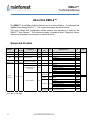
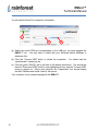
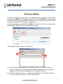
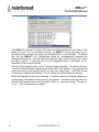
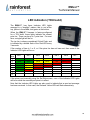
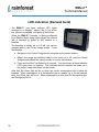
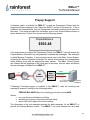
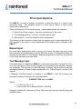
EMU-2™ Energy Monitoring Unit Technical Manual Version 1.05 Sept 2014 EMU-2™ Technical Manual Copyright © 2014 by RAINFOREST AUTOMATION, INC (“RFA”). All rights reserved. No part of this manual may be reproduced or transmitted in any from without the expressed, written permission of RFA. Under copyright law, this manual or the software described within, cannot be copied, in whole or part, without the written consent of the manufacturer, except in the normal use of the software to make a backup copy. The same proprietary and copyright notices must be affixed to any permitted copies as were affixed to the original. This exception does not allow copies to be made for others, whether or not sold, but all of the material purchased (with all backup copies) can be sold, given, or loaned to another person. Under the law, copying includes translating into another language or format. Rainforest Automation may have patents, patent applications, trademarks, copyrights, or other intellectual property rights covering subject matter in this document. Except as expressly provided in any written license agreement from Rainforest Automation, the furnishing of this document does not give you any license to these patents, trademarks, copyrights, or other intellectual property. Trademarks Third-party brands and company names mentioned herein may be trademarks and/or registered trademarks of their respective companies and are the sole property of their respective manufacturers. Notice The author(s) assumes no responsibility for any errors or omissions that may appear in this document nor does it make a commitment to update the information contained herein. 2 EMU-2™ Technical Manual EMU-2™ – Energy Monitoring Unit RFA-Z105-2 Version 1.05 Technical Manual Table of Contents Regulatory information ................................................................................................. 4 About This Manual ........................................................................................................ 5 About the EMU-2™ ........................................................................................................ 6 Supported Clusters ...................................................................................................... 6 Startup Procedure ......................................................................................................... 8 Diagnostic Mode.......................................................................................................... 10 Diagnostic Mode Navigation Flowchart...................................................................... 11 EMU-2™ Diagnostic Mode Screens .......................................................................... 12 Hard Reset....................................................................................................... 12 Device ID ......................................................................................................... 12 Link Key ........................................................................................................... 12 Device Info ....................................................................................................... 12 Hard Reset ................................................................................................................... 13 Connecting to the Serial Port ..................................................................................... 14 Firmware Update ......................................................................................................... 17 LED indication (TOU build) ......................................................................................... 19 LED indication (Demand build) .................................................................................. 20 Prepay Support ........................................................................................................... 21 Price Input Options ..................................................................................................... 23 Manual Input .............................................................................................................. 23 Text Message Input ................................................................................................... 23 Meter Input ................................................................................................................ 24 Serial Port Input ......................................................................................................... 24 3 EMU-2™ Technical Manual Regulatory information FCC Notices This device complies with part 15 of the FCC Rules. Operation is subject to the following two conditions: (1) This device may not cause harmful interference, and (2) this device must accept any interference received, including interference that may cause undesired operation. Changes or modifications not expressly approved by the manufacturer could void the user’s authority to operate the equipment. FCC/IC RF Exposure Statement This equipment complies with FCC and Industry Canada radiation exposure limits set forth for an uncontrolled environment. The antenna(s) used for this equipment must be installed to provide a separation distance of at least 8 inches (20cm) from all persons. ICES-003 Compliance This Class B digital apparatus complies with Canadian ICES-003. Note: This equipment has been tested and found to comply with the limits for a Class B digital device, pursuant to part 15 of the FCC Rules. These limits are designed to provide reasonable protection against harmful interference in a residential installation. This equipment generates, uses and can radiate radio frequency energy and, if not installed and used in accordance with the instructions, may cause harmful interference to radio communications. However, there is no guarantee that interference will not occur in a particular installation. If this equipment does cause harmful interference to radio or television reception, which can be determined by turning the equipment off and on, the user is encouraged to try to correct the interference by one or more of the following measures: Reorient or relocate the receiving antenna. Increase the separation between the equipment and receiver. Connect the equipment into an outlet on a circuit different from that to which the receiver is connected. Consult the dealer or an experienced radio/TV technician for help. Compliance Regulations For Australia and New Zealand This equipment complies with the C-Tick labeling requirements for Australia and in New Zealand. As a radio transmitter, this device complies with the requirements of AS/NZS 4268:2008 as designated in the Radiocommunications (Short Range Devices) Standard 2004 for Australia and as required by the Radiocommunications Regulations (General Users Radio License for Short Range Devices) Notice 2011 for New Zealand. This device is a Category A device as defined in the Radiocommunications (Compliance Labeling - Electromagnetic Radiation) Notice 2003. 4 EMU-2™ Technical Manual About This Manual This manual is intended for those needing detailed technical information about the EMU-2™ product, such as customer support engineers and laboratory and field engineers performing evaluations and trials involving the EMU-2™. This manual is a companion to the EMU-2™ User Manual, and both documents should be consulted. None of the information contained in this manual should be required by the average consumer to operate the EMU-2™ product under normal conditions. 5 EMU-2™ Technical Manual About the EMU-2™ The EMU-2™ is a ZigBee endpoint that acts as an In-Home Display. It implements the ZigBee Smart Energy Profile 1.1. The supported clusters are shown below. The Active Mode and Configuration Mode screens are described in detail in the EMU-2™ User Manual. This manual provides information about Diagnostic Mode, which is not intended to be used by non-technical users. Supported Clusters Cluster Cluster Client/ ID Server Commands Basic 0x0000 Server Mandatory Commands Identify 0x0003 Server Mandatory Commands Time 0x000a Client Key 0x0800 Establishment Read Attributes Client/ Mandatory Commands Server GetProfile GetProfileResponse (received) Cmd ID Attribute Set 0x0702 0x00 Meter Status 0x00 Formatting 6 Option 0x0000 0x0001 0x0007 EndTime Status ProfileIntervalPeriod NumberOfPeriodsDelivered Intervals CurrentSummationDelivered 0x00 CurrentSummationReceived CurrentBlockPeriodConsumptionDelivered 0x00 0x01 0x0c 0x02 Status 0x00 UnitofMeasure Multiplier Divisor 0x03 SummationFormatting DemandFormatting MeteringDeviceType 0x00 0x01 0x02 0x03 0x04 0x06 Historical 0x04 InstantaneousDemand Consumption …continued on next page Attribute ID 0x00 Client Read Attributes Attributes read Time TimeStatus LocalTime 0x00 Reading Information Simple Metering AttSet ID 0x00 Block Price EMU-2™ Technical Manual Cluster Cluster ID Client/ Server Commands GetCurrentPrice GetSceduledPrices PriceAcknowledgement PublishPrice (received) Price 0x0700 Cmd ID 0x00 0x0703 0x00 Block Threshold 0x01 Block Period 0x02 Commodity 0x03 Block Price Information 0x04 Billing Information Client Attributes Attributes read Attribute ID Option 0x07 Rate Label Currency Price Trailing Digit and Tier Number Of Price Tiers & Register Tier Start Time Duration Price Number Of Block Thresholds Price Control Tier1PriceLabel Tier2PriceLabel Tier3PriceLabel Tier4PriceLabel Tier5PriceLabel Tier6PriceLabel Tier7PriceLabel Block1Threshold Block2Threshold Block3Threshold Block4Threshold Block5Threshold StartOfBlockPeriod BlockPeriodDuration (minutes) ThresholdMultiplier ThresholdDivisor Standing Charge NoTierBlock1Price NoTierBlock2Price NoTierBlock3Price NoTierBlock4Price NoTierBlock5Price CurrentBillingPeriodStart CurrentBillingPeriodDuration Block Price 0x00 0x01 0x02 0x03 0x04 0x05 0x06 0x00 0x01 0x02 0x03 0x04 0x00 0x01 0x02 0x03 0x01 0x00 0x01 0x02 0x03 0x04 0x00 0x01 Price Label Block Price 0x00 0x01 0x01 Client DisplayMessage (received) Prepayment Tier Label Client GetLastMessage Message Confirmation Cancel Message (received) 0x0703 AttSet ID 0x00 0x01 0x02 Attributes Message Attribute Set 0x00 Prepayment Information Set MessageID MessageControl MessageID MessageControl StartTime Duration Message Payment Control 0x00 Credit Remaining Credit Status 0x00 0x01 0x03 only enabled for prepayment support only enabled if Price Labels are used instead of Rate Label only enabled for block pricing support Prepay Prepay Price Label Block Price 7 EMU-2™ Technical Manual Startup Procedure Once the EMU-2™ has successfully completed its initialization procedures, the display will show the Startup screen. Normally, this is the Rainforest Automation logo: Then the Joining Procedure will begin. The procedure is as follows: Send Beacon Request, and look for a device that has the 'join' flag enabled in its beacon. After joining the network, wait for the Coordinator to send the network key encrypted with our link key (derived from the install code). Look for the Key Establishment Cluster using match descriptor. Perform Key Exchange. If successful, look for the time cluster and the metering cluster. If successful, ask for time. The time needs to be a valid value. If successful, ask for metering, pricing, and messaging. The flowchart for this procedure is shown below, along with the output screens that are displayed during the procedure: 8 EMU-2™ Technical Manual For each Channel 11 up to 26 Searching f or meters Send Beacon Request Receive Beacons, make list of Candidates For each Candidate Connecting to Meter Try to Join Please Wait... Joined? Y N Key Exchange Success? Y N Get Meter Data Success? N Y Exit Next Candidate Next Channel Start Again Active Mode The Joining Procedure is repeated continuously, cycling through all the channels (1126), looking for candidates to join. It is important that the device not be restarted during the Joining Procedure. This has unpredictable results, and may cause the device to be decommissioned, as if it had performed a Hard Reset. 9 EMU-2™ Technical Manual Diagnostic Mode Diagnostic Mode provides a number of screens that give you technical details about the EMU-2™, and also provide access to advanced functions, such as Hard Reset and Firmware Update. To get into Diagnostic Mode, you must first put the EMU-2™ into Configuration Mode. This is done by pressing and releasing both buttons simultaneously (note that this should not be attempted until the EMU-2™ has successfully connected to the smart meter). Once in Configuration Mode, hold down both buttons for at least five seconds. When the buttons are released, Diagnostic Mode will be initiated. Note that the unit will automatically return to Active Mode after one minute of inactivity. 10 EMU-2™ Technical Manual Diagnostic Mode Navigation Flowchart Configuration Mode both buttons Active Mode 1 minute inactivity hold both buttons f or 5 seconds, release Sleep Mode 4 minutes inactivity 1 minute inactivity Diagnostic Mode Hard Reset screen any button Top Button Disconnect from meter Bottom Button Device ID screen any button Link Key screen any button Device info screen any button 11 EMU-2™ Technical Manual EMU-2™ Diagnostic Mode Screens Hard Reset The Hard Reset screen allows you to perform a Hard Reset by pressing the Top Button. Pressing the Bottom Button sends you to the Device ID screen. Hard Reset? Reset Skip Device ID The Device ID screen shows the Install Code (IN) and MAC Address (MAC) for this particular device. Both are 16 digit hex numbers. Pressing any button sends you to the Link Key screen. Device ID IN:ee6d785b8006db6d MAC:00158d00001a56d7 Link Key The Link Key screen shows the Preconfigured Link Key for this EMU-2™. It consists of 16 pairs of hex digits. Pressing any button sends you to the Device Info screen. Link Key 78:af:a4:da:a3:e9:0b:24 9d:15:20:0e:da:a8:74:d2 Device Info The Device Info screen shows the revision number of the firmware (FW) installed on the device, as well as the hardware version (HW) of the EMU-2™. Pressing any button sends you to Active Mode. 12 Device Info HW: 3.0.1 FW: 1.2.12 (3094) EMU-2™ Technical Manual Hard Reset A Hard Reset will erase all existing data and configurations on the EMU-2™. The device will be decommissioned and will not be able to immediately rejoin the smart meter. The smart meter will not allow the EMU-2™ to join until the meter has also decommissioned the EMU-2™, and then reregistered EMU-2™ for joining. A Hard Reset can be initiated from the Hard Reset screen in Diagnostic Mode (see the previous section, “Diagnostic Mode”). Selecting “Reset” (Top Button) in the Hard Reset screen brings up the following screen that confirms that you intend to perform a Hard Reset and disconnect from the meter: Are you sure? Disconnect from meter Cancel Pressing “Cancel” (Bottom Button) will abort the process and send you to Active Mode. Pressing the Top Button will erase all existing data and configurations, disconnect from the meter, and reset the EMU-2™. 13 EMU-2™ Technical Manual Connecting to the Serial Port You can connect your Windows computer to the EMU-2™ serial port. This will allow you to access the real time meter data directly, and will also let you program in complex pricing structures, and even update the internal firmware to enable new features. The serial port is a Mini USB port, found above the power socket on the side of the EMU-2™. You will need a cable (like those typically used for digital cameras) to connect this port on the EMU-2™ to the USB port of your Windows computer. Your computer should be running Windows 7 or greater. It must also have the .NET Framework (ver 2.0 or greater) installed. If .NET is not installed on your computer, you will be prompted to download it during the software installation procedure. Before connecting the EMU-2™ to your computer, you will need to install the Personal Meter Reader™ software. Go to the link: http://www.rainforestautomation.com/raven_support Click on the Personal Meter Reader™ link to download the software. Save the .ZIP file when prompted. Extract the files in the .ZIP folder. Double click on the application file named “setup.exe”. Note that this installation requires that you have the necessary permissions to install programs on your hard drive. You may need Power User/Admin permissions. You must agree to run the install when you are prompted to do so. You will see the Welcome screen for the Setup Wizard. Click on “Next” and follow the onscreen directions to complete the installation of the software. When the software installation is complete, there will be a new icon on your desktop that is a shortcut to the Personal Meter Reader™ software. Launch the application by double clicking on the icon. After a moment you will see the Personal Meter Reader™ window. 14 EMU-2™ Technical Manual Ensure that the EMU-2™ is powered only by its AC adapter, and there are no batteries installed; power from the batteries may interfere with operation of the USB port. Connect the device to your computer using the Mini USB cable. When the EMU-2™ is plugged in for the first time, the device drivers have to be installed. This should be done automatically by Windows. If, for some reason, Windows is unable to find the drivers, you will need to install them manually. The drivers are available for download at: http://www.rainforestautomation.com/developer. In the Personal Meter Reader™ program, click the blue button to the left of “Connection” to expand the box. 15 EMU-2™ Technical Manual You will see the Serial Port connection information. c a b (a) Select the serial COM port corresponding to the USB port you have plugged the EMU-2™ into. You may have to check with your Windows Device Manager to determine this. (b) Click the “Connect USB” button to initiate the connection. You should see the “speedometer” screen pop up. (c) Click the green “RAVEn” tab to get back to the device information. You should see that the “Disconnect USB” button is now highlighted in blue, and the “Connect USB” button is greyed out. After a few moments, the “Registration” box should display the MAC Address and Install Code for the device. Your computer is now communicating with the EMU-2™. 16 EMU-2™ Technical Manual Firmware Update A Firmware Update will replace all of the application code contained in the program memory of the EMU-2™. The update code is loaded into the EMU-2™ using the serial port and the Personal Meter Reader™ software. You will need to follow the directions in the previous section, “Connecting to the Serial Port”. Once your computer is connected to the EMU-2™, click the “Home” tab at the top of the Personal Meter Reader™ screen, and select “Firmware”. The “Firmware Update” window should pop up. b a (a) Click the button to the right of the “Firmware File” field. You should be able to browse to the .zigbee file that contains the updated code image. Once you have selected it, the file name should appear in the “Firmware File” field. (b) Click the “Check File” button. You will see several lines of info appear in the lower half of the window, ending with, “Check File complete.” 17 EMU-2™ Technical Manual If the EMU-2™ is joined to a meter, then press one of the buttons until the Current Time screen is shown. If it is not joined to a meter, the EMU-2™ will be very busy trying to find and connect; this will slow down the communication on the serial port. To prevent this, put the EMU-2™ into Configuration Mode by simultaneously pressing and releasing both buttons. This will temporarily halt the meter search activity until it times out after 1 minute. If you keep the unit in Configuration Mode, it will speed up the download of the Firmware Update. Click the “Start Update” button in the “Firmware Update” window. You will see the line, “Update Firmware Started” appear in the lower half of the window. The progress bar across the center of the window will fill over and over, many times. It will take at least 16 minutes to load the new firmware. Do not unplug the device during this process. When the download is done, the message, “Firmware download complete; switching to new firmware” will appear at the bottom of the window. The device will then be reset, and the new firmware version will be verified. When you see the message, “Firmware is x.x.xx…”, then the process is complete. 18 EMU-2™ Technical Manual LED indication (TOU build) The EMU-2™ has three Indicator LED Lights arranged in a “stoplight” pattern; that is, red at the top, yellow in the middle, and green at the bottom. When the EMU-2™ firmware is factory-configured for a TOU build, these lights indicate the current price tier. There can be up to 7 price tiers. For most tiers, a single light will be on. The top tier is always considered Critical Peak, and is indicated by a double flash of the Red LED every 3 seconds. If the number of tiers is 1 or 0, or if the price tier has not been set, then none of the Indicator LED Lights will be on. # of tiers 7 6 5 4 3 2 1 0 tier 1 tier 2 tier 3 tier 4 tier 5 tier 6 tier 7 green green green green green green green green yellow yellow yellow flashing red yellow yellow red red flashing red yellow yellow red flashing red red red flashing red red flashing red flashing red If the price is set manually using the Set Rate screen, none of the Indicator LED Lights will be on while the manually set price is in effect. Note that the Indicator LED Lights are also used to indicate that a new text message has been received. In that case, the Red and Yellow LEDs will flash alternatively. 19 EMU-2™ Technical Manual LED indication (Demand build) The EMU-2™ has three Indicator LED Lights arranged in a “stoplight” pattern; that is, red at the top, yellow in the middle, and green at the bottom. When the EMU-2™ firmware is factory-configured for a Demand build, these lights indicate the current rate of demand for power (in kW) relative to a baseline. The baseline is initially set to 0.5 kW, but can be changed while in the Current Usage screen. To set the baseline: Navigate to the Current Usage screen using the device control buttons. Adjust your usage by switching loads in your house on or off, until the Current Usage screen shows the value you want to use for the baseline. Press and hold the Top Button for 5 seconds. You should see all three Indicator LED Lights come on together. This indicates that the baseline has been set to the current usage rate shown on the screen. After that, the Green light will be on when the current consumption rate is below the baseline. When consumption is at the baseline rate or greater (up to 5x the baseline rate), the Yellow light will be on. When consumption is more than 5x the baseline rate, the Red light will be on. 20 EMU-2™ Technical Manual Prepay Support A firmware option is available for EMU-2™ to read the Prepayment Cluster (see the Supported Clusters diagram in the “About the EMU-2” section in this manual). If this is enabled in the firmware build, then the Prepayment Information attribute set is read from the meter. If the meter provides this information, then a new Prepaid Balance screen is shown between the Current Price screen and the Message screen: Prepaid Balance $503.48 If the meter does not support the Prepayment Cluster, the EMU-2™ can still receive the Prepaid Balance information by using specially formatted text messages. This technique is called Message Tunneling. A text message can be sent to the Meter Control System, containing the account balance information, as well as a time stamp and corresponding meter reading, along with the appropriate meter number. The Meter Control System can forward the text message in the usual way to the meter, and the meter will deliver the text message via ZigBee to the EMU-2™. Meter # Text Message EMU-2™ AMI Network Meter Control System Text Message Smart Meter Account Balance Meter Reading Customer Database If Message Tunneling support is enabled in the EMU-2™, then the incoming text message is scanned, looking for the following pattern: PREPAID BALANCE= $xxx.xx (mm/dd/yyyy-hh:mm:ss) zzzzzkWh Where: xxx.xx is the account balance in dollars mm/dd/yyyy-hh:mm:ss is the date and time stamp zzzzz is the last 5 digits of the meter reading The information in the text message provides the data necessary for the EMU-2™ to provide the Prepaid Balance screen. The EMU-2™ can even estimate the up-to-date 21 EMU-2™ Technical Manual instantaneous balance between text message updates by calculating the difference in the meter reading from the last update, multiplying it by the effective price, and subtracting this from the last update balance. 22 EMU-2™ Technical Manual Price Input Options The EMU-2™ provides a number of methods to allow the input of a value for the commodity Price. This flexibility allows it to work with a variety of smart meter deployment configurations. There is a hierarchy of Price input methods. Listed highest priority first, they are: 1) Meter Price Cluster support – this input overrides any of the others. 2) Text Message parsing – this input overrides manual input. 3) Manual input – this is the default for most deployments. This hierarchy makes it easy to migrate from the simplest type of meter deployment (no Price support in the meter) to more sophisticated Price options with no changes to the EMU-2™. Manual Input For smart meter deployments with no pricing in the meter, the users can simply enter the commodity price themselves using the Set Rate screen in Configuration Mode, as described in the EMU-2™ User Manual. Besides being prone to user error, this method is only really practical for flat rate tariffs. Text Message Input A firmware option is available for EMU-2™ to allow the commodity Price and Price Tier to be set (simulating a Price Cluster PublishPrice Command) using specially formatted text messages. This technique is called Message Tunneling, and is much the same as alternative method for Prepay support mentioned in the “Prepay Support” section of this manual. If Message Tunneling support is enabled in the EMU-2™, then the incoming text message is scanned, looking for the following pattern CURRENT TIER y=$x.xxxx/kWh Where: y is the Price Tier (1-5) x.xxxx is the Price in dollars ($0.0000 - $9.9999) Using this method will overwrite any Price value that has been set manually using the Set Rate screen. 23 EMU-2™ Technical Manual This method is particularly useful for implementing dynamic and/or tiered pricing in deployments where the price cluster has not been enabled in the meters. Note that this feature is only available as a special factory option. Meter Input The EMU-2™ issues a GetCurrentPrice command to the meter every 2 minutes. If the meter responds with a PublishPrice Command with pricing information, this new Price value will override any value that has been input manually or via text message. This makes migration to full in-meter pricing transparent and painless. Serial Port Input In addition to the three techniques listed above, pricing information can also be programmed into the EMU-2™ through the USB serial port. This allows complex block pricing schemes, with up to four tiers and programmable block thresholds to be downloaded to the unit. The details of how to use this feature can be found in a separate document: the EMU-2™ Block Pricing Programming Guide. 24