1
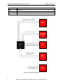
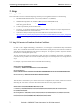
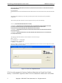
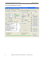
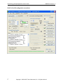
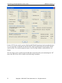
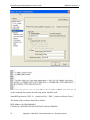
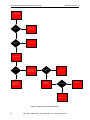
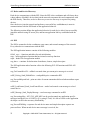
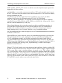
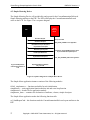
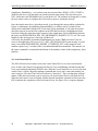
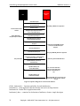
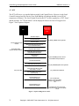
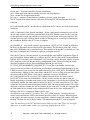
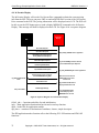
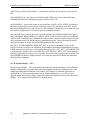
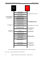
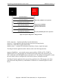
Smart Energy Sample Application User’s Guide Document Number: SWRU215 Texas Instruments, Inc. San Diego, California USA Copyright 2009-2010 Texas Instruments, Inc. All rights reserved. Smart Energy Sample Application User's Guide Revision 1.0 i SWRU215 Version 1.3 Description Initial release. Date 04/06/2009 1.1 Updated for Z-Stack 2.3 release. Document modifications include INTER-PAN support for ESP and IPD, use of End Device Annce message to trigger device discovery instead of Match Descriptor Request. 12/23/2009 1.2 Updated for Z-stack 2.3.1 release. Document modifications include support for installing Certicom keys in the CC2530 lock bits flash page and MSP430 information memory segments. The APP_MSG command is no longer used to retrieve the established link key. Instead, ZDO_GET_LINK_KEY is used. 07/29/2010 1.3 Added “In Premise Display – End Device – OTA” configuration which provides a sample OTA client application. Changed router and end device startup behavior to initiate a match descriptor request to discover the key establishment endpoint instead of assuming a fixed endpoint number. 11/16/2010 Copyright 2009-2010 Texas Instruments, Inc. All rights reserved. Smart Energy Sample Application User's Guide SWRU215 Version 1.3 Table of Contents 1. INTRODUCTION................................................................................................................. 1 1.1. 1.2. 2. SETUP.................................................................................................................................... 3 2.1. 2.2. 2.3. 3. REQUIRED TOOLS ............................................................................................................ 3 USING Z-CONVERTER TO TRANSFORM CERTICOM CERTIFICATES ................................... 3 SUPPORTED HARDWARE PLATFORMS .............................................................................. 5 GETTING STARTED .......................................................................................................... 5 3.1. 3.2. 3.3. 3.4. 4. SCOPE .............................................................................................................................. 1 DEFINITIONS, ABBREVIATIONS, ACRONYMS .................................................................... 1 BUILDING THE ESP, PCT, AND IPD APPLICATION INSTANCES ........................................ 5 CONFIGURING CERTICOM KEYS USING Z-TOOL .............................................................. 8 CONFIGURING CERTICOM KEYS FOR PRODUCTION DEVICES ......................................... 13 RUNNING THE ESP, PCT, AND IPD APPLICATIONS ........................................................ 20 THEORY OF OPERATION ............................................................................................. 23 4.1. SE SECURE JOINING ....................................................................................................... 23 4.2. KEY ESTABLISHMENT .................................................................................................... 23 4.3. DEVICE AND SERVICE DISCOVERY ................................................................................. 25 4.4. ESP................................................................................................................................ 25 4.5. SIMPLE METERING DEVICE ............................................................................................ 27 4.6. LOAD CONTROL DEVICE ................................................................................................ 28 4.7. PCT ............................................................................................................................... 31 4.8. IN PREMISE DISPLAY ..................................................................................................... 33 4.9. IN PREMISE DISPLAY – OTA.......................................................................................... 34 4.10. RANGE EXTENDER ..................................................................................................... 36 5. LIMITATIONS ................................................................................................................... 38 5.1. 5.2. 5.3. 5.4. 5.5. 5.6. 5.7. 6. APPLICABLE DOCUMENTS.......................................................................................... 39 6.1. 6.2. ii TRUST CENTER OPERATION ........................................................................................... 38 NETWORK MANAGER OPERATION ................................................................................. 38 SECURE JOINING OPERATION ......................................................................................... 38 KEY ESTABLISHMENT OPERATION ................................................................................. 38 DEVICE STARTUP BEHAVIOR ......................................................................................... 38 LOAD CONTROL DEVICE BEHAVIOR .............................................................................. 39 ESP BEHAVIOR .............................................................................................................. 39 Z-STACK DOCUMENTS (PART OF THE Z-STACK INSTALLER) .......................................... 39 OTHER DOCUMENTS (WWW.ZIGBEE.ORG)...................................................................... 39 Copyright 2009-2010 Texas Instruments, Inc. All rights reserved. Smart Energy Sample Application User's Guide SWRU215 Version 1.3 Table of Figures FIGURE 1. SYSTEM CONTEXT DIAGRAM ........................................................................................................................2 FIGURE 2. Z-CONVERTER GRAPHICAL INTERFACE .........................................................................................................4 FIGURE 3. MEMORY MAP OF LOCK BITS PAGE ...............................................................................................................13 FIGURE 4. FLOWCHART OF DEVICE STARTUP LOGIC ....................................................................................................24 FIGURE 5. SEQUENCE DIAGRAM FOR A SIMPLE METER DEVICE ...................................................................................27 FIGURE 6. SEQUENCE DIAGRAM FOR A LOAD CONTROL DEVICE .................................................................................29 FIGURE 7. SEQUENCE DIAGRAM FOR A PCT.................................................................................................................31 FIGURE 8. SEQUENCE DIAGRAM FOR AN IN PREMISE DISPLAY .....................................................................................33 FIGURE 9. SEQUENCE DIAGRAM FOR AN IN PREMISE DISPLAY WITH OTA CLUSTER CLIENT SUPPORT .........................35 FIGURE 10. SEQUENCE DIAGRAM FOR A RANGE EXTENDER .........................................................................................37 iii Copyright 2009-2010 Texas Instruments, Inc. All rights reserved. Smart Energy Sample Application User's Guide SWRU215 Version 1.3 1. Introduction ZigBee Smart Energy (ZSE) is one of the public application profiles released for the ZigBee 2007 specification. It enables utility companies and their customers to directly communicate with thermostats and other smart appliances; see www.zigbee.org for more information. The Smart Energy Sample application (part of the Z-Stack installer for ZigBee 2007; covering ZigBee and ZigBee PRO) is the optimal starting point to build your own SE application on top of Texas Instruments’ Z-Stack (www.ti.com/z-stack). 1.1. Scope This document describes how to use the Smart Energy Sample Application and discusses its theory of operation. For a more general description of Smart Energy, the reader is referred to the Zigbee Smart Energy specification available from www.zigbee.org. The reader should also review the Z-Stack Smart Energy Developer’s Guide prior to using this document. There are seven defined application instances within the IAR project: a. Energy Service Portal (ESP) as a Coordinator b. Metering Device as a Router and also as an End Device c. In Premise Display as an End Device d. In Premise Display as an End Device with OTA cluster client support e. Programmable Communicating Thermostat (PCT) as an End Device f. Load Control Device as a Router g. Range Extender as a Router Figure 1 shows the usage model of how these sample application instances interact with the ESP. 1.2. Definitions, Abbreviations, Acronyms 1 Term Definition AF Application Framework CBKE Certificate-based Key Establishment DCO Digitally Controlled Oscillator DUT Device Under Test ECC Elliptic Curve Cryptography ESP Energy Service Portal. An alternate name is Energy Service Interface (ESI) HAN Home Area Network IPD In Premise Display OSAL Operating System Abstraction Layer OTA Over The Air firmware upgrade Copyright 2009-2010 Texas Instruments, Inc. All rights reserved. Smart Energy Sample Application User's Guide PCT Programmable Communicating Thermostat SE Smart Energy ZCL ZigBee Cluster Library ZDO Zigbee Device Object SWRU215 Version 1.3 In Premise Display Queries For Latest Pricing Info, and displays MESSAGE command from ESP In Premise Display ESP Sends PCT Load Control Event Programmable Communicating Thermostat (PCT) ESP Sends Load Control Event Load Control Device ESP Simple Metering Device Reports Current Summation Delivered Attribute Periodically Range Extender will join the network, perform key establishment, and route packets but won't exchange app data with the ESP Simple Metering Device Range Extender Figure 1. System Context Diagram 2 Copyright 2009-2010 Texas Instruments, Inc. All rights reserved. Smart Energy Sample Application User's Guide SWRU215 Version 1.3 2. Setup 2.1. Required Tools The tools that will be needed to evaluate this sample app and build your own application based on it are the following: a. IAR Embedded Workbench EW8051 7.60 (CC2530) or EW430 5.10.6 (MSP430) b. SmartRF Flash Programmer Tool (includes USB drivers for the SmartRF05EB board) c. Ubiqua Protocol Analyzer from Ubilogix (www.ubilogix.com) or other type of network analyzer that can support Smart Energy profile decodes d. Z-Tool 2.0 (provided as part of the Z-Stack install) e. Z-Converter – A tool used to transform Certicom certificates data into arrays that can easily be imported into a ZTool script (Provided as part of the Z-Stack install) f. Certicom ECC library if using security. Fill out their SDK license registration form at this URL: http://www.certicom.com/index.php/component/chronocontact/?chronoformname=certicom_zigbee_sdk_registrati on_form. Alternatively, you may contact TI directly to obtain a special installer that has the Certicom ECC library included. 2.2. Using Z-Converter to Transform Certicom Certificates In order to build a ZigBee Smart Energy certified device, one must support Certificate Based Key Establishment (CBKE). CBKE requires the use of an ECC library from Certicom and a method to install certificate data into the device. One of the methods used to install Certicom certificate data is by using Z-Tool, a PC tool that can communicate with the device using the Monitor and Test API over a UART port. Test scripts are provided to inject test certificates into the device for development purposes only. The test certificate data comes in a format that a Z-Tool script does not understand, and therefore a tool called ZConverter has been provided to take Certicom certificate data as input (the actual input requires no carriage returns in order for Z-Converter to process the data correctly), and then generate arrays that can copied and pasted into a Z-Tool script. For example, a typical test certificate from Certicom looks like the following: IEEE Address: 00124b0000000001 CA Pub Key: 0200fde8a7f3d1084224962a4e7c54e69ac3f04da6b8 Device Implicit Cert: 0204ac2c2656f1eea4ff5dac4edda176bfe4fa70d95600124b0000000001544553545345434101090001000001091003 Device Private Key: 00f035a9f731f265530ad5c1202562d56d1b822543 Device Public Key: 0202f71c27abfd28eb39e0b4a718ace4cf374559a6f6 This data must be entered line by line as shown above with no carriage returns into a text file, and the user inputs this data using the “Load” button. Z-Converter then transforms this data into an array output as follows: IEEE Address: 0x01,0x00,0x00,0x00,0x00,0x4b,0x12,0x00 CA Pub Key: 0x02,0x00,0xfd,0xe8,0xa7,0xf3,0xd1,0x08,0x42,0x24,0x96,0x2a,0x4e,0x7c,0x54,0xe6,0x9a, 0xc3,0xf0,0x4d,0xa6,0xb8 Device Implicit Cert: 0x02,0x04,0xac,0x2c,0x26,0x56,0xf1,0xee,0xa4,0xff,0x5d,0xac,0x4e,0xdd,0xa1,0x76,0xbf, 0xe4,0xfa,0x70,0xd9,0x56,0x00,0x12,0x4b,0x00,0x00,0x00,0x00,0x01,0x54,0x45,0x53,0x54, 0x53,0x45,0x43,0x41,0x01,0x09,0x00,0x01,0x00,0x00,0x01,0x09,0x10,0x03 3 Copyright 2009-2010 Texas Instruments, Inc. All rights reserved. Smart Energy Sample Application User's Guide SWRU215 Version 1.3 Device Private Key: 0x00,0xf0,0x35,0xa9,0xf7,0x31,0xf2,0x65,0x53,0x0a,0xd5,0xc1,0x20,0x25,0x62,0xd5,0x6d, 0x1b,0x82,0x25,0x43 Device Public Key: 0x02,0x02,0xf7,0x1c,0x27,0xab,0xfd,0x28,0xeb,0x39,0xe0,0xb4,0xa7,0x18,0xac,0xe4,0xcf,0x37,0x45,0x59,0xa6,0xf 6 Note that the Device Public Key is not used as part of the input into the Certicom library but is provided for completeness. The user then copies these values into a Z-Tool script that uses arrays such as the following: var ieee = [0x01,0x00,0x00,0x00,0x00,0x4b,0x12,0x00]; var data0x69 = [0x02,0x04,0xac,0x2c,0x26,0x56,0xf1,0xee,0xa4,0xff,0x5d,0xac,0x4e,0xdd,0xa1,0x76,0xbf, 0xe4,0xfa,0x70,0xd9,0x56,0x00,0x12,0x4b,0x00,0x00,0x00,0x00,0x01,0x54,0x45,0x53,0x54, 0x53,0x45,0x43,0x41,0x01,0x09,0x00,0x01,0x00,0x00,0x01,0x09,0x10,0x03]; var data0x6a = [0x00,0xf0,0x35,0xa9,0xf7,0x31,0xf2,0x65,0x53,0x0a,0xd5,0xc1,0x20,0x25,0x62,0xd5,0x6d, 0x1b,0x82,0x25,0x43]; var data0x6b = [0x02,0x00,0xfd,0xe8,0xa7,0xf3,0xd1,0x08,0x42,0x24,0x96,0x2a,0x4e,0x7c,0x54,0xe6,0x9a, 0xc3,0xf0,0x4d,0xa6,0xb8]; The mapping of the labels from the Certicom certificate to the Z-Tool script is: IEEE -> var ieee Device Implicit Cert -> var data 0x69 Device Private Key -> var data 0x6a CA Pub Key -> var data0x6b Figure 2 provides a screenshot of the Z-Converter graphical interface. The user can also save the output into a text file for later use using the “Save As” button. Figure 2. Z-Converter Graphical Interface Z-Tool is used to program the Certicom Certificate information into Z-stack Non-Volatile memory. A serial cable is required to allow Z-Tool to communicate with the stack via the DB-9 4 Copyright 2009-2010 Texas Instruments, Inc. All rights reserved. Smart Energy Sample Application User's Guide SWRU215 Version 1.3 connector on the SmartRF05EB board. The MSP5438 Experimenter’s board uses the mini-USB connector with the supported virtual COM port driver available from the TI website. 2.3. Supported Hardware Platforms a. SmartRF05EB/BB boards with CC2530EM b. SmartRF05EB boards with CCMSP2618 + CC2520EM c. MSP5438 Experimenter boards with CC2520EM 3. Getting Started 3.1. Building the ESP, PCT, and IPD Application Instances The Smart Energy sample application project is located in C:\Texas Instruments\ZStack-2.4.01.4.0\Projects\zstack\SE\SampleApp\<Target> (e.g. <Target> = CC2530DB). Open the SampleApp.eww project file. The figures below show how each configuration is organized. For each device configuration, only the relevant application files are brought in for each device configuration. 5 Copyright 2009-2010 Texas Instruments, Inc. All rights reserved. Smart Energy Sample Application User's Guide SWRU215 Version 1.3 Build the “ESP – Coordinator”, “PCT – End Device”, and “In Premise Display – End Device” configurations. 1. If the SECURE=1 compile option is used, before rebuilding the project, take the Certicom library and rename it to ecc.r51 (for 8051 builds) or ecc.r43 (for MSP430 builds) and drop it into C:\Texas Instruments\ZStack-2.4.01.4.0\Projects\zstack\Libraries\<Target>\bin (e.g. <Target> = CC2530DB). 2. The NWK_INDIRECT_MSG_TIMEOUT parameter in the f8wConfig.cfg file must be increased to a suggested value of 10 in order to buffer the message long enough to accommodate the 8 second poll period by the end device. The MAX_POLL_FAILURE_RETRIES parameter should also be set to 4 as during the CBKE procedure the ESP will be somewhat unresponsive to data requests during this time. 3. To gain access to the link key that is established via CBKE using Z-Tool, the compile options MT_ZDO_FUNC and MT_SYS_KEY_MANAGEMENT must be defined. For production, it is not recommended to turn on the MT_SYS_KEY_MANAGEMENT compile option so that the established link key cannot be read via the serial port. 4. Select Project -> Rebuild All. 6 Copyright 2009-2010 Texas Instruments, Inc. All rights reserved. Smart Energy Sample Application User's Guide SWRU215 Version 1.3 5. Highlight the configuration desired and go to Project -> Options and select the “Erase flash” option as shown for the CC2530 project. This allows one to start with a clean slate before programming Certicom certs. After the device has been configured, unselect this box so you can retain the IEEE address and key information when downloading new code each time. For MSP5438 projects, select “Erase main and information memory” as shown below. IMPORTANT NOTE: For MSP430 users that have ADC calibration info stored in INFOA information memory (such as MSP430F2618 users), DO NOT select this option unless you are sure that the INFOA information memory segment is locked. Otherwise you will erase the ADC calibration info and DCO constants and may have to restore it. From the factory, the INFO information memory segment is typically locked, so unless the user has unlocked this segment, there is no danger of overwriting this region of information memory. 7 Copyright 2009-2010 Texas Instruments, Inc. All rights reserved. Smart Energy Sample Application User's Guide SWRU215 Version 1.3 6. Download the program by clicking on the debug icon or by going to Project -> Debug. Hit the Run button, and watch the coordinator start up, or if it’s a device, it will blink its LED waiting for you to press SW1 to join an existing network. 3.2. Configuring Certicom Keys Using Z-Tool In order to configure the IEEE address and Certicom keys for each device, use the provided Z-Tools scripts and Z-Tool as shown in the following screen captures: 8 Copyright 2009-2010 Texas Instruments, Inc. All rights reserved. Smart Energy Sample Application User's Guide SWRU215 Version 1.3 Open Z-Tool from the Texas Instruments start menu links and select Tools -> Settings to configure the baud rate, Port Alias, and Handshake protocol as shown above. It is crucial that the Port Alias matches what is used in the script. Then as shown in the figure below, go to the Settings -> Scripts tab to import the scripts. Point it to the folder where the scripts are located by clicking on add. There are already pre-made Z-Tool scripts which you can use in the folder "Z-Tool scripts" in ZStack-2.4.0-1.4.0\Tools\Z-Converter. There is one for each type of device, coordinator, router, and end device. Coordinator = IEEE address ending with 01 (Port Alias = “C”) Router = IEEE address ending with 02 (Port Alias = “R”) End Device = IEEE address ending with 03 (Port Alias = “E”) Of course, there is no reason that you couldn't interchangeably use the scripts, but using it in this order makes it easier to keep track of configuration of certs. 9 Copyright 2009-2010 Texas Instruments, Inc. All rights reserved. Smart Energy Sample Application User's Guide SWRU215 Version 1.3 Then, go to Tools -> Script Control and execute the script called “writeC-all Keys.zjs” by highlighting it and clicking on the RUN button. 10 Copyright 2009-2010 Texas Instruments, Inc. All rights reserved. Smart Energy Sample Application User's Guide SWRU215 Version 1.3 Repeat this procedure for each device you wish to configure with the IEEE address and certificate data. Note: For the CC2530 platform, if Z-Tool is not used to populate the IEEE address and certificate data, then the pre-defined data in zcl_cert_data.c will be used to initialize the corresponding NV items. This is the out-of-box behavior that is enabled via the TC_LINKKEY_JOIN compile option. Once key establishment is successful, use the ZDO_GET_LINK_KEY command to extract the link key established for the device. This can be run on any of the pair of devices in order to get the key (needed for the packet sniffer as described below). Configure the ZDO_GET_LINK_KEY command as shown below. The only value that changes is the IEEEAddress of the partner device. 11 Copyright 2009-2010 Texas Instruments, Inc. All rights reserved. Smart Energy Sample Application User's Guide SWRU215 Version 1.3 Enter the correct partner IEEE address here In order to decode APS secured packets in Ubiqua, one must enter in this key. The best way to format this key is to copy and paste it into notepad, and just replace “0x” with blank space, then “,” with blank space. If the link key extraction is not successful, the string of bytes (16 total) will not be displayed. Copy and paste the key into Ubiqua: 12 Copyright 2009-2010 Texas Instruments, Inc. All rights reserved. Smart Energy Sample Application User's Guide SWRU215 Version 1.3 3.3. Configuring Certicom Keys for Production Devices Section 3.2 discussed a method for configuring Certicom keys. This works well for the development phase, but for production, a different solution is often desired to help streamline the manufacturing process. For this reason, and also for enhanced security, Z-stack provides an option to store the Certicom keys in the lock bits page of the CC2530 and information memory of the MSP430. This is also the recommended option as each family of chips has a locking mechanism to prevent direct access of code space from their respective debug ports (such as JTAG). On the CC2530, the last available page of flash is used. Figure 3 shows the memory map of the lock bits page. Byte 2048 Lock Bit Bytes (16 bytes) OSAL Application Secondary IEEE (8 bytes) Device Private Key (21 bytes + 1 byte padding to NV word size) CA Public Key (22 bytes) Implicit Cert (48 bytes) CC2530 flash memory map Page 127 Reserved for future Z‐stack use (1932 bytes) Byte 0 Lock bits page Pages 1‐126 Page 0 Figure 3. Memory map of lock bits page On the 54xx, the following locations in the info memory are used: // The INFOA page: // RESERVED for future Z-Stack use: #define HAL_NV_DEVICE_PRIVATE_KEY_ADDR #define HAL_NV_CA_PUBLIC_KEY_ADDR #define HAL_NV_IMPLICIT_CERTIFICATE_ADDR #define HAL_NV_IEEE_ADDR 13 0x1980 - 0x199c 0x199D 0x19B2 0x19C8 0x19F8 Copyright 2009-2010 Texas Instruments, Inc. All rights reserved. Smart Energy Sample Application User's Guide SWRU215 Version 1.3 For the 2618, the following locations in the info memory are used: #define HAL_NV_IEEE_ADDR #define HAL_NV_IMPLICIT_CERTIFICATE_ADDR #define HAL_NV_CA_PUBLIC_KEY_ADDR #define HAL_NV_DEVICE_PRIVATE_KEY_ADDR // RESERVED for future Z-Stack use: // MSP Calibration Data (ADC/DCO): 0x1000 0x1008 0x1038 0x104E 0x1063 - 0x10D9 0x10DA - 0x10FF Populating the Certicom key data in the MSP430 info memory can be done via a 3rd party programmer tool like the FET-Pro430 from Elprotronic Inc (www.elprotronic.com). Consult section 6.1 of the FET-Pro430 user manual for more details on how to generate a code file to update the corresponding sections of info memory only. The following sections below provide example code files and screenshots of the FET-Pro430 setup for the 2618 and 54xx devices. IMPORTANT NOTE: For best results, one should download the program first using IAR (ensuring to erash flash), then run the FET-Pro430 to update the various information memory segments. This is because when Z-stack first starts up, NV items are created and populated with the values read from the information memory segments. 54xx Fet-Pro430 sample code file @19F8 01 00 00 00 00 4b 12 00 @19C8 03 07 8c 45 de a5 06 d0 7f 1b 82 21 22 b5 a3 1e b0 a0 d6 29 55 db 00 12 4b 00 00 00 00 01 54 45 53 54 53 45 43 41 01 09 00 08 00 00 00 00 00 00 @19B2 02 00 fd e8 a7 f3 d1 08 42 24 96 2a 4e 7c 54 e6 9a c3 f0 4d a6 b8 @199D 02 28 4a 56 3f 02 f2 c8 bd a7 57 f9 61 bb 8c b4 fb 6e 90 ed 42 q 14 Copyright 2009-2010 Texas Instruments, Inc. All rights reserved. Smart Energy Sample Application User's Guide SWRU215 Version 1.3 54xx Fet-Pro430 configuration screenshots 15 Copyright 2009-2010 Texas Instruments, Inc. All rights reserved. Smart Energy Sample Application User's Guide SWRU215 Version 1.3 2618 Fet-Pro430 sample code file @1000 01 00 00 00 00 4b 12 00 @1008 03 07 8c 45 de a5 06 d0 7f 1b 82 21 22 b5 a3 1e b0 a0 d6 29 55 db 00 12 4b 00 00 00 00 01 54 45 53 54 53 45 43 41 01 09 00 08 00 00 00 00 00 00 @1038 02 00 fd e8 a7 f3 d1 08 42 24 96 2a 4e 7c 54 e6 9a c3 f0 4d a6 b8 @104E 02 28 4a 56 3f 02 f2 c8 bd a7 57 f9 61 bb 8c b4 fb 6e 90 ed 42 q 16 Copyright 2009-2010 Texas Instruments, Inc. All rights reserved. Smart Energy Sample Application User's Guide SWRU215 Version 1.3 2618 Fet-Pro430 configuration screenshots 17 Copyright 2009-2010 Texas Instruments, Inc. All rights reserved. Smart Energy Sample Application User's Guide SWRU215 Version 1.3 For the CC2530, the console version of the SmartRF Flash Programmer has been updated (since ver 1.8) to provide a command line interface that is able to program the lock bits page with the certificate data. The console program accepts a .hex file along with the certificate data in .txt format. The .hex image can be created using the IAR linker output tab and by un-commenting the “-M” lines in the f8w2530.xcl file as shown in the following screenshots. 18 Copyright 2009-2010 Texas Instruments, Inc. All rights reserved. Smart Energy Sample Application User's Guide SWRU215 Version 1.3 At the command line prompt, the following syntax should be used: SmartRFProgConsole S EPV “F= <path to hex file>” EKF=”<path to certificate file.txt>” The format of the certificate should be as follows: IEEE Address: 00124b0000000003 CA Pub Key: 0200fde8a7f3d1084224962a4e7c54e69ac3f04da6b8 19 Copyright 2009-2010 Texas Instruments, Inc. All rights reserved. Smart Energy Sample Application User's Guide SWRU215 Version 1.3 Device Implicit Cert: 0204ac2c2656f1eea4ff5dac4edda176bfe4fa70d95600124b0000000003544553545345434101090 001000001091003 Device Private Key: 034bc37a7210b7407a51dc11e5aebaf2e1503f6955 Device Public Key: 020718021c2ce9c58d2ad8352ab9ff452ff1c3bdadb3 Note: The data for the device implicit cert should be on one line (i.e. no carriage return separations should be included). The .hex image would then be programmed into the CC2530 using the SmartRF Flash Programmer tool at the same time the lock bits page is programmed with the certificate data in the .txt file. The screenshot below shows an example. There are also several functions in the console version that can be used to create a very flexible script. First, note the 'x' option, that will list all available EBs. Example: C:\Program Files\Texas Instruments\SmartRF Flash Programmer>SmartRFProgConsole.exe x Texas Instruments SmartRF Flash Programmer -----------------------------------------Device:SmartRF05EB ID:2769 (fwId:0500, fwRev:0013) Chip:CC2530 Device:SmartRF05EB ID:7335 (fwId:0500, fwRev:0013) Chip:CC2530 One can then write a batch script (or similar) with the following lines: SmartRFProgConsole.exe S(2769) EPV F="hex_image.hex" EKF="certificate_data_1.txt" SmartRFProgConsole.exe S(7335) EPV F="hex_image.hex" EKF="certificate_data_2.txt" This example assumes that the path of the .hex image and the certificate data .txt file are in the same directory as the SmartRFProgConsole.exe. 3.4. Running the ESP, PCT, and IPD Applications After compiling these sample app instances and programming the devices one can start these applications as follows: 1. Power the coordinator, wait for "Zigbee Coord" to show up on the LCD display. The 2nd line of the LCD will display the PAN ID. 20 Copyright 2009-2010 Texas Instruments, Inc. All rights reserved. Smart Energy Sample Application User's Guide SWRU215 Version 1.3 2. Then power the PCT device. The LED will flash, waiting for you to press SW1 which is joystick UP. This will cause the device to join the network. Wait about 20 seconds for the key establishment procedure to complete. Verify with the sniffer that the end device received the confirm key response. Then, press SW2 (joystick to the right) to send a PCT event to the PCT device. The PCT device will flash its LED and display "PCT Evt Started". When it completes the PCT event (which is for 1 min), then it will stop flashing its LED and display "PCT Evt Complete". 3. Power up the IPD end device. Hit SW1 to let it join the network. Wait about 20 seconds for the key establishment procedure to complete. Verify with the sniffer that the end device received the confirm key response. Then, every 5 seconds it will get the pricing info and display the provider id. On the coord, hit SW3 (joystick down) to send a display message to the IPD. "Rcvd MESSAGE Cmd" should be displayed. The Get Current Price command can also be sent from the IPD via INTER-PAN by press SW2 on the IPD. Note: NV_RESTORE is not turned on by default, so if you power cycle any of the devices, it needs to go through the key establishment procedure again, and a different link key would be used. NV_RESTORE is turned off by default to allow rapid development. Also, any device joining the ESP wouldn't be able to join more than once since the new link key is used for authenticating the device instead of the default TC link key. Power cycle the ESP and then the joining device so that it is able to join using the default TC link key. The following shows what happens in the Ubiqua Protocol Analyzer for these application instances. 21 Copyright 2009-2010 Texas Instruments, Inc. All rights reserved. Smart Energy Sample Application User's Guide 22 SWRU215 Version 1.3 Copyright 2009-2010 Texas Instruments, Inc. All rights reserved. Smart Energy Sample Application User's Guide SWRU215 Version 1.3 4. Theory of Operation This section explains how each application instance behaves with respect to the ESP device and also discusses the design of each application instance. 4.1. SE Secure Joining The default trust center link key (TC link key) is used to commission each device. Each device uses the SE secure joining process. See the Z-stack Smart Energy Developer’s Guide for more details. 4.2. Key Establishment Upon successfully joining the network using security, each device will initiate key establishment with the ESP. Certificate information required to perform the key establishment is entered in ahead of time using Z-Tool. Figure 4 shows a flowchart of the device startup logic. The ZDO_STATE_CHANGE event is an OSAL system message that is provided to the application to indicate that the device has successfully started or joined the network. 23 Copyright 2009-2010 Texas Instruments, Inc. All rights reserved. Smart Energy Sample Application User's Guide SWRU215 Version 1.3 ZDO_STATE_CHANGE Event SECURE = 1? NO Set POLL_RATE to 8 seconds, Start Application Function YES Is Router/End Device? NO Do Nothing YES Check Link Key Status Link Key Exists? YES Set POLL_RATE to 8 seconds, Start Application Function NO Initiate Match Descriptor Request for Key Establishment Endpoint Match Desc Rsp Rcvd? NO Do Nothing YES Initiate Key Establishment Key Established? YES Start Application Function Figure 4. Flowchart of Device Startup Logic 24 Copyright 2009-2010 Texas Instruments, Inc. All rights reserved. NO Do Nothing Smart Energy Sample Application User's Guide SWRU215 Version 1.3 4.3. Device and Service Discovery Each device communicates with the ESP. Since the ESP is the coordinator and will always have a short address of 0x0000, devices that join the network can assume this and communicate with the ESP directly. Therefore, no device discovery or service discovery is required for joining devices. Once the device joins the network and performs a successful key establishment, it starts its communications with the ESP based on the application behavior. The following section defines the application behavior for each device after it has successfully joined the network using SE secure join, and has an application link key established with the ESP. 4.4. ESP The ESP is assumed to be the coordinator, trust center, and network manager of the network. Every other device communicates with the ESP. The ESP application instance consists of the following modules: OSAL_esp.c - functions and tables for task initialization esp.c – main application function that has init and event loop function esp.h – header file for application module esp_data.c – container for declaration of attributes, clusters, simple descriptor The ESP application makes function calls to the following ZCL SE functions and ZDO API functions: esp_GetCurrentPriceCB – callback executed when get current price message is received zclSE_Pricing_Send_PublishPrice – send publish price command to IPD esp_ProcessInReportCmd - print out value of current summation delivered when attribute report is received zclSE_LoadControl_Send_LoadControlEvent – send a load control event message to a load control device zclSE_Message_Send_DisplayMessage – send a message command to an IPD esp_ProcessAppMsg – MT_SYS_APP_MSG can be used to tunnel any application specific messages into the device via UART (e.g. by using Z-Tool). It is left as a hook so the application developer can fill in the necessary functionality. esp_ProcessZDOMsg – responses for end device annce and simple descriptor requests are processed here. When an end device annce message is received, the 25 Copyright 2009-2010 Texas Instruments, Inc. All rights reserved. Smart Energy Sample Application User's Guide SWRU215 Version 1.3 SIMPLE_DESC_QUERY_EVT event is set, and this causes the simple descriptor request to be triggered for this source address. esp_HandleKeys – user switch events are processed here. SW1 sends out a load control event to the PCT, SW2 sends out a load control event to the load control device, SW3 sends out a display message command to the IPD. The ESP interacts with other application instances in different ways. At first, the ESP is configured with Certicom key information using MT OSAL_NV_READ and OSAL_NV_WRITE commands. A Z-Tool script is used to configure each device. Endpoints, command structures, ZDO callbacks, and SE callbacks are initialized by calling esp_Init. System and user events are handled in esp_event_loop. When a Simple Metering device joins the network, once the key establishment procedure is successful (the ESP application doesn’t have to do anything here since key establishment is handled via the zcl_key_establishment.c module), it will receive attribute reports from the Simple Metering device every 5 seconds. Therefore, every 5 seconds the function esp_ProcessInReportCmd is called to display the received CurrentSummationDelivered attribute on the ESP’s LCD screen. When an IPD device joins the network, once the key establishment procedure is successful (the ESP application doesn’t have to do anything here since key establishment is handled via the zcl_key_establishment.c module), it will send a get pricing info message. On the ESP, the esp_GetCurrentPriceCB is called when the get pricing info message is received. This then calls zclSE_Pricing_Send_PublishPrice() to send out the publish price command to the IPD. If SW3 is pressed, the function zclSE_Message_Send_DisplayMessage() is called to send a display MESSAGE to the IPD device. When a PCT or Load Control device joins the network and establishes a link key with the ESP, the ESP will discover these devices by using the end device annce to trigger a simple descriptor ZDO request. Each simple descriptor response is parsed in the ZDO callback handler esp_ProcessZDOMsg, and the device ID field is checked to determine whether this response came from the PCT or Load Control Device. Depending on the device ID, the destination address for the PCT or Load Control Device is then populated. This is how the ESP then knows which type of load control event to send to which device. SW1 is used to send a PCT event to the PCT, and SW2 is used to send an event to the load control device. 26 Copyright 2009-2010 Texas Instruments, Inc. All rights reserved. Smart Energy Sample Application User's Guide SWRU215 Version 1.3 4.5. Simple Metering Device The Simple Metering Device will periodically send reports for the CurrentSummationDelivered Simple Metering attribute to the ESP. The ESP will display the CurrentSummationDelivered value on the LCD. See Figure 5 for a sequence diagram. Simple Metering Device ESP Association Request Association Response User presses SW1 ZDO_STATE_CHANGE event to application Initiate Match Descriptor Request for Key Establishment Endpoint Match Descriptor Response simplemeter_ProcessZDOMsgs function called to process Match Descriptor Resposne Initiate Key Establishment Key Establishment Response esp_ProcessInReportCmd called to display attribute on LCD ZCL_KEY_ESTABLISH_IND event to application Report Simple Metering Attribute every 5 seconds Figure 5. Sequence Diagram for a Simple Meter Device The Simple Meter application instance consists of the following modules: OSAL_simplemeter.c - functions and tables for task initialization simplemeter.c – main application function that has init and event loop function simplemeter.h – header file for application module simplemeter_data.c – container for declaration of attributes, clusters, simple descriptor The Simple Meter application makes the following function calls: zcl_SendReportCmd – this function sends the CurrentSummationDelivered report attribute to the ESP. 27 Copyright 2009-2010 Texas Instruments, Inc. All rights reserved. Smart Energy Sample Application User's Guide SWRU215 Version 1.3 simplemeter_HandleKeys – user switch events are processed here. HOLD_AUTO_START is defined so the device will normally not join the network upon startup. The user has to press SW1, which then calls ZDOInitDevice() to start the device. The rationale for doing this is so that the user can have time to configure the Certicom keys prior to joining the network. Once the simple meter device joins the network, it goes through the state machine explained in Figure 4. simplemeter_KeyEstablish_ReturnLinkKey() is called to check if a link key has already been established with the ESP. If one hasn’t been established, it will send out a match descriptor request in search of the endpoint on the ESP that has the key establishment cluster. Upon processing the match descriptor response in the simplemeter_ProcessZDOMsgs function, the osal event SIMPLEMETER_KEY_ESTABLISHMENT_REQUEST_EVT is set. The event handler for this in the process event loop will then call zclGeneral_KeyEstablish_InitiateKeyEstablishment() to do the CBKE procedure. Upon its success, the application will receive a ZCL_KEY_ESTABLISH_IND system message. An osal timer event called SIMPLEMETER_REPORT_ATTRIBUTE_EVT is then started to send attribute reports every 5 seconds of the CurrentSummationDelivered attribute. The structure for the report command is created and initialization of the attribute is done in the simplemeter_Init() function. 4.6. Load Control Device The ESP will send a load control event to the Load Control Device via a user switch button press. In the Load Control Event payload, the Device Class Field Bitmap will indicate that Bit 7 is set (representing Residential ON/OFF Load). When the Load Control Device receives the load control event, it sends a ReportEventStatus command that it received it, and sends another one when it starts it. The Start Time field will indicate to “Start Now”. The event duration will last 1 minute. While the load control event is in process, the Load Control Device will flash its LED. When the load control event is finished, another ReportEventStatus command will be sent to the ESP to indicate the completion of the load control event. See Figure 6 for a sequence diagram. 28 Copyright 2009-2010 Texas Instruments, Inc. All rights reserved. Smart Energy Sample Application User's Guide SWRU215 Version 1.3 Load Control Device ESP Association Request Association Response ZDO_STATE_CHANGE event to application End Device Annce Process End Device Annce Callback Process ZDO Simple Descriptor Response Callback Simple Descriptor Request (to discover PCT or Load Control Device) Simple Descriptor Response Initiate Match Descriptor Request for Key Establishment Endpoint Match Descriptor Response Initiate Key Establishment loadcontrol_ProcessZDOMsgs function called to process Match Descriptor Response Key Establishment Response ZCL_KEY_ESTABLISH_IND event to application User presses SW2 Send Load Control Event to Residential ON/ OFF Load units, Duration = 1 minute loadcontrol_LoadControlEventCB called ReportEventStatus (Load Control Event Received) ReportEventStatus (Load Control Event Started) Set Load Control OSAL timer event for 1 minute, blink LED 4, Display "Load Evt Started" on LCD ReportEventStatus (Load Control Event Complete) Load Control OSAL timer event occured, stop blinking LED 4, display "Load Evt Complete" on LCD Figure 6. Sequence Diagram for a Load Control Device OSAL_loadcontrol.c - functions and tables for task initialization loadcontrol.c – main application function that has init and event loop function loadcontrol.h – header file for application module loadcontrol_data.c – container for declaration of attributes, clusters, simple descriptor 29 Copyright 2009-2010 Texas Instruments, Inc. All rights reserved. Smart Energy Sample Application User's Guide SWRU215 Version 1.3 The Load Control application makes function calls to the following ZCL SE functions and ZDO API functions: loadcontrol_LoadControlEventCB – this function is called when the load control device received a load control command. zclSE_LoadControl_Send_ReportEventStatus – When a load control command is received, the device sends a report event status command back to the ESP. Possible values for the event type for this particular sample app could be event received, event started, and event completed. The response structure (rsp) is made a global variable so that the process event loop can manipulate the eventStatus field once the load control event is complete. loadcontrol_HandleKeys – user switch events are processed here. HOLD_AUTO_START is defined so the device will normally not join the network upon startup. The user has to press SW1, which then calls ZDOInitDevice() to start the device. The rationale for doing this is so that the user can have time to configure the Certicom keys prior to joining the network. Once the Load Control device joins the network, it goes through the state machine explained in Figure 4. loadcontrol_KeyEstablish_ReturnLinkKey() is called to check if a link key has already been established with the ESP. If one hasn’t been established, it will send out a match descriptor request in search of the endpoint on the ESP that has the key establishment cluster. Upon processing the match descriptor response in the loadcontrol_ProcessZDOMsgs function, the osal event LOADCONTROL_KEY_ESTABLISHMENT_REQUEST_EVT is set. The event handler for this in the process event loop will then call zclGeneral_KeyEstablish_InitiateKeyEstablishment() to do the CBKE procedure. Upon its success, the application will receive a ZCL_KEY_ESTABLISH_IND system message. Nothing is done at this point, and the load control device is ready to accept load control messages from the ESP. When a load control command is received, the callback loadcontrol_LoadControlEventCB is executed. This callback function checks the issuer event id (0x12345678), the start time (0x00000000 = NOW) in order to make sure that it is not just blindly responding to a random load control event. Furthermore, it checks the deviceGroupClass to determine whether this load control event was for the PCT or load control device. The values within this load control command originate from the ESP. The correct string on the LCD is then displayed to indicate whether this is a load control device event or PCT event. It is assumed that the load control device belongs to the residential on/off load device class, and that the PCT belongs to the HVAC compressor/furnace device class. An osal timer event called LOADCONTROL_LOAD_CTRL_EVT is then started to commence the load control event and flash the LED for the duration specified, which is 1 minute. When this timer event expires, the status response of event completed is sent back to the ESP, and the LED stops flashing. The user also sees a display on the LCD indicating that the load control event is complete. 30 Copyright 2009-2010 Texas Instruments, Inc. All rights reserved. Smart Energy Sample Application User's Guide SWRU215 Version 1.3 4.7. PCT The PCT will have a very similar behavior to the Load Control Device. However, in the Load Control Event payload, the Device Class Field BitMap will indicate that Bit 0 is set (HVAC compressor or furnace). The Load Control Event for the PCT will be regarded as a “PCT Event”, and the message “PCT Event Started” will be displayed if the device has LCD support. See Figure 7 for a sequence diagram. Programmable Communicating Thermostat (PCT) ESP Association Request Association Response ZDO_STATE_CHANGE event to application End Device Annce Process End Device Annce Callback Process ZDO Simple Descriptor Response Callback Simple Descriptor Request (to discover PCT or Load Control Device) Simple Descriptor Response Initiate Match Descriptor Request for Key Establishment Endpoint Match Descriptor Response pct_ProcessZDOMsgs function called to process Match Descriptor Response Initiate Key Establishment Key Establishment Response ZCL_KEY_ESTABLISH_IND event to application User presses SW1 Send Load Control Event to HVAC units, Duration = 1 minute pct_LoadControlEventCB called ReportEventStatus (Load Control Event Received) ReportEventStatus (Load Control Event Started) Set PCT OSAL timer event for 1 minute, blink LED 4, Display "PCT Evt Started" on LCD ReportEventStatus (Load Control Event Complete) PCT OSAL timer event occured, stop blinking LED 4, display "PCT Evt Complete" on LCD Figure 7. Sequence Diagram for a PCT 31 Copyright 2009-2010 Texas Instruments, Inc. All rights reserved. Smart Energy Sample Application User's Guide SWRU215 Version 1.3 OSAL_pct.c - functions and tables for task initialization pct.c – main application function that has init and event loop function pct.h – header file for application module pct_data.c – container for declaration of attributes, clusters, simple descriptor The PCT application makes function calls to the following ZCL SE functions and ZDO API functions: pct_LoadControlEventCB – this function is called when the PCT device received a load control command. zclSE_LoadControl_Send_ReportEventStatus – When a load control command is received, the device sends a report event status command back to the ESP. Possible values for the event type for this particular sample app could be event received, event started, and event completed. The response structure (rsp) is made a global variable so that the process event loop can manipulate the eventStatus field once the PCT event is complete. pct_HandleKeys – user switch events are processed here. HOLD_AUTO_START is defined so the device will normally not join the network upon startup. The user has to press SW1, which then calls ZDOInitDevice() to start the device. The rationale for doing this is so that the user can have time to configure the Certicom keys prior to joining the network. Once the PCT device joins the network, it goes through the state machine explained in Figure 4. pct_KeyEstablish_ReturnLinkKey() is called to check if a link key has already been established with the ESP. If one hasn’t been established, it will send out a match descriptor request in search of the endpoint on the ESP that has the key establishment cluster. Upon processing the match descriptor response in the pct_ProcessZDOMsgs function, the osal event PCT_KEY_ESTABLISHMENT_REQUEST_EVT is set. The event handler for this in the process event loop will then call zclGeneral_KeyEstablish_InitiateKeyEstablishment() to do the CBKE procedure. Upon its success, the application will receive a ZCL_KEY_ESTABLISH_IND system message. Nothing is done at this point, and the PCT device is ready to accept load control messages from the ESP. When a load control command is received, the callback pct_LoadControlEventCB is executed. This callback function checks the issuer event id (0x12345678), the start time (0x00000000 = NOW) in order to make sure that it is not just blindly responding to a random load control event. Furthermore, it checks the deviceGroupClass to determine whether this load control event was for the PCT or load control device. The values within this load control command originate from the ESP. The correct string on the LCD is then displayed to indicate whether this is a load control device event or PCT event. It is assumed that the load control device belongs to the residential on/off load device class, and that the PCT belongs to the HVAC compressor/furnace device class. An osal timer event called PCT_LOAD_CTRL_EVT is then started to commence the load control event and flash the LED for the duration specified, which is 1 minute. When this timer event expires, the status response of event completed is sent back to the ESP, and the LED stops flashing. The user also sees a display on the LCD indicating that the PCT event is complete. Note: The mechanics of the PCT and Load Control Device are the same. There are just slight differences in variable names and the type of message displayed on the LCD. 32 Copyright 2009-2010 Texas Instruments, Inc. All rights reserved. Smart Energy Sample Application User's Guide SWRU215 Version 1.3 4.8. In Premise Display The In Premise Display will use the Get Current Price command to obtain the current pricing info from the ESP. The user can press SW2 to send an INTER-PAN version of the Get Current Price command to the ESP. The pricing information will be displayed on its LCD. The ESP will be able to use the SW3 button press to send a display MESSAGE command to the In Premise Display. This message will then be displayed on the LCD. See Figure 8 for a sequence diagram. In Premise Display ESP Association Request Association Response ZDO_STATE_CHANGE event to application Initiate Match Descriptor Request for Key Establishment Endpoint Match Descriptor Response ipd_ProcessZDOMsgs function called to process Match Descriptor Response Initiate Key Establishment Key Establishment Response Get Pricing Info every 5 seconds or send via INTER-PAN using SW2 ipd_GetCurrentPriceCB called ZCL_KEY_ESTABLISH_IND event to application SW2 can be used to send an INTER-PAN version of Get Current Price Send Publish Price ipd_PublishPriceCB called to display Provider ID on LCD User presses SW3 Send Display Message ipd_DisplayMessageCB called to display "Rcvd MESSAGE Cmd" on LCD Figure 8. Sequence Diagram for an In Premise Display OSAL_ipd.c - functions and tables for task initialization ipd.c – main application function that has init and event loop function ipd.h – header file for application module ipd_data.c – container for declaration of attributes, clusters, simple descriptor The IPD application makes function calls to the following ZCL SE functions and ZDO API functions: 33 Copyright 2009-2010 Texas Instruments, Inc. All rights reserved. Smart Energy Sample Application User's Guide SWRU215 Version 1.3 zclSE_Pricing_Send_GetCurrentPrice – this function sends the get current price request to the ESP. ipd_PublishPriceCB – this function is called when the IPD device receives the publish price command from the ESP, and displays the provider ID on the LCD. ipd_HandleKeys – user switch events are processed here. HOLD_AUTO_START is defined so the device will normally not join the network upon startup. The user has to press SW1, which then calls ZDOInitDevice() to start the device. The rationale for doing this is so that the user can have time to configure the Certicom keys prior to joining the network. Once the IPD device joins the network, it goes through the state machine explained in Figure 4. ipd_KeyEstablish_ReturnLinkKey() is called to check if a link key has already been established with the ESP. If one hasn’t been established, it will send out a match descriptor request in search of the endpoint on the ESP that has the key establishment cluster. Upon processing the match descriptor response in the ipd_ProcessZDOMsgs function, the osal event IPD_KEY_ESTABLISHMENT_REQUEST_EVT is set. The event handler for this in the process event loop will then call zclGeneral_KeyEstablish_InitiateKeyEstablishment() to do the CBKE procedure. Upon its success, the application will receive a ZCL_KEY_ESTABLISH_IND system message. An osal timer event called IPD_GET_PRICING_INFO_EVT is then started to send the get pricing info request every 5 seconds. The result of the pricing request is received via ipd_PublishPriceCB and is displayed on the LCD. Only the provider ID field of the published price payload is displayed. 4.9. In Premise Display – OTA The In Premise Display – OTA configuration provides the same functionality as the In Premise Display configuration, except that it provides client support for the OTA upgrade cluster. This sample app configuration should be used with the OTA Dongle Coordinator application as described in [6], where more information can be found regarding how to exercise the OTA upgrade cluster functionality. Figure 9 shows the high-level interactions between the In Premise Display – OTA upgrade client and the OTA upgrade server. 34 Copyright 2009-2010 Texas Instruments, Inc. All rights reserved. Smart Energy Sample Application User's Guide SWRU215 Version 1.3 In Premise Display OTA Server (Dongle) Association Request Association Response ZDO_STATE_CHANGE event to application Initiate Match Descriptor Request for OTA Cluster Endpoint OTA_ProcessZDOMsgs function called to process Match Descriptor Response Match Descriptor Response Initiate Match Descriptor Request for Key Establishment Endpoint Match Descriptor Response ipd_ProcessZDOMsgs function called to process Match Descriptor Response Initiate Key Establishment ipd_GetCurrentPriceCB called Key Establishment Response ZCL_KEY_ESTABLISH_IND event to application Get Pricing Info every 5 seconds or send via INTER-PAN using SW2 OTA Console user sends Image Notify Image Notify Query Next Image Request SW2 can be used to send an INTER-PAN version of Get Current Price "Get Current Price" OSAL timer event is halted Query Next Image Response Image Block Request If image version number is > executing version number Image Block Response ......... repeats for multiple blocks until file transfer is complete Upgrade End Request If signature verfication and CRC check passes Upgrade End Response Client bootloader instantiates downloaded image Figure 9. Sequence Diagram for an In Premise Display with OTA cluster client support OSAL_ipd.c - functions and tables for task initialization 35 Copyright 2009-2010 Texas Instruments, Inc. All rights reserved. Smart Energy Sample Application User's Guide SWRU215 Version 1.3 ipd.c – main application function that has init and event loop function ipd.h – header file for application module ipd_data.c – container for declaration of attributes, clusters, simple descriptor The IPD application makes function calls to the following ZCL SE functions and ZDO API functions: zclSE_Pricing_Send_GetCurrentPrice – this function sends the get current price request to the ESP. ipd_PublishPriceCB – this function is called when the IPD device receives the publish price command from the ESP, and displays the provider ID on the LCD. ipd_HandleKeys – user switch events are processed here. HOLD_AUTO_START is defined so the device will normally not join the network upon startup. The user has to press SW1, which then calls ZDOInitDevice() to start the device. The rationale for doing this is so that the user can have time to configure the Certicom keys prior to joining the network. ipd_ProcessOTAMsgs – this function is called whenever a callback message from the ZCL OTA application task is processed, such as when the download has commenced or completed. Once the IPD device joins the network, it goes through the state machine explained in Figure 4. ipd_KeyEstablish_ReturnLinkKey() is called to check if a link key has already been established with the ESP. If one hasn’t been established, it will send out a match descriptor request in search of the endpoint on the ESP that has the key establishment cluster. Upon processing the match descriptor response in the ipd_ProcessZDOMsgs function, the osal event IPD_KEY_ESTABLISHMENT_REQUEST_EVT is set. The event handler for this in the process event loop will then call zclGeneral_KeyEstablish_InitiateKeyEstablishment() to do the CBKE procedure. Upon its success, the application will receive a ZCL_KEY_ESTABLISH_IND system message. An osal timer event called IPD_GET_PRICING_INFO_EVT is then started to send the get pricing info request every 5 seconds. The result of the pricing request is received via ipd_PublishPriceCB and is displayed on the LCD. Only the provider ID field of the published price payload is displayed. 4.10. Range Extender The Range Extender device will not exchange application data with the ESP. It will be able to join the SE network, perform key establishment, and route packets. Figure 10 shows a sequence diagram for the Range Extender. 36 Copyright 2009-2010 Texas Instruments, Inc. All rights reserved. Smart Energy Sample Application User's Guide SWRU215 Version 1.3 Range Extender ESP Association Request Association Response ZDO_STATE_CHANGE event to application Initiate Match Descriptor Request for Key Establishment Endpoint Match Descriptor Response rangeext_ProcessZDOMsgs function called to process Match Descriptor Response Initiate Key Establishment Key Establishment Response ZCL_KEY_ESTABLISH_IND event to application Figure 10. Sequence Diagram for a Range Extender OSAL_rangeext.c - functions and tables for task initialization rangeext.c – main application function that has init and event loop function rangeext.h – header file for application module rangeext_data.c – container for declaration of attributes, clusters, simple descriptor The Range Extender application makes function calls to the following functions: rangeext_HandleKeys – user switch events are processed here. HOLD_AUTO_START is defined so the device will normally not join the network upon startup. The user has to press SW1, which then calls ZDOInitDevice() to start the device. The rationale for doing this is so that the user can have time to configure the Certicom keys prior to joining the network. The Range Extender application does not send any application level SE messages, but it does join the network and perform key establishment. It functions as a standard Zigbee Pro router device. 37 Copyright 2009-2010 Texas Instruments, Inc. All rights reserved. Smart Energy Sample Application User's Guide SWRU215 Version 1.3 5. Limitations 5.1. Trust Center Operation The trust center does not demonstrate how to refresh network keys. The trust center does not demonstrate how to manage an access control list The trust center assumes that joining devices have the same pre-configured trust center link key. It is assumed that the trust center link key is already available. Out of band means of deriving the trust center link key is out of the scope of this sample application. 5.2. Network Manager Operation The ESP is the only device that has the Network Manager functionality. The ESP application instance should be compiled with the NWK_MANAGER compile option in order to enable Network Manager functionality hooks. The default network manager application ZDNwkMgr.c is provided “as is” and there is no application level functionality incorporated to demonstrate this Network Manager application. 5.3. Secure Joining Operation All devices must have the pre-configured Trust Center Link Key defined at compile time, or entered via Z-Tool. 5.4. Key Establishment Operation SE Key Establishment is always initiated by the joining device and its partner will always be the ESP. 5.5. Device Startup Behavior The Smart Energy Profile spec mentions application best practices of controlling join/rejoin duty cycles. This sample app does not make any attempt at changing the join/rejoin mechanism as implemented in ZDApp.c. The Smart Energy Profile spec says that end devices should not be more than 7.5 seconds. This sample application therefore supports a nominal poll rate of 8 seconds. The NWK_INDIRECT_MSG_TIMEOUT parameter in the f8wConfig.cfg file must be increased to a suggested value of 10 in order to buffer the message long enough to accommodate the 8 second poll period by the end device. The MAX_POLL_FAILURE_RETRIES parameter should also be set to 4 as during the CBKE procedure the ESP will be somewhat unresponsive to data requests during this time. 38 Copyright 2009-2010 Texas Instruments, Inc. All rights reserved. Smart Energy Sample Application User's Guide SWRU215 Version 1.3 5.6. Load Control Device Behavior There is no example of how to cancel a load control event from the ESP or how to supersede an ongoing load control event. 5.7. ESP Behavior The ESP service discovery implementation is limited to supporting up to two load control devices at any given time, but could be easily modified to support more. 6. Applicable Documents 6.1. Z-Stack Documents (part of the Z-Stack installer) 1. 2. 3. 4. 5. 6. OSAL API, Texas Instruments Document SWRA194 Z-Stack API, Texas Instruments Document SWRA195 Z-Stack ZCL API, Texas Instruments Document SWRA197 Z-Stack Monitor and Test API, Texas Instruments Document SWRA198 Z-Stack Smart Energy Developer’s Guide, Texas Instruments Document SWRA216 Z-Stack OTA Upgrade User’s Guide, Texas Instruments Document SWRA353 6.2. Other Documents (www.zigbee.org) 1. ZigBee Alliance – Smart Energy Profile Specification 2. ZigBee Alliance –ZigBee Smart Energy Test Specification 3. ZigBee Alliance – ZigBee OTA Upgrade Cluster Specification 39 Copyright 2009-2010 Texas Instruments, Inc. All rights reserved.