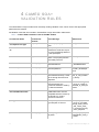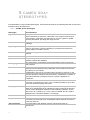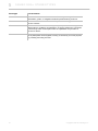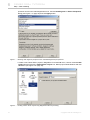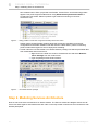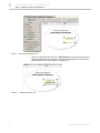
1
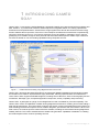
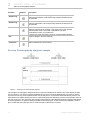
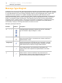
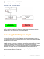
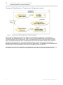
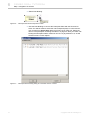
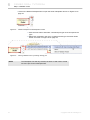
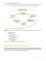
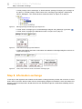
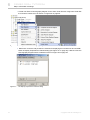
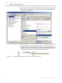
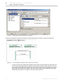
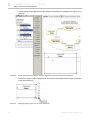
CAMEO SOA+TM PLUGIN
version 17.0.5
No Magic, Inc.
2013
All material contained herein is considered proprietary information owned by No Magic, Inc. and is not to be
shared, copied, or reproduced by any means. All information copyright 2009-2013 by No Magic, Inc.
CONTENTS
1 INTRODUCING CAMEO SOA+ 4
2 INSTALLING AND RUNNING CAMEO SOA+ PLUGIN
5
Installing the CameoSOA+ Plugin 5
Sample of SoaML diagrams 5
3 CAMEO SOA+ DIAGRAMS
6
Services Architecture Diagram 6
Service Architecture diagram elements 7
Service Architecture diagram sample 8
Service Structure Diagram
8
Service Structure diagram elements 9
Service Structure diagram sample 9
Service Choreography Diagram 10
Service Choreography diagram elements 11
Service Choreography diagram sample 12
Message Type Diagram
13
Message Type diagram sample
14
Composit Application Component Diagram
14
Composit Application Component diagram elements 15
Composit Application Component diagram sample 16
4 CAMEO SOA+ VALIDATION RULES
5 CAMEO SOA+ STEREOTYPES
6 CAMEO SOA+ TUTORIAL
17
19
21
Step 1. Start modelling 21
Step 2. Modeling Services Architecture 23
Step 3. The Service Structure 26
Step 4. Integration of services 31
Step 5. Validation errors 34
Step 7. The communication structure 36
Step 8. Information exchange 37
Step 9. Interfaces and Participants 43
Conclusions 45
7 INFORMATION AND SUPPORT
46
Bug Report 46
NoMagic Customer Support System 46
Web page 46
E-Mail 46
Frequently Asked Questions 47
3
Copyright © 2009-2013 No Magic, Inc..
1
INTRODUCING CAMEO
SOA+
Cameo SOA+™ leverages the Unified Modeling Language® (UML®) along with the latest SOA modeling standard, SoaML™, to provide both architects and developers an integrated solution for creating optimal SOA
architectures and implementations. Cameo SOA+ brings together SOA at both the business and technology
levels to address the full spectrum of services. From Enterprise and Business Architectures to implementing,
using and composing services on your favorite enterprise service bus (ESB) or application server, this integrated plug-in is versatile enough for both personal and team-based development. SoaML helps create and
use services based on new and existing capabilities using composite services.
Figure 1 -- SoaML elements modeling using MagicDraw with Cameo SOA+
Cameo SOA+ leverages the latest Model Driven Architecture® (MDA®) standards and technologies making
the transition from model to implementation highly automated, reducing implementation and maintenance
costs. Cameo SOA+ supports all SoaML diagrams, including Service Structure, Service Choreography, Service
Architecture, Message Type, Composite Application Component, Activity, Capability and provisioning.
Cameo SOA+ is packaged as a plugin for the MagicDraw tool and is available for purchase separately. The
Cameo SOA+ retains all capabilities of award-winning MagicDraw architecture modeling environment adding a
SOA specific perspective. The Cameo SOA+ engineer (the specific context of the MagicDraw user interface for
SOA modeling) includes SOA specific menus, toolbars, diagrams, specification and user interface. When in the
SOA context, we meet the specific needs of the SOA modeler, including the same award winning MagicDraw
usability features. This is then extended with the added code generation capabilities of ModelPro™ enabling
the full development from model to operating services.
4
Copyright © 2009-2013 No Magic, Inc.
2
I N S TA L L I N G A N D
RUNNING CAMEO SOA+
PLUGIN
In this section, you will find information on how to install the CameoSOA+ Plugin and how to start working with
CameoSOA+ plugin.
Installing the CameoSOA+ Plugin
To install the CameoSOA+ Plugin, go to the main Help menu and select the command Resource/Plugin Manager. Select the CameoSOA+ Plugin to download and install. After automatic download and installation
restart MagicDraw to activate the plugin.
More about working with Resource Manager, see MagicDraw User Manual.pdf.
If you have already downloaded the CameoSOA+ Plugin, go to the Help main menu and select the
Resource/Plugin Manager. Click the Import button to specify CameoSOA+ Plugin file location. After automatic extraction and installation restart MagicDraw to activate the Plugin.
To install on Mac OS X, copy the CameoSOA+ Plugin file to the MagicDraw installation folder. Then use the
command line to go to the MagicDraw folder and unzip the CameoSOA+ Plugin.
Sample of SoaML diagrams
SoaML sample is included. You may find the SoaML_Diagrams.mdzip project, with all SOA diagrams in the
<MagicDraw installation folder>/samples/Cameo_SOA+.
5
Copyright © 2009-2013 No Magic, Inc.
3
CAMEO SOA+
DIAGRAMS
The Cameo SOA+ Plug-in provides different types of diagrams for the SOA architecture and implementation:
• "Services Architecture Diagram.", on page 6
• "Service Structure Diagram.", on page 8
• "Service Choreography Diagram.", on page 10
• "Message Type Diagram.", on page 13
• "Composit Application Component Diagram.", on page 14
Services Architecture Diagram
The Services Architecture Diagram represents the structure of a services architecture (see Figure 1 on
page 8). It puts a set of services in context of each other and shows how participants work together. A Services
Architecture is a network of participant roles, which provides and consumes services to fulfill a purpose. It
defines for the types of participants and service realizations the requirement, which fulfill those roles. The roles
defines the basic function that an entity may perform in a particular context. In contrast participant specify the
type of a party that fills the role in the context of a specific services architecture. The participants specifies the
type of a party that fills a role inside the services architecture to provide and employ services. The goal of the
services architecture is to specify the SOA of the organization, community or process to provide mutual value.
6
Copyright © 2009-2013 No Magic, Inc.
3
CAMEO SOA+ DIAGRAMS
Services Architecture Diagram
Service Architecture diagram elements
Element
Notation
Description
Service
Architecture
A Services Architecture (an SOA) describes how participants work
together for a purpose by providing and using services expressed
as service.
Participant
Part
A Participant Part is the type of a provider and/or consumer of
services. In the business domain a participant may be a person,
organization or system. In the systems domain a participant may
be a system, application or component.
Agent Part
An Agent Part is a classification of autonomous entities that can
adapt to and interact with their environment.
Service
Contract Use
Service Contract Use is extended to indicate whether the role to
part bindings are strictly enforced or loose.
Role Binding
A role binding is a mapping between features of the collaboration
type and features of the classifier or operation. This mapping
indicates which connectable element of the classifier or operation
plays which role(s) in the collaboration.
Participant
A participant is the type of a provider and/or consumer of services.
In the business domain a participant may be a person, organization
or system. In the systems domain a participant may be a system,
application or component.
Agent
An Agent is a classification of autonomous entities that can adapt
to and interact with their environment.
Service
A Service is the offer of a service by one participant to others using
well defined terms, conditions and interfaces. A Service defines the
connection point through which a Participant offers its capabilities
and provides a service to clients.
Request
A request defines the port through which a Participant makes
requests and uses or consumes services.
Generalization
A generalization is the relationship from the child element (the
more specific element, such as a subclass) to the parent (the more
general element, such as a super class) that is fully consistent with
the first element and that provides additional information.
Realization
A realization is a specialized abstraction relationship between two
sets of model elements, one representing a specification (the
supplier) and the other represents an implementation of the latter
(the client).
7
Copyright © 2009-2013 No Magic, Inc..
3
CAMEO SOA+ DIAGRAMS
Service Structure Diagram
Service Architecture diagram sample
Figure 1 -- Service Architecture diagram sample
Figure 1 illustrates a services architecture involving three participants (dealer, manufacturer, and shipper) and
three services (Place Order Service, Ship Status Service, and Shipping Request Service). This services
architecture shows how a community of dealers, manufacturers, and shippers can work together. Each party
must provide and use the services specified in the architecture. If they do, they will be able to participate in this
community.
This business to business SOA specifies the roles of the parties and the services they provide and use without
specifying anything about who they are, their organizational structure, or internal processes. No “controller” or
“mediator” is required as long as each agrees to the service contracts. By specifying a ServicesArchitecture we
can understand the services in our enterprise and communities in context and recognize the real (business)
dependencies that exist between the participants.
The purpose of the services architecture may also be specified as a comment. Each participant in a
ServicesArchitecture must have a port that is compatible with the roles played in each ServiceContract role it is
bound to.
Service Structure Diagram
A Service Structure Diagram illustrates a Service Contract, defines terms, conditions, interfaces and
choreography that interacting participant must agree to (directly or indirectly) for the services to be enacted.
The full specification of a service which includes all the information, choreography and any other “terms and
conditions” of the service.
The basis of the service contract is also a UML collaboration that is focused on the interactions involved in
providing a service. A participant plays a role in the larger scope of a Services Architecture and also plays a
role as the provider or user of services specified by Service Contracts.
8
Copyright © 2009-2013 No Magic, Inc..
3
CAMEO SOA+ DIAGRAMS
Service Structure Diagram
Service Structure diagram elements
Element
Notation
Description
Service
Contract
A Service Contract defines the terms, conditions, interfaces and
choreography that interacting participants must agree to (directly or
indirectly) for the service to be enacted.
Service
Contract Use
A Service Contract Use is the formalization of a binding exchange
of information, goods, or obligations between parties defining a
service.
Consumer
Part
A Consumer Part defines the interface and responsibilities of a
participant to consume a service. It is used as the type of a
Request.
Provider Part
A Provider Part defines the interface and responsibilities of a
participant to provide a service. It is used as the type of a Service.
Part
A Part of a Service Contract.
Role Binding
A role binding is a mapping between features of the collaboration
type and features of the classifier or operation. This mapping
indicates which connectable element of the classifier or operation
plays which role(s) in the collaboration.
Connector
Each connector may be attached to two or more connectable
elements, each representing a set of instances. Each connector
end is distinct in the sense that it plays a distinct role in the
communication realized over the connector.
Interface
An interface is a specifier for the externally-visible operations of a
class, component, or other classifier (including subsystems)
without a specification of the internal structure.
Service Structure diagram sample
Figure 2 -- Sample of the Service Structure diagram
The example above shows a ServiceContract which defines the terms, conditions, interfaces, and
choreography for the Place Order Service. Further the participants, which must directly or indirectly agree for a
9
Copyright © 2009-2013 No Magic, Inc..
3
CAMEO SOA+ DIAGRAMS
Service Choreography Diagram
interaction and enacted the service. A ServiceContract is a binding contract - binding on any participant that
has a service point typed by a role in a service contract.
Service Choreography Diagram
The choreography is a specification of what is transmitted and when it is transmitted between parties to enact a
service exchange. The service choreography diagram specifies exchanges between the parties - the data,
assets, and obligations that go between the parties. The choreography defines what happens between the
provider and consumer participants without defining their internal processes - their internal processes do have
to be compatible with their ServiceContracts.
10
Copyright © 2009-2013 No Magic, Inc..
3
CAMEO SOA+ DIAGRAMS
Service Choreography Diagram
Service Choreography diagram elements
Element
Notation
Description
Lifeline
Represents the existence of an object at a particular time.
Call Message
A call message represents the request to invoke a specific
operation.
Send
Message
The send message represents asynchronous signal sending to the
target element
Milestone
A Milestone is a means for depicting progress in behaviors in order
to analyze liveliness. Milestones are particularly useful for
behaviors that are long lasting or even infinite.
Alternatives
The interaction operator alt designates that the Combined
Fragment represents a choice of behavior.
The alternative fragment models if…then…else constructions.
Loop
A loop node is a structured activity node that represents a loop with
the setup, test, and body sections.
Option
The interaction operator opt designates that the Combined
Fragment represents a choice of behavior where either the (sole)
operand happens or nothing happens. An option is semantically
equivalent to an alternative Combined Fragment where there is
one operand with non-empty content and the second operand is
empty.
Parallel
The interaction operator par designates that the Combined
Fragment represents a parallel merge between the behaviors of
the operands.
Break
The interaction operator break designates that the Combined
Fragment represents a breaking scenario in the sense that the
operand is a scenario that is performed instead of the remainder of
the enclosing InteractionFragment.
Negative
The interaction operator neg designates that the Combined
Fragment represents traces that are defined to be invalid.
Critical
Region
The interaction operator critical designates that the Combined
Fragment represents a critical region. A critical region means that
the traces of the region cannot be interleaved by other Occurrence
Specifications (on those Lifelines covered by the region).
Consider
The interaction operator consider designates which messages
should be considered within this combined fragment. This is
equivalent to defining every other message to be ignored.
Ignore
The interaction operator ignore designates that there are some
message types that are not shown within this combined fragment.
These message types can be considered insignificant and are
implicitly ignored if they appear in a corresponding execution.
11
Copyright © 2009-2013 No Magic, Inc..
3
CAMEO SOA+ DIAGRAMS
Service Choreography Diagram
Element
Notation
Description
Weak
Sequencing
The interaction operator seq designates that the Combined
Fragment represents a weak sequencing between the behaviors of
the operands.
Strict
Sequencing
The interaction operator strict designates that the Combined
Fragment represents a strict sequencing between the behaviors of
the operands.
Assertion
The interaction operator assert designates that the Combined
Fragment represents an assertion. The sequences of the operand
of the assertion are the only valid continuations. All other
continuations result in an invalid trace.
Interaction
Use
A reference to other interactions such as: communication diagram,
sequence diagram and time diagram.
Duration
Constraint
A duration defines a value specification that specifies the temporal
distance between two time instants.
Service Choreography diagram sample
Figure 3 -- Sample of the Choreography diagram
The sample of choreography diagram shown on Figure 3 illustrates how contract roles must interact to fulfill
service contract. The service contract separates the concerns of how all parties agree to provide or use the
service from how any party implements their role in that service, or from their internal business process. The
requirements for entities playing the roles in a ServiceContract are defined by consumer and provider used as
the type of the role. The consumer and provider types specify the provided and required interfaces that define
all of the operations or signal receptions needed for the role it types - these will be every obligation, asset or
piece of data that the entity can send or receive as part of that service contract.
12
Copyright © 2009-2013 No Magic, Inc..
3
CAMEO SOA+ DIAGRAMS
Message Type Diagram
Message Type Diagram
A Message Type is a kind of value object that represents information exchanged between participant requests
and services. This information consists of data passed into and/or returned from the invocation of an operation
or event signal defined in a service interface. Message Types are used to aggregate inputs, outputs, and
exceptions to service operations as in WSDL. Message Types represent “pure data” that may be
communicated between parties - it is then up to the parties, based on the SOA specification, to interpret this
data and act accordingly. As “pure data” message types may not have dependencies on the environment,
location, or information system of either party - this restriction rules out many common implementation
techniques such as “memory pointers,” that may be found inside of an application. Good design practices
suggest that the content and structure of messages provide for rich interaction of the parties without
unnecessarily coupling or restricting their behavior or internal concerns.
Message Type diagram elements
Element
Notation
Description
MessageTyp
e
A Message Type is a kind of value object that represents information
exchanged between participant requests and services. A Message
Type can illustrate a signal, datatype or a class.
Enumeration
A user-defined data type whose instances are a set of user-specified
named enumeration literals. The literals have a relative order but no
algebras defined on them.
Direct
Composition
A composition is used for aggregations where the life span of the
member object depends on the life span of the aggregate. A directed
relationship represents a relationship between a collection of source
model elements and a collection of target model elements.
Realization
A realization is a specialized abstraction relationship between two
sets of model elements, one representing a specification (the
supplier) and the other represents an implementation of the latter
(the client).
Generalizatio
n
A generalization is the relationship from the child element (the more
specific element, such as a subclass) to the parent (the more
general element, such as a super class) that is fully consistent with
the first element and that provides additional information.
13
Copyright © 2009-2013 No Magic, Inc..
3
CAMEO SOA+ DIAGRAMS
Composit Application Component Diagram
Message Type diagram sample
Figure 4 -- Sample of the Message Type diagram
Figure 4 shows a couple of Message Types that may be used to define the information exchanged between
service consumers and providers. These Message Types may be used as types for operation parameters.
Message Types can have associations with other message and data types.
Composit Application Component Diagram
A Composit Application Component Diagram specifies the architecture for a particular Participant.
It illustrates how sub-participants and external collaborations work together and stand often in relations to a
business process. Although it shows connections to external services over services and requests, which allow
the implementation of service interfaces.
A ParticipantArchitecture describes how internal participants work together for a purpose by providing and
using services expressed as service contracts. The participant architecture is a kind of services architecture for
a particular participant. By expressing the use of services, the ParticipantArchitecture implies some degree of
knowledge of the dependencies between the participants in the context of the containing participant. A
participant architecture is similar to the ServicesArchitecture and the similar parts of the descriptions will be not
repeated here, for a detailed view look in the description of the ServiceArchitecture diagram. The only
difference is that a participant architecture is based on a structured classifier rather than a collaboration and
can therefore for external ports that represent interactions with external participants. A Participant may play a
role in any number of services architecture thereby representing the role a participant plays and the
requirements that each role places on the participant.
14
Copyright © 2009-2013 No Magic, Inc..
3
CAMEO SOA+ DIAGRAMS
Composit Application Component Diagram
Composit Application Component diagram elements
Element
Notation
Description
Participant
A participant is the type of a provider and/or consumer of services.
In the business domain a participant may be a person, organization
or system. In the systems domain a participant may be a system,
application or component.
Participant
(Component)
A Participant Component is the type of a provider and/or consumer
of services. In the business domain a participant may be a person,
organization or system. In the systems domain a participant may be
a system, application or component.
Agent
An Agent is a classification of autonomous entities that can adapt to
and interact with their environment.
Agent
(Component)
An Agent Component is a classification of autonomous entities that
can adapt to and interact with their environment.
Part
Part represents a set of instances that are owned by a containing
classifier instance.
Service
Contract Use
ServiceCollaborationUse is extended to indicate whether the role to
part bindings are strictly enforced or loose.
Request
A request defines the port through which a Participant makes
requests and uses or consumes services.
Service
A Service is the offer of a service by one participant to others using
well defined terms, conditions and interfaces. A Service defines the
connection point through which a Participant offers its capabilities
and provides a service to clients.
Role Binding
A role binding is a mapping between features of the collaboration
type and features of the classifier or operation. This mapping
indicates which connectable element of the classifier or operation
plays which role(s) in the collaboration.
Service
Channel
A communication path between Services and Requests within an
architecture.
Assembly
Connector
An assembly connector is a connector between two components
that defines that one component provides the services that another
component requires.
Delegation
Connector
A delegation connector is a connector that links the external
contract of a component (as specified by its ports) to the internal
realization of that behavior by the component parts.
Realization
A realization is a specialized abstraction relationship between two
sets of model elements, one representing a specification (the
supplier) and the other represents an implementation of the latter
(the client).
15
Copyright © 2009-2013 No Magic, Inc..
3
CAMEO SOA+ DIAGRAMS
Composit Application Component Diagram
Composit Application Component diagram sample
Figure 5 -- Sample of the Composite Application Component diagram
Figure 5 shows a participant’s services architecture. The “Manufacturer component” is composed of
“Accounting” and “Order Processing.” The “seller” service port on the Manufacturer component shows the
external responsibility of the manufacturer, which is then delegated to the accounting and order processing
parts. In participant architecture there are frequently services connected between internal roles or between
internal roles and external ports. The “Order Fulfillment Service” shows a service that is internal to the
Manufacturer while both the “InvoicingService” and “Place Order Service” are delegated from the Manufacturer
component to the internal participants, Accounting, and OrderProcessing, respectively.
The business process of the manufacturer is the behavior that may be associated with the participant’s services
architecture. Each role in the architecture corresponds with a swim lane or pool in the business process.
16
Copyright © 2009-2013 No Magic, Inc..
4
CAMEO SOA+
VA L I D A T I O N R U L E S
The CameoSOA+ Plugin includes a list of already existing validation rules, which check if the appropriate
parameters are defined.
All validation rules that are included in CameoSOA+ Plugin are listed in table below.
TABLE 1. Cameo SOA+ validation rules for SoaML models
Constrained Name
Constrained
Element
Error Message
Abbreviation
port type must
correspond role type
Property
Port with property type must
exits
PortType
hasPortsForAllBoundRol
es
ServiceArchitecture
Each participant in a Services
Architecture shall have a port
for each role binding attached
to that participant.
PA
isActive
Agent
Agents should always be
active. The property isActive
must always be true.
AGENT_ACTIVE
noOwnedBehaviors
MessageType
Message Type cannot contain
owned behaviors.
MType_cannot_contai
n_ownedBehaviors
noOwnedOperations
MessageType
Message Type cannot contain
owned operations.
MessageType_cannot
_contain_ownedOper
ations
noRealizedUsedInterface
Participant
A Participant cannot realize or
use Interfaces directly, it must
do so through Services and
Requests.
Participant_cannot_re
alize_or_use_Interfac
es_directly
partsAreInterfaces
ServiceInterface
All parts of a ServiceInterface
must be typed by the
Interfaces realized or used by
the ServiceInterface.
ServiceInterface_part
s_must_be_typed_by
_realized_or_used_int
erfaces.
partsCompatibleWithRol
esForCollaborationUse
ServiceContract
All parts connected to
CollaborationUse must be
compatible with the roles they
are bound to in a strict
services architecture.
SA
portTypes
Participant
Participant ports must be of
type Request or Service.
Participant_capabilitie
s_must_be_provided_
through_some_Servic
e_and_needs_must_
be_consumed_throug
h_some_Request.
publicAttributes
MessageType
Message Type attributes must
be public.
MessageType_All_ow
nedAttributes_must_b
e_Public
17
Copyright © 2009-2013 No Magic, Inc.
4
CAMEO SOA+ VA LIDATION RULES
Constrained Name
Constrained
Element
Error Message
Abbreviation
requestType
Request
Request type must be
Interface or ServiceInterface.
RequestType
serviceChannelEndsCom ServiceChannel
patible
The Request and Service
ports must have compatible
types
SC
serviceChannelEndTypes ServiceChannel
One end of a ServiceChannel
must be a Request and the
other a Service in an
architecture.
SC
Service type must be Interface
or ServiceInterface.
ServiceType
serviceType
NOTE
18
Service
For more informations about validation rules, see “MagicDraw
UserManual.pdf”.
Copyright © 2009-2013 No Magic, Inc..
5
CAMEO SOA+
ST E R E O T Y P E S
The CameoSOA+ Plugin includes Stereotypes, which will be illustrate in the following table with a short documentation which describes them.
TABLE 1. SoaML profile stereotypes
Stereotype
Documentation
Agent
An Agent is a classification of autonomous entities that can adapt to and
interact with their environment. It describes a set of agent instances that
have features, constraints, and semantics in common. Agents in SoaML
are also participants, providing and using services.
Attachment
A part of a Message that is attached to rather than contained in the
message.
Capability
A Capability is the ability to act and produce an outcome that achieves a
result. It can specify a general capability of a participant as well as the
specific ability to provide a service.
Collaboration
Abstract stereotype for Service Contract and Service Architecture common
features.
Consumer
Defines Interface for consumer role in Service Contact.
Expose
A dependency between a service interface and a capability. The service
interface exposes the capability.
MessageType
The specification of information exchanged between service consumers
and providers.
Milestone
A Milestone is a means for depicting progress in behaviors in order to
analyze liveness. Milestones are particularly useful for behaviors that are
long lasting or even infinite.
Participant
A participant is the type of a provider and/or consumer of services. In the
business domain a participant may be a person, organization or system. In
the systems domain a participant may be a system, application or
component.
Port
Port is extended with a connectorRequired property to indicate whether a
connector is required on this port, or the containing classifier may be able
to function without anything connected.
Property
The Property stereotype augments the standard UML Property with the
ability to be distinguished as an identifying property meaning the property
can be used to distinguish instances of the containing Classifier. This is
also known as a “primary key”. In the context of SoaML the ID is used to
distinguish the correlation identifier in a message.
Provider
Defines Interface for provider role in Service Contract.
Request
A Request models the use of a service by a participant and defines the
connection point through which a Participant makes requests and uses or
consumes services.
ServiceChannel
A communication path between Service and Request within an
architecture.
19
Copyright © 2009-2013 No Magic, Inc.
5
CAMEO SO A+ ST EREOTYPES
Stereotype
Documentation
ServiceContract
A ServiceContract is the formalization of a binding exchange of
information, goods, or obligations between parties defining a service.
ServiceInterface
Defines the interface to a Service or Request and is the type of a role in a
service contract.
Service
A Service is the offer of a service by one participant to others using well
defined terms, conditions and interfaces. A Service defines the connection
point through which a Participant offers its capabilities and provides a
service to clients.
ServicesArchitecture
The high-level view of a Service Oriented Architecture that defines how a
set of participants works together, forming a community, for some purpose
by providing and using services.
20
Copyright © 2009-2013 No Magic, Inc..
6
CAMEO SOA+
TU T OR IA L
This tutorial provides a step-by-step instructions for easy start in the world of service oriented architecture
using the Cameo SOA+ plug-in of MagicDraw.
You will learn how to create and structure new project. In the next steps you will create a Services Architecture
and Participants, how to create a high level view of the services by defining service contracts.
We will start by the definition of a problem area community, that means how a set of participants work together
for some purpose by providing and using services. Later we will refine the services and message details.
The “community” in this case is a set of manufactures, dealers and shippers. the described architecture could
be created by a trade organization or a major player. In this tutorial we will call this community the Dealer Network. The intend of this architecture is to allow a marketplace of dealers, manufactures and shippers work
together easily by:
• Allowing existing and new “players” in the marketplace by provided and use each others
services as defined in the architecture.
• Defining these services to be independent of any participant technologies or internal business
processes.
• Having well defined “contracts” for how they work together.
Step 1. Start modelling
In this step we will prepare environment and create a new project for modelling our new architecture. We will
use SOA Engineer MagicDraw perspective for more efficient modelling.
1. Switch current MagicDraw perspective to the SOA Engineer perspective. Switching to this per-
spective will hide all non SOA relative MagicDraw menus. Select Options->Perspectives->Per-
21
Copyright © 2009-2013 No Magic, Inc.
6
CAMEO SOA+ TUTORIAL
Step 1. Start modelling
spectives and from the main MagicDraw menu. Choose SOA Engineer in Select Perspective
dialog (see Figure 1 on page 22) and click Apply button.
Figure 1 -- Selecting SOA Engineer perspective from available MagicDraw perspectives
2. Create a new Cameo SOA+ project in MagicDraw. From the File menu, choose command New
Project and then select the Cameo SOA+ Project icon. Name project DealerNetwork and click
OK button (see Figure 2 on page 22).
Figure 2 -- Creating Cameo SOA+ Project using MagicDraw New Project dialog
22
Copyright © 2009-2013 No Magic, Inc..
6
CAMEO SOA+ TUTORIAL
Step 2. Modeling Services Architecture
New created Cameo SOA+ project will have SoaML, Cameo SOA+ and Provisioning profiles
applied. This profile might be hidden/shown using Show Auxiliary Resources button in
Containment tree toolbar. Hide this profiles to get model tree showing our services
architecture only.
Figure 3 -- Hiding profiles in model tree using Show Auxiliary Resources button
SoaML profile contains SoaML modeling language stereotypes. Modeling environment
configurations and SoaML validation rules are stored in Cameo SOA+ profile. Provisioning
profile contains stereotypes for service deployment modeling.
3. Create under the root Data model a new Dealer Network package. We will keep all Dealer Net-
work related data and services there:
3.1 Right-click on the Data root model in Containment tree and select New Element->Package from the context menu.
3.2 Type the package name Dealer Network.
Figure 4 -- The Dealer Network package
Step 2. Modeling Services Architecture
Now we will create service architecture for Dealer Network. The Service Architecture diagram shows how different roles work together and interacts with each other. In this step we will create the services architecture with
defined participants.
23
Copyright © 2009-2013 No Magic, Inc..
6
CAMEO SOA+ TUTORIAL
Step 2. Modeling Services Architecture
1. Create new Services Architecture package in Dealer Network package as shown on Figure 5
on page 24. for keeping our services architecture.
Figure 5 -- Package for Services Architecture
2. Create new Services Architecture diagram in the Services Architecture package for describing
service architecture. Right click on the Services Architecture package In containment tree and
select New Diagram->Cameo SOA+->Service Architecture Diagram. Name created diagram
as DNA Services Architecture Network.
3. Draw a Service Architecture
3.1 In Services Architecture diagram toolbar click the Service Architecture button
and click on the diagram pane to draw the Service Architecture shape.
3.2 Type in the name of Services Architecture as Dealer Network Architecture (see
Figure 6 on page 24)
Figure 6 -- Dealer Network Architecture in Service Architecture Diagram
4. Create three Participant Parts for Dealer, Shipper and Manufacturer in the Dealer Network
Architecture:
4.1 In the diagram toolbar click the Participant Part button
. Click on the
Dealer Network Architecture collaboration shape to draw the participant part.
24
Copyright © 2009-2013 No Magic, Inc..
6
CAMEO SOA+ TUTORIAL
Step 2. Modeling Services Architecture
Figure 7 -- New created Participant Part
4.2 Click on Participant Part and type “: Manufacturer” when press Ctrl+Enter to
apply entered name (see Figure 8 on page 25). MagicDraw will create Participant Manufacturer too (see Figure 9 on page 26).
Figure 8 -- Naming Participant Part
25
Copyright © 2009-2013 No Magic, Inc..
6
CAMEO SOA+ TUTORIAL
Step 3. The Service Structure
Figure 9 -- Automatically created Manufacturer participant in the model
You may use Show Applied Stereotype button from Containment tree to enable/disable showing stereotypes in
the model tree (see Figure 10 on page 26)
Figure 10 -- Disabling/enabling showing stereotype in model tree.
4.3 Repeat the steps 3.1 and 3.2 to create two more Participant Parts, name them
“:Dealer” and “:Shipper”.
Figure 11 -- Dealer Network Architecture Service Architecture with Participant Parts inside
Step 3. The Service Structure
In this step we will specify the agreements between the parties which consume and provide service. For this we
will create three Service Structure diagrams, the Service Contracts to each service. Theses ServiceContracts
will specify the roles of the provider and the consumer which can be filled out from any participant of our Dealer
26
Copyright © 2009-2013 No Magic, Inc..
6
CAMEO SOA+ TUTORIAL
Step 3. The Service Structure
Network. The Service Contract will also define which informations, products, assets, value and obligations will
flow between these two parties.
1. Create package Services in Dealer Network package. We will keep our services there.
Figure 12 -- Package for Services
2. In Services package create Place Order Service package and a Service Structure diagram in
the Place Order Service package. Use New Diagram->Cameo SOA+ ->Service Structure
Diagram from Place Order Service package context menu. Name new Service Structure diagram as a Place Order Service.
Figure 13 -- Place Order Services package and the diagram
3. Draw a Service Contract element in the Service Structure diagram, using the Service Con-
tract button
from the diagram toolbar and name created Service Contract as Place Order
(see Figure 14 on page 28).
27
Copyright © 2009-2013 No Magic, Inc..
6
CAMEO SOA+ TUTORIAL
Step 3. The Service Structure
3.1 Name ServiceContract as Place Order and close dialog.
Figure 14 -- The Service Contract element named Place Order
4. Create provider in the Place Order Service Contract element using the Provider Part
button from the diagram toolbar and name it as “provider : Order Take”.
Figure 15 -- Place Order Service Contract with Service Interface Part.
28
Copyright © 2009-2013 No Magic, Inc..
6
CAMEO SOA+ TUTORIAL
Step 3. The Service Structure
5. Create consumer in the Place Order Service Contract element using the Consumer Part
button from the diagram toolbar and name it as “consumer : Order Placer”.
Figure 16 -- Place Order Service Contract with consumer and provider
6. Connect consumer with provider using Connector from consumer smart manipulator (see
Figure 17 on page 29 and Figure 18 on page 29)
Figure 17 -- Smart manipulator toolbar of the Service Interface, the Connector relationship.
Figure 18 -- Place Order Service Contract with consumer connected to provider
29
Copyright © 2009-2013 No Magic, Inc..
6
CAMEO SOA+ TUTORIAL
Step 3. The Service Structure
Figure 19 -- Model with the Service Contract for Place Order and Interfaces
7. Repeat the steps 1 to 6 to create Shipping Request Services package and the Service Struc-
ture diagram with consumer and provider as shown on Figure 20 on page 30.
Figure 20 -- The Shipping Request Service Contract with consumer and provider
Figure 21 -- Model with the Service Contract for Shipping Request and Interfaces
30
Copyright © 2009-2013 No Magic, Inc..
6
CAMEO SOA+ TUTORIAL
Step 4. Integration of services
8. Repeat the steps 1 to 6 to create one more Ship Status Service as shown on Figure 22 on
page 31.
Figure 22 -- Ship Status Service Contract with consumer and provider
Figure 23 -- Model with the Service Contract for Ship Status and Interfaces
Step 4. Integration of services
We have to defined the ServiceContracts to the services. Now we need to integrate the created services into
our service architecture. Further to connect them with the participants which uses them by playing the defined
rules, which we set in the service contracts.
1. Open DNA Service Architecture diagram and Drag and Drop created service contracts from
Containment tree (see Figure 24 on page 32) in to the Dealer Network Service Architecture
31
Copyright © 2009-2013 No Magic, Inc..
6
CAMEO SOA+ TUTORIAL
Step 4. Integration of services
(see Figure 11 on page 26). You will get Service Contract Usages as shown in Figure 25 on
page 32.
Figure 24 -- Service Contracts to drag and drop to the Dealer Network Service Architecture
Figure 25 -- Service Architecture with usages of Service Contracts
2. Connect the Participant Parts with Service Contract Usages and select the role specific partici-
pant plays under specific service contract context.
2.1 Select the Participant Part the smart manipulator toolbar.
32
Copyright © 2009-2013 No Magic, Inc..
6
CAMEO SOA+ TUTORIAL
Step 4. Integration of services
2.2 Select Role Binding.
Figure 26 -- Participant Part Smart manipulator toolbar
2.3 Use the Role Binding to connect the Participant Parts with the ServiceCon-
tracts. You will be asked to select the role Participants plays in connected service contract from Select Role dialog (see Figure 27 on page 33). Select the
role for each participant according the Table 1 on page 34. After you create role
binding the Participant will be marked in red. Do not pay attention to it; we will
solve this errors in next chapter.
Figure 27 -- Participant Role selecting dialog for connected Service Contract
33
Copyright © 2009-2013 No Magic, Inc..
6
CAMEO SOA+ TUTORIAL
Step 5. Validation errors
TABLE 1. Roles of the Participants in the Service Architecture
Participant
Role
ServiceContract
Manufacturer
provider
Place Order
Dealer
consumer
Place Order
Dealer
consumer
Ship Status
Shipper
provider
Ship Status
Shipper
provider
Shipping Request
Manufacturer
consumer
Shipping Request
Figure 28 -- Service Architecture including Role Binding
NOTE
The red marks on the participant parts display validation errors, these
will be described in the next step.
Step 5. Validation errors
At step 4 we got an error message of active validation rules. Errors are marked as a red frame around the element that causes the error. To solve these errors, we will now create the missing Ports.
34
Copyright © 2009-2013 No Magic, Inc..
6
CAMEO SOA+ TUTORIAL
Step 5. Validation errors
1. Click on the Dealer Participant Part to open the smart manipulator shown on Figure 29 on
page 35
Figure 29 -- Dealer Participant Smart Manipulator toolbar
1.1 Click the error button and select “command port type must correspond role
type“.
1.2 Select first command in the menu “Create port with type Consumer Order
Placer“ as shown on Figure 30 on page 35
Figure 30 -- Solving validation error by creating missing port
NOTE
35
The Participant Part will stay marked, because we still need to create
one more port for the Participant Part.
Copyright © 2009-2013 No Magic, Inc..
6
CAMEO SOA+ TUTORIAL
Step 7. The communication structure
2. Create missing ports in same way for the Participant Parts Manufacturer and Shipper.
Figure 31 -- Service Architecture with solved validation errors
You may see created port by expanding Dealer, Shipper and Manufacturer classes as shown on Figure 32 on
page 36.
Figure 32 -- Automatically created ports after validation error solved
Step 7. The communication structure
In this step we will define MessageTypes with the attributes for the interaction between provider and consumer
in created ServiceContracts. A MessageType is a kind of value object that represents information exchange
between participant requests and services.This information includes data passed into and/or returned from the
invocation of an operation or event signal defined in a service interface.
36
Copyright © 2009-2013 No Magic, Inc..
6
CAMEO SOA+ TUTORIAL
Step 8. Information exchange
1. Create package named “Messages“ in “Dialer Network“ package for keeping our messages in
one place. In created package create Cameo SOA+ “Message Type Diagram“ diagram and
name it “Messages“. Your model structure will look as shown on Figure 33 on page 37
Figure 33 -- Message package and Message Type Diagram in it
2. Create “Order“ message type in created Messages diagram using Message Type button
.
3. Create “Order“ message type attributes as shown on Figure 34 on page 37.
Figure 34 -- Order Status message type with attributes
4. Create Order Status and Order Confirmation with attributes in Messages diagram as shown on
Figure 35 on page 37.
Figure 35 -- Order, Order Status and Order Confirmation message types
Step 8. Information exchange
In this step we will regularize and visualize the information exchange between provider and consumer of “Place
Order“ Service Contract. We will create a Service Choreography diagram to illustrate the exact information flow
between consumer and provider. We will show how new operations might be created while modeling Service
Choreography.
37
Copyright © 2009-2013 No Magic, Inc..
6
CAMEO SOA+ TUTORIAL
Step 8. Information exchange
1. Create new Service Choreography diagram for the Place Order Service using Place Order Ser-
vice Contract context menu as shown on Figure 36 on page 38.
Figure 36 -- Creating new Service Choreography diagram for Place Order service contract
2. Make sure consumer and provider are selected for displaying them as life lines and click Ok
button in Display Properties as Lifelines dialog (see Figure 37 on page 38). Lifelines in Service
Choreography diagram will be created as shown on Figure 38 on page 39.
Figure 37 -- The Display Properties as Lifelines dialog
38
Copyright © 2009-2013 No Magic, Inc..
6
CAMEO SOA+ TUTORIAL
Step 8. Information exchange
Figure 38 -- The Place Order Choreography diagram
3. Now we may create operation call message from Order Placer to Order Taker for taking order.
This operation call illustrates how consumer asks provider to take an order. Order Taker will
notify consumer about order status.
3.1 Click on
Call Message button in Service Choreography diagram toolbar
and draw message call from consumer (Order Placer) to provider (Order Taker)
as shown on Figure 39 on page 39.
Figure 39 -- The Place Order Choreography diagram, Quote request Call Message
3.2 Click on the small green round button on created Call message to create new
operation to call (see Figure 40 on page 39).
Figure 40 -- Smart manipulator on Call message for new operations
3.3 In Operation specification window specify operation name as takeOrder, its
type as Order Confirmation (see Figure 41 on page 40) and create new parameter named as newOrder of type Order (see Figure 42 on page 40).
39
Copyright © 2009-2013 No Magic, Inc..
6
CAMEO SOA+ TUTORIAL
Step 8. Information exchange
Figure 41 -- New Created Operation specification dialog
Figure 42 -- New parameter for created takeOrder operation
3.4 Create a Send Message from provider to consumer in order to show that pro-
vider notify consumer about order status. Use Send Message button
diagram toolbar for Send Message modeling.
40
from
Copyright © 2009-2013 No Magic, Inc..
6
CAMEO SOA+ TUTORIAL
Step 8. Information exchange
3.5 Double click on the created Send Message to open its Specification window. In
Specification window select Order Status message type for Signal property
(see Figure 43 on page 41).
Figure 43 -- Specifying Send Message message type using Send Message Specification window and Signal property
3.6 Click round button on Send Message message to create signal reception in
consumer Order Placer (see Figure 44 on page 41). MagicDraw will open created signal reception Specification dialog (see Figure 45 on page 42). Just
close this dialog as we do not need to modify there anything.
Figure 44 -- Creating new signal reception for Order Status signal in Order Placer
41
Copyright © 2009-2013 No Magic, Inc..
6
CAMEO SOA+ TUTORIAL
Step 8. Information exchange
Figure 45 -- Specification dialog of created signal reception.
Service Choreography for Place Order Service contract should look as shown on Figure 46 on page 42.
Figure 46 -- The Choreography diagram for Place Order service contract
In order to specify that message flow between Order Placer and Order Taker may take place we
should create usage dependencies between Order Places and Order Taker interfaces. You may
do it by drag and dropping Order Placer and Order Taker interfaces from Containment tree to the
Place Order Service Structure diagram and connect them using Usage relationship from smart
manipulator (see Figure 47 on page 43 and Figure 48 on page 43).
42
Copyright © 2009-2013 No Magic, Inc..
6
CAMEO SOA+ TUTORIAL
Step 9. Interfaces and Participants
Figure 47 -- Drag and Dropped Order Placer with Order Taker interfaces to the Place Order Service Contract diagram
Figure 48 -- Usages between Order Placer and Order Taker
Step 9. Interfaces and Participants
In this step we will find out how to visualize Ports of service Participants.
1. Go into the Services Architecture package and open the DNA Service Architecture Network
diagram.
43
Copyright © 2009-2013 No Magic, Inc..
6
CAMEO SOA+ TUTORIAL
Step 9. Interfaces and Participants
2. Drag and drop Dealer, Manufacturer and Shipper Participants to the diagram (see Figure 49 on
page 44).
Figure 49 -- Dealer, Manufacturer and Shipper drag and dropped in to the Service Architecture diagram
3. Click on the Shipper class in diagram and use its smart manipulator button to display ports (see
Figure 50 on page 44).
Figure 50 -- Displaying Shipper ports using its smart manipulator
44
Copyright © 2009-2013 No Magic, Inc..
6
CAMEO SOA+ TUTORIAL
Conclusions
4. Click on one of the Shipper ports and use port smart manipulator button to show selected port
provided/required interfaces (see Figure 51 on page 45). MagicDraw will display Shipper Ports
Specification window. Just close it as we do not need to modify anything.
Figure 51 -- Showing provided/required interfaces of port using port smart manipulator
5. Repeat 3 and 4 steps in order to display other Participants ports and its provided/required inter-
faces.
Figure 52 -- Participants with Ports and the Provided/Required Interfaces
Conclusions
Congratulations, you have successfully finished the first tutorial of the Cameo SOA+ in MagicDraw UML and
made the first steps into the world of service oriented architecture.
You learned how to create and structure a new SoaML project. Create a high level view on services by defining
them in service contracts and create a Service Architecture and Participants.
You learned about defining a community and how participants of this community work together for some purpose by providing and using services.
NOTE
45
This tutorial is the first version of the Cameo SOA+ tutorial. It does not
describe all functionality of Cameo SOA+ plug-in. All functionality
description will be available in the new tutorial version.
Copyright © 2009-2013 No Magic, Inc..
7
INFORMATION AND
SUPPORT
Bug Report
Your bug reports are welcome at [email protected]. These reports allow us to fix bugs as soon as possible and release the known-bug-free maintenance releases. While sending the bug report, please include (if
applicable):
• MagicDraw version number and the name of the edition (Standard, Enterprise, Professional
Java, Professional C#, Demo, or Academic).
• Sources where you got the version from (demo CD or our homepage downloaded).
• Your OS name and version.
• JDK version and JVM vendor.
• Cameo SOA+ plugin version and revision. This information can be found in "Help->About
Magic Draw-> Info" page.
For information about your JVM and OS, see Info tab in About dialog from MagicDraw Help menu. If you have
a file that the MagicDraw is not able to load and it is not a confidential one, please, attach it as well. This would
help us to analyze the problem.
Bugs can be submitted directly from MagicDraw application - Help->Submit a Bug.
NoMagic Customer Support System
Please visit http://www.nomagic.com/support.html for No Magic Customer Support System.
Web page
To download the demo version and to get contact information, please visit the Cameo SOA+ web page.
E-Mail
[email protected] - for questions about product installation, features, questions like "How do I...", and
suggestions.
[email protected] - questions regarding academic and site discounts, delivery, customer profile, invoices
and related issues.
[email protected] - email for all other contact
46
Copyright © 2009-2013 No Magic, Inc.
7
INFORMATION AND SUPPORT
Frequently Asked Questions
We are awaiting your comments and suggestions. Do not miss the chance to see your desired features in the
future versions!
Frequently Asked Questions
Please visit our website for FAQ at http://www.nomagic.com/support/faq.html.
47
Copyright © 2009-2013 No Magic, Inc..