1
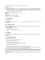
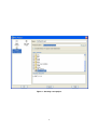
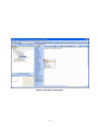
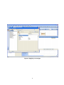
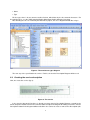
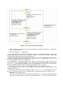
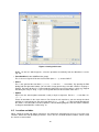
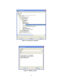
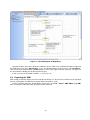
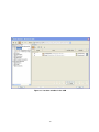
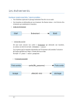
Minerva - User Manual
Zsolt Kiss Gere
January 28, 2008
Contents
1 Minerva Overview
1
2 Technical info
1
3 Deployment
3.1 Install . . . . . . . . . . . . . . . . . . . . . . . . . . . . . . . . . . . . . . . . . . . . . . . . .
3.2 Configure/Usage . . . . . . . . . . . . . . . . . . . . . . . . . . . . . . . . . . . . . . . . . . .
2
2
2
4 Tutorial
4.1 Creating the project . . . . . . . . . . .
4.2 Modeling the types and data structures
4.3 Creating the service description . . . . .
4.4 Creating the Service State Machine . .
4.5 Location variables . . . . . . . . . . . .
4.6 Exporting the SSM . . . . . . . . . . . .
1
.
.
.
.
.
.
.
.
.
.
.
.
.
.
.
.
.
.
.
.
.
.
.
.
.
.
.
.
.
.
.
.
.
.
.
.
.
.
.
.
.
.
.
.
.
.
.
.
.
.
.
.
.
.
.
.
.
.
.
.
.
.
.
.
.
.
.
.
.
.
.
.
.
.
.
.
.
.
.
.
.
.
.
.
.
.
.
.
.
.
.
.
.
.
.
.
.
.
.
.
.
.
.
.
.
.
.
.
.
.
.
.
.
.
.
.
.
.
.
.
.
.
.
.
.
.
.
.
.
.
.
.
.
.
.
.
.
.
.
.
.
.
.
.
.
.
.
.
.
.
.
.
.
.
.
.
.
.
.
.
.
.
.
.
.
.
.
.
.
.
.
.
.
.
2
.
2
.
4
.
7
.
8
. 10
. 12
Minerva Overview
Minerva is a tool for using SSM models designed in MagicDraw in the testing environment of Jambition.
It reads such models and converts them to an internal representation, suitable to be used by Jambition
to test a web service. It also contains showWSDL and other library utilities called by Jambition in order to
accomplish its validation and testing activities.
2
Technical info
Provider 4D Soft Ltd.
Introduction Minerva is a library containing the following services:
• showWSDL This is a tool which parses a WSDL document and outputs its structure in a human
readable format.
• getSSMFromWSDL
This command takes a WSDL document and an SSM XML description and creates an internal
representation of the SSM, passing it to Jambition for testing a web service.
• getSSMFromUML
This call takes an XMI file, containing an UML representation of an SSM model and generates
an internal SSM used further by Jambition for testing and validating a web service.
Development status The currently available version is 2.0.
Intended audience Software developers who wish to validate and functionally test their services designed
conform to the SP SSM model and modelled with the MagicDraw UML tool.
1
License This software is open source. GPL version 3 license is used.
Language Java
Environment (set-up) Minerva runs in a Java environment, so a Java 5 or higher Runtime Environment
is needed in order to use it. The libraries used are open-source and packaged with the installation.
Because it is a library for Jambition, a Jambition installation is also needed. There are no special
hardware or software requirements beside this.
Platform Java Runtime Environment 5 or later.
Download http://plastic.isti.cnr.it/download/tools
Documents Javadoc API, this guide.
Contact Zsolt G. Kiss, [email protected]
3
Deployment
3.1
Install
To install Minerva, unzip the archive showWSDL.zip in a directory of choice, referred later as $MINERVA_HOME
in this document.
3.2
Configure/Usage
The java (version ≥ 5.0) should be in the PATH, other configuration is not needed. The used libraries are
contained in the package.
ShowWSDLElements tool usage:
1. Change directory to $MINERVA_HOME
2. Type java -jar showWSDL.jar <wsdl-uri>
4
Tutorial
We’ll follow the steps of modeling the Warehouse service, described in the Jambition chapter, with an SSM,
using MagicDraw.
4.1
Creating the project
First we create a Plastic project.
• From the File menu, choose New Project
The New Project dialog box opens.
1. Select the Project from Template icon.
2. Specify the name (e.g. Warehouse) in the Name text box.
3. Choose the Project Location.
4. Select Plastic Template from the templates available and click Ok (fig. 1).
Click on the <Top Level Service Name> in the Containment browser and rename it to Warehouse
(choose Rename from the context menu, obtained by right-clicking the name.)
The created Plastic project contains the necessary module imports (Plastic Profile and UML Standard
Profile) and a package structure already based on the Plastic Conceptual Model, containing the 5 basic
views. For the SSM we are interested mainly on the Service View, which consists of a Structural View and
a Behavioral View.
Next we need to model the composite and other user-defined types which will be used through the
project.
2
Figure 1: Creating a new project
3
Figure 2: The basic types and data structures
4.2
Modeling the types and data structures
The Warehouse example contains the following user-defined types: Product, Address, Quote and QuoteRequest.
These are shown in Fig. 2.
We model these types in a class diagram:
1. From the elements browser pane on the left choose, then right-click “Warehouse — 002.Service View
— Structural View”.
2. Select New Diagram — Class Diagram, and specify a name (WarehouseTypes)
3. Add the type elements to the diagram, using the Class and Enumeration shape buttons on the diagram
toolbar, found in the “Class Diagram” button group.
First create the enumeration called Product. On the Class Diagram toolbar click the arrow found at the
right side of the Class button, then select Enumeration (fig. 3):
Create the enumeration by clicking on the canvas. Then, open the specification dialog and set the
name (“Product”) and the desired values. For the values, click “Enumeration Literals” on the left pane of
the specification dialog, then press the “Create” button for each String literal you want to add. Specifying a
name for a literal is enough.
Next create the classes similarly. For each class specify the Name, Applied Stereotype and the class
Attributes.
To set the stereotype, click on the Value cell of the Applied Stereotype line in the specification dialog.
Then click the small rectangle button on the right side, labelled [. . . ]. This will open a list box containing
all stereotypes which can be applied to the element. Typing “d” the list will be filtered to the stereotypes
starting with “d” – in our case the list will contain only one element, “DataType”, defined in the Plastic Profile.
Select this element with the check box and click Apply (fig. 4).
Next define the class attributes. Select Attributes in the left browser tree of the specification dialog, then
hit Create.
The following data should be specified for each attribute:
4
Figure 3: Creating an enumeration
5
Figure 4: Applying a stereotype
6
• Name
• Type
For the type, there is also a context-sensitive list box, which filters by the first entered characters. For
the primitive types, use the [UML Standard Profile::MagicDraw Profile::datatypes] package.
After defining the classes needed by the Warehouse project, the class diagram will look like in fig. 5.
Figure 5: The warehouse types diagram
The next step is the specification of services. For this, the Service Description Diagram will be used.
4.3
Creating the service description
Next, we create the service (fig. 6):
Figure 6: The service
In the Service Structural View there is already an empty Service Description Diagram, created by the
Plastic template. Double-click it in the elements browser to open the diagram for editing. Select the “Service
Description” button in the diagram toolbar and click in the canvas to create a new Service Description (this
7
is the service interface.) Open its specification dialog and enter “Warehouse” for the name. Then choose
Operations on the left browser pane and add the necessary operations.
For each operation we should define the following:
• Name
• Kind (REQUEST RESPONSE, ONE WAY, NOTIFICATION or SOLICIT RESPONSE)
• Parameters
For each parameter, we should specify:
• its name
• type (primitive, or user-defined, as discussed above) and
• direction (in, out, inout or return)
Note: you have to define a parameter for the return value, which has to be unique between all parameter
names (e.g.: rq return, and not just return)
After defining the service description, the service diagram will look like in fig. 7.
Figure 7: The service diagram
Then we can move on specifying the services dynamic behavior, with the SSM.
4.4
Creating the Service State Machine
Now follows the most interesting part of the design, specifying the SSM. We define this by drawing an SSM
diagram, which will look like in fig. 8.
We will create an SSM for our Warehouse service.
8
Figure 8: The service state machine diagram
1. From the elements tree browser pane on the left choose, then right-click “Warehouse — 002.Service
View — Behavioral View”.
2. Select New Diagram — JSSM Diagram.
At this point, MagicDraw has done the following: it created an SSM called “Untitled1” and an SSM
Diagram underneath, as a child element, called also “Untitled1”. To rename the elements, right-click on
each of them and choose Rename from the context menu.
Double-clicking on the newly created diagram name will open the diagram window. The toolbar will have
a group called “JSSM Diagram” with 2 shape buttons: State <<SSMState>> and Transition <<SSMTransition>>.
We create the diagram using these element types.
The SSMState is a very simple element. We specify its name (usually a number) and if it is the
initial state, we set its initialState property to true. This property can be found under Tags, under the
<<SSMState>> group, listed at the bottom. Select the tag (“initilaState”), then press the “Create Value”
button. After double-clicking the Value check-box on the right the value is set (fig. 9).
For the other states it is not necessary to deal with this, because the default value is false.
In our example we have 3 states. Let us model these first, then create the state transitions using
SSMTransition elements.
After creating a transition, select and delete the label <<SSMTransition>> which appears next to it.
For each state transition (called “switch” in SSM language) the following information should be entered:
• Operation (in the Trigger group)
To see this property, first choose an EventType of CallEvent. This selection will show the Operation
property in the Trigger group. Click on the small dialog button ([. . . ]) to open the operation value
9
Figure 9: Setting initial state
dialog. On the tree which appears, select the operation checkAvail() from the Warehouse service
(fig. 10).
• TransitionKind (in the SSMTransition group)
This is the message kind. For the first transition (from 1 → 2), choose INPUT.
• Guard
This is the guard of the transition (“r.quantity > 0” for the 1 → 2 transition). By opening the Edit
dialog (with the right-most button), you can write a large guard using a text box. Choose Language =
English. For better display, it is recommended to format the text using new-lines, which are stripped
out during the analysis. In fig. 11 you see the guard format of the transition from state 2 → 3.
• Update
Represents the switch update command, usually a simple assignment. For the 1 → 2 transition, it is
“qr = r”.
Create all transitions in the same manner. For a better visual experience, you can arrange the label
positions in a convenient way. For some transitions (e.g. 2 → 1 and 3 → 1) some manual formatting of
the arrows is also desirable, in order to produce a decent-looking diagram. After the SSM is modeled,
its diagram would look like similar to fig. 12.
4.5
Location variables
When setting the guard and update statements, you might have noticed that there were used some new
variables, which were not operation parameters. These are the so-called location variables, which record
the state of a conversation.
10
Figure 10: Selecting an operation
Figure 11: Editing a guard
11
Figure 12: The SSM diagram in MagicDraw
Location variables have to be defined as attributes of the SSM. In the containment browser right-click
the SSM object and select Specification. In the specification dialog, on the left pane select Attributes.
Then create each variable with the Create button. A name and a type should be specified. The type can
be selected from a dialog, like all other parameter types.
In our case we have 2 location variables, qr and qi (fig. 13).
4.6
Exporting the SSM
After having created the model, we have to export it for further use. Because there will be one file exported
for each (sub)module, the Warehouse project will be exported in 17 files.
Create a directory when the output will be stored, then select File | Export | EMF UML2 (v1.x) XMI.
After selecting the output directory, the project will be exported.
12
Figure 13: Location variables in the SSM
13