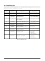
1
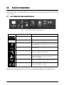
ExpressCube 250
™
Dimensioning System
User Manual
To be the best by every measure
115837
Contents
About This Manual ................................................................................................................................... 1
1.0
Introduction.................................................................................................................................. 1
1.1 Specifications . . . . . . . . . . . . . . . . . . . . . . . . . . . . . . . . . . . . . . . . . . . . . . . . . . . . . . . . . . . . . . . . . . . 1
2.0
Equipment Setup.......................................................................................................................... 2
2.1 Unpacking . . . . . . . . . . . . . . . . . . . . . . . . . . . . . . . . . . . . . . . . . . . . . . . . . . . . . . . . . . . . . . . . . . . . . 2
2.2 Location and Placement. . . . . . . . . . . . . . . . . . . . . . . . . . . . . . . . . . . . . . . . . . . . . . . . . . . . . . . . . . . 2
2.3 Opening and Securing the Back Sensor Array . . . . . . . . . . . . . . . . . . . . . . . . . . . . . . . . . . . . . . . . . . 2
3.0
Electrical Connections ................................................................................................................ 3
3.1
3.2
3.3
3.4
3.5
3.6
3.7
3.8
4.0
Rear Connecting Panel Layout Summary . . . . . . . . . . . . . . . . . . . . . . . . . . . . . . . . . . . . . . . . . . . . . .
USB Connection . . . . . . . . . . . . . . . . . . . . . . . . . . . . . . . . . . . . . . . . . . . . . . . . . . . . . . . . . . . . . . . .
Connection of a Handheld Bar Code Scanner . . . . . . . . . . . . . . . . . . . . . . . . . . . . . . . . . . . . . . . . . .
Connection settings for hand scanners. . . . . . . . . . . . . . . . . . . . . . . . . . . . . . . . . . . . . . . . . . . . . . . .
Printer Connection . . . . . . . . . . . . . . . . . . . . . . . . . . . . . . . . . . . . . . . . . . . . . . . . . . . . . . . . . . . . . . .
Connection of the Ethernet LAN (Option) . . . . . . . . . . . . . . . . . . . . . . . . . . . . . . . . . . . . . . . . . . . . . .
External Device Ports . . . . . . . . . . . . . . . . . . . . . . . . . . . . . . . . . . . . . . . . . . . . . . . . . . . . . . . . . . . .
Power Adapter Connection . . . . . . . . . . . . . . . . . . . . . . . . . . . . . . . . . . . . . . . . . . . . . . . . . . . . . . . .
3
4
4
4
4
5
5
5
Selecting User Control................................................................................................................. 6
4.1 ExpressCube Controller . . . . . . . . . . . . . . . . . . . . . . . . . . . . . . . . . . . . . . . . . . . . . . . . . . . . . . . . . . . 6
4.2 Computer Control . . . . . . . . . . . . . . . . . . . . . . . . . . . . . . . . . . . . . . . . . . . . . . . . . . . . . . . . . . . . . . . 6
5.0
SizeIt™ Software Installation ..................................................................................................... 7
5.1 Minimum Computer Requirements . . . . . . . . . . . . . . . . . . . . . . . . . . . . . . . . . . . . . . . . . . . . . . . . . . . 7
5.2 Software Installation . . . . . . . . . . . . . . . . . . . . . . . . . . . . . . . . . . . . . . . . . . . . . . . . . . . . . . . . . . . . . . 7
5.3 Running the Software . . . . . . . . . . . . . . . . . . . . . . . . . . . . . . . . . . . . . . . . . . . . . . . . . . . . . . . . . . . . . 7
6.0
Power-Up ..................................................................................................................................... 8
6.1 Initial Power-up System Check . . . . . . . . . . . . . . . . . . . . . . . . . . . . . . . . . . . . . . . . . . . . . . . . . . . . . . 8
7.0
User Programming ....................................................................................................................... 9
7.1
7.2
7.3
7.4
Using the ExpressCube Controller Keypad for Programming . . . . . . . . . . . . . . . . . . . . . . . . . . . . . . .
Using the PC running SizeIt™ for Programming . . . . . . . . . . . . . . . . . . . . . . . . . . . . . . . . . . . . . . . . .
Using the PC running a Third Party Software for Programming . . . . . . . . . . . . . . . . . . . . . . . . . . . . . .
Main Programming Menu . . . . . . . . . . . . . . . . . . . . . . . . . . . . . . . . . . . . . . . . . . . . . . . . . . . . . . . . . .
7.4.1
7.4.2
7.4.3
7.4.4
8.0
9
9
9
9
Alter Dimensional Weight [DIM] Factors . . . . . . . . . . . . . . . . . . . . . . . . . . . . . . . . . . . . . . . . . . . . . . . . . 9
Manual / Automatic Operation. . . . . . . . . . . . . . . . . . . . . . . . . . . . . . . . . . . . . . . . . . . . . . . . . . . . . . . . 9
Adjust Beep Duration . . . . . . . . . . . . . . . . . . . . . . . . . . . . . . . . . . . . . . . . . . . . . . . . . . . . . . . . . . . . . 10
Set Device Number . . . . . . . . . . . . . . . . . . . . . . . . . . . . . . . . . . . . . . . . . . . . . . . . . . . . . . . . . . . . . . . 10
Operation.................................................................................................................................... 11
8.1
8.2
8.3
8.4
Main unit LED indicators. . . . . . . . . . . . . . . . . . . . . . . . . . . . . . . . . . . . . . . . . . . . . . . . . . . . . . . . . .
Operation with Third Party Control Software . . . . . . . . . . . . . . . . . . . . . . . . . . . . . . . . . . . . . . . . . . .
Preparation for Measurements . . . . . . . . . . . . . . . . . . . . . . . . . . . . . . . . . . . . . . . . . . . . . . . . . . . . .
Zeroing the ExpressCube 250 . . . . . . . . . . . . . . . . . . . . . . . . . . . . . . . . . . . . . . . . . . . . . . . . . . . . .
11
11
12
12
Technical training seminars are available through Rice Lake Weighing Systems.
Technical training seminars are available through Rice Lake Weighing Systems.
Course
datescan
canbe
beviewed
viewed
www.ricelake.com/training
Coursedescriptions
descriptions and
and dates
at at
www.ricelake.com/training
ororobtained
by
calling
715-234-9171
and
asking
for the
training
department.
obtained by calling 715-234-9171 and asking for the
training
department.
© 2010 Rice Lake Weighing Systems. All rights reserved. Printed in the United States of America.
Specifications subject to change without notice.
Rice Lake Weighing Systems is an ISO 9001 registered company.
Version 1.0, September 2010
i
8.5 Placement of Box for Measurement . . . . . . . . . . . . . . . . . . . . . . . . . . . . . . . . . . . . . . . . . . . . . . . . .
8.6 Verifying That the Parcel is Ready to Measure . . . . . . . . . . . . . . . . . . . . . . . . . . . . . . . . . . . . . . . . .
8.7 ExpressCube Controller Quick Setup Guide. . . . . . . . . . . . . . . . . . . . . . . . . . . . . . . . . . . . . . . . . . .
8.8 Programming Dimensional Weight (DIM) Factors . . . . . . . . . . . . . . . . . . . . . . . . . . . . . . . . . . . . . . .
8.9 ExpressCube Controller Display. . . . . . . . . . . . . . . . . . . . . . . . . . . . . . . . . . . . . . . . . . . . . . . . . . . .
8.10 Dimensional Weight and the Greater Weight Indicator . . . . . . . . . . . . . . . . . . . . . . . . . . . . . . . . . .
8.11 Acquiring the Measurement Data (Manual Operation) . . . . . . . . . . . . . . . . . . . . . . . . . . . . . . . . . . .
8.12 Manual (Acquire & Send / Print) Operation . . . . . . . . . . . . . . . . . . . . . . . . . . . . . . . . . . . . . . . . . . .
8.13 Automatic (Acquire & Send / Print) Operation . . . . . . . . . . . . . . . . . . . . . . . . . . . . . . . . . . . . . . . . .
8.14 Using the ExpressCube 250 as a Weigh Scale Only . . . . . . . . . . . . . . . . . . . . . . . . . . . . . . . . . . . .
9.0
12
12
13
14
14
15
15
16
16
16
Maintenance .............................................................................................................................. 18
9.1 Cleaning (Excluding the Sensor Lenses). . . . . . . . . . . . . . . . . . . . . . . . . . . . . . . . . . . . . . . . . . . . . . 18
9.2 Cleaning the Sensor Lens . . . . . . . . . . . . . . . . . . . . . . . . . . . . . . . . . . . . . . . . . . . . . . . . . . . . . . . . 18
9.3 Replacing the Sensor Lens . . . . . . . . . . . . . . . . . . . . . . . . . . . . . . . . . . . . . . . . . . . . . . . . . . . . . . . 18
10.0
Troubleshooting ......................................................................................................................... 19
10.1 Unit Will Not Power Up. . . . . . . . . . . . . . . . . . . . . . . . . . . . . . . . . . . . . . . . . . . . . . . . . . . . . . . . . .
10.2 LCD Display is Not Working . . . . . . . . . . . . . . . . . . . . . . . . . . . . . . . . . . . . . . . . . . . . . . . . . . . . . .
10.3 PC Controller SizeIt™ is Not Working. . . . . . . . . . . . . . . . . . . . . . . . . . . . . . . . . . . . . . . . . . . . . . .
10.4 Maintenance Codes . . . . . . . . . . . . . . . . . . . . . . . . . . . . . . . . . . . . . . . . . . . . . . . . . . . . . . . . . . . .
11.0
19
19
19
20
Calibration Procedure................................................................................................................ 21
11.1 Calibration Weight . . . . . . . . . . . . . . . . . . . . . . . . . . . . . . . . . . . . . . . . . . . . . . . . . . . . . . . . . . . . . 21
11.2 Procedure . . . . . . . . . . . . . . . . . . . . . . . . . . . . . . . . . . . . . . . . . . . . . . . . . . . . . . . . . . . . . . . . . . . 21
12.0
Appendix: Dimensional Weight & DIM FACTOR......................................................................... 22
12.1 The Importance of Volume and Weight of Cargo for Transportation . . . . . . . . . . . . . . . . . . . . . . . .
12.2 Dimensional (Volume) Weight . . . . . . . . . . . . . . . . . . . . . . . . . . . . . . . . . . . . . . . . . . . . . . . . . . . . .
12.3 DIM Factor (Dimensional Weight Factor). . . . . . . . . . . . . . . . . . . . . . . . . . . . . . . . . . . . . . . . . . . . .
12.4 Using DIM Factor (Dimensional Weight Factor) . . . . . . . . . . . . . . . . . . . . . . . . . . . . . . . . . . . . . . . .
12.5 Dim Factor Conversion Between in3/lb and cm3/kg . . . . . . . . . . . . . . . . . . . . . . . . . . . . . . . . . . . .
22
22
22
22
23
Hardware Warranty Statement .............................................................................................................. 24
Rice Lake continually offers web-based video training on a growing selection
of product-related topics at no cost. Visit www.ricelake.com/webinars.
ii
ExpressCube 250 User Manual
About This Manual
Authorized distributors and their employees
can view or download this manual from the
Rice Lake Weighing Systems distributor
site at www.ricelake.com.
This manual is provided for the use of trained and
qualified installers of dimensioning systems, and
represents the correct, safe and recommended
methods for installing and using the ExpressCube
250™.
1.0
Introduction
The ExpressCube 250 will quickly and accurately dimension and weigh cuboidal packages. The ExpressCube 250
will calculate dimensional weight based on the acquired measurements and preprogrammed factors. The user can
pre-program four factors that can be selected to calculate dimensional weight.
The ExpressCube 250 can record package details using an optional handheld scanner. The measurements,
dimensional weight, and, packaged details recorded from the hand scanner can be printed, read by user software
for instant processing or sent to a central server for further processing.
1.1
Specifications
Physical Characteristics
Dimensions: Inches
25.7 x 30 x 49.5 [L x W x H]
Dimensions: Centimeters
63.5 x 76 x 126 [L x W x H]
Weight (lbs) / (kg)
70 / 23
Operating Environment
14 to 104 F (-10 to 40 C) @ 0 - 90 % Humidity
Imperial Measurements
Max Dimensional Capacity (in)
23.8 x 25.8 x 37 [L x W x H]
Resolution/Min Dimensional (in)
0.2 / 2.4
Maximum Weight (lb)
70
Weight Resolution (lb)
0.1
Metric Measurements
Max Dimensional Capacity (cm)
60 x 65.5 x 94 [L x W x H]
Resolution/Min Dimensional (cm)
0.5 / 6.0
Maximum Weight (kg)
30
Weight Resolution (kg)
0.05
Features
Standard
Printer Port (RS-232)1
Hand Scanner Port (RS-232)2
USB Computer Port3
Optional
SizeIt™ Software
ExpressCube controller
ExpressCube customer display
Ethernet LAN
Table 1-1. ExpressCube 250 Specifications 1Printer not included; 2Hand Scanner not included; 3Computer not included
Introduction
1
2.0
2.1
Equipment Setup
Unpacking
The ExpressCube 250™ is shipped with the back of
the unit folded onto the platform. Carefully remove
the unit from the packing material and place the unit
in the final location prior to removing the shipping
brackets that secures the back to the top platform.
2.3
Opening and Securing the Back
Sensor Array
Refer to the diagram below to raise and secure the
back sensor array from the shipping / storage position.
Inspect the device before starting the procedure to
ensure that all bindings and/or shipping restraints have
been removed.
Figure 2-1. Unit Prepped for Shipping or Storage
Unscrew the leveling feet until approximately
one-half inch is extended from the bottom of the unit.
This will allow maximum flexibility in leveling the
unit.
The ExpressCube 250 may be provided with optional
display and connecting hardware. It is important to
review the equipment list provided in the shipping
container to ensure that all items have been removed
prior to disposal of the shipping container.
NOTE: With the protective shipping brackets removed,
care must be taken not to subject the folded back
assembly to any twisting or impacts that could harm the
hinge assembly.
2.2
Location and Placement
Refer to “Specifications” on page 1 to obtain the
outside dimensions of this model of ExpressCube 250.
This unit should be placed on a countertop or table
that has a surface area that is equal or greater to the
physical dimensions referred to in the specifications.
It is important for accurate weight measurements that
the surface is reasonably level, flat and stable.
Ensure that the area selected for the ExpressCube 250
is free from objects that could touch the unit and that
there is adequate space to place and measure packages
without obstruction.
The ExpressCube 250 should be located within four
feet of a power source. Verify with the specifications
and the power adapter shipped that the power source
a n d t h e E x p re s s Cu b e 2 5 0 p o we r a d ap t e r a r e
compatible.
2
ExpressCube 250 User Manual
Figure 2-2. Opening and Securing Unit
(A) Carefully lift up the rear sensor panel 90 degrees
to the surface of the platform until the holes at the rear
of both parts of the assembly line up.
(B) Insert the supplied four locking bolts into the back
assembly and tighten.
NOTE: It is important to put the locking bolts in without
cross threading. Although the back assembly requires
little effort to be held in place, it is recommended that one
person hold the back sensor panel in place while a
second person installs the locking bolts.
3.0
Electrical Connections
The ExpressCube 250™ is designed such that there is space to connect and run the cables from the rear connector
panel. Do not use this space to bunch and store excess cable as the movement of the platform could be restricted
by cable contact.
3.1
Rear Connecting Panel Layout Summary
Figure 3-1. Rear Connecting Panel Layout Summary
Symbol
* (unmarked)
Function
Description
Power Switch
Switches unit ON / OFF
Calibration
*Authorized Personnel Only* Removal or damage to the
calibration seal voids certification approvals
Power Adapter
The universal power adapter includes 4 power connections and
has the following world safety approvals: UL / ULC, CE, PSE,
BS, GS, FCC, SAA
USB
This USB port can be used by a local PC to Operate and collect
data from the unit.
Hand Scanner
Connect to handheld scanner (not supplied).
The port is a male RS-232 serial interface.
Printer
RS-232 male port provides ASCII data output for either a printer
or direct data logging onto a hard drive via a local PC
application (not supplied).
LAN
10Base-T Ethernet port (optional). Permits remote data
collection onto centralized servers for billing, accounting etc.
Ideal for machines in warehouse locations.
External Devices
These connectors are used to connect external devices such
as the customer display or control box.
Table 3-1. Rear Panel Layout Descriptions
NOTE: Connect all the appropriate connectors prior to connecting the power adapter and activating the device.
Electrical Connections
3
3.2
USB Connection
The ExpressCube 250 series of dimensioning devices
are equipped with a USB connection to interface to a
local computer. The USB connection allows the
computer to control and capture data from the
dimensioning device. The USB is fully compatible
with USB 2.0 computer ports.
Connect the cable as indicated in Figure 3-2.
The ExpressCube 250 unit has programming options
that can utilize the trigger of the handheld scanner to
activate data collection and processing. For more
details, refer to “User Programming” on page 9
3.4
Connection
scanners
settings
for
hand
Connection port
RS-232
Baud rate
9600
Parity
None
Data bits
8
Stop bit
1 and add a suffix of a CR LF (Carriage
Return Line Feed)
Computer USB port and connector
ExpressCube 250 USB port and connector
Table 3-2. Connection Settings for Hand Scanners
3.5
Figure 3-2. USB Connection
NOTE: SizeIt™ software must be installed on the
computer before the USB interface can be used. Refer to
the “SizeIt™ Software Installation” on page 7 for more
details.
3.3
Connection of a Handheld Bar Code
Scanner
Printer Connection
The ExpressCube 250 is equipped with a female
RS-232 serial printer port. The port is activated when
the unit has acquired data through a successful
measurement. Upon receiving a Print command, the
printer port will deliver the data in an ASCII format
that is terminated with a line feed and carriage return.
The RS-232 connector should be securely connected
to the appropriate connector on the ExpressCube 250.
The ExpressCube 250 has a dedicated male RS-232
serial port for use with a handheld bar code scanner.
NOTE: Handheld scanner not supplied.
The RS-232 connector should be securely connected
to the appropriate connector on the ExpressCube 250.
Figure 3-4. Star SP-300 Printer
NOTE: The ExpressCube 250 has been specifically set up
using the Star SP-300 Series ASCII model. While most
ASCII RS-232 printers follow virtually identical data
formats, the user is responsible to assure their selected
printer is compatible to the Star-300 series format.
Figure 3-3. Sample RS-232 Hand Scanner
NOTE: There are two RS-232 connectors on the
connector panel but each one serves different purposes.
Be sure to use the connector identified for the hand
scanner.
4
ExpressCube 250 User Manual
3.6
Connection of the Ethernet LAN
(Option)
The ExpressCube 250 can be equipped with an active
10 Base T Ethernet LAN port. The user can send
acquired measurement data to a remote server for
recording and/or billing purposes. The LAN device is
only used to record package data and cannot be used
to control the ExpressCube 250 functions.
The LAN connector is a standard RJ-45 connector.
The LAN port configuration is programmed through
the USB connector using the ExpressCube 250
maintenance software. The port configuration is
recorded on non-volatile memory and will remain
until reprogrammed through the USB connector.
The ExpressCube 250 external device ports use RJ-11
four wire connectors. Place or mount the device to be
connected in the location that it will be used. Insert the
RJ connector until an audible click is heard. Carefully
route the cable and insert the RJ-11 connector into
either one of the two ExpressCube 250 external device
ports.
The RJ-11 is a popular jack used by
anufacturers for a variety of
Warning m
different devices and purposes. Do not
insert any other manufactured device equipped with a
RJ-11 into the ExpressCube 250 device port. The
attempted use of this RJ-11 port for any device other
than a ExpressCube 250 device can cause internal
damage and void the warranty.
The ExpressCube 250 external device ports provide
low voltage power to operate the circuits and backlit
LCD displays of the external devices. Care should be
taken to ensure that no foreign objects are inserted
into these ports.
3.8
Figure 3-5. RJ-45 Connector
NOTE: A physical LAN port is included on the rear
connector panel of all ExpressCube 250 units but the
necessary support hardware & software is an option that
must be ordered from the factory at the time of original
purchase.
3.7
Power Adapter Connection
After connecting the appropriate connectors as
detailed in Section 3.1 to 3.7, insert the power adapter
plug into the ExpressCube 250 rear connector panel.
External Device Ports
The ExpressCube 250 external ports are high-speed
data and power ports that are used to connect to
optional ExpressCube 250 equipment. There are two
external device ports on the rear connector panel. The
two ExpressCube 250 external devices supported by
these ports are the control unit and the ExpressCube
customer display unit as illustrated in Figure 3-6.
Figure 3-7. Power Adapters
The cable from the rear of the unit to the adapter
should be free from obstruction and located to prevent
accidental removal from ExpressCube 250 or the
outlet. Securely connect the power plug into an
electrical outlet.
NOTE: Use only ExpressCube 250 power adapters with
the unit. The power adapter must have unrestricted
airflow around it. Do not wrap or enclose the power
adapter.
LCD Controller
Wall Mount
LCD Controller
Desk Mount
Customer
Display
Figure 3-6. External Devices
The ExpressCube controller has a reversible mounting
plate that allows the controller to be converted from a
desk mount (as shipped) to a wall mount. To change
the configuration, remove the four screws holding the
bracket. Rotate the mounting bracket 180 degrees and
secure with the same four screws.
Electrical Connections
5
4.0
Selecting User Control
The ExpressCube 250™ system must have an operator controller to perform the measurement functions. The
system can be controlled either by a desktop computer using the USB interface or by using the ExpressCube
controller. If a display is required to monitor the operation, it is recommended to use the ExpressCube customer
display.
4.1
ExpressCube Controller
The use of the ExpressCube controller only requires the appropriate electrical connection as described in the
section “External Device Ports” on page 5. The installation of the SizeIt™ software is not required. Proceed to
“Power-Up” on page 8 of this manual.
4.2
Computer Control
The use of a computer to control the ExpressCube 250 system will require the installation and use of the SizeIt
software. Connect the USB cable as previously described and follow the instructions outlined in the “SizeIt™
Software Installation” on page 7.
NOTES:
In this manual, the term control panel will reference the device used to control the ExpressCube 250 system. For
example, ExpressCube controller or local computer running SizeIt™ software.
When the ExpressCube controller is used to control the ExpressCube 250, the USB port is still active and can be used
by a trained technical or administration personnel to service the unit.
6
ExpressCube 250 User Manual
5.0
SizeIt™ Software Installation
The SizeIt™ software allows a local computer to operate and gather data from the ExpressCube 250™ with the
USB port. This software must be installed and the USB connected prior to powering-up the ExpressCube 250.
The software is not required if the ExpressCube controller is used to control the countertop unit.
5.1
Minimum Computer Requirements
•
•
•
•
•
Minimum 512 meg of available RAM
Pentium IV or better @ 2.0 GHz or better
Windows XP operating system
CD-ROM drive
Java version 1.5.0_06 or later
1.
2.
3.
4.
5.
Close down all applications currently running on the PC.
Insert the CD program disk into the CD-ROM drive of the computer.
Click the Windows 'START' button and select 'RUN'
Use the browse key to locate and select the 'set-up' file on the CD-ROM drive
Run the selected file.
5.2
Software Installation
NOTE: If you encounter recurring problems with the operation of the program, un-install Size-It and re-install.
The person installing the software should have the appropriate system permissions to install the software, this
will vary for the system & location, and this can be especially critical for Windows XP operating systems.
5.3
Running the Software
Use either the Start/Program or Desktop menus to begin the SizeIt™ program. The program will open the control
page as shown in Figure 5-1. Select the highest "com number" on the drop menu to engage the USB. Choice
shown as 'com 7' in Figure 5-1.
Figure 5-1. SizeIt™ Control Page
The USB port will remain off when the ExpressCube 250 unit is not powered. The 'Set-up' key will not work until
communications is established on the USB link.
SizeIt™ Software Installation
7
6.0
Power-Up
Locate and activate the power switch located on the rear panel. The ExpressCube 250™ must not have anything
on the platform when the power is switched on. Almost instantly, the power [RED] indicator LED will begin to
flash and then remain lit. During the brief time that the LED is flashing, power has been applied to the main
computer and it has started its program initiation. The steady LED indicates that the power is on, the sensors are
calibrated and the main computer is operating properly.
NOTE: The four indicator LEDs on the front of the ExpressCube 250 are intended to give the user a quick summary of
the current operation of the unit. These LEDs are controlled by the measuring device and are not affected by the
controller, including third party software. Always refer to the control panel display for detailed operational status.
6.1
Initial Power-up System Check
The motherboard enters a self-diagnostic routine in which errors are reported in a diagnostic log. The results of
the diagnostic routine contain a summary of the polling the different subsystems of the ExpressCube 250
This section just briefly describes the system checks carried out by the motherboard as it is powered up. It is
carried out almost instantly and has no visible effect on the operation of the unit.
Function
Description
System Check
The system verifies the proper operation of on-board components.
Configuration
Each power up cycle, the motherboard polls and assigns addresses to the Integrated
Transceiver Array which performs the package measurements.
Load Cell
The motherboard verifies the operation of the load cells and programs the filters used in
the digital interface.
Table 6-1. System Checks
Any irregularities are recorded as maintenance codes and can only be accessed by a software header in the
motherboard.
NOTE: The control panel will be ready for operation after the system check is performed within a few milliseconds of
power-up. If the display or system does not appear to be functioning, see “Troubleshooting” on page 19. DO NOT
ATTEMPT TO OPEN THE SYSTEM.
8
ExpressCube 250 User Manual
7.0
User Programming
The ExpressCube 250™ has a simple programming
menu that allows the user to program the following
characteristics:
• Program dimensional weight factors.
• Handheld bar code scanner Acquire & Print
synchronization.
• Adjust audible (beep) warning characteristics.
• Set device number.
Generally the user programming is set once and rarely
requires adjustment. All programmed selections are
stored and will remain until changed through the user
programming.
User programmed features and data is stored on
non-volatile memory and will be retained even if the
ExpressCube 250 is not powered.
7.1
Using the ExpressCube Controller
Keypad for Programming
The ExpressCube controller keypad has been
designed to easily make adjustments using the
user-programming feature. Respond on the numeric
keys as directed by the display to make a menu
selection.
Use the UNITS button to toggle between in/lb and cm/
kg. Use the ACQUIRE button to enter a typed
numerical value.
7.2
Using the PC running SizeIt™ for
Programming
The programming menu can be easily accessed from
the PC running SizeIt™ software program by clicking
the Settings [Prog] key using the mouse cursor. All
menu selections can be selected by the mouse and
normal PC keyboard functions can be used to edit data
entries.
7.3
Using the PC running a Third Party
Software for Programming
The ExpressCube 250 has an API interface which
allows third party software to operate, acquire data
and utilize the user program feature set. Refer to the
manufacturer's instruction on the use of programming
features with the third party software.
Third party software will have access
all data from the ExpressCube 250
Warning to
data including measurements, units,
dimensional weight, dimensioning factor and
handheld scanner codes; however, the software
manufacturer may use the ExpressCube 250 to
measure, weigh and collect handheld scanner codes
o n l y. I f t h e th i rd p a r ty s o ft w a r e d e t e r m i n e s
dimensional weight, only accessing the third party
software can change dimensional weight factors.
7.4
Main Programming Menu
7.4.1
Alter Dimensional Weight [DIM] Factors
Selecting this menu allows the user to review or
change any of the four dimensional factors used by the
ExpressCube 250 computer to calculate dimensional
weight.
Sub-menu
1. (Dim Factor) [Units]
2. (Dim Factor) [Units]
3. (Dim Factor) [Units]
4. (Dim Factor) [Units]
5. BACK
Select the dim (dimensional weight) factor that you
wish to change and verify the correct units before
entering the new value.
The dimensional weight factors can only have four
digits with the last digit representing units or tenths
(000.0 to 9999). Any entry of four or less digits will
be assumed whole numbers unless a decimal is used.
The maximum dim factor setting is 276 in3/lb.
The Dim Factors are displayed in the units that they
were originally input but the ExpressCube 250
computer will convert the dimensional weight factors
to match the units that are used.
The dimensional factor displayed and output from the
unit will always match the units that the
measurements were taken.
7.4.2
Manual / Automatic Operation
This selection provides an option for an automatic
recording of the measurement data after the data is
collected. The automatic operation can significantly
speed the measurement process and is used when
there is no requirement to review acquired
measurements before recording them.
User Programming
9
Manual Operation
If the ExpressCube 250 is in a ready state to record the
measurement, the user will press the Acquire key or
(if equipped) the trigger of the handheld scanner. The
acquired measurement data will be displayed but the
user must activate the SEND / PRINT key to record
the data. Removal of the package from the platform
will clear any acquired measurements and prepare the
device for a new measurement sequence.
Automatic Operation
If the ExpressCube 250 is in a ready state to record the
measurement, the user will press the trigger of the
handheld scanner (if equipped). The ExpressCube 250
will record the measurements and automatically send
the acquired data with the bar code as if the SEND
button had been pushed. All acquired data will remain
in the display until the parcel is removed from the
ExpressCube 250 platform.
Sub-menu
MANUAL / AUTOMATIC OPERATION
1. MANUAL <SELECTED>
2. AUTOMATIC
3. GO BACK
4. EXIT
Press the appropriate number to select the desired
operation mode. The current selection will be
indicated by the <SELECTED> beside it. After
verifying the correct selection, use EXIT function to
return to the main menu.
7.4.3
Adjust Beep Duration
This selection will permit the user to adjust or turn off
the warning beep tone.
Sub-menu
SELECT 0-9
CURRENT SELECTION 6
Enter a digit from 0 (off) to 9 to set the audible tone.
The current selection will be updated and the selection
confirmed in large format. After the confirmation, the
program will exit to the main menu.
7.4.4
Set Device Number
This selection allows the user to set a device number
for the ExpressCube 250. The device number is sent
with each data message of acquired data. This device
number can be used to track a box through a facility.
10
ExpressCube 250 User Manual
Sub-menu
CURRENT DEVICE NUM XXX (000-999)
If device number requires change from the current
number, type in the three-digit new device number.
When the new device number is confirmed on the
display, the program will automatically exit to the
main menu.
Pressing the PROG key will exit the menu without
changing the device number.
8.0
Operation
The ExpressCube 250™ is a very accurate
Multi-Dimensional Measuring Device (MDMD) that
is capable of measuring cuboidal (rectangular/square)
boxes with great precision. The ExpressCube 250 has
built in controls to prevent erroneous readings that
cannot be altered by third party software control. Even
with these built in controls, the user must exercise
care to follow these guidelines:
• Boxes cannot exceed the dimension and
weight listed in the specifications.
• Boxes must be cuboidal (for example,
rectangular or square).
• Severely damaged packages or packages
covered by excessive mud or ice can cause
errors for both dimensions and weight.
• Both the platform and the package being
measured must be free from physical contact
with surrounding objects.
• Place objects on the platform. Do not drop
packages onto the platform.
NOTE: Keep the platform clean and free of dust build up
to ensure optimum operating performance.
8.1
Main unit LED indicators
The main unit LED indicators are a set of four LEDs
mounted on the front of the main platform of the
ExpressCube 250. They give an accurate status of the
ExpressCube 250 main computer and are unaffected by
third party software.
Color
Definition
Red - Power
A steady illumination
indicates that the unit has
power.
Yellow - Valid Dimension
A steady illumination
indicates that the unit has
measured a parcel placed
on the platform.
Green - Valid Weight
A steady illumination
indicates that the unit has
weighed a parcel placed
on the platform.
Blue - Zero
A steady illumination
indicates that the unit is in
a zero (no-load) condition.
Table 8-1. Description of LED Colors
NOTE: The unit will not attempt any new measurement
until the unit has reached a zero condition after the
removal of the previous package. The Yellow and Green
LED indicators will remain in the ACQUIRED state until a
zero condition is achieved after the last recorded
measurement.
8.2
Operation with Third Party Control
Software
If this ExpressCube 250 is used with third party
software (not an ExpressCube 250 control panel), it is
important that the user studies the documentation that
is supplied with the third party software.
It is not possible for the third party software to affect
the integrity of the measurements output from the
ExpressCube 250. The acquired data is output only if
the correct procedures have been followed (zero
condition, etc) and the output data itself is packaged
with all related measurement parameters in the data
packet. However, it can be difficult for the user to
initiate this sequence without a full understanding of
the software being used.
Figure 8-1. Main Unit LED Indicators Location
NOTE: It is recommended that third party software users
read the following operation procedures for the control
panel. The procedure for obtaining a measurement is
identical and helpful points presented in the manipulation
of the package will be useful.
Operation
11
8.3
Preparation for Measurements
The ExpressCube 250 should be powered up and the
ExpressCube 250 control panel display finished the
initial system check. Prior to starting measurements, it
is recommended that the platform and sensors be
wiped with a damp rag to remove any accumulated
dirt and/or debris.
Select the units and dimensional factor (if used) for
measuring the parcel.
8.4
8.5
Placement of Box for Measurement
Place the box to be measured flush against the back of
the ExpressCube 250 such that one side of the box is in
contact with the rear face. The orientation of the box
is arbitrary as long as it:
• Sits over the center array
• Is flush (contact) to the back
• Sits within the guidelines
Zeroing the ExpressCube 250
The ExpressCube 250 will not re cord any
measurements unless the platform has recorded the
Zero condition (weight of the platform in an idle
condition) prior to a package being placed on the
platform. After verifying that the measurement
platform is empty, press the ZERO function button on
the ExpressCube 250 control panel.
The Blue LED under the platform will light and a zero
condition will be indicated by the word ZERO on the
display of the ExpressCube 250 control panel. The
Zero condition display for both of the ExpressCube
250 control panels is show in Figure 8-2.
Figure 8-4. Example of Box Placement
Figure 8-4 shows an example of a box ready for
measurement and indicates how the dimensions will
be recorded.
8.6
Figure 8-2. ExpressCube Controller Display
Figure 8-3. SizeIt™ Display
12
ExpressCube 250 User Manual
Verifying That the Parcel is Ready
to Measure
Once the box is in place, the ExpressCube 250 will
resolve the weight and dimensions. A successful
measurement is indicated by the steady illumination
of the yellow LED (valid dimension) and the green
LED (valid weight) on the front of the platform. The
ExpressCube 250 control panel will also have valid
measurement indicators with the actual measurements
displayed.
If the weight has not been resolved, the problem could
be caused by:
• The box weight exceeds specifications.
Weight will read OVER.
• The ExpressCube 250 was not in a zero
condition prior to the box placement on the
platform.
• The ExpressCube 250 is undergoing vibrations
or movement that prevent weight resolution.
If the dimensions cannot be resolved, all dimensions
will read N/A. If a cuboidal package is placed within
the guidelines and there is not a valid dimension
obtained, the problem could be caused by:
• The box dimension does not fall between the
minimum and maximum the specifications.
• The box is not flush against all three
dimensional arrays.
• There is excessive dirt or an object blocking
the measuring arrays.
8.7
ExpressCube
Setup Guide
Controller
Quick
1. Carefully remove the ExpressCube controller
from the packing material and place the unit
in the final location.
NOTES:
If the unit is unable to resolve a valid dimension, it will
behave as a weigh scale. In this condition, acquiring a
measurement will only record the weight and a scan code
(optional).
If the unit is equipped to dimension only, the unit will not
record a measurement unless a valid dimension is
obtained.
The ready to acquire condition (valid measurements)
display for both of the ExpressCube 250 control panel
is shown in Figure 8-5 and 8-6.
Figure 8-7. ExpressCube Controller
2. Place the device to be connected in the
location that it will be used.
3. Carefully route the cable and insert the RJ-11
connector into either one of the two
ExpressCube 250 external device ports.
Figure 8-5. ExpressCube Controller Display
Figure 8-8. External Device Ports
4. The control panel will be ready for operation
after the system check is performed within a
few milliseconds of power-up.
Figure 8-6. SizeIt™ Display
Figure 8-9. Control Panel
Operation
13
8.8
Programming Dimensional Weight
(DIM) Factors
Selecting the program button (PROG) allows the user
to review or change any of the four stored DIM factors
used by the ExpressCube 250 computer to calculate
dimensional weight.
Select the DIM factor that you wish to change and
verify the correct units of measure (Metric or
Imperial) before entering the new value.
Accept New DIM Factor “xxx.x”
1. Select Yes or No
The dimensional weight factors can only have four
digits with the last digit representing units or tenths
(000.0 to 9999). Any entry of four or less digits will
be assumed whole numbers unless a decimal is used.
The maximum dim factor setting is 276 in3/lb.
8.9
ExpressCube Controller Display
LCD display functions are highlighted here to
acquaint you with the measurement process.
Gross weight is shown with one decimal figure, which
conforms to the current measure unit specification.
Figure 8-11. Gross Weight Shown
Figure 8-10. Control Panel
Select an Option
The word "RES" will appear while the system is
resolving a valid weight and/or a valid dimension.
1. To program, press and hold PROG for 1
second.
2. Change DIM Factor.
3. Change Scanner Trigger.
4. Change Device Number.
5. Exit (or Press PROG).
Select the Unit Type
1. To program, press and hold PROG for 1
second.
NOTE: Press buttons firmly when selecting.
2.
3.
4.
5.
Metric
Imperial
Go Back
Exit (or Press PROG)
Figure 8-12. System Resolving a Valid Weight Menu
After a box has been placed on the platform for
measurement, the "Acquire" button can be pressed at
any time while the system is still in the "RES"
(resolve stage). This allows faster weight and
dimension acknowledgement and eliminates the need
to wait for the "Valid" numbers to settle in first, as
required previously.
Select the Imperial DIM Factor to Change
1. To program, press and hold PROG for 1
second.
2. 154.9
3. 192.0
4. 145.0
5. 105.1
6. Go Back
7. Exit (or Press PROG)
Input New DIM Factor to Replace Current Number
1. To program, press and hold PROG for 1
second.
2. Enter new number.
14
ExpressCube 250 User Manual
Figure 8-13. From Resolve Stage to Acquire Menus
A very important addition to the capability of the new
updated diagnostic version enables the operator to
perform the sensor array bank calibration. This
procedure can be a valuable addition to a regular
maintenance program as the calibration will help the
sensor measurements to run at peak performance and
correct any unexpected aberrations on the lens that
can affect accurate readings. To access the Calibration
DIM Banks feature, press "PROG" on the keypad,
then select number "5" and then follow the
instructions on the display.
8.11 Acquiring the Measurement Data
(Manual Operation)
Figure 8-14. Calibrate DIM Banks Menu
8.10 Dimensional Weight and
Greater Weight Indicator
the
The ExpressCube 250 is equipped with the capability
to measure both dimensions and weight will use these
measurements to calculate Dimensional Weight based
on the user selected Dim Factor. It is important to
realize that Dimensional Weight is meaningless unless
the Dim Factor used to obtain it is known. For this
reason, Dimensional Weight that is acquired will be
recorded with the Dim Factor used to calculate it.
Similarly, the Dimensional Weight and Dim Factor
will be sent in the data that accompanies the measured
data and scan code (optional).
To record the measurement of the box on the
ExpressCube 250, activate the ACQUIRE button on
the ExpressCube 250 control panel. Alternatively (if
equipped), the handheld scanner will activate the
Acquire sequence while reading the bar code on the
package. The acquired data will be displayed on the
ExpressCube 250 control panel display.
If the data is not recorded, an audible beep will be
heard. See Section 8.10 on page 15 and verify that the
box is properly positioned for measurement.
NOTES:
If the box is removed from the platform without the
SEND/PRINT button activated, the acquired data will be
lost and the unit must return to the zero condition to start
a new measurement.
After a successful measurement is acquired, the valid
measurement indicators both on the front panel of the
main unit and the control panel are held until a new
measurement procedure is started.
Figure 8-16 and 8-17 below display the successful
acquired measurement (ACQD) for both control
panels.
NOTE: Since Dimensional Weight is a calculated weight;
units are not displayed to prevent confusion with actual
weight. Dimensional Weight is always the same units as
actual weight.
The greater weight indicator on the ExpressCube 250
control panel is a visual aid to the user to quickly
identify the greater of measured or calculated
Dimensional Weight. The indicator is not sent with the
acquired data.
The greater weight indicator for each of the
E x p re s s C u b e 2 5 0 c o n t r o l p a n e l i s s h o w n i n
Figure 8-15
Figure 8-16. ExpressCube Controller Display
Figure 8-15. Greater Weight Display
Figure 8-17. SizeIt™ Display
Operation
15
8.12 Manual (Acquire & Send / Print)
Operation
The acquired measurement data can be sent to the
printer and any other devices or ports connected to the
ExpressCube 250 by activating the SEND/PRINT
button on the ExpressCube 250 control panel. The
SEND / PRINT button will only respond once for
every measurement taken.
The ExpressCube 250 will attempt to successfully send
the acquired measurement data through the various
data ports until the ExpressCube 250 returns to a zero
condition. Any measurement data that has not been
sent or printed will be cleared from the transmission
buffer when the ExpressCube 250 is in the zero
condition.
The successful acquired and sent measurement
display for both of the ExpressCube 250 control panels
is shown in Figure 8-18 and 8-19 below.
Figure 8-18. ExpressCube Controller Display
NOTE: The ExpressCube 250 control panel display will
continue to hold the acquired data until the box is
removed.
8.13 Automatic (Acquire & Send / Print)
Operation
This feature can be used when the AUTOMATIC
OPERATION option is selected in the user program.
See Section 7.4.2 on page 9. The ExpressCube 250
must be ready for acquiring a measurement as
described in Section 8.6. To acquire and record the
measurement of the box on the ExpressCube 250, the
handheld scanner will activate the Acquire and SEND
/ PRINT sequence while reading the bar code on the
package. The ExpressCube 250 will receive the data
from the handheld scanner and append it with the
acquired measurement data. The acquired data will be
displayed on the ExpressCube 250 control panel
display.
The ExpressCube 250 will attempt to successfully send
the acquired measurement data through the various
data ports until the ExpressCube 250 returns to a zero
condition. Any measurement data that has not been
sent or printed will be cleared from the transmission
buffer when the ExpressCube 250 returns to a zero
condition.
If the measurement data is not acquired, an audible
beep will be heard. The user should refer to
Section 8.5 and verify that the box is properly
positioned for measurement.
NOTES:
The ExpressCube 250 control panel display will continue
to hold the acquired data until the box is removed.
After a successful measurement is acquired and sent, the
valid measurement indicators both on the front panel of
the main unit and the ExpressCube 250 control panel are
held until a new measurement procedure is started.
16
ExpressCube 250 User Manual
Figure 8-19. SizeIt™ Display
8.14 Using the ExpressCube 250 as a
Weigh Scale Only
The ExpressCube 250 can be used to measure the
weight of non-cuboidal objects or cuboidal objects
that physically exceed the dimensioning specifications
of the machine. This feature allows the user to
determine weight on courier documentation paks, odd
package shapes including shipping cylinders, etc.
Place the package on the ExpressCube 250 platform to
physically limit as much package over-hang as
possible. The ExpressCube 250 will automatically
reconfigure itself as a weigh scale when an object is
detected on the platform that cannot be accurately
dimensioned.
The ExpressCube 250 unit acting as a weigh scale will
indicate N/A on all measurements and calculations
based on dimensional measurements. See Figure 8-20
and 8-21. Only the device number, weight and scan
code (optional) are recorded during the Acquire
sequence.
To acquire and record a weight, use the same
procedure and options as described in the previous
sections for obtaining and recording dimensions.
Figure 8-20. ExpressCube Controller Weight Only Display
Figure 8-21. SizeIt™ Weight Only Display
Operation
17
9.0
Maintenance
The ExpressCube 250™ is a sealed certified device that does not require any internal periodic maintenance. In the
event that the unit has incurred physical damage that may affect the operation of the unit, it should be sent back
to an authorized service center for repair and recalibration.
9.1
Cleaning (Excluding the Sensor Lenses)
To maintain the optimum performance of the ExpressCube 250, the unit should be periodically cleaned to remove
any build-up of dust and dirt. The black metal areas should be cleaned separately from the sensing strips. Use a
damp cloth with a mild detergent and rinse with a clean damp cloth. Hand pumped sprayers can be used. Apply a
non-corrosive cleaner to stubborn areas but care should be exercised to keep spray from the sensor strips.
NOTES:
Do not use any volatile liquids to clean the surface. This is an electronic device and trapped fumes in the enclosure
could be ignited by the electronic circuitry.
Do not use any pressurized liquid source (e.g. water hose, steam jet, etc) to clean the unit.
9.2
Cleaning the Sensor Lens
It is important to keep the sensor lenses clean and free from any debris that may obscure the package from
sensors. Use a soft clean cloth with commercial glass cleaner to clean the surface of the lens.
NOTE: Do not use abrasive or dry cleaners on the lens.
9.3
Replacing the Sensor Lens
If a sensor lens becomes foggy (opaque) from wear, cracked or broken it should be replaced. All three lenses
have a cover to permit safe and quick replacement of the lens. The covers are held on by two screws and the
locations are illustrated below.
Screws
Cover
Lens
Sensor
Lens Removal Points
Sensor Lens Cover
Removal
Figure 9-1. How to Replace the Sensor Lens
18
ExpressCube 250 User Manual
10.0
Troubleshooting
The ExpressCube 250 ™ is a multi-dimensional
precision instrument designed to work in a variety of
working environments. The internal assembly is
sealed to preserve the integrity of this measuring
instrument. There are a number of problems that may
arise that can be addressed without tampering with the
seals which are reviewed in this section along with
problems involving possible parts replacement.
This section addresses problems that are occurring in
lieu of the device being properly installed, cleaned
and operated as per the above sections.
Only authorized technicians may break the seals to
perform repairs on the ExpressCube 250. Unauthorized
personnel breaking the seals for any reason will void
the government certification and possibly void the
warranty on the unit.
10.1 Unit Will Not Power Up
The unit is connected to the power supply that is
connected to power but the operation of the OFF-ON
switch has no affect. The red LED on the front of the
platform is off.
Check (in numerical sequence):
1. Physically verify the connections of the
power adapter to the power outlet and the
power connector.
2. Verify the power outlet by connecting a lamp
or other known operational device.
3. (Technician only) Remove the power adapter
from the ExpressCube 250 and verify that the
voltage to unit is present [15 VDC]. If the
voltage is not present, contact your sales
representative for a new power adapter.
4. Contact your service center to arrange repair
by a qualified service representative.
10.2 LCD Display is Not Working
The LCD display on the ExpressCube controller either
does not display any intelligent characters or cannot
control the ExpressCube 250.
Check (in numerical sequence):
1. Check that the red LED on the front panel of
the unit is steady. If not steady, turn off the
unit and remove power cord for 30 seconds.
Reconnect the power and turn the power ON.
If LED continues to flash, contact your
service center to arrange repair by a qualified
service representative.
2. Physically
check
the
cable
(authentic
ExpressCube 250 part) and the connections to
both the ExpressCube 250 connector panel and
the controller.
3. Switch the connecting cable to the alternative
external connector on the ExpressCube 250
connector panel.
4. (Technician only) Use an Ohm meter to verify
the cable conductivity and visually inspect the
RJ connectors for physical damage.
5. Contact your service center to arrange repair
by a qualified service representative.
10.3 PC Controller SizeIt™ is Not
Working
The SizeIt™ software program running on the PC is
not communicating with the ExpressCube 250.
Check (in numerical sequence):
1. Check that the red LED on the front panel of
the ExpressCube 250 is steady. If not steady,
turn off the unit and remove power cord for
30 seconds. Reconnect the power and turn the
power ON. If LED continues to flash, contact
your service center to arrange repair by a
qualified service representative.
2. Turn off the program in the computer and
remove the USB cable until a tone is heard
from the computer. Put in the USB and wait
for a computer tone again. Restart the SizeIt™
software.
3. If the SizeIt™ program is still indicating that
there is not USB connection; physically check
the USB cable connections to both the
ExpressCube 250 connector panel and the
controller.
4. If the SizeIt™ program is still indicating that
there is not a USB connection, replace the
USB cable.
5. (IT Technician only) Verify proper hardware
and software operation of personal computer
(PC). ExpressCube 250 warranty only relates
to the ExpressCube 250 provided products as
o u t l i n e d i n t h e “ H a r d w a r e Wa r r a n t y
Statement” on page 24.
6. Contact your service center to arrange repair
by a qualified service representative.
Troubleshooting
19
10.4 Maintenance Codes
The ExpressCube 250 has built in diagnostic software programming which will report problems to a maintenance
log. The maintenance will be displayed either as a code or the code related maintenance statement depending on
the maintenance software connected to the access header.
Maintenance
Code
Maintenance
Statement
Comments
01
No platform
Communication
There is no communications coming from
platform
02
USB - No
Communication
There is no communication between the
computer and the device
• Check connection
• Check software installation
03
USB - Bad
Communication
The communication between the
computer and the device has numerous
errors or intermittent
• Check connection
• Check cable
• Authorized Service
04
Scale Unstable
Unable to obtain stable readings from load
cell
• Check the table for vibrations
• Authorized Service
05
Bad length
Communication
There is no / erroneous communications
coming from length array
Authorized Service
06
Bad width
Communication
There is no / erroneous communications
coming from width array
Authorized Service
07
Bad height
Communication
There is no / erroneous communications
coming from height array
Authorized Service
08
Bad Controller
Communication
There is no / erroneous communications
coming from controller
•
•
•
•
Check connections
Check cable
Switch ports
Authorized Service
09
Bad Display
Communication
There is no / erroneous communications
coming from customer display
•
•
•
•
Check connections
Check cable
Switch ports
Authorized Service
Table 10-1. Maintenance Codes
20
ExpressCube 250 User Manual
Troubleshooting
Authorized Service
11.0
Calibration Procedure
Warning Performed by Authorized Personnel Only
The ExpressCube 250™ is factory calibrated and sealed to preserve the integrity of the weight measurements.
Removal of the calibration seal by unauthorized personnel will void government certification of the ExpressCube
250 and could void the warranty.
11.1 Calibration Weight
The ExpressCube 250 must be calibrated using a 50 pound calibrated weight only (25 kg weight where
applicable). Both the platform and calibration weight should be clean before the procedure is started.
11.2 Procedure
1. Move the ExpressCube 250 to permit access to the back panel of the device. It is important that there is
no contact with the platform of the device when the calibration button is accessed or during the
calibration process.
2. Remove the seal protecting the calibration button located on the back panel adjacent to the power switch.
The unit should be powered and in an idle state.
3. Press the calibration button once until the Blue LED on the front panel is flashing. This will set the zero
reference for the calibrated weight.
4. Carefully place the 50 pound calibrated weight on the center of the platform. Allow approximately 5
seconds for the platform to settle.
5. With the calibration weight in place, press the calibration button a second time to record the weight. The
green LED will become steady.
6. Remove the calibration weight and power the unit off and on to lock in the new calibration table.
7. Re-seal the access to the calibration button.
NOTE: If a load cell is damaged from an accidental impact, calibration will not repair or mask the damage. Always
contact your authorized servicing distributor to analyze weighing irregularities with the unit.
Calibration Procedure
21
12.0
Appendix: Dimensional Weight & DIM FACTOR
12.1 The Importance of Volume and
Weight of Cargo for Transportation
12.3 DIM Factor (Dimensional Weight
Factor)
All cargo space involved in transporting goods has
physical limits based on the volume of the cargo and
the weight. Once a cargo has reached a limit in either
volume or weight - the container (trailer, train, plane
or shipping container) is transported. Weight has
traditionally been the measurement which the
transportation costs of individual packaged freight has
been calculated.
The difference in weight and volume costs can be
appreciated if one considered the expense of
transporting a large volume with little weight, for
example a large box of Styrofoam drinking cups.
Transportation companies have recognized these
variables and most have allocated a volume per
weight standard in their billing to capture cargo of
light density.
The DIM factor is a mathematical factor used to
calculate the dimensional weight of an object. The
DIM factor represents the volume of a package
allowed per unit of weight. Although mathematically
related, the DIM factor is different for measurements
in units of inches/pounds and for measurements in
centimeters/ kilograms.
All major courier companies now apply the DIM
Factor to every cuboidal (rectangular/square) parcel
that they handle to determine the dimensional weight.
They then adjust customer invoicing to reflect charges
based on the greater weight between actual weight and
dimensional weight.
Finding a DIM Factor using in/lb
Find the DIM factor if each cubic foot (12"x12"x12")
has a minimum weight allowance of 10 pounds:
12.2 Dimensional (Volume) Weight
The dimensional weight (also known as volume
weight) is the minimum weight that a package a given
size may have that is handled by a carrier. A carrier
may state that any package of one cubic foot
(12"x12"x12") will have a minimum weight
allowance of 10 pounds. If the cubic foot package
actually weighs 8 pounds - it will be invoiced for 10
pounds. This is a minimum weight allowance - if the
cubic foot package weighs 12 pounds - the charges
will be based on 12 pounds.
There are no international or domestic standards
concerning values of d imensional weight. A
significant number of courier companies use the
dimensional weight standard set by the International
Air Transport Association (IATA) but many define
their own dimensional weights.
The value of dimensional weights will probably
change as the nature of shipments change over time.
Organizations such as the International Air Transport
Association (IATA) have produced studies that
suggest the density of packaging is changing as the
commodities become more high tech. As a result the
I ATA i t s e l f h a s a l r e a d y p a s s e d a r e s o l u t i o n
(Resolution 501) to change the IATA dimensional
weight.
22
ExpressCube 250 User Manual
Finding a DIM Factor using cm/kg
Find DIM factor if each cubic meter (100cm x 100cm
x 100cm) has a minimum weight allowance of 200 kg:
12.4 Using DIM Factor (Dimensional
Weight Factor)
The DIM Factor provides a quick determination of the
dimensional weight of any cuboidal package. The best
way to describe this application is by an example of
the application and use of the DIM Factor by a courier
company:
What is the billing rate of a 10"x 12"x 14" package
that weighs 8 lbs by a courier that has a minimum
dimensional weight of 10 lbs per cubic foot (i.e.: DIM
Factor = 172.8 in3/lb)?
The courier company will invoice based on 9.7 lbs the dimensional weight.
NOTE: This is an example. Some courier companies
always round dimensional weight up to the next pound,
which in this sample would make the billing weight 10 lbs.
12.5 Dim Factor Conversion Between
in3/lb and cm3/kg
The ExpressCube 250™ will automatically adjust the
selected DIM Factor to correspond to the units
selected by the user. The mathematical relationship
between DIM Factors can be expressed as follows:
Some DIM Factors may be provided in both units
such as the IATA value of Dim Factor 166 in3/lb or
Dim Factor 6000 cm3/kg. These have been slightly
modified for ease of application. The ExpressCube 250
will correctly convert a user-selected input of Dim
Factor 166 in3/lb to Dim Factor 5997 cm3/kg. This
0.05% difference is not large enough to affect
dimensional weight readings. The user can input
another DIM Factor of 6000 cm 3 /kg if desired and
choose from two different Dim Factor selections
depending on the units selected.
Appendix: Dimensional Weight & DIM FACTOR
23
Hardware Warranty Statement
Rice Lake Weighing Systems (RLWS) warrants that all RLWS brand equipment and systems properly installed
by a Distributor or Original Equipment Manufacturer (OEM) will operate per written specifications as confirmed
by the Distributor/OEM and accepted by RLWS. All systems and components are warranted against defects in
materials and workmanship for two (2) years, unless otherwise stated.
RLWS warrants that the equipment sold hereunder will conform to the current written specifications authorized
by RLWS. RLWS warrants the equipment against faulty workmanship and defective materials. If any equipment
fails to conform to these warranties, RLWS will, at its option, repair or replace such goods returned within the
warranty period subject to the following conditions:
Upon discovery by Buyer of such non-conformity, RLWS will be given prompt written notice with a detailed
explanation of the alleged deficiencies.
Individual electronic components returned to RLWS for warranty purposes must be packaged to prevent
electrostatic discharge (ESD) damage in shipment. Packaging requirements are listed in a publication,
"Protecting Your Components From Static Damage in Shipment," available from RLWS Equipment Return
Department.
Examination of such equipment by RLWS confirms that the non-conformity actually exists, and was not caused
by accident, misuse, neglect, alteration, improper installation, improper repair, or improper testing. RLWS shall
be the sole judge of all alleged non-conformities.
Such equipment has not been modified, altered, or changed by any person other than RLWS or its duly
authorized repair agents.
RLWS will have a reasonable time to repair or replace the defective equipment. Buyer is responsible for shipping
charges both ways
In no event will RLWS be responsible for travel time or on-location repairs, including assembly or disassembly
of equipment. Nor will RLWS be liable for the cost of any repairs made by others.
THESE WARRANTIES EXCLUDE ALL OTHER WARRANTIES, EXPRESSED OR IMPLIED,
INCLUDING WITHOUT LIMITATION WARRANTIES OF MERCHANTABILITY OR FITNESS FOR
A PARTICULAR PURPOSE. NEITHER RLWS NOR DISTRIBUTOR WILL, IN ANY EVENT, BE
LIABLE FOR INCIDENTAL OR CONSEQUENTIAL DAMAGES.
RLWS AND BUYER AGREE THAT RLWS' SOLE AND EXCLUSIVE LIABILITY HEREUNDER IS
LIMITED TO REPAIR OR REPLACEMENT OF SUCH GOODS. IN ACCEPTING THIS WARRANTY,
THE BUYER WAIVES ANY AND ALL OTHER CLAIMS TO WARRANTY.
SHOULD THE SELLER BE OTHER THAN RLWS, THE BUYER AGREES TO LOOK ONLY TO THE
SELLER FOR WARRANTY CLAIMS.
No terms, conditions, understanding, or agreements purporting to modify the terms of this warranty shall have
any legal effect unless made in writing and signed by a corporate officer of RLWS and the Buyer.
© 2010 Rice Lake Weighing Systems, Inc. Rice Lake, WI USA. All Rights Reserved.
RICE LAKE WEIGHING SYSTEMS • 230 WEST COLEMAN STREET • RICE LAKE, WISCONSIN 54868 • USA
24
ExpressCube 250 User Manual
PN 115837 09/10