1
Table of Contents
1. Installing the Software ........................................................ 1
Recommended System Requirements ............................................1
Installation Procedures ....................................................................1
Using a Hardware Key Over a Local Area Network .........................4
Using Preference Manager..............................................................5
Password Installer ...........................................................................6
2. Getting Started..................................................................... 7
Basic Elements of your Software .....................................................7
Changing the View.........................................................................13
Tracking your Steps.......................................................................19
Using Workspaces.........................................................................20
Entering Numerical Values ............................................................20
Setting Preferences .......................................................................22
Macintosh User Interface Features................................................25
Getting Help...................................................................................25
Exiting the Software.......................................................................26
3. Working with Files............................................................. 27
Creating New Documents..............................................................27
Opening Files ................................................................................27
Importing Files ...............................................................................28
Saving Documents.........................................................................28
Exporting to Files ...........................................................................28
Emailing a Job (Windows Only) .....................................................29
Sending a Job to EnRoute (Windows Only)...................................29
Closing Documents........................................................................29
Linked and Embedded Files ..........................................................30
Using OLE Objects (Windows Only) ..............................................31
Working with Job Info ....................................................................33
Finding Files ..................................................................................33
Job Estimation ...............................................................................34
Templates......................................................................................37
4. Using DesignCentral ......................................................... 43
Displaying DesignCentral ..............................................................43
DesignCentral Tab.........................................................................43
5. Using DesignEditor ........................................................... 49
Displaying DesignEditor.................................................................49
DesignEditor - Layers Tab .............................................................49
DesignEditor - Objects Tab............................................................52
6. Selecting Objects .............................................................. 55
Selecting Objects Using the Select Tool........................................55
Selecting Objects Within an Effect.................................................56
Selecting Objects Using the TAB Key............................................56
Selecting Similar Objects...............................................................56
Selecting Objects With The Same Color........................................57
Selecting Object Based on Attributes ............................................57
Contents
Page i
Selecting Objects Using DesignEditor ...........................................57
Selecting All Objects......................................................................57
Deselecting All Objects..................................................................58
Inverting Selection .........................................................................58
7. Arranging Objects ............................................................. 59
Resizing Objects............................................................................59
Moving Objects..............................................................................60
Rotating, Shearing and Mirroring Objects......................................61
Duplicating Objects........................................................................63
Working with Auto Serialization .....................................................67
Grouping Objects...........................................................................68
Compounding Objects ...................................................................69
Masking Objects ............................................................................70
Locking Objects .............................................................................71
Changing Object Order..................................................................72
Aligning Objects.............................................................................73
Distributing Objects........................................................................74
Snapping Objects ..........................................................................76
Deleting Objects ............................................................................77
Clear Transform.............................................................................78
8. Working with Color ........................................................... 79
Available Color Models ..................................................................79
Working with Swatch Tables..........................................................80
Applying Colors Using the Color Mixer ..........................................84
Sampling Colors Using the Eyedropper.........................................86
Defining Colors Using the Color Specs Dialog ..............................87
Setting the Default Fill/Stroke Color...............................................92
Setting the Background / Foreground Color ..................................92
Modifying Existing Color Libraries .................................................93
Creating Test Swatches.................................................................94
9. Using Fill/Stroke Editor..................................................... 97
Displaying Fill/Stroke Editor...........................................................97
Types of Fills .................................................................................97
Applying No Fill to an Object .........................................................97
Applying a Solid Fill to an Object ...................................................98
Applying a Pattern Fill to an Object ...............................................98
Applying a Gradient Fill to an Object ...........................................100
Editing Stroke Properties of an Object.........................................103
10. Working With Shapes ..................................................... 105
Creating Shapes ..........................................................................105
Editing Shapes Using DesignCentral...........................................107
Editing Shapes Using Control Points ...........................................111
Converting Objects to Shapes .....................................................115
11. Working with Text ........................................................... 117
Creating New Text .......................................................................118
Changing Text Attributes Using DesignCentral ...........................120
Changing Text Attributes Using Control Points............................123
Page ii
Contents
Editing Text..................................................................................126
Editing Text..................................................................................127
Selecting Text ..............................................................................127
Changing Text Attributes .............................................................128
Changing Default Text Settings ...................................................129
Finding and Replacing .................................................................129
Spell Checking.............................................................................130
Changing Case............................................................................130
Changing Kerning ........................................................................130
Breaking and Joining Text ...........................................................132
Changing Text Orientation...........................................................133
Adjusting Text Block Size ............................................................133
Working With Braille Text ............................................................133
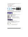
Working With Barcodes ...............................................................134
Working With Special Characters ................................................136
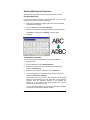
Working With Text Styles.............................................................137
Text Preferences .........................................................................138
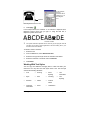
Working with Fonts ......................................................................140
12. Working with Paths ......................................................... 143
Creating Paths .............................................................................144
Selecting Points and Segments...................................................147
Using DesignCentral to Edit Points and Segments......................148
Path Direction ..............................................................................150
Editing Paths ...............................................................................150
13. Working with Bitmaps..................................................... 163
Using DesignCentral....................................................................164
Creating Bitmaps .........................................................................164
Changing Bitmap Properties........................................................166
Using the Bitmap Toolbar ............................................................169
Defining Marquees.......................................................................170
Editing Bitmaps............................................................................172
Using Filters.................................................................................179
Tracing Bitmaps...........................................................................182
14. Working with Effects....................................................... 189
Common Features .......................................................................189
Using Combine Effects ................................................................189
Using the Outline Effect ...............................................................193
Using the Shadow Effect .............................................................195
Using the Stripes Effect ...............................................................196
Using The Distort Effect...............................................................200
Using the Blending Effect ............................................................202
Using the Lens Effect...................................................................202
Using the Underbase Effect.........................................................204
Using the Finisher Effect..............................................................206
Using Color Trapping...................................................................207
Using Styles.................................................................................208
Using Contour Cut .......................................................................209
Contents
Page iii
15. Working with Measurements and Labels...................... 213
Measuring Distances ...................................................................213
Creating Dimensioning Lines.......................................................214
Automatically Dimensioning Objects............................................215
Dimensioning to Page..................................................................215
Creating Labels ...........................................................................216
Editing Dimension Lines ..............................................................217
16. Configuring the System for Color Printing................... 219
Setting the Input Profiles..............................................................219
Setting the Display Profiles..........................................................220
Selecting Rendering Intents.........................................................220
17. Printing to a Desktop Printer.......................................... 223
Previewing the Design .................................................................223
Print Options ................................................................................226
18. Cutting your Design ........................................................ 229
Setting the Cut/Plot Dialog...........................................................229
Cut / Plot Dialog - General Tab....................................................230
Cut / Plot Dialog - Panel Tab .......................................................234
Cut / Plot Dialog - Advanced Tab ................................................239
19. Printing your Design ....................................................... 243
Setting the RIP and Print Dialog ..................................................243
RIP and Print Dialog - General Tab .............................................244
RIP and Print Dialog - Panel Tab.................................................248
RIP and Print Dialog - Advanced Tab ..........................................252
RIP and Print Dialog – Driver Tab ...............................................256
RIP and Print Dialog - Color Tab .................................................256
Printing with Spot Colors .............................................................256
Contour Cutting ...........................................................................257
20. Setting up Production Manager ..................................... 263
Understanding Setups .................................................................263
Creating Your First Setup ............................................................263
Adding New Setups .....................................................................263
Configuring a Setup .....................................................................263
Setting up Production Manager on a Network .............................264
21. Using Production Manager............................................. 267
The Production Manager Window ...............................................267
Changing Preferences .................................................................268
Working with Setups ....................................................................269
Working with Jobs........................................................................276
Nesting Jobs ................................................................................279
Tiling and Cropping Jobs .............................................................282
Using the Color Profiler................................................................288
Using Custom Color Mapping......................................................288
Using Global Color Mapping........................................................290
Importing and Exporting Color Profiles ........................................292
Using Output Size Compensation................................................293
Page iv
Contents
Using RIP Logs............................................................................294
22. Setting Job Properties in Production Manager............ 297
Accessing the Job Properties Dialog ...........................................297
Setting the Preview Pane View....................................................298
Working with Job Property Presets..............................................298
Setting Default Job Properties .....................................................301
Setting Job Properties .................................................................301
Adding New Media Types to a Device .........................................317
Setting Ink Split Options ..............................................................318
Setting Advanced Color Correction Properties ............................320
Setting Dither Options for Angled Screens ..................................321
Setting Cutter Driver Options.......................................................323
Editing ICC Profile Properties ......................................................324
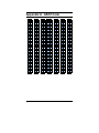
Appendix A - ASCII Code ...................................................... 329
Appendix B - Installation....................................................... 331
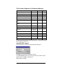
Appendix C - Supported File Formats ................................. 333
File Formats Supported in Design Application.............................333
File Formats Supported in Production Manager ..........................335
AutoCAD DXF Import ..................................................................335
Gerber File Format Supported Features......................................336
Appendix D - Features List ................................................... 337
Appendix E - CASmate Tracing Features............................ 339
Using Bezier Tracing ...................................................................339
Using Enhanced Curves Tracing .................................................339
Using Enhanced Corners Tracing................................................339
Using Centerline Vectorization ....................................................340
Using Color Vectorization ............................................................341
Appendix F – Keyboard Shortcuts....................................... 345
Index........................................................................................ 347
Contents
Page v
Page vi
License AgreementInstalling the Software
Software License Agreement
Carefully read the following terms and conditions sign and return as accepting
these terms and conditions.
This is a legal agreement between you, the end user (either an individual or an
entity), and Scanvec Amiable, Inc. If you do not agree with the following, you
should promptly return the package. Use of this program indicates your
acceptance of the terms and conditions stated below.
The enclosed computer program "Software" is licensed, not sold, to you by
Scanvec Amiable, Inc., for use on a non-exclusive, non-transferable basis, only
under the following terms, and Scanvec Amiable, Inc., reserves any rights not
expressly granted to you. You may not disclose to any third party any
confidential information concerning the Software or Scanvec Amiable, Inc. or use
such confidential information to the detriment of Scanvec Amiable, Inc...
1. License.
This software is protected by the United States Copyright Law and International
Treaty Provisions. Therefore, you must treat the Software just as you would any
other copyrighted material, such as a book. This license allows you to:
(a) Make one copy of the Software in machine readable form; provided
that such a copy of the original may be used solely for backup purposes.
As an express condition of this License, you must reproduce on each copy
of the Scanvec Amiable, Inc., copyright notice and any other proprietary
legends on the original copy supplied by Scanvec Amiable, Inc.
(b) Transfer the Software and all rights under this License to another party
together with a copy of this License and all written materials
accompanying the Software provided you give Scanvec Amiable, Inc.,
written notice of the transfer and the other party reads and agrees to
accept the terms and conditions of this License.
(c) Use this Software on a single computer only, but may transfer it to
another computer as long as it is used on only one computer at a time. “In
Use” constitutes being loaded onto either temporary (i.e., RAM) or
permanent memory (e.g., hard disk, CD-ROM or other storage device) of a
computer.
2. Restrictions.
You may NOT distribute copies of the Software to others or electronically transfer
the Software from one computer to another over a network. You may not decompile, reverse engineer, disassemble or otherwise reduce the Software to a
human perceivable form. You may not modify, adapt, transfer, rent, lease, loan,
resell for profit, distribute, network or create derivative works based upon the
software or any part thereof.
3. Termination.
This License is effective until terminated. This License will terminate immediately
if you fail to comply with any of its provisions. Upon termination, you must return
the Software, and all copies thereof, to Scanvec Amiable, Inc., and you may
terminate this License at any time by doing so.
4. Export Law Assurances.
You agree that neither the Software nor any direct product thereof will be
transferred or exported, directly or indirectly, into any country prohibited by the
Licence Agreement
Page vii
United States Export Administration Act or any international export laws and the
restrictions and regulations thereunder, nor will it be used for any purposes
prohibited by the Act or laws.
5. Warranty Disclaimer, Limitation of Remedies and Damages.
In no event will Scanvec Amiable, Inc., be liable for any damages, including
infringement, lost data, lost profits, cost of cover or other special, incidental,
consequential or indirect damages arising from the use of the program however
caused and on any theory of liability. This limitation will apply even if Scanvec
Amiable, Inc., or an authorized dealer or distributor has been advised of the
possibility of such damage.
SCANVEC AMIABLE, Inc. MAKES NO
WARRANTY, EXPRESS OR IMPLIED, WITH RESPECT TO THE SOFTWARE,
AND DISCLAIMS, WITHOUT LIMITATION, ANY IMPLIED WARRANTY OF
MERCHANTIBILITY OR FITNESS FOR A PARTICULAR PURPOSE. Scanvec
Amiable, Inc., does not warrant any drivers for plotting, scanning or either
devices. These drivers are provided for our customers as a service only, and
were developed using information provided to us at the time by the equipment
manufacturers.
Scanvec Amiable, Inc., is not responsible for any typographical errors in the
software or in the documentation.
6. General.
If you are a U.S. Government end-user, this License of the Software conveys
only "RESTRICTED RIGHTS," and its use, disclosure, and duplication are
subject to Federal Acquisition Regulations, 52.227-7013(c)(1)(ii). This License
will be construed under the laws of the State of Pennsylvania, except for that
body of law dealing with conflicts of law, if obtained in the U.S., or the laws of
jurisdiction where obtained, if obtained outside the U.S. If any provision of this
License is held by a court of competent jurisdiction to be contrary to law, that
provision of this License will remain in full force and effect.
© Copyright 2002 by Scanvec Amiable, Inc. All rights reserved. No part of this
publication may be reproduced, stored in a retrieval system or transmitted, in any
form or by any means, electronic, mechanical, photocopy, recording or
otherwise, without the prior written permission of the publisher. Printed in the
United States of America. The information in this manual is subject to change
without notice and does not represent a commitment on the part of Scanvec
Amiable, Inc.
Acrobat® Reader Copyright© 1987-2002 Adobe Systems Incorporated. All rights
reserved. Adobe and Acrobat are trademarks of Adobe Systems Incorporated
which may be registered in certain jurisdictions. PostScript®
software
Copyright© 1984-1998 Adobe Systems Incorporated. All rights reserved.
Flexi, FlexiFAMILY, FlexiSIGN-Pro, FlexiSIGN Plus, FlexiEXPERT, FlexiSIGN,
FlexiLETTER, FlexiDESIGNER, FlexiCUT, FlexiENGRAVE, PhotoPRINT Server,
PhotoPRINT, PhotoPRINT SE, EnRoute-Pro, EnRoute Plus, EnRoute, EnRouteMachine Shop, and/or other Scanvec Amiable products referenced herein are
either trademarks or registered trademarks of Scanvec Amiable, Inc. Illustrator is
a registered trademark of Adobe Systems Incorporated. FreeHand is a registered
trademark of Aldus Corporation. CorelDRAW! is a trademark of Corel Systems
Corporation. AppleTalk, ImageWriter, LaserWriter, and Macintosh are registered
trademarks of Apple Computer, Inc. Windows is a registered trademark of
Microsoft Corporation. The names of actual companies and products mentioned
herein may be the trademarks and/or registered trademarks of their respective
owners. Adobe® is a trademark of Adobe Systems Incorporated or its
Page viii
License AgreementInstalling the Software
subsidiaries and may be registered in certain jurisdictions. PostScript® is a
trademark of Adobe Systems Incorporated or its subsidiaries and may be
registered in certain jurisdictions.
Scanvec Amiable, Inc.
International Plaza Two, Suite 625
Philadelphia, PA 19113-1518
License Agreement for Users of Adobe® Configurable PostScript® Interpreter
and Coded Font Programs
1. Licensor grants to Licensee a nonexclusive sublicense, subject to Paragraph 7
below and the other provisions hereof (a) to use the CPSI Application Object
("Software") solely for Licensee's own internal business purposes in a single
central processing unit ("CPU"), optional associated display with a resolution of
less than one hundred fifty dots per inch, and, optionally, connected to a single or
multiple output device (the "Computer System"); (b) to use the digitally-encoded
machine-readable outline programs ("Font Programs") provided by Licensor in a
special encrypted format ("Coded Font Programs") and identified herewith to
reproduce and display designs, styles, weights, and versions of letters, numerals,
characters and symbols ("Typefaces") solely for Licensee's own customary
business or personal purposes on the Computer System; and (c) to use the
trademarks used by Licensor to identify the Coded Font Programs and
Typefaces reproduced therefrom ("Trademarks"). Licensee may assign its rights
under this Agreement to a licensee of all of Licensee's right, title and interest to
such Software and Coded Font Programs provided the licensee agrees to be
bound by all of the terms and conditions of this Agreement.
2. Licensee acknowledges that the Software, Coded Font Programs, Typefaces
and Trademarks are proprietary to Licensor and its suppliers. Licensee agrees to
hold the Software and Coded Font Programs in confidence, disclosing the
Software and Coded Font Programs only to authorized employees having a need
to use the Software and Coded Font Programs as permitted by this Agreement
and to take all reasonable precautions to prevent disclosure to other parties.
3. Licensee will not make or have made, or permit to be made, any copies of the
Software or Coded Font Programs or portions thereof, except as necessary for
its use with a single Computer System hereunder. Licensee agrees that any such
copies shall contain the same proprietary notices which appear on or in the
Software or the Coded Font Programs.
4. Except as stated above, this Agreement does not grant Licensee any rights to
patents, copyrights, trade secrets, trade names, trademarks (whether registered
or unregistered), or any other rights, franchises, or licenses in respect of the
Software, Coded Font Programs, Typefaces, or Trademarks. Licensee will not
adapt or use any trademark or trade name which is likely to be similar to or
confusing with that of Licensor or any of its suppliers or take any other action
which impairs or reduces the trademark rights of Licensor or its suppliers. The
Trademarks can only be used to identify printed output produced by the Coded
Font Programs. At the reasonable request of Licensor, Licensee must supply
samples of any Typeface identified by a Trademark.
5. Licensee agrees that it will not attempt to alter, disassemble, decrypt or
reverse engineer the Software or Coded Font Programs.
6. Licensee acknowledges that the laws and regulations of the United States
Licence Agreement
Page ix
restrict the export and re-export of commodities and technical data of United
States origin, including the Software or Coded Font Programs. Licensee agrees
that it will not export or re-export the Software or Coded Font Programs in any
form without the appropriate United States and foreign government licenses.
Licensee agrees that its obligations pursuant to this section shall survive and
continue after any termination or expiration of rights under this Agreement.
7. The Software licensed hereunder may be used to generate screen displays on
a single Computer System having a screen resolution of less than 150 dots per
inch and to generate output on the associated output device. Licensee agrees
not to make use of the Software, directly or indirectly, (i) to generate bitmap
images on a screen display with a resolution of 150 dots per inch or greater, (ii)
to generate Typefaces for use other than with the Computer System, or (iii) to
generate printed output on other than an output device that Licensor has
designated to be approved for use with the Software on the Computer System.
Any failure of Licensee to comply with this provision is a material breach of this
End User Agreement.
8. NEITHER LICENSOR NOR ANY OF ITS REPRESENTATIVES MAKES OR
PASSES ON TO LICENSEE OR OTHER THIRD PARTY ANY WARRANTY OR
REPRESENTATION ON BEHALF OF LICENSOR'S THIRD PARTY
SUPPLIERS.
9. Licensee is hereby notified that Adobe Systems Incorporated, a California
corporation located at 345 Park Avenue, San Jose, CA 95110-2704 ("Adobe") is
a third-party beneficiary to this Agreement to the extent that this Agreement
contains provisions which relate to Licensee's use of the Software, the Coded
Font Programs, the Typefaces and the Trademarks licensed hereby. Such
provisions are made expressly for the benefit of Adobe and are enforceable by
Adobe in addition to Licensor.
10. The Adobe Postscript Interpreter includes an implementation of LZW licensed
under U.S. Patent 4,558,302. The Adobe® PostScript© Interpreter, also referred
to as CPSI, is provided on an as is basis. Scanvec Amiable, Inc. is not
responsible for any damages arising from the use of the program however
caused and on any theory of liability.
Page x
License AgreementInstalling the Software
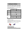
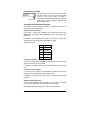
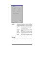
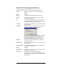
1. Installing the Software
Before you begin installing the software, read the hardware
requirements below. For optimal performance we suggest that your
system meet the recommended requirements. As with all computer
software, systems with faster processors, more RAM, and greater
amounts of storage space allow you to work with larger files and keep
your processing time to a minimum.
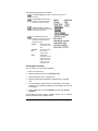
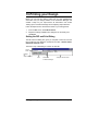
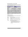
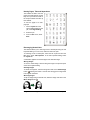
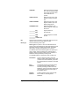
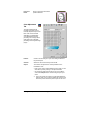
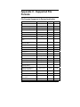
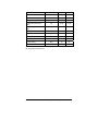
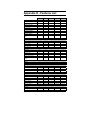
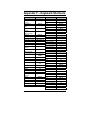
Recommended System Requirements
Processor
Windows
Macintosh
Pentium II 350 MHz
G3 300 MHz
RAM
256 Mbytes
Install Space
200 Mbytes
Working Disk
Space
4 Gbytes
Operating
System
Windows 98 / ME /
Windows NT4.0 / 2000 / XP
Video
OSX 10.2 or later
800x600 resolution monitor with 16 bit color
4x CD-ROM or DVD Drive
Other
Free USB or LPT Port for
hardware key
Free USB Port for
hardware key
Available Port for Output Device
Windows NT 4.0 requires Internet Explorer 5.x or greater & Service Pack 4
or higher.
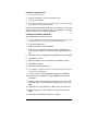
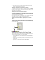
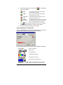
Installation Procedures
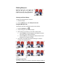
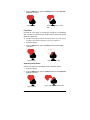
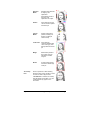
The software will not run without a hardware protection key, also known
as a dongle. The hardware key protects the software from being
unlawfully copied and must be connected to your computer whenever
you use the software.
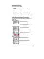
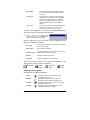
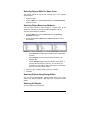
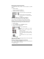
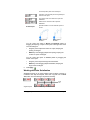
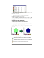
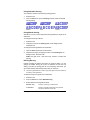
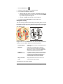
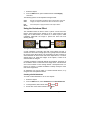
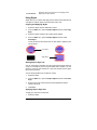
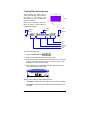
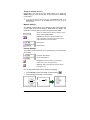
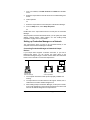
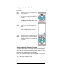
There are two types of hardware keys: Parallel and USB keys.1
USB key
Parallel key (Windows only)
1
The older Macintosh ADB key is no longer supported.
Installing the Software
Page 1
Installing a Hardware Key
1.
Turn off your computer.
2.
Plug the hardware key into the port (USB or LPT).
3.
Turn on your computer.
When using parallel port keys, we recommend that you plug your output
device and key into separate parallel ports.
Once the USB hardware key driver has been installed, the driver will
cause an LED built into the key to light. The USB driver is installed
automatically as part of the software installation.
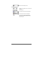
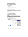
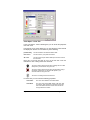
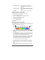
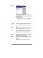
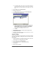
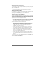
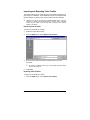
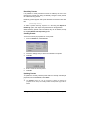
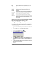
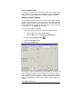
Installing the Software (Windows)
Follow these steps to install the software:
If you’re installing on a PC running Windows NT/2000/XP, you must have
Administrator privileges. See your Windows user guide for details.
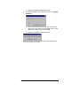
1.
Insert the Installation CD.
2.
Select a language and then click Next.
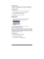
3.
Enter your user number and password and then click Next. The
User number and password can be found on the product hardware
key.
4.
Select the product and language to be installed and then click Next.
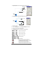
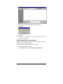
5.
Click Next to continue.
6.
Read the Software License Agreement and click Yes to accept.
7.
Click Next to continue.
8.
Click Yes to view the readme file.
The readme file contains last-minute issues and information that are not
included in this documentation.
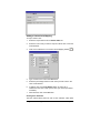
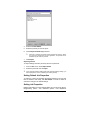
9.
You may change the default destination folder here. Click Next.
10. Select the type of installation to install. Typical is recommended.
Click Next.
11. Select the folder where the software will be included. If you accept
the default folder, a new folder will be created for the product. Click
Next.
12. Click Yes to clear the preferences or No to retain old preferences.
13. Select the printers you want to install color profiles for then click
Next.
14. Select Yes and click OK to restart your computer.
Page 2
Installing the Software
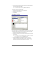
Uninstalling the Software (Windows)
1.
Exit your software by selecting Exit from File menu.
2.
In the Windows Control Panel, double-click the Add/Remove
Programs icon.
3.
Select your software from the list and click the Change/Remove
button.
4.
Click OK when finished.
5.
Go into the drive containing the directory where the software was
installed. Delete this folder.
Installing the Software (Macintosh)
Follow these steps to install the software:
1.
Insert the Installation CD.
2.
Double click the Installer icon.
3.
Select a language and then click OK.
4.
Enter your User ID and Password and then click OK.
The user ID and password can be found on the hardware key.
5.
Select the product and language to be installed and then click OK.
6.
Read the Software License Agreement and click Accept.
7.
Check that your hardware and operating system meet the RIP
Requirements and click Next.
8.
Select the Install Location and click Install.
9.
Click Continue to close down all other apps.
10. The software installs. Click Stop to halt installation.
11. Click Yes to clear the preferences or No to retain old preferences.
12. Enter your passphrase for the Rainbow Key installer and click OK.
13. Enter your passphrase for the Hasp Key installer and click OK.
14. Click Continue.
15. Click Quit.
16. Click OK.
17. Click Restart.
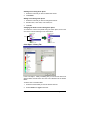
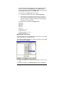
Follow these steps to install ICC color profiles for your printers:
1.
Insert the ICC Profile CD.
2.
Double-click on the installer for your language.
Installing the Software
Page 3
3.
Select the folder the software was installed into and click Choose.
4.
Select the printers you want to install color profiles for then click
OK.
Uninstalling the Software (Macintosh)
1.
Exit your software by selecting Quit from File menu.
2.
Drag the alias for your software from the desktop to the Trash.
3.
Drag the folder where your software was installed to the Trash.
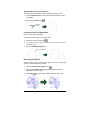
Using a Hardware Key Over a Local Area Network
It is possible to run the software on a different computer than the one
the hardware key is installed on. However, you cannot run more than
one concurrent instance of the software using the same hardware key.
To run the software using a hardware key installed on a different
computer:
1.
On the computer with the hardware key, make sure the software is
not running.
2.
Run Production Manager on the computer with the hardware key.
3.
On the computer you want to run the software on, make sure the
software is installed using the user number assigned to the
hardware key.
When you run the software on the second computer, it will recognize the
hardware key from the first computer and run.
Page 4
Installing the Software
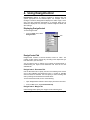
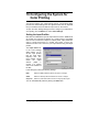
Using Preference Manager
Preference Manager is a utility that allows you to save all of the settings
in the software to a file, including all output device setups, setup
properties, default job properties, and all application preferences.
You cannot load a set of preferences while either the design software or
Production Manager is running. You can save preferences at any time.
Saving a Set of Preferences
To save the current set of preferences to a file:
1.
Run Preference Manager.
2.
Click Save.
3.
Type the name for the set of preferences in the field and click OK.
Loading a Set of Preferences
To reload a previously saved set of preferences:
1.
Exit the software.
2.
Run Preference Manager.
3.
Select the set of preferences you want to load.
4.
Click Load.
Restoring the Software to its Original State.
The default settings for the software are stored in the Default set of
preferences. Restoring the software to its default state may be
particularly helpful when troubleshooting any problems you may
encounter with your software.
Loading this set of preferences will remove all of the output device setups in
Production Manager.
Installing the Software
Page 5
To clear the preferences stored in your system:
1.
Exit the software.
2.
Run Preference Manager.
3.
Select Default.
4.
Click Load.
Exiting Preference Manager
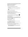
To exit Preference Manager, click Exit.
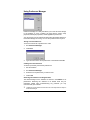
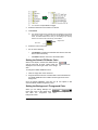
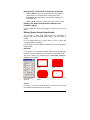
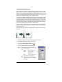
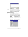
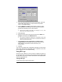
Password Installer
The Password installer is a utility that helps you manage the different
passwords that come with the software. After you have installed the
basic program with your main password, you should then launch the
Password Installer to add any additional passwords you may have.
Application Password - This is your main application password for
software.
Option passwords- If you have purchased additional options, you may
enter the option passwords to this field to upgrade your software.
Note: Make sure that the software is not running when you add a new
password.
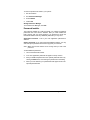
To add additional passwords:
1.
Launch the Password Installer.
2.
Your main application password will appear in the top section.
3.
Add your additional passwords to the optional password section by
clicking the Add button, and entering the password into the dialog.
4.
When you have finished, your password should appear in list in the
optional password field.
Page 6
Installing the Software
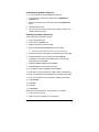
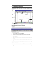
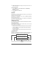
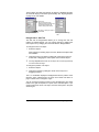
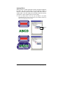
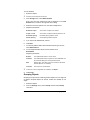
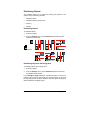
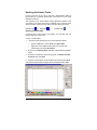
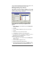
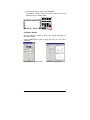
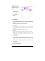
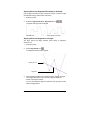
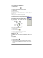
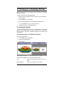
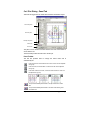
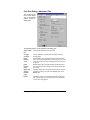
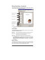
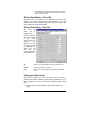
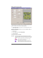
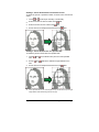
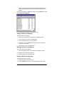
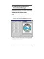
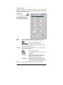
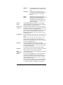
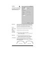
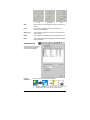
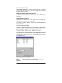
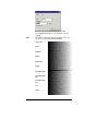
2. Getting Started
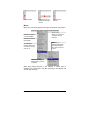
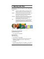
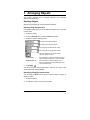
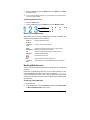
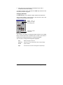
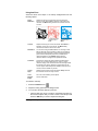
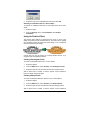
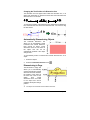
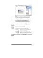
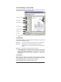
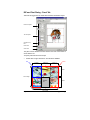
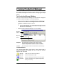
The illustration below shows some of the basic elements of your
software:
Main
Menu
Rulers
Main
Toolbar
Standard
Toolbar
Borders
Design Area
View
Toolbar
Scroll Bars
Swatch Table
Status
Bar
Cursor Position
Default Colors
Basic Elements of your Software
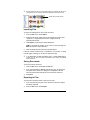
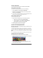
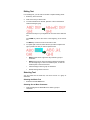
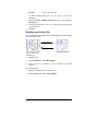
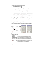
Toolbars
Toolbars are a set of commands grouped according to their function.
Standard toolbar
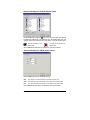
To show or hide a toolbar:
1.
From the View menu, select Toolbars.
2.
Check or uncheck the toolbars that you want to show or hide.
Or, in Windows:
3.
Right click the area around the design area where the toolbars are
docked.
4.
In the menu, select or unselect the toolbar that you want to show or
hide.
You can also hide a toolbar by clicking the Close button on the upper
right side of the toolbar.
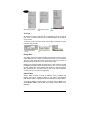
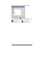
In Windows, toolbars are docked or floating. Docked toolbars are placed
Getting Started
Page 7
at fixed positions around the design area. Floating toolbars can be
placed anywhere in the design area. You can undock a toolbar, making
it a floating toolbar and then place it at any location in the design area.
Macintosh toolbars are always floating.
To undock a toolbar:
•
Drag the toolbar from its docked position. (Do not drag buttons).
Or
•
Double click the toolbar. (Do not double click buttons).
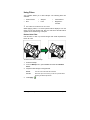
Dragging or double clicking the buttons will not undock or dock the toolbar.
Double click or drag to
undock the toolbar
Docked Toolbars
Undocked View Toolbar
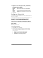
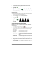
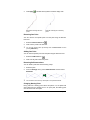
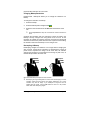
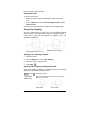
The shape of a floating toolbar can be adjusted by dragging its borders.
Standard toolbar in different shapes
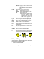
The shape of a floating toolbar can be adjusted by dragging its borders.
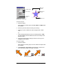
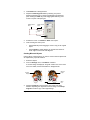
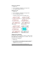
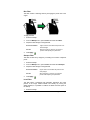
When a button has a small triangle on upper right corner, is
an indication that this button is a part of a tear-off palette.
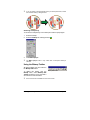
To use the tools in a tear-off palette:
1.
Click once on the button and drag it slightly to display the full
palette.
2.
Once it is displayed, you can either select the desired tool and
release the mouse button, displaying the new tool, or you can drag
the entire palette away from the original palette and release the
mouse to drop it on the drawing area.
Page 8
Getting Started
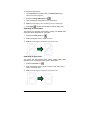
Original palette
Dragging the tear-off
palette and selecting a
new tool
The new tool is
selected
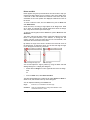
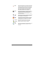
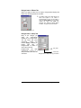
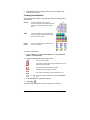
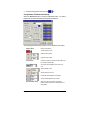
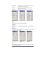
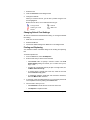
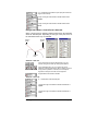
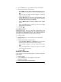
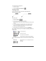
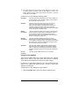
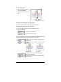
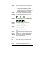
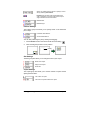
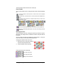
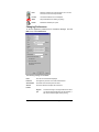
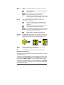
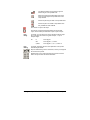
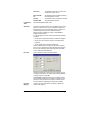
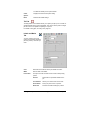
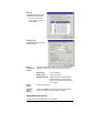
Menus
Menus are commands grouped by the types of operations they perform.
Enabled Command
Currently available.
Disabled Command
Not available.
On / Off button
Indicates whether the
command is currently
active or not.
Shortcut key
Allows you to select the
command using the
keyboard.
Ellipses (…)
Indicates that a dialog
box will be displayed
when this command is
chosen.
Submenu Indicator
Indicates that a submenu
is available.
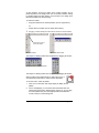
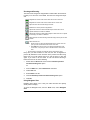
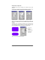
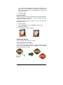
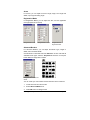
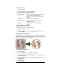
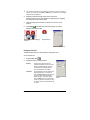
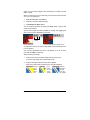
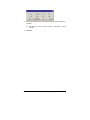
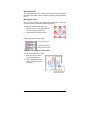
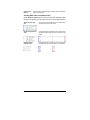
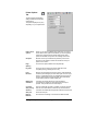
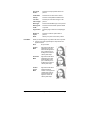
When right clicking elements in your software, a context menu is
displayed. The context menu will differ according to the element that
you are right clicking on.
Getting Started
Page 9
Right clicking a shape
Right clicking a blank
area
Right clicking the swatch
table
Tool Tips
All fields and control points that can be dragged will show tool tips to
help. Some commands will also show a brief description at the bottom
of your screen.
To show a tool tip, hover the cursor over the field, command or control
point for a few seconds.
Numeric field with a
tool tip
Control Point with tool
tip
Button with a tool tip
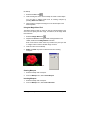
Design Area
The design area is the white area inside the software’s screen. It has a
border that serves as a guide and represents the size of your substrate.
The size of the design area does not limit the size of your design or
where the design is placed on your media during output.
Margins can be placed inside the design area. Those margins are used
to distribute and align objects inside the design area. You can change
the size and the color of the drawing area and show or hide the borders.
See “DesignCentral - Document Tab” on page 43 for more information
on how to set up your document properties.
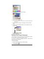
Swatch Table
Swatch tables includes a group of standard colors, gradients and
patterns that can be applied to objects in your design. See “Working
With Swatch Tables” on page 80 for more information on swatch tables.
To toggle the display of swatch tables on and off, from the View menu,
select Swatch Table. This will also force hidden swatch tables to be
displayed.
Page 10
Getting Started
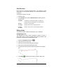
Rulers and Grid
Rulers appear along the top and left side of the main screen to help you
measure and align objects. As you move the cursor in the design area,
a tick mark on each ruler follows the movement of the cursor. Also, the
coordinates of the cursor position are displayed at bottom left corner of
the screen.
To show or hide the rulers, from the View menu, point to Show and
click Show Rulers.
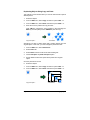
Grids, like rulers, can help you align objects in the design area. Grids
are a series of horizontal and vertical dotted lines within the design
area. They will not show as part of the output.
To show or hide the grids, from the View menu, point to Show and click
Show Grid.
The rulers, grids and all other numeric values that represent a length
follow a unit system defined in your software. To change the unit
system, right click a ruler and select the new unit. On Macintosh, click
and hold on the mouse button on the rulers.
By default, the origin of the rulers is located in the lower left corner of
the design area. To change the origin, you can click and drag the origin
icon in the upper left corner of your screen.
Click and drag the Origin icon
The new Origin
You can also adjust the origin’s position by using the Ruler and Grid
Settings dialog box. To display this dialog box:
•
Double click the Origin icon in the upper left hand corner of design
area
Or
•
From the View menu, select Ruler and Grid.
The Ruler & Grid dialog box consists of two Tabs, Rulers and Grid. To
select a Tab, click the tabs on the top of the dialog box.
You can adjust the following on the Ruler Tab:
Origin
Enter the X, Y coordinates of the new origin.
Orientation
Click one of these buttons to change the orientation of the
coordinates in the X, Y rulers.
Getting Started
Page 11
Units
Select the unit system that will be used for length values from this
list.
You can adjust the following on the Grid tab:
Spacing
Horizontal and vertical space between adjacent dots.
Snap to
grid
Check this option to snap the objects to the grid while moving or
resizing an object.
Guides
Guides allow you to visually align design elements on your document.
To show or hide the guides, from the View menu, point to Show and
then click Show Guides.
You can create a guide line by:
•
Clicking and dragging one point on the ruler. Horizontal or vertical
guide lines are created, depending on which ruler you dragged the
point from.
Click and drag
Click and drag a point in the ruler
•
A new vertical guide is created
Select objects and from the Arrange menu, point to Guides and
click Make Guide. Select Release Guide in the same menu to
convert guides back to original objects.
To create a diagonal guide, create a horizontal or vertical guide, unlock the
guides and then rotate the horizontal or vertical guides in DesignCentral Rotate Tab
Select the objects
•
Objects converted to guides
In DesignEditor, drag objects from generic layer to Guide Layer.
For more information about the Guide Layer see “DesignEditor Layers Tab” on page 49.
To lock the guides:
•
From the Arrange menu, point to Guides and click Lock Guides.
Page 12
Getting Started
Guides cannot be selected by dragging a bounding box around them. You
have to click the guide.
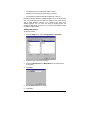
To select all guide lines:
1.
From the Edit menu, point to Select and then click Select by
Attributes command.
2.
Select Guide Line in Object Tab.
3.
Click OK.
Status Bar
The Status bar is the area located on the bottom of your screen and
displays the following information:
The present X, Y coordinates of the cursor or additional information
about the selected command.
The default fill and stroke colors or the foreground and background
colors (when in bitmap editing mode).
Changing the View
You have several commands to change how the design area is viewed.
Using a Wheel Mouse
If your computer is equipped with a wheel mouse, you can use the
mouse wheel to control the view:
•
Moving the mouse wheel up and down pans the view up and down.
•
Holding the SHIFT key and moving the wheel up and down pans
the view left and right.
•
Holding the CTRL key and moving the wheel up and down zooms
the view in and out.
Using Scroll bars
Scroll bars are horizontal and vertical bars located in the bottom and
right side of your design area. Use them to scroll the design area.
Click the arrows on both sides to scroll
the design area in small increments
Click the blank area to move the
design area in large increments
Click and drag to scroll the design area
Getting Started
Page 13
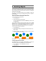
Zooming and Panning
The Zoom tools changes the magnification of items within the document
to allow you to see more or less detail. This does not change the output
size.
Magnifies the center of the view to twice the size of current view.
Magnifies the center of the view to half the size of current view.
Adjust the view size to fit the design area size.
Switches the view to previous magnification.
Adjusts the view size to fit the selected objects. When there are no
objects selected, this button is disabled.
Adjusts the view size to fit all existing objects. When there are no objects
in the design, this button is disabled.
Select this tool and click and drag inside the design area to pan the view
position.
Select this tool and
Click to zoom in at twice the magnification of the current view. The
point you click on will become the center of the view.
Hold CTRL and click to zoom out to half the magnification of the
current view. The point you click on will become the center of the
view.
Click and drag to magnify one particular portion of the design area.
Every time you click the Zoom or Pan tool, the view is magnified or
panned. By default the cursor will return to the previous tool after using
these tools. You must reselect the tool to use the Zoom or Pan tool
again. If you want to use the Zoom or Pan tool without selecting it
before each use do one of the following:
•
Double click the Zoom tool and uncheck the Resume previous
tool after zooming once option.
Or
1.
From the Edit menu, select Preferences command.
2.
Click Tools Tab.
3.
Select Zoom in the list.
4.
Uncheck Resume previous tool after zooming once option.
5.
Click OK.
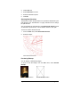
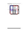
Using Navigator View
Navigator View allows you to view your entire document and specify
which portion to display.
To show the Navigator View, from the View menu, select Navigator
View.
Page 14
Getting Started
View Area
Navigator View
Design Area
To change the view:
•
Click and drag a point inside the View Area to pan the portion
displayed in the design area.
•
Click and drag a control point around the View Area to resize it,
causing a zoom in or zoom out in the design area.
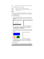
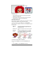
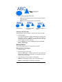
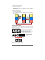
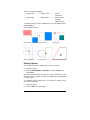
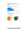
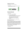
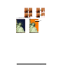
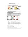
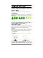
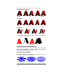
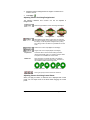
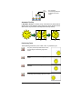
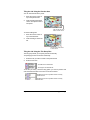
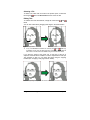
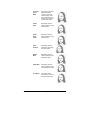
Showing an Object’s Fill
When the Show Fill option is enabled, every vector object is displayed
with its fill. When disabled, only the outline will be visible.
To show or hide the fill, from the View menu, select Show Fills.
When Show Fills is disabled, the outlines can be displayed using the
following modes:
Show layer
color
All outlines are displayed using the layer color. See
“Changing the Layer Color” on page 51 about how to
change the layer’s color
Show fill color
The outlines are displayed using the object’s original fill
color
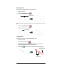
Show path
direction
The outlines are displayed using three colors. Green
for clockwise paths, Magenta for counter clockwise
paths and Gray for open paths. Selected objects will
still be displayed using the layer color.
Show Fills
Enabled
Show Fills
Disabled
(Show fill color)
Show Fills
Disabled (Show
layer color)
Show Fills
Disabled (Show
path direction)
To change the way the outlines are displayed:
Double click the Fill Mode tool and select the Wireframe option.
Or
1.
From the Edit menu, select Preferences command.
Getting Started
Page 15
2.
Click Tools Tab.
3.
Select Show Fills in the list.
4.
Select the Wireframe option.
5.
Click OK.
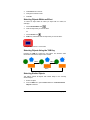
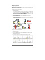
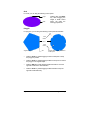
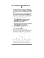
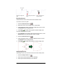
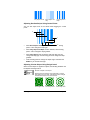
Showing Path Directions
The direction in which the path will be cut or plotted is determined by the
path direction. See “Path Direction” on page 150 about how to change
the path direction.
You can visualize the path direction using Show path direction mode
as described in previous item, or show direction arrows in each path.
To show or hide the direction arrows:
1.
From the View menu, select Show Path Direction.
2.
Select the object.
Paths with direction arrows
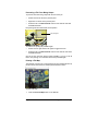
Previewing Bitmaps
You can display or hide bitmap images.
To show or hide the bitmap, from the View menu, select Preview
Bitmaps.
Preview Bitmaps Enabled
Page 16
Preview Bitmaps Disabled
Getting Started
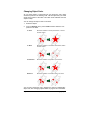
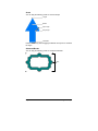
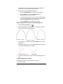
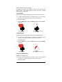
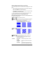
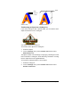
Showing Preview
When Show Preview is on, a copy of the object as it is being edited or
moved is displayed. When this option is off, a rectangle representing the
bounding of the object is displayed. Performing memory-intensive
operations in complex objects may slow the system performance when
Show Preview is on.
To show or hide the preview, from the View menu, select Show
Preview.
Previous Location
Moving an object with Show Preview
off
Moving an object with Show Preview
on
Redrawing the Design Area
Occasionally, when you edit your design, those changes are not
reflected accurately. To make sure that the design area is fully updated,
select Redraw command from the View menu. This forces a redrawing
of the design area.
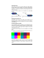
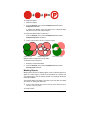
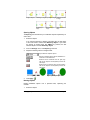
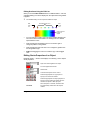
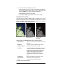
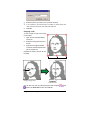
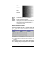
Previewing Objects in CMYK
If you are going to print your document, you can preview how your
output will look by using the CMYK soft preview. This feature will alter
the colors in your document to show how they will look when printed.
The colors outside the CMYK gamut will be adjusted to the nearest
possible CMYK color value.
To preview the colors in CMYK mode, from the View menu, select Soft
Proof.
If objects in your document and the swatch table appear “washed out”, it
may be because the Soft Proof feature is on.
Soft Proof is Off
Soft Proof is On
To accurately preview the colors, you have to set up the correct Color
Profiles and Rendering Intents that will be used in printing. See
“Configuring the System for Color Printing” on page 219 for more
details.
Getting Started
Page 17
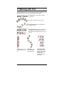
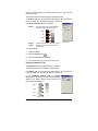
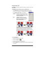
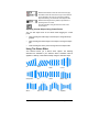
Filtering Objects by Color
Objects may be filtered by their color in the design area. For example,
you can show all objects using RGB color space, or all green objects.
To filter objects using the Color Filter:
1.
From the View menu, select View Filter.
2.
Select the colors that will be visible.
3.
•
Click the color space checkbox to select all colors from this
color space.
•
Click the specific color within one color space to select or
unselect this color.
•
Click Show All to select all colors from all color spaces.
•
Click Show None to unselect all colors from all color spaces.
Click OK.
Filtering settings will not be saved with your document. The next time you
open this file, all objects will be visible.
You can also filter objects by color using the context menu in the Color
Swatch table:
1.
Place the cursor over the color in the Swatch Table.
2.
Right-click the Swatch Table. A menu is displayed.
3.
From the View menu select the filtering option. The following
options are available:
Hide This Color
Objects using this color will not be visible.
Show This Color
Objects using this color will be visible.
Show All Except
This Color
Only the objects using this color will not be visible.
Hide All Except This
Color
Only the objects using this color will be visible.
Show all colors
All objects will be visible.
Cursor over the Swatch Table
Page 18
After selecting Hide This Color
Getting Started
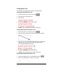
Tracking your Steps
Your software contains several tracking tools to retrace your steps,
making it easier to recover from operation mistakes.
Undoing and Redoing the Last Step
To undo the last operation, from the Edit menu, select Undo _____.
The name of the last operation is displayed after the Undo command.
To redo a step that you have just undone, from the Edit menu, select
Redo _____.
Undoing and Redoing Multiple Steps
Instead of undoing just the last operation, you can undo a sequence of
multiple steps.
1.
From the Edit menu, select Undo Multiple.
A list with all recent steps is displayed. The steps are shown in
order, with the most recent step appearing on the top of the list.
2.
Click to select the steps that you want to undo, starting from the
top.
The design area dynamically shows a preview of the undoing
process.
3.
Click OK to confirm and apply the undo.
The selected steps are undone and placed in a redo list.
The Redo list after
Undo
Selecting steps to Undo
The Undo list after
Undo
Getting Started
Page 19
After undoing multiple steps, if you decide that you didn't want to undo
those actions:
1.
From the Edit menu, select Redo Multiple.
A list with undo steps is displayed.
2.
Click and drag to select the steps that you want to cancel the undo,
starting from the top.
The design area dynamically shows a preview.
3.
Click OK.
The number of undo and redo operations that is allowed can be
adjusted. For example, if you set the number of steps to 50, after
th
st
st
performing the 50 step, the 1 step will be discarded and the 51 step
will be placed at the top of the list.
To adjust the number of steps stored in undo list :
1.
From the Edit menu, select Preferences.
2.
In General Tab, enter the number of steps in Maximum undo/redo
3.
Click OK.
Repeating the Last Step
To repeat the last step, select Repeat from the Edit menu. The name of
the last operation will be displayed after the Repeat command.
Only the following commands can be repeated:
• Moving objects
• Duplicating objects
• Scaling objects
• Applying effects
Using Workspaces
Workspace stores how and where the menus, buttons, commands and
keyboard shortcuts are defined. By changing the Workspace feature,
you can rearrange the software’s interface to look more like the design
software that you are more comfortable with.
To change the workspace, from the File menu, point to Workspace and
select the workspace.
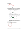
Entering Numerical Values
The software supports a number of unique features that make it easier
to enter numerical values.
Page 20
Getting Started
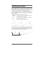
Using Spinner Controls
Spinner Control
Use the spinner controls to increase or decrease
the value. When you click, or click and hold, the
mouse on one of the arrows, the value is
increased or decreased incrementally. Using the
arrow keys on your computer’s keyboard will
have the same effect.
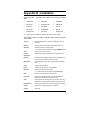
Using Built-In Arithmetical Operations
The software is able to perform a number of calculations whenever a
numerical value is being entered.
Automatic Unit Conversion
If you enter a value using a different unit of measurement than the
default unit, the software will automatically convert the value to the
default unit.
For instance, if your default unit is inches, you can enter a value of 1 ft,
and the software will convert the measurement to 12 in.
Supported units are:
in, "
inch
ft, '
foot
mm
millimeter
cm
centimeter
m
meter
pt
point
Calculation of Ratios
If you enter a ratio in the format A:B, the software will scale the previous
value in the field by the ratio entered.
For instance, if a value is set to 12, and you enter 2:3, the new value will
be 8.
Calculation of Percentages
If you enter a percentage in the format X%, the software will scale the
previous value in the field by the percentage entered.
For instance, if a value is set to 10, and you enter 90%, the new value
will be 9.
Simple Arithmetic Operators
If you enter a simple arithmetic expression, the software will calculate
the result of the expression and enter that value in the field.
The available arithmetic operators, in order of precedence, are:
Getting Started
Page 21
/
Division
*
Multiplication
+
Addition
-
Subtraction
For example, if you enter 1/8, the value 0.125 will be calculated.
Operator precedence determines the order in which the arithmetic
operations will be calculated when more than one operation is specified.
In the previous list, operators are listed from top to bottom in order of
operator precedence. For instance, if you enter 6/2*3, the software will
calculate 6/2 first then multiply the result by 3, yielding a result of 9.
Automatic Application of Entered Values and Arithmetic
Once you enter a numerical value, ratio, or arithmetic expression in a
numerical field, the software will automatically apply that value after a
brief delay. You can also press TAB to apply the value immediately.
Avoid pressing ENTER, as it will trigger the OK button and close the
dialog.
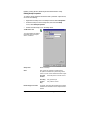
Setting Preferences
Many aspects of your software may be saved so that they are set up the
way you like every time you open a new file. These settings are known
as program preferences.
There are other settings that are saved on a document basis. Which
means that each time you open or save a document, the settings will be
applied only for that particular document. These settings are known as
document preferences.
To change the program preferences, from the Edit menu, select
Preferences.
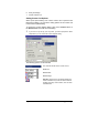
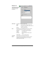
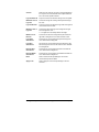
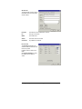
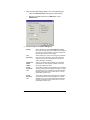
Preferences - General Tab
In this dialog box, you can set the general attributes of your software:
Maximum
Undo/Redo
Determines the number of operations stored in the undo
/ redo list. Smaller values in this field use less memory.
Selection
Tolerance
Determines how close the cursor must be from the
object to select it. Setting a larger value makes it easier
to select points.
Constrain
Angle
Sets the constrain angle when you rotate an object with
the SHIFT key pressed. The rotation will be performed
in increments defined by this field.
Save
Documents
Every
Open documents will be periodically saved. You can
specify the time period between saves.
Trash Capacity
Number of objects that can be saved in the trash layer.
Page 22
Getting Started
Precision
Number of decimals in numeric fields.
Restore
Defaults
Click this button to restore the default settings for above
fields.
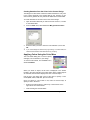
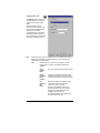
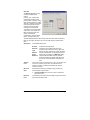
Preferences - File Path Tab
In this dialog box, you can set the default folders used in your software:
Document
The default folder used to store your documents.
Temporary
Files
The default folder used to create temporary files. If you
have multiple hard disks, select a folder in the hard disk
with more free space available.
Adobe Plugins
If you have the Adobe Photoshop installed, specify here
the folder where the plug-ins are stored.
Browse
Click this button to change the folder.
Restore
Defaults
Click this button to restore the default settings for above
fields.
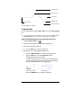
Preferences - Font Tab
In this dialog box, you can set the default settings for external FSfonts:
Path
The folder where the FSfonts are stored.
Add
If the FSfont is protected by a password, click this button
to enter the password.
Delete
Click this button to delete the selected password.
Browse
Click this button to change the folder.
Restore
Defaults
Click this button to restore the default settings for above
fields.
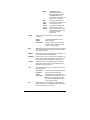
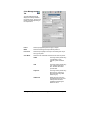
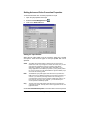
Preferences - Tools Tab
In this dialog box, you can set the default settings for some of the tools
available in the software.
Apply
Template
These preferences allow you to specify the default
template used when you apply a template. See “Using
Templates” on page 38.
Combine
Options
These preferences allow you to specify the options
used in Combine effect. See “Combine Effect Options”
on page 192.
Cut/Plot
This tool allows you to specify that the software must
communicate with Production Manager using TCP/IP.
or
RIP and
Print
Clear this box if the operating system is not
Windows NT, 2000 or XP, or if the computer is
running firewall software that might interfere with
TCP/IP communications.
This setting is not present on the Macintosh.
Getting Started
Page 23
Page 24
Meter
These preferences allow you to specify the colorimeter
used in your software to measure color values and the
port where the measurement device is connected. For
more information about how to use the measurement
device, see “Defining New Colors Using the Color
Specs Dialog” on page 87 and “Modifying Existing
Color Libraries (Windows Only)” on page 93.
Paste
These preferences allow you to specify if the copied
objects will be automatically created when pasted, and
the offset distance from the original object. See
“Duplicating Objects Using Copy and Paste” on page
64 for more information.
Select
Tool
These preferences allow you to specify how the objects
will be selected. See “Selecting Objects Using Select
Tool” on page 55 for more information.
Show
Fills
These preferences allow you to specify how the paths
are displayed when the Show Fill option is off. See
“Showing Object’s Fill” on page 15 for more details.
Text Tool
Sets several aspects of the text tool. See “Text
Preferences” on page 138 for more information.
Tip of the
Day
Displays a tip when you start your software.
Zoom
Selects if the zoom and pan tool will be used only once.
See “Zooming and Panning” on page 13 for more
information.
Getting Started
Macintosh User Interface Features
The following section lists features of the Macintosh user interface that
are different than the corresponding features under Windows.
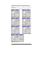
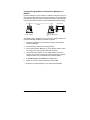
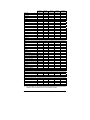
Macintosh Shortcut Keys
When keyboard shortcuts are listed, use the following list to find the
equivalent shortcut key on the Macintosh.
Windows System
Macintosh System
=
Click the mouse while holding down the
CONTROL key
CTRL key
=
COMMAND key (apple/clover)
Right-click the mouse
ENTER key
=
RETURN key
BACKSPACE key
=
DELETE key
DELETE key
=
DEL key
You can access the context menu for the ruler and swatch table by clicking
on them and holding the button down.
Macintosh Menus
The following menu items are in different places on the Macintosh than
they are under Windows.
Windows Menu > Item
Macintosh Menu > Item
File > Exit
=
[Application] > Quit
File > Print Setup
=
File > Page Setup
Recently viewed files (bottom of
File menu)
=
File > Open Recent
Edit > Preferences
=
[Application] > Preferences
Edit > Paste Special
=
[No Macintosh equivalent.]
Help > About
=
[Application} > About
Other Controls
The following controls are found in a number of dialogs, and are named
differently on the Mac.
Windows Control
Browse button
Macintosh Control
=
Choose button
Getting Help
From the Help menu, point to Help Topics to view the full online
documentation for the software. The online help contains all of the
information in this guide, plus information on all the other commands in
your software.
Getting Started
Page 25
Exiting the Software
To exit the software under Windows:
•
From the File menu select Exit.
•
Right-click on the software icon in the system tray and select Exit
from the context menu.
To exit the software under Macintosh OS X:
•
From the FlexiSIGN-PRO menu, select Quit FlexiSIGN-PRO.
•
Hold down the CONTROL key and click on the FlexiSIGN-PRO
icon in the dock. From the contextual menu, select Quit.
Page 26
Getting Started
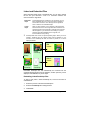
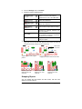
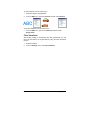
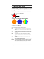
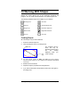
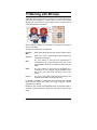
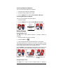
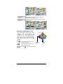
3. Working with Files
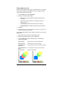
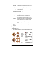
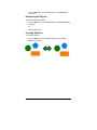
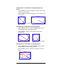
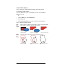
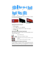
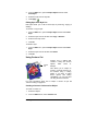
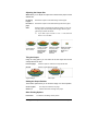
Your document can contain any combination of vector, bitmap, OLE or
PostScript objects.
Vectors
Vectors are a collection of straight or curved segments. These
objects can be scaled to any size without losing detail or clarity.
Shapes like rectangles, circles and text are vector objects.
Bitmaps
Also called raster images, bitmaps are formed by a grid of small
dots, known as pixels to represent images. Each pixel is
assigned a specific location and color value. A low resolution
bitmap image can appear jagged when printed.
PostScript
Images described using a page-description language known as
PostScript. These objects can contain a combination of vector
and bitmap images. When imported into your document,
PostScript objects can be parsed or previewed.
OLE
OLE is the abbreviation of Object Linking and Embedding and it
is available only for Windows. OLE is a compound document
standard developed by Microsoft and it enables you to create
objects with one application and then link or embed them in your
document.
Vector objects
Bitmap
object
Parsed PostScript
object
OLE object
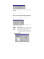
Creating New Documents
To create a new document:
•
From the File menu, select New.
Opening Files
To open an existing file:
1.
From the File menu, select Open.
2.
Select the file format, folder and the file that will be opened. See
“Appendix C - Supported File Formats” at page 333 for all
supported file formats.
3.
Click Open.
If the file contains fonts that are not installed in your system, a
dialog box will appear, allowing you to select a replacement font.
Working with Files
Page 27
Double clicking the file icon in Windows Explorer or dragging the file icon to
your software icon on desktop, will start the application and open the file.
Double click to open the file
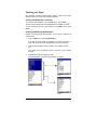
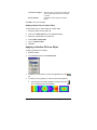
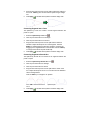
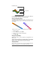
Importing Files
To import an existing file into the current document:
1.
From the File menu, select Import.
2.
Select the file format, folder and the file that will be imported. See
“Appendix C - Supported File Formats” at page 333 for all
supported file formats.
3.
Click Import. A bounding box will be displayed.
TAB key changes the position of the cursor on the bounding box.
ESC key stops the import operation.
4.
Click the design area and place the imported object.
If the file contains fonts that are not installed in your system, a dialog
box will appear, allowing you to select a replacement font.
If the Auto-place on paste and import option in Paste preferences is
enabled, the file will be imported immediately after clicking the Import
button in step (3).
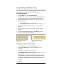
Saving Documents
To save the current document:
1.
From the File menu, select Save or Save as.
2.
If you have selected the Save as command or your are saving the
document for the first time, a dialog box is displayed. Enter the
name and the location that will be used to save the document.
3.
Click Save.
Exporting to Files
To export the current document or part of it into a file:
1.
If you are exporting only part of your document, select the objects
that will be exported.
2.
From the File menu, select Export.
Page 28
Working with Files
3.
Select the file format, folder and the file name. See “Appendix C Supported File Formats” at page 333 for all supported file formats.
The following options are available:
4.
Selection
only
Check this option to export only the selected objects.
Suppress
options
Some file formats will show an option dialog box before
exporting to a file. Check this option to bypass the options
dialog box.
Click Export.
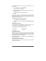
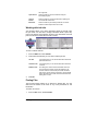
Emailing a Job (Windows Only)
To send the current job to someone as an email attachment, from the
File menu, select Send.
A new email message will be created in your default email program, and
the current job will be added to the message as an attachment.
Sending a Job to EnRoute (Windows Only)
If you have the EnRoute program installed on your computer, the
software allows you to transfer the current design directly to EnRoute.
To transfer the current design to EnRoute, from the File menu, select
Send to EnRoute.
Closing Documents
To close the current document:
1.
From the File menu, select Close.
2.
If your document have been changed since the time it was last
saved, a dialog box is displayed asking if you want to save the
current document.
•
Click Yes to save the document before closing it.
•
Click No to close the document without saving.
•
Click Cancel to exit the closing procedure.
Working with Files
Page 29
Linked and Embedded Files
When importing bitmap, EPS or PostScript files, you can link or embed
the file into your document. A link is a connection between the
document and the original file.
Embedded
object
An embedded object is contained in your document. Once a
file is embedded, there is no longer a connection between it
and the file from which it came. Changes to the original file
have no effect on the embedded object.
Linked
object
When an object is linked, only a reference to the image file is
stored in the document. The image information remains in the
original image file. If the image file is changed, those changes
will also appear in your document. Since linking to a picture
preserves the original attributes of the image file, it is
recommended for color printing.
PostScript files often contain an optional preview graphic. When you link or
embed a PostScript file, the preview graphic will be displayed in your
document. If the PostScript file does not contain a preview, a “X” will be
displayed instead.
Document
PostScript File
With
Preview
Embedded
Bitmap
Linked
PostScript
PostScript File
Without
Preview
Embedded
Postscript
Linked
PostScript
Embedded PostScript files will automatically be converted into the
equivalent drawing objects from the software, at which point they can be
displayed and edited like any other object.
Embedding Linked PostScript Files
To read in and parse a linked PostScript file, so that it becomes an
embedded file:
1.
Select the preview of the linked PostScript file.
2.
Select the PostScript tab in DesignCentral.
3.
Click Parse.
Page 30
Working with Files
Using OLE Objects (Windows Only)
The OLE (Object Linking and Embedding) feature of Windows allows
you to import objects that were created using other software installed on
your computer such as spreadsheet and word processors.
Inserting OLE Objects
1.
From the Edit menu, select Insert New Object.
2.
Select the type of object you want to create. Only programs that are
installed on your computer that support OLE appear in the list.
3.
Select Create New option to create a new OLE object using the
selected application.
Check Display As Icon to show the OLE object simply as an icon.
Click Change Icon button to change the icon.
4.
The selected programs will start, creating a window inside your
software.
5.
Resize and edit the contents of the window, using the selected
program.
6.
To finish using the selected program, press ESC key or click
anywhere outside the program window.
Design area with an Excel
spreadsheet.
After the OLE object has been
inserted
Inserting Existing Files as OLE Objects
1.
From the Edit menu, select Insert New Object.
2.
Select Create From File to merge an existing file into your
document.
3.
Click Browse and find the file to be inserted.
•
Check Display As Icon to show the OLE object simply as an icon.
Click Change Icon button to change the icon.
•
Check Link option to link the selected file. The object in the file will
be stored apart from the document, and all the changes made in
the source file will be reflected in your document. If the Link option
is unchecked, the object will be embedded and stored with the
document.
4.
Click OK.
Working with Files
Page 31
The document with a linked OLE object.
Editing OLE Objects
To edit an OLE object:
1.
Select the OLE object.
2.
From the Edit menu, point to [...] Object and then click Edit or
Open.
When you select Edit, the program associated with the OLE object will
start in a window inside your document and will be finished after the
edition. If you choose Open, a full instance of the program will start and
you may leave this application running even after editing the OLE
object.
Double clicking the OLE object has the same effect as Edit command
Converting OLE Objects
You can convert OLE objects to another format:
1.
Select the OLE object.
2.
From the Edit menu, point to […] Object and then click Convert.
3.
Select the new format from the list.
4.
Click OK.
You can also convert OLE objects to basic segments and bitmaps:
1.
Select the OLE object.
2.
From the Arrange menu, select Convert Linked to Native.
Changing Linking Properties of OLE Objects
1.
From the Edit menu, select Link.
2.
Change the following linking options:
Automatic /
Manual
By default, linked objects are set for Automatic updating.
This means that your software automatically updates the
linked information every time you open the document or
any time the linked file changes when the document is
open. Select Manual to update the object in your
document only when you choose to manually update it.
Update Now
When in Manual mode, click this button to updates the
OLE object in your document to reflect the situation of
Page 32
Working with Files
the original file.
Open Source
Click this button to open the linked file using the
associated program.
Change
Source
Click this button to change the linked file, replacing the
current file with another one.
Break link
Click this button to permanently break the connection
between a linked object and its source file.
Working with Job Info
Your program allows you to store information about the job with each
file you create. You can add or change information about a job at any
point in the design and production process. This information becomes
part of the file and is saved when the file is saved.
Job Tab
Customer Tab
Statistics Tab
To view or edit the Job Info:
1.
From the Edit menu click Job Info.
2.
There are three tabs that you can view or edit the job info:
3.
Job Tab
In this dialog box you can edit the information about this
particular document.
Customer Tab
In this dialog box you can edit the information about the
customer.
Statistics Tab
This dialog box contains stored information about the
job, including the amount of time spent editing it, the
number of times it was revised (the number of times it
was saved), as well as other information. Clicking Reset
button will restore the number of revisions and the total
editing time on a file.
Click OK.
Finding Files
The Find File feature allows you to search for specific files. You can
search the file based on file name or any of the parameters of Job
Information.
To search for one file:
1.
From the File menu, select Find File.
Working with Files
Page 33
2.
Click Browse and select the folder where the search will be
performed. If you want to search all sub folders check the Include
subfolders option.
3.
Enter the search condition:
•
If you want to search a file by its name, enter the file name in
Named field.
•
If you want to search a file using any of the job information,
select the job info field from the list provided and enter the
search text in the contains field. For example, to search for all
jobs where the order was taken by John Doe, you would select
Order Taken by and type John Doe into the contains field.
4.
Click Search button.
5.
A list with all files matching the search condition will be displayed.
6.
Select the file in list and:
•
Click Job Info button to show the job information.
•
Click Open button or double click the file in the list to open the
file.
•
Click Cancel button to end the search.
Job Estimation
Job Estimation is a tool for producing price estimates of your job. The
Job Estimation stores accounting information for each job, calculates
price automatically, and gives a price estimate. The information can
always be changed or customized to reflect your costs and needs.
This feature is intended to be a guideline and therefore all results should be
thoroughly reviewed before basing any business or financial agreements
upon them.
The estimation is calculated based on some elements of your design
like the number of characters or the material area. These values are
automatically gathered from your document. Other values like
preparation time must be manually entered when doing the job
estimation.
Those cost elements used in job estimation are grouped in Category,
Item and Type:
Page 34
Working with Files
Category
Item
Type
Color Printing
Color
CMYKLcLm printing
CMYKOrGr printing
Spot Color
Material Area
Color Correction
ICC Customization
File Preparation
PostScript File Creation
Economy
All Types
Fluorescent
All Types
Translucent
All Types
Using Job Estimation
1.
From the Edit menu click Job Estimation.
2.
Select the Form type.
3.
Select the Item in the list and edit the Unit Cost, Quantity and One
Time fields for selected item. Repeat this process for all items that
need any correction.
4.
Edit the Quantity and Tax rate fields.
5.
After the estimation is completed, you can either print an invoice by
clicking Print button or save the estimation values as a text file
clicking Export button.
The Total value will be automatically inserted in Job Info - Job Tab.
One sample of Job Estimation.
Customizing Forms
You can customize the existing forms to match your needs:
1.
From the Edit menu click Job Estimation.
2.
Select the Form type that will be changed.
3.
Change the form by clicking the buttons described below:
Working with Files
Page 35
Add Item
Adds a new item to the list. Click this button and select the
Category, Item and Type in the dialog box that is
displayed. If the item is one that incurs only a one-time
cost for the entire run of finished pieces, such as design
time, check One time.
Change Item
Select one item in the list and click this button. Then,
select the Category, Item and Type. The new item will
replace the selected item.
Delete Item
Select one item in the list and click this button. The item is
deleted from the list
Delete
Deletes the Form type from the list.
4.
After all changes are done, click Save to save as a new form.
5.
Enter a name that will appear in the Form list.
6.
Click OK.
Customizing the Item List
The Estimation Editor allows you to customize your prices to correspond
to your normal charges. Once you make a change using the Estimation
Editor, it is reflected every time you insert an item that uses the data you
changed.
You can customize the items list to match your needs:
1.
From the Edit menu click Job Estimation.
2.
Select the Estimation Editor Tab.
3.
Select the Category type that will be changed. The following types
are available:
Built In
Items that are automatically computed based on the
design information such as working time and number
of colors.
Color Printing
Items used in color printing.
Material Area
Computes based on the size of the drawing objects.
Services
Single item charges and non-automatic items.
Substrate
Computes based on drawing size.
Text Size
Computes based on the number and size of each
character.
4.
You can create a new category by clicking the New button. Clicking
Delete button will delete a category and all its types and items.
5.
To create or delete an item or type inside the selected category,
click the buttons described below:
New Item
Page 36
Click this button and type the new item name to add a
new item to the Item list.
Working with Files
6.
Delete Item
Select an item in the list and click this button. The item is
deleted from the list.
New Type
Click this button and type the new type name to add a
new item to the Type list.
Delete Type
Select a type in the list and click this button. The type is
deleted from the list.
To change one type, select the type and item from the list and
change the following fields:
Cost
Allows you to enter a new default cost per unit for the
selected type.
Markup
Percentage of the items cost to include as markup for profit
margin and to cover the cost of wasted materials.
Minimum
Allows you to enter a new minimum charge for the selected
type. To remove the minimum charge, enter zero (0.00).
One Time
Use this option when a particular item will be charged only
one time, independently from the value set in Quantity
field.
Unit
This is the unit of measure by which the row is calculated,
such as inches, square foot or per hour, day, week, or
month.
You can print a list with all categories and their item and types clicking Print
button.
7.
Click OK.
Templates
Templates allow you to:
•
Make multiple copies of your document using a pre-defined layout.
•
Create documents such as invoices based on Job Information
Creating
copies of a
document.
The copies
are created
using the
following
pattern:
(2) 4.0 x 5.0
inches
(2) 2.5 x 3.5
inches
(4) 2.0 x 2.5
inches
Working with Files
Invoice created using the
template feature
Page 37
If necessary, the original document will automatically be rotated to fit into
the space proved by the picture placeholders in the template.
Applying Templates
To apply a template to your document:
1.
Open an existing document or create a new one.
2.
From the File menu, point to Templates and then click Apply
Template.
3.
Choose the template from the list. The templates are named
following the convention:
(2) 4 x 5 (2) 2.5 x 3.5 (4) 2 x 2.5
Number of copies
Size (inches)
4.
Choose Select.
5.
A new document will be created using the template and the original
document.
When a template is applied to a document, any dimensions or registration
marks contained in the document are converted into outlines.
Setting the Default Template
To select the template that will be selected by default in the Select
Template dialog:
1.
From the Edit menu, select Preferences.
2.
Select the Tools tab of the Preferences dialog.
3.
Select Apply Template from the list of tools.
4.
Select the template you want to make the default from the Default
Template list.
5.
Click OK.
Templates Toolbar
To display the Template toolbar, from the File menu, point to
Templates and then click Template Toolbar.
The Templates toolbar will be used to create and modify existing
templates. This toolbar contains buttons that represents the
placeholders. Placeholders are fields that will be replaced by objects,
images or information from the original document when a template is
used.
Page 38
Working with Files
The following placeholders are available:
The Active Drawing placeholder is replaced by the original
document.
The Used Colors placeholder is
replaced by a list with all colors
used in the original document.
The Used Fonts placeholder is
replaced by a list with all fonts used
in the original document.
The Job Info placeholder is
replaced by a value from job info
and other information from the
original document.
Job Info
shows information
from Job info - Job
Tab.
Customer
Info
shows information
from Job info Customer Tab.
Other
shows other
information from the
original document,
such as number of
colors, fonts and
characters used.
Creating New Templates
You can create your own custom templates:
1.
Open a new document.
2.
Select the placeholder from the Template toolbar.
3.
Click and drag the cursor on design area.
4.
Adjust the placeholder’s attributes in DesignCentral - Template
Tab.
5.
You can add other objects other than placeholders. Every object
available in your software like bitmap, text and shapes can be used
in a template.
6.
From the File menu, point to Templates and then click Save as
Template.
The template has been created. Template objects can be masked,
colored and have an effect applied to them.
Working with Files
Page 39
Editing Existing Templates
You can modify an existing template:
1.
From the File menu, point to Templates and then click Open
Template.
2.
Select the template in the list.
3.
Adjust the placeholder’s attributes in DesignCentral - Template
Tab.
4.
From the File menu, point to Templates and then click Save
Template or Save as Template.
The Save Template command will save the current template, Save as
Template will save the template in a new file.
Changing Placeholders Attributes in DesignCentral
Each placeholder will have different fields in the DesignCentral Template Tab.
For Drawing placeholder
Width of the drawing placeholder.
Height of the drawing placeholder.
Auto Orientation
Check to automatically change the orientation of
the drawing to match the original file.
For Used Color placeholder
Width of the Used Color placeholder.
Height of the Used Color placeholder.
Font and style used in the color description.
Size of the font used in color description.
Number of colors per line.
Shape of the color swatch used in color description.
For Used Fonts placeholder
Width of the Used Fonts placeholder.
Height of the Used Fonts placeholder.
Font and style used in the font description.
Size of the font used in font description.
Page 40
Working with Files
Number of font descriptions per line.
For Job Info placeholder
Source of the information (Job info, customer info
or Other).
Information type.
Font and style used in the job info description.
Size of the font used in job info description.
Label
Working with Files
Check this option to place a label before the
information text. Edit the label text in the field
right of this option.
Page 41
Page 42
Working with Files
4. Using DesignCentral
DesignCentral displays an object’s properties. It displays tabs and
options appropriate for the selected object. For example, when a
rectangle is selected, DesignCentral displays the width, height, corner
style, and other properties appropriate to a rectangle. When text is
selected, it displays the font, font style, character height and width, and
other settings.
Displaying DesignCentral
To view DesignCentral:
•
From the View menu, select
DesignCentral.
Tabs
Proportional
DesignCentral
DesignCentral Tab
DesignCentral consists of several windows, known as “Tabs”. The
number of Tabs and the content vary according to the objects that you
have selected in your document.
You can select a Tab, by clicking on its indicator in DesignCentral, or
double-clicking the object. Each double-click will move to the next
available Tab.
DesignCentral - Document Tab
Use the Document tab to specify the size of the drawing area and the
color of the substrate (the background color). A number of standard
document sizes are included. You can specify a custom drawing area
size by entering new horizontal and vertical values.
To show the Document tab, do one of the following:
•
Open DesignCentral and then click an empty area in the document.
•
From the File menu, select Document Setup.
DesignCentral - Margin Tab
Use the Margin tab to specify the margins around a drawing area.
Using DesignCentral
Page 43
These margins are used when objects are aligned / distributed and also
are useful for laying out elements symmetrically. See “Aligning Objects”
on page 73 for more details.
Click here to :
- Add a new document size
- Delete an existing document size
- Set a default document size
- Hide the design area borders
Click here to specify the color of
the substrate
DesignCentral - Document Tab
DesignCentral - Margin
Tab
DesignCentral - Size Tab
The Size Tab of DesignCentral allows you to change the size and
position of selected objects. You can change objects by dragging the
control points or by changing the numerical values in DesignCentral.
To change the size of an object:
1.
Select the objects.
After selecting an existing object, the Size, Rotate and Object Tabs
are available.
2.
Change the size of an object by editing the values in the entry box
at Size Tab or dragging the control points of the selected object.
Checking Proportional ensures that the object will be scaled proportionally
in both the width and height.
To change the position of an object:
1.
Select the objects.
2.
Change the position by editing the values in the entry box or
dragging the object.
The X, Y coordinates displayed in DesignCentral are the position of the
reference point, measured from the origin. See “Rulers and Grid” on
page 11 about how to change the origin.
You can change the reference point by using the Reference Grid. Each
button in the grid corresponds to a point on the selected object. If you
want to position the center of an object, click the center point in the point
selection grid.
Page 44
Using DesignCentral
Size
Position
Proportional
Reference
Grid
DesignCentral - Size Tab
Reference Grid and Resize Points
DesignCentral - Rotate Tab
The Rotate Tab of DesignCentral allows you to rotate, shear or mirror
selected objects. You can change them either by dragging the object’s
control points or by changing the numerical values in DesignCentral.
Shear is the process that distorts one object by an angle, using one point as
a reference; this point’s position is fixed.
A rectangle sheared to an angle of 45 degrees
To rotate an object:
1.
Select the objects.
After selecting an existing object, the Size, Rotate and Object Tabs
are available.
2.
Select the point that will be fixed during the rotation:
• Clicking one point on Reference Grid in DesignCentral - Rotate
Tab.
Or
• Click and drag the Reference Point to the desired position. CTRL
while dragging fixes the Reference Point to the settings on the
Reference Grid.
3.
Change the angle of rotation by editing the values in the entry box
or dragging the Rotation points. Click the Rotate +90 degrees or
Rotate -90 degrees button to rotate the object 90 degrees
counterclockwise or clockwise.
Using DesignCentral
Page 45
Rotation
Point
Rotation Angle
Shear Angle
Reference
Point
Reference
Grid
Shear Point
DesignCentral - Rotate Tab
To shear an object:
1.
Select the objects.
After selecting an existing object, the Size, Rotate and Object tabs
are available.
2.
Select the point that will be fixed during the shearing:
•
Clicking one point on Reference Grid in DesignCentral - Rotate
Tab.
Or
•
Click and drag the Reference Point to the desired position. CTRL
key while dragging fixes the Reference Point to the settings on the
Reference Grid.
3.
Change the shear angle by editing the values in the entry box or
dragging the Shear points.
To mirror an object:
1.
Select the objects.
After selecting an existing object, the Size, Rotate and Object Tabs
are available.
2.
Click Flip X Axis or Flip Y Axis in DesignCentral - Rotate Tab to
mirror the selected object horizontally or vertically.
Original Object
Page 46
Mirrored horizontally
Mirrored vertically
Using DesignCentral
DesignCentral - Object Tab
The Object Tab will vary according to the objects that you have
selected.
In some cases, the Object Tab consists of two tabs. For instance, when
you select text, you have a Character Tab and a Paragraph Tab.
Object Tab when a Star
is selected / created
Object Tab when a Text
is selected / created
Object Tab when a Path
is selected / created
When you are creating an object, only the Object Tab is visible. After
selecting an existing object, the Size, Rotate and Object Tabs are
available.
The Object Tab is not available when different types of objects (like text
and rectangle) are selected. However, if you select objects with same
type, their common properties are displayed in DesignCentral.
It shows a value
since both
rectangles have the
same width
It is blank since both
rectangles have
different height.
Object Tab when both rectangles are selected
Using DesignCentral
Page 47
DesignCentral - Effects Tab
When you apply an effect over an object, DesignCentral displays the
Effect Tab, with all properties of the effect.
The Object Tab for the object where the
effect was applied is not visible in
DesignCentral, but you can still select it
using the Select Within tool or doubleclicking the object with CTRL key
pressed. See “Selecting Objects Within
an Effect” on page 56 for more details.
DesignCentral - Effect Tab
DesignCentral - Setup Tab
Many of the changes you
make
are
automatically
applied as you change them.
You will notice that some
commands,
contain
two
buttons (Apply / Cancel) on
bottom
right
side
of
DesignCentral to confirm or
cancel the command.
DesignCentral
will
open
automatically if there is a
Setup Tab associated with the
command.
Page 48
Apply button
Cancel button
DesignCentral - Setup Tab copy command
Using DesignCentral
5. Using DesignEditor
DesignEditor is a powerful organizational tool to manage the various
layers and objects in your drawing. You can choose to display some
layers and hide others, delete or add layers, and do similar functions
with individual objects.
Displaying DesignEditor
The DesignEditor consists of two screens: the Layers Tab and Objects
Tab
DesignEditor - Layers Tab
DesignEditor - Objects Tab
To view the DesignEditor:
•
From the View menu, select DesignEditor.
DesignEditor - Layers Tab
Layers are a convenient way to organize the elements of your design
for easy access and editing. Think of layers as sheets of acetate
stacked one on top of another. Where there is no image on a layer, you
can see through to the layers below. Behind all of the layers is the
Substrate and the Trash Layer.
The layer at the bottom of the tab is the bottom layer of your design, and
the layer at the top of the tab is the topmost layer in the stack.
By default, each new drawing that you open has the following layers:
Substrate Layer
Represents the surface on which your design
might be applied. You cannot delete, copy, or
edit the substrate layer. However, you can move
it to a different location in the stack, or hide it
from view (so that its color is not visible).
Grid Layer
The Grid layer is placed immediately on top of
the substrate layer. Use the grid to help you
position objects in the drawing area. For more
information about the Grids see “Rulers and
Grid” on page 11.
Using DesignEditor
Page 49
Guide Layer
The Guide layer contains the drawing Guides.
For more information about Guides see “Guide”
on page 12.
Trash Layer
The Trash layer contains the objects that were
deleted from your document. This layer allows
you to recover objects that were accidentally
deleted; see “Deleting Objects on page 77 for
more details about how to recover deleted
objects.
Layer 1, 2, 3...
These layers contain the actual objects that were
created in your document. You can have as
many layers as you like for each design.
The layer that is highlighted in the Layers tab is called the Active layer.
At any given time, one of the layers must be active.
When a layer with a disabled Edit
property is Active, most of editing tools
and commands will not be available.
When you right click on any of the layers, a menu is displayed and the
following commands are available:
New Layer
A new layer is created. The new layer will be added
above the active layer.
Delete Layer
The active layer is deleted.
Duplicate Layer
A copy of the active layer is created. The new layer
will be added above the active layer.
Rename
Changes the active layer’s name.
Properties
Shows the properties for the active layer.
You can also click the buttons on the top of the DesignEditor - Layer
Tab to perform some of the above commands.
New Layer
Delete
Layer
Duplicate
Layer
Empty
Trash
Showing Layer Properties
Each layer has the following properties:
Visible
Specifies if the layer is visible or not. Always
disabled for Trash Layer.
Editable
Specifies if the layer is editable or not. Not
available for Trash, Grid and Substrate layers.
Printable
Specifies if the layer will be printed or not. Always
disabled for Trash Layer.
Cuttable
Specifies if the layer is cuttable or not. Always
disabled for Trash and Grid Layer
Page 50
Using DesignEditor
You can change the layer properties by doing one of the following:
•
Clicking the icon on the DesignEditor - Layer Tab. When the
property is disabled, it displays a “X” over the icon.
Visible Property Enabled
•
Visible Property Disabled
Right-clicking the layer and selecting the Properties command
from the menu. Edit the property in the Layer Properties dialog
box that will be displayed.
Changing the Layer Order
The order of the layer in the stack determines how the objects are
displayed in your design area.
Layer 1 above the Guide and Grid
layers
Layer 1 below the Guide and Grid
layers
You can re-arrange the order of the stack by simply clicking and
dragging a layer to a new position. A horizontal dashed line displays to
indicate where in the stack the layer will be placed.
Merging Layers
When you merge one layer with another, all elements of the layer that
you merged are added to the target layer.
To merge layers:
1.
Click and hold the mouse on the on the layer you want to merge.
2.
While holding down the CTRL key, drag the layer to the layer you
want to merge it with.
A horizontal dashed line displays directly over the target layer to
indicate that the layer will be merged.
3.
Release the mouse button.
Changing the Layer Color
Each layer is associated with a color. For the Guide and Grid layers,
this color is used to show its objects. For the Layers 1, 2, 3… this color
is used to:
•
If the option “Show Layer Color” in Show Fill preferences (see
“Showing Object’s Fill” on page 15 for more details) is selected, all
objects are displayed using this color in wireframe mode.
Using DesignEditor
Page 51
•
The border of selected objects is displayed in this color.
•
If the Show Preview option is off (see “Showing Preview” on page
17), the preview for that layer is displayed in this color.
To change the color of a layer, do one of the following:
•
Drag any color from the Color Swatch and drop it directly onto the
color icon on the DesignEditor - Layer Tab dialog box.
•
Open the Layer Properties dialog box and click the swatch, then
select a color from the list.
DesignEditor - Objects Tab
Every time you draw a shape, create text, or add any element to your
design, information about that element is stored in the Objects Tab of
the DesignEditor.
•
Each object is assigned a number to distinguish it from other
objects of the same type (e.g.: Rectangle 1, 2, 3 ..).
•
Objects are stacked in the order they are created, with new objects
being placed on top of older objects.
•
Effects, such as shadows, stripes, and outlines, always appear
higher in the stack than the object to which they are applied.
The Objects Tab is an excellent way to view the structure of your
document. You can see the elements in each layer of your document,
as well as the various effects and other changes that you’ve applied to
each element.
Selecting Objects Using the Object Tab
The DesignEditor - Objects Tab allows you to quickly locate and select
specific objects. This is useful when your design is complex, and
selecting individual objects in the conventional way (pointing and
clicking) has become difficult.
To select an object, select the object’s name in the DesignEditor Objects Tab.
SHIFT or CTRL keys selects multiple objects.
You can even select individual objects among compounded or grouped
objects.
When you select an object in the design area, the corresponding item is
automatically highlighted on the DesignEditor - Objects Tab.
Page 52
Using DesignEditor
Changing Objects Order
You can change the order of an object by clicking and dragging an
object to a new location in the stack. You can change the stack order of
objects within a particular layer, or you can move objects from one layer
to another.
1.
Click on the object that you would like to move / reorder in the
Objects Tab.
2.
Drag the object to the desired location.
•
SHIFT key while you drag replaces the highlighted object with
the one you’re moving.
•
CTRL key while dragging duplicates the object and places it
in the new location.
•
Right clicking while dragging displays a menu with the
following options:
Move and Insert
Move and Replace
Copy and Insert
Copy and Replace
3.
Release the mouse button when the object immediately under the
object to be stacked is highlighted.
Renaming Objects
To rename an object in DesignEditor - Objects Tab:
1.
Click the object in DesignEditor - Objects Tab
2.
Click the same object again.
3.
Type the new name.
Using DesignEditor
Page 53
Applying Effects
When you move an object underneath an effect, that effect is applied to
the object. This can be useful when you have applied a number of
effects to a particular object and want to apply those same effects to
another object. To do this, simply move the object within the hierarchy
of the effect, or group of effects, that you want to apply.
When you apply effects in this way, they are applied to the objects
underneath them as a group. It is not the same as individually selecting an
object and re-applying the same effects.
Click and
Drag
Page 54
Using DesignEditor
6. Selecting Objects
There are several ways to select objects, from the most basic point-andclick method to sophisticated selection criteria. Selected objects display
with a selection border and Control Points around them, to distinguish
selection from other objects.
The color of the Selection Border can be specified by using the
DesignEditor - Layer Tab. See “Changing the Layer Color” on page 51
for more details.
Selecting Objects Using the Select Tool
To select objects using the Select tool:
1.
Choose Select tool.
2.
Click the object that you want to select.
To select multiple objects, hold down the SHIFT key, and then click
on multiple items.
You can make a selection by using two modes. When you are in the By
touching mode, any object that intersects the bounding box is selected.
When you are in the By fully enclosing mode, the selection is
restricted to those objects that are fully enclosed in the bounding box.
To select objects using the bounding box:
1.
Choose Select tool.
2.
Click and drag, creating a bounding box around those objects you
want to select.
Holidng the CTRL key while creating the bounding box temporarily toggles
the selection mode to the other setting.
Bounding Box
By touching mode
By fully enclosing mode
Changing Default Selection Mode
The default setting in your program is By touching. To change the
default setting, double-click the Select tool, or do the following:
1.
From the Edit menu, select Preferences command.
2.
Click Tools Tab.
Selecting Objects
Page 55
3.
Click Select tool on the list.
4.
Change the selection mode.
5.
Click OK.
Selecting Objects Within an Effect
To select an object within an effect (an object with an outline, for
example):
1.
Choose Select Within tool.
2.
Click the object that you want to select.
Or
1.
Choose Select tool.
2.
CTRL key and double-click the object that you want to select.
Rectangle selected within an Outline effect
Selecting Objects Using the TAB Key
Pressing the TAB key selects the next object. The selection order
follows the order that the objects were created.
TAB key
TAB key
TAB key
Selecting Similar Objects
This feature selects all objects with similar shape to the currently
selected object.
1.
Select an object.
2.
From the Edit menu, point to Select and then click Select Similar
Objects command.
Page 56
Selecting Objects
Selecting Objects With The Same Color
This feature selects all objects with a similar color to the currently
selected object.
1.
Select an object.
2.
From the Edit menu, point to Select and then click Select Similar
Color command.
Selecting Object Based on Attributes
You can specify objects to select based on a object’s type, fill and
effects. For example: you can select all blue rectangles or all text.
To select objects based on attributes:
1.
From the Edit menu, point to Select and then click Select by
Attributes command.
2.
Select which attribute (Object, Fill or Effect Tab) will be used in
the selection.
Object Tab
Fill Tab
Effect Tab
•
Select Show all to display all the possible type of objects, fills,
or effects.
•
Select All types to select all of the elements listed on the
displayed tab.
•
Choose Selection only to limit your selection to the group of
currently selected objects. In this way, you can refine your
selection to an area that you define. This option is unavailable,
if you don’t have any object selected.
3.
Select the type of attribute will be used in the selection.
4.
Click OK.
Selecting Objects Using DesignEditor
You can use the DesignEditor - Objects Tab to select one or more
objects. See “Selecting Objects Using Object Tab” on page 52 for more
details.
Selecting All Objects
To select all objects in a document:
Selecting Objects
Page 57
•
From the Edit menu, point to Select and then click Select All
command.
Deselecting All Objects
To deselect all selected objects:
•
From the Edit menu, point to Select and then select Deselect All
command.
Or
•
Click an empty area.
Inverting Selection
To invert the selection:
•
From the Edit menu, point to Select and then select Invert
Selection command.
Page 58
Selecting Objects
7. Arranging Objects
This chapter describes how to arrange, duplicate and manipulate
objects in the design area.
Resizing Objects
Objects may be resized by using the following methods:
Resizing Using DesignCentral
Use DesignCentral when you have to adjust an objects size to a precise
numeric value.
1.
Select the objects.
2.
From the Arrange menu, select the Resize command.
3.
Adjust the values in DesignCentral:
New width of the selected objects.
New height of the selected objects.
Percentage that the width will be scaled.
Percentage that the height will be scaled.
The point selected in this grid will remain
stationary after the resizing.
4.
Proportional
Check this option to assure that selected objects
will be resized proportionally in width and height.
Apply scale to all
Check this option to resize all objects in the
document, following the scaling that will be done
in the selected objects.
Click Apply.
You can also resize using DesignCentral - Size tab, but some of the
above options will not be available.
Resizing by Dragging Control Points
You can drag the Scale Control Points around an object or group of
objects to resize.
1.
Select the objects.
2.
Position the cursor on a Scale Control Point.
Arranging Objects
Page 59
Click and drag the
Control Point
3.
Click and drag the Scale Control Point.
•
CTRL key while dragging uses the center line of the objects as
a stationary point.
•
SHIFT key while dragging scales not proportionally.
Normal dragging
Dragging with SHIFT
key pressed
Dragging with CTRL key
pressed
Resizing to the Same Size
Selected objects may be formatted to have the same height and width.
1.
Select the objects.
If you select the objects by dragging a bounding box, the size of the
first object is used as a reference. If you select the objects by
clicking them with the SHIFT key pressed, the size of the first
selected object is used as a reference.
2.
From the Arrange menu, point to Sizing and select either Same
Width or Same Height.
Moving Objects
You can move objects using one of the following methods:
Moving Objects by Dragging
1.
Select the objects.
2.
Place the cursor over the object.
When the Show Fills is disabled, placing the cursor inside the
object does not change to move mode. You must place the cursor
over the outline of the object.
3.
Click and drag to move the object to a new position.
•
CTRL key while dragging creates a copy of the original object.
•
SHIFT key while dragging constrains the new position.
Page 60
Arranging Objects
Moving Objects Using DesignCentral
Use DesignCentral when you have to move the objects to a precise
position.
1.
Select the objects.
DesignCentral displays the Size Tab.
2.
Adjust the X, Y values in DesignCentral.
New horizontal position of the selected objects.
New vertical position of the selected objects.
The point where the X, Y coordinates will refer in
above fields.
Rotating, Shearing and Mirroring Objects
You can rotate or mirror objects by using the following methods:
Rotating, Shearing and Mirroring Using DesignCentral
Use DesignCentral to rotate objects to a precise numeric value.
1.
Select the objects.
2.
From the Arrange menu, select Rotate command.
3.
Adjust the values in DesignCentral.
New angle of selected objects.
Shear angle that will applied to the selected
objects.
Rotates selected objects 90 degrees counter
clockwise or clockwise.
Mirrors selected objects horizontally or vertically.
Keep Original
A copy of original object will be kept after rotating
or mirroring.
The point selected will be used as stationary
point.
4.
Click Apply.
Rotating may also be done using DesignCentral, but some of the above
options may not be available.
Rotating and Shearing Dragging Control Points
You can drag the Rotate and Shear control points around an object or a
group of objects to rotate or shear them.
1.
Select the objects.
Arranging Objects
Page 61
2.
Click Rotate Tab in DesignCentral.
3.
Adjust the stationary point either by selecting one point in
DesignCentral point grid, or clicking and dragging the stationary
point. Holding the CTRL key while dragging the stationary point
moves to a point of the point grid.
Rotate Control
Point
Shear Control
Point
Stationary
Point
Point Grid
4.
Position the cursor on a Rotate or Shear control point.
5.
Click and drag the control point.
•
Hold the Ctrl key while dragging to create a copy of the original
object.
•
Hold the Shift key while dragging to constrain the rotation or
shear angle to increments of 45 degrees.
Creating Mirrored Objects
Use the Mirror command when you want to create mirrored objects that
are separated by a specific distance.
1.
Select the objects.
2.
From the Arrange menu, select Mirror command.
A mirrored image is displayed, along with a Mirror Line. If the mirror
line is not visible, increase the distance in DesignCentral.
Original
Image
Mirrored
Image
Mirror
Line
3.
Adjust the Distance in DesignCentral. This value is the total
distance separating the original and mirrored image. Check Keep
Original to create a copy of the original image.
Page 62
Arranging Objects
You can also click and drag the control point in the middle of the
Mirror Line to adjust the distance. Click and drag a point located at
Mirror Line’s end to adjust the angle. SHIFT key constrains the
angle while dragging.
4.
Click Apply.
Deskewing Objects
Sometimes a scanned image is slanted because the original image was
not properly positioned on the scanner. To make the image horizontal or
vertical, use the Deskew command.
The Deskew command rotates the objects, in order to make a baseline
horizontal or vertical.
1.
Select the objects.
2.
From the Arrange menu, point to Deskew and select either
Horizontal or Vertical.
3.
Click and drag to create the baseline.
Creating the baseline
Deskewed image
Duplicating Objects
There are several ways to duplicate an object:
Duplicating Objects by Dragging
The easiest and fastest way to create one copy of the object, select the
object and drag with CTRL key pressed. SHIFT key while dragging
restrains the position of the copy.
Click and drag
with CTRL key
pressed
Arranging Objects
Page 63
Duplicating Objects Using Copy and Paste
This method is recommended when you want to make several copies in
different places.
1.
Select the objects.
2.
From the Edit menu, select Copy command or press CTRL + C.
3.
From the Edit menu, select Paste command or press CTRL + V.
4.
Move the cursor to position the copy and click.
Click TAB key changes the cursor position in the bounding box.
ESC key exits the paste process. ENTER to place the copy.
Copy the object …
… And Paste
Sometimes you want to create copies with a specific distance from the
original object. In this case, you must change the preferences first:
1.
From the Edit menu, select Preferences.
2.
Select Tools Tab.
3.
Select Paste tool from the list on left side of dialog box.
4.
Check Auto-place on paste and import option.
5.
Set the distance where the copies will be posted from original
object.
Once the preferences are set:
6.
Select the objects.
7.
From the Edit menu, select Copy command or press CTRL + C.
8.
From the Edit menu, select Paste command or press CTRL + V.
Copy the object …
Page 64
… And Paste
Arranging Objects
Duplicating Objects Using Paste Special
In Windows, you can use the Paste Special feature. Paste Special
allows you to select the format of pasted data.
To use the Paste Special:
1.
Copy the objects. You can copy and paste objects from other
programs.
2.
From the Edit menu, select Paste Special.
3.
Select the format of pasted data.
4.
Click OK.
Duplicating Objects Using Paste Over
The Paste Over command pastes an object on top of the selected
objects. The pasted object will be positioned in the center of the
selected objects.
Duplicating Objects Using the Duplicate Command
1.
Select the objects.
2.
From the Edit menu, select Duplicate.
Duplicating Objects Using DesignEditor
To copy objects using DesignEditor, see “Changing Objects Order” on
page 53.
Duplicating Objects Using the Step and Repeat Command
Use Step and Repeat command to create multiple copies of objects in a
precise position and arrangement.
You have the following patterns to select from:
•
Block pattern, with all copies aligned in a specified set of rows and
columns.
Spacing/Copies
Control Point
Bounding Box
Preview
Original
Object
Arranging Objects
Page 65
•
Diagonal pattern, with all copies aligned in a diagonal line.
Spacing/Copies
Control Point
Bounding Box
Preview
Original
Object
•
Circular pattern, with all copies aligned over an arc.
Arc or Circle
Original
Object
Preview
Preview
1.
Select the objects.
2.
From the Arrange menu, select Step and Repeat command.
3.
Select the proper Tab in DesignCentral.
4.
The following values can be adjusted in DesignCentral:
Number of horizontal copies.
Number of vertical copies.
Number of diagonal copies.
Number of circular copies.
Horizontal spacing.
Vertical spacing.
When this option is selected the distance is
measured from the right (top) side of one object to
the left (bottom) side of the next object.
When this option is selected the distance is
measured from the left (bottom) side of one object
Page 66
Arranging Objects
to the left (bottom) side of the next object.
Inclination of the line that joins the original object
and the center point.
The portion of the circle where the copies are
distributed.
Radius of the circle where the copies are
distributed.
Rotate Objects
Specifies whether or not to rotate the copies on
the arc.
Rotate Objects
Enabled
Rotate Objects
Disabled
You can control the copies in Block and Diagonal pattern by
dragging the Spacing / Copies control point at the upper left corner
of the bounding box.
•
Drag the point to adjust the number of copies, keeping the
spacing unchanged
•
SHIFT key while dragging adjusts the spacing, keeping the
number of copies unchanged.
You can control the copies in Circular pattern by dragging the
Center control point.
5.
•
Drag the point to adjust the Angle and the Radius.
•
SHIFT key while dragging adjusts the Radius, keeping the
Angle value unchanged.
Click Apply.
Working with Auto Serialization
Serialization allows you to create multiple copies of objects. However, It
is different from Step and Repeat, since each copy will have a Serial
Text, which is a text following a sequential numbering.
Serial
Text
Original objects
Arranging Objects
Copies created using Auto Serialization
Page 67
To Auto Serialize:
1.
Select the objects.
At least one of the objects must be text.
2.
From Arrange menu, select Auto Serialize.
Every word from the selected text will be displayed in the Text
Selection box, located on the right side of the dialog.
3.
Select the text to be replaced. You can select multiple items.
4.
Adjust the parameters:
Number of Copies
The number of copies to be created.
Copies in a row
The number of copies that will be placed in a row.
Horizontal spacing
Horizontal spacing between copies.
Vertical spacing
Vertical spacing between objects.
5.
If you have a Tab delimited file, select it.
6.
Click Next.
7.
To manually edit the fields, select the field and then type the new
text in Edit Text field.
8.
To use sequential data, select one field and then click
Serialization.
Adjust the parameters:
Numeric
The serialized text will be a numeric value.
Character
The serialized text will be a regular text. The serialization will
be performed starting from the rightmost character.
Start
Starting value. This value must be in accordance with above
selection (Numeric or Character).
Increment
The increment in the serial text.
To save the current configuration as a Data file, click Export.
9.
Click Finish.
Grouping Objects
Grouping is the process of combining several objects into one single set
of objects. Grouped objects are moved, resized and rotated as one
object.
1.
Select the objects.
2.
From the Arrange menu, point to Group and then select Group
command.
Page 68
Arranging Objects
To release the last grouped objects.
1.
Select the grouped objects.
2.
From the Arrange menu, point to Group and then select Ungroup
command
To release all grouped objects
1.
Select the grouped objects.
2.
From the Arrange menu, point to Group and then select Ungroup
All command.
Group
Group
Ungroup
Ungroup
Ungroup All
Compounding Objects
Compounding lets you view overlapping objects exactly as they will
appear when cut. When you want to create a hole through an object,
use the Compound feature.
One way to create the sign on the left is to
place white text over a black rectangle.
That would use two colors of vinyl. You can
achieve the same results using the
compound command and use only one
type of vinyl.
Compounded objects
are treated as a single
object.
Another example of using a compound:
Arranging Objects
Page 69
+
+ =
To compound objects:
1.
Select the objects.
2.
From the Arrange menu, point to Compound and then select
Compound command.
If objects with different colors are selected, the compound object
will have the color of the topmost object.
To compound objects based on their color:
•
From the Arrange menu, point to Compound and then select
Compound by Color command.
Objects compounded by color are converted to outlines.
Original objects
Normal compound
Compound by color
Multiple levels of compounds can be made.
To release the last compound:
1.
Select the compounded object.
2.
From the Arrange menu, point to Compound and then select
Uncompound command.
Masking Objects
Masking is the process of clipping objects, vector or bitmap objects to a
shape of a vector object. A mask can be described as a window that
you look through to see the objects beneath it. Everything outside the
mask will be hidden.
The topmost object is the mask. If you want to use more than one object
as a mask, you must group them first.
A bitmap object that has been masked cannot be traced. Before tracing the
bitmap, it must be unmasked.
To create a mask:
Page 70
Arranging Objects
1.
Select the objects. The topmost object will be used as a mask
2.
From the Arrange menu, point to Mask and then select Mask
command.
The Mask (ABC) and the bitmap
that will be masked
The masked image
Unmasking objects will return the objects to its original shape and size.
To unmask objects:
1.
Select the masked object.
2.
From the Arrange menu, point to Mask and then select Unmask
command.
Locking Objects
You can lock some objects. Locked objects can be selected, but cannot
be edited, moved or resized.
1.
Select the objects.
2.
From the Arrange menu, point to Lock and then select Lock
command.
A padlock displays on the object.
In some cases, the padlock is placed in a
corner and when you select the object, the
Control Point will overlap the Padlock.
Locked object with a
Padlock symbol
In a path, you can change the padlock’s
position by changing the starting point of the
path. See “Changing Starting Point” on page
157 about how to change the starting point.
To release the lock in a object:
1.
Select the objects.
The only way to select locked objects is to click each of them with the
Select tool.
2.
From the Arrange menu, point to Lock and then select Unlock
command.
Arranging Objects
Page 71
Changing Object Order
As you create objects or import files into your document, every object
will have a position in the stacking order. The first object that you create
will be in the bottom of the stack. This order will be reflected when the
objects overlap.
You can change the object’s order in the stack:
1.
Select the objects.
2.
From the Arrange menu, point to Order and then select the new
position in the stack.
To Front
Moves the selection to the top of the stack, in front of
all other objects.
To Back
Moves the selection to the bottom of the stack, behind
all other objects.
Forward One
Moves the selection one position up in the stack.
Back One
Moves the selection one position down in the stack.
You can also change the order, dragging the object in DesignEditor Object Tab, see “Changing Objects Order” on page 53 for more details.
Page 72
Arranging Objects
Aligning Objects
Align allows you to align objects in relation to one of the objects, or to
align objects to the design area.
To align objects to another object:
1.
Select the objects.
If you select the objects by dragging a bounding box, the first object
in the order stack is used as the Stationary Object. If you select
the objects by clicking them with SHIFT key pressed, the first
selected object is used as Stationary Object.
2.
From the Arrange menu, point to Align and select how the
alignment will be done.
In the example below, the green square is used as the Stationary
Object for the alignment.
Original Objects Left Alignment Right Alignment
Both Centers
Horizontal Centers
Top Alignment Bottom Alignment Vertical Center
To align objects to the design area:
1.
Select the objects.
2.
From the Arrange menu, point to Align and then select how the
alignment will be done.
If you have a margin set, the objects will be aligned to this margin.
Original Objects Left Alignment
Right Alignment
Both Centers
Bottom Alignment Vertical Center
Arranging Objects
Top Alignment
Horizontal Centers
Page 73
Distributing Objects
Your software allows you to adjust the spacing and position of the
objects using the following methods:
•
Distribute objects
•
Distribute objects to design area
•
Spacing
•
Nesting
Distributing Objects
To distribute objects:
1.
Select the objects.
2.
From the Arrange menu, point to Distribute and select how the
distribution will be done.
Original Objects
Left Edge
Right Edge
Top Edge
Bottom Edge
Horizontal Center
Vertical Center
Distributing Objects to the Design Area
To distribute objects to the design area:
1.
Select the objects.
2.
From the Arrange menu, point to Distribute and then select how
the distribution will be done.
In a Left Edge to Page distribution, the leftmost object is moved to a
position that touches the left margin, the rightmost object is moved to
the right margin and all objects between them are spread keeping the
distance between Left Edges equal.
Page 74
Arranging Objects
Original Objects
Left Edge to Page Top Edge to Page Horizontal Center
to Page
Right Edge to
Page
Bottom Edge to
Page
Vertical Center to
Page
Spacing Objects
The Spacing command allows you to distribute objects separated by an
exact value.
1.
Select the objects.
If you select the objects by dragging a bounding box, the first object
in the order stack is used as the Stationary Object. If you select
the objects by clicking them with SHIFT key pressed, the first
selected object is used as Stationary Object.
2.
From the Arrange menu, select Spacing command.
3.
Adjust the following values in DesignCentral:
Space between adjacent objects.
Defines if selected objects will be distributed in a
horizontal or vertical direction.
Distance will be measured from the right (top)
side of one object to the left (bottom) side of the
next object.
Distance will be measured from the left (bottom)
side of one object to the left (bottom) side of the
next object.
End to Beginning mode
4.
Beginning to Beginning mode
Click Apply.
Nesting Objects
Nesting distributes objects over a specified area, optimizing the
material.
1.
Select the objects.
Arranging Objects
Page 75
2.
From the Arrange menu, select Nest.
3.
Adjust the values in DesignCentral:
Select the color of the objects that will be
nested. If you want to nest all objects,
regardless of their color, select All Colors.
Height of the panel, where the selected
objects will be distributed.
Width of the panel, where the selected
objects will be distributed.
Distance between objects after the nesting.
Break text
When this option is checked, all text will be
separated into individual characters and
save more material.
Free rotate
When this option is checked, the objects
will be rotated to increase the compression
ratio and save more material.
Compress Ratio
Displays the compression achieved by
nesting the objects.
You can also click and drag the Resize Panel Control Point located on
upper right corner of the panel area. When the panel size is too small to fit
all objects, its border changes color from black to red.
Resize Panel
Control Point
Edit…
Panel
Original objects in their original
position
Nested objects with
Break text Off, Free
rotate Off
Dragging the Resize Panel Control Point
Nested objects with
Break text On, Free
rotate Off
Nested objects with
Break text On, Free
rotate On
Snapping Objects
You can activate the snap feature and then create, edit and move
shapes to precise locations.
Page 76
Arranging Objects
There are six types of snapping:
•
Snap to Point
•
Snap to Guide
•
Snap to
Intersection
•
Snap to Grid
•
Snap to Edge
•
Snap to Center
of Gravity
(Windows only)
To activate the snap, from the View menu, point to Snap and then
select Snap to […]
Some examples of snap:
Snap to Point
Snap to Guide
Snap to Grid
Snap to Intersection
Snap to Edge
Snap to Center of Gravity
Deleting Objects
You can remove objects by deleting them from the document.
1.
Select the objects.
2.
Press the BACKSPACE or DELETE key, or from the Edit menu,
select Clear.
The object will be deleted, but will not be entirely removed from your
document. When you delete an object, the deleted object will be placed
in a Trash Layer.
To completely remove objects from your document, without moving
them to the Trash Layer:
1.
Select the objects.
2.
From the Edit menu, select Cut.
Arranging Objects
Page 77
To restore objects from the Trash Layer:
1.
Select the objects in DesignEditor.
2.
From the Edit menu, point to Trash Can and then select Recover.
Clear
Restore
To remove all objects from the Trash Layer:
•
From the Edit menu, point to the Trash Can and then select
Empty Trash.
Clear Transform
After scaling, rotating or transforming any item geometrically you can
return the item back to its original state by using the Clear Transform
function.
1.
Select the objects.
2.
From the Arrange menu, click Clear Transform.
Page 78
Arranging Objects
8. Working with Color
Your software provides you with an array of powerful tools for applying
color. In this section, you'll learn how to apply color to an element in
your design.
Each object in your design can have a Fill color and Stroke color.
Fill Color (Red)
Stroke Color (Black)
The Fill Color can be a Solid Color, Pattern or Gradient.
Solid
Pattern
Gradient
Available Color Models
Colors can be defined using the following models:
RGB
The color is expressed as a combination of red, green and blue
values. This is the color model most commonly used for computer
graphics.
CMYK
The color is expressed as a combination of cyan, magenta, yellow
and black values. This is the color model most commonly used in
color printing.
LAB
The CIE LAB model is a device-independent color model that
expresses color using a luminance value and two chrominance
values.
HSB
The color is expressed using values for hue, saturation and
brightness.
Spot
The color is selected from a number of lists of standard ink or ribbon
colors provided by established suppliers.
Duotone
Duotone colors are made by overlaying two spot colors. The color
that is printed first is called the base color, and the color that is
printed on top of the base is called the top color.
Working with Color
Page 79
Working with Swatch Tables
In Flexi, every line of ink, film or foil that a manufacturer makes is
represented by a separate swatch table, which lists all of the colors
available for that line.
The swatches in the swatch tables change appearance based on the
color mode in use. Spot colors have a small dot on the right side of the
swatch. Duotone colors have two dots on the right side of the swatch.
Process Color
Spot Color
Duotone Color
Opening a Swatch table
In order to use a color of foil in your design, you must first open the
swatch table for that type of foil.
To open a swatch table:
1.
Access the Open dialog using one of the following methods:
•
From the View menu, select Color then Open Table.
•
Right-click on the default swatch table (or any other open
swatch table) and select Open Table.
2.
Browse to the Swatch/Library subfolder of the software installation
folder.
3.
Select the manufacturer of the foil type (such as Gerber Scientific
Products) and click Open.
4.
Select the swatch library for the desired type of foil and click Open.
The selected swatch table will appear below the default swatch table.
Page 80
Working with Color
Closing a Swatch table
To close a swatch table, right-click on the table and select Close.
Creating New Swatch tables
To create a new, empty swatch table, do one of the following:
•
From the View menu, select Color then New Table.
•
Right-click on the default swatch table (or any other open swatch
table) and select New Table.
If you create a new swatch table then try to exit the application without
saving it, you will be prompted to save the table to a file.
Saving a Swatch table to a File
To save a swatch table to a file:
1.
Open the Save As dialog using one of the following methods:
•
Right-click on the table and select Save Table As.
•
From the View menu, select Color then Save Table As.
Select the table you want to save and click OK.
2.
Select the folder you want to save the table in.
3.
Enter a filename for the table and click OK.
Docked or Free-Floating Swatch tables
By default, swatch tables are docked just above the status bar in the
lower part of the screen.
To make a swatch table free-floating, click and drag it out of its position.
To return a table to the docked position, drag it back down onto the
status bar. You can also double-click on the title bar to dock a swatch
table.
On the Macintosh, all swatch tables are free-floating and cannot be docked.
Changing the View of a Swatch table
Each swatch table has two different views that it can display:
•
Palette view displays all of the colors in the table as color swatches.
•
List view displays a list of all of the colors, along with their name,
vendor, type and part number.
Working with Color
Page 81
To switch between views, right-click on the swatch table and select
Palette view or List view.
List view is only available when a swatch table is free-floating.
Hiding and Displaying Swatch Tables
To toggle the display of all swatch tables on and off, from the View
menu, select Swatch Table. This will also force hidden swatch tables to
be displayed.
Applying Colors From a Swatch table
To apply colors from a swatch table to a design element:
1.
Select the objects.
2.
Select the desired color in the swatch table. Hold down the CTRL
key to apply the color to the object’s stroke.
You can also apply colors by clicking and dragging directly from the
swatch table.
Drag
When you click and drag the cursor into the object in the design area,
the cursor changes, depending on its location.
Fill the object over which the cursor is positioned with the selected
color.
Change the color of the stroke over which the cursor is positioned with
the selected color.
Change the color of the substrate to the selected color.
Page 82
Working with Color
Adding a New Color to a Swatch Table
New colors can be added to swatch tables using the Eyedropper tool,
the Color Mixer or the Color Specs dialog.
•
For details on using the Color Mixer, see “Applying Colors Using
the Color Mixer” page 84.
•
For details on using the Eyedropper tool, see “Applying Colors
Using the Eyedropper” page 86.
•
For details on using the Color Specs dialog, see “Defining Colors
Using the Color Specs Dialog” page 87.
Copying a Color to Another Swatch Table
To copy a color from one swatch table to another, click on the color
swatch and drag it into the other table.
Deleting Colors from a Swatch Table
To delete undesired colors from a swatch table, right-click on the color
swatch you want to delete, and select Delete from the context menu.
The “Transparent” color cannot be deleted.
You can also delete colors from the swatch table using the Color Specs
dialog box. See “Deleting Colors Using Color Specs” on page 90 for
more details.
Merging Similar Colors
You can merge colors that have different names but the same color
values as other colors in the table.
•
From the View menu, point to Color and then select Merge Similar
Colors command.
Changing Color Order in a Swatch Table
There are several ways to change the color position in the swatch table:
•
Click and drag the color over the swatch table
Drag
•
Using the Color Specs dialog box. See “Changing The Order of
Colors Using Color Specs” on page 90 for more details.
•
Right-click the swatch table and point to Sort command. You can
sort the swatch table by Name, RGB / HSV values, Vendor, Type or
Part #.
Working with Color
Page 83
Creating Swatches from the Colors in the Current Design
The Merge From Document command creates swatches for every color
in the current document in the swatch table of your choosing. If your
document has gradient fills, they will also be added to the swatch table.
To create swatches for all of the colors in the current design:
1.
Open the swatch table that you want to save the colors in, or create
a new swatch table.
2.
From the View menu, select Color then Merge from Document.
3.
Select the table you want to store the color swatches in, then click
OK.
If you access Merge from Document by right-clicking on a swatch table, the
swatches will be added to that table without any prompting.
Applying Colors Using the Color Mixer
The Color Mixer dialog box is used to specify
and apply color to elements in your design.
To view the Color Mixer, from the View menu,
select Color Mixer.
Color Mixer
When you select an object, the fill color is displayed in the swatch
located in the upper left side of the Color Mixer. When multiple objects
are selected, the Color Mixer displays the color of the first object.
Use the list in the upper right corner of the mixer to specify a color
model (RGB, CMYK, LAB, HSV, Spot or Duotone).
Once you specify a color model to use, there are several ways to
specify a color in the mixer:
•
Enter the numerical values or click the up / down arrows on the
right side of the numerical field.
•
Click and drag the channel sliders.
Page 84
Working with Color
•
Click and drag the mouse over the color picker located at the
bottom of the Color Mixer. When you locate the color you want,
release the mouse button.
Using the Color Mixer, it's possible to specify colors that are beyond the
boundaries of the selected color space. When you do this, a warning
icon is displayed next to the color swatch, along with a small swatch that
is actually a functional button. Clicking the gamut correction button
adjusts the color so that it fits within the target gamut. After you click the
button, the color is redefined, and both the icon and the gamut
correction button disappear.
Gamut
Correction
Button
Warning
Icon
New Color
The warning icon only appears when
you're viewing objects in RGB, HSV or
LAB color space. The software checks to
see if the color you specified can be
reproduced in CMYK color space
accurately, based on the currently active
printer profile that you selected in the
Color Settings dialog box (for more details
see “Configuring the System for Color
Printing” on page 219). If you do not
correct the gamut, the color that you
selected will not print accurately.
Adding Colors from the Color Mixer to a Swatch table
1.
From the View menu, select Color
Mixer.
2.
Create the new color that will be
added.
3.
Click the color patch and drag to the
swatch table. You can place the
color at any location in the table.
Drag
Creating Duotone Colors with the Color Mixer
4.
From the View menu, select Color Mixer.
Working with Color
Page 85
5.
Select Duotone from the list of color modes.
6.
Select the Top and Base colors.
You will only be able to select colors from the swatch tables that are
currently open.
7.
Select the percent coverage. This will apply to both top and base
colors.
8.
Drag the color from the upper left box in the Color Mixer down into
a swatch table.
Drag
9.
Save the swatch table.
Sampling Colors Using the Eyedropper
The eyedropper tool sets the fill options of the selected objects to match
the color, pattern or gradient fill of whatever it clicks on.
If you click on a bitmap, the eyedropper will return a solid color that
matches the pixel you clicked on.
To use the eyedropper:
1.
Select the objects whose color you want to change.
2.
Click Eyedropper.
Page 86
Working with Color
3.
Move the cursor over the object or bitmap with the color that you
want the selected object to be and click.
Selecting a Solid Fill from a Gradient or Pattern
To select a solid color from a pattern or gradient, hold down the SHIFT
key while you select the color. The fill color will be set to match the color
at the point that was clicked on.
Setting Stroke Colors with the Eyedropper
To use the eyedropper to set the stroke color of an object instead of the
fill, hold down the CTRL key. The stroke color will be set to match the fill
color of the object that was clicked on.
If the object has a pattern or gradient fill, or if it is a bitmap, the stroke
color will be set to the color at the point that was clicked on.
Adding a Fill Selected With the Eyedropper to a Swatch
Table
To add a solid fill, pattern or gradient selected with the eyedropper to a
swatch table, click and drag the fill swatch out of the Fill/Stroke dialog
into the swatch table.
Drag
Defining Colors Using the Color Specs Dialog
The Color Specs dialog is used to define all properties about colors. To
view the Color Specs dialog, do one of the following:
•
From the View menu, point to Color and then select Color Specs
command.
•
Double click on a solid color (process, spot or duotone) in any open
swatch table.
•
Right-click on a swatch table and select Color Specs.
Working with Color
Page 87
Color Specs - Color Tab
In the Color Specs - Color Tab dialog box you can set all the properties
from each color.
From the list on top of the dialog box, you can select the colors that will
be displayed in the list. You can select any of the following:
[swatch table]
All colors defined in the selected swatch table.
Used colors
All colors used in your present document.
All colors
All colors from all open swatch tables plus the colors used in
the document.
Each color in the list will have an icon on the left side. This icon
indicates if a color is being used in the document.
The color is being used in the document. Clicking this icon hides
all objects in your document using this color.
The color is being used in the document, but all objects using it
are hidden. Clicking this icon will show all objects in your
document that it is using this color.
The color is not being used in the document.
For each color you can control the following properties:
Color Name
The color name defined in the swatch table.
Color Mode
The color mode can be RGB, CMYK, LAB, HSV, Spot
or Duotone. Spot colors have a small dot on the right
side of the swatch. Duotone colors have two dots on
the right side of the swatch.
Page 88
Working with Color
Process Color
Spot Color
Duotone Color
Color Values
The color values for selected color. The parameters
vary according to the color mode selected.
Color Info
The Vendor, Type, Part# and Comments defined in the
swatch table.
Use Color
Management
If this option is selected, the settings from the color
management system are used to print this color. You
can set a different Input Color Profile and Rendering
Intent for each color.
Creating New Colors Using Color Specs
1. Click New.
2.
Select the table you want to add colors to from the list at the top of
the dialog.
3.
Change the color name and enter the values in Color Info.
4.
For each color you want to add, do the following:
a.
Click New.
b.
Type a name for the color under Name.
c.
Select the color Mode.
If you are creating a spot color, select RGB color mode first, and
enter the RGB values that will be used to display the spot color.
Then change the color mode to Spot.
d.
5.
Specify the color values by entering them in the fields to the
right, or by clicking in the color bar underneath the list of
colors.
When finished, click OK.
While adjusting the colors, the swatch will show the original color on the
top, and the new color on the bottom.
New Color
Original Color
Measuring a New Color
To determine the color values of a new color by measuring them with a
measuring device such as a spectrometer, click the Measure button.
The measurement device can be defined in the Edit menu, pointing to
Preferences and then selecting Meter Options in the Tool Tab.
Working with Color
Page 89
Deleting Colors Using Color Specs
1. Select the color that you want to delete from the list.
2.
Click Delete.
Editing Colors Using Color Specs
1. Select the color that you want to change from the list.
2.
Edit the name, color mode, color values, etc.
3.
Click OK.
Changing The Order of Colors Using Color Specs
To reorder the colors in the palette using the Color Specs, click on the
color in the color list and drag it to its new location.
Drag
Color Specs - Library Tab
In the Color Specs - Library Tab dialog box you can remove colors from
swatch tables and add colors from the Color Libraries into the swatch
tables.
To add a color to a swatch table:
1.
Select the swatch table you want to add the color into.
2.
Select Vendor and Type from the list.
Page 90
Working with Color
3.
From the list on the right side, select the color that will be added to
the swatch table and click Add.
You can select multiple colors using SHIFT and CTRL keys.
To remove a color from a swatch table:
1.
Select the swatch table you want to delete from.
2.
Select the color from the list.
3.
Click Delete.
Color Specs - Find Tab
In the Color Specs - Find Tab dialog box you can find a color in the
color libraries that matches the color that you are using in your design.
1.
Select the swatch table that contains the color.
2.
Select the color that you want to search from the list on the left side
of the screen.
You can also use your measuring device to measure one specific
color. To measure a color, click the Measure button.
3.
Select the Vendors and the Types from the list. Click at ( ),
located on the left side of the name to select it. Clicking on ( )
expands the list and show all the Types for the vendor.
Working with Color
Page 91
You can select multiple Vendor and Type.
4.
Select the tolerance for the search from the list.
5.
Click Search.
The closest matches for the selected color are displayed on the bottom
of the screen. When you select a color from the list, While adjusting the
colors, the swatch will show the color you are looking for on the top,
and the color found in the Color Library on the bottom.
Original Color
New Color
6.
Select the color from the list.
7.
Do one of the following:
•
Click Replace to replace the selected color with the new color
found in the Color Library.
•
Click Add to add the new color to the swatch table.
Setting the Default Fill/Stroke Color
When a new object is created, the default Stroke
and Fill colors will be used. These colors are
displayed in the lower right corner of the design
area.
Default Stroke and
Fill
To change the default Fill/Stroke colors:
1.
Click an empty area on the document.
2.
Drag the desired color from a swatch table or the Color Mixer into
the default Fill/Stroke color indicator at lower right corner of the
design area.
Once the default Fill/Stroke colors are set, all new objects in this
document will be created using these colors.
Setting the Background / Foreground Color
When you are editing bitmaps, the
lower right corner of the design area
will show the foreground and
background colors.
Page 92
Background and Foreground
colors
Working with Color
You can change the background and foreground colors using the same
methods used to change the default fill and stroke colors.
Modifying Existing Color Libraries
Color Libraries are files containing a collection of colors. Color
collections can be based on a particular manufacturer, an industry
standard or similar concept. Like Swatch tables, you can create a new
custom Color Library or modify an existing one.
Creating New Color Libraries by Using Measurement
Devices
1.
From the View menu, point to Color and then select Modify Color
Library command.
2.
Click New.
3.
Select the Vendor and Type from the list or enter a new name.
4.
Click OK.
5.
Enter the new color name and the part number.
6.
Click Measure and measure the color using the device.
The measurement device can be defined in the Edit menu, pointing to
Preferences and then selecting Meter Options in the Tool Tab.
Changing Existing Color Libraries
1.
From the View menu, point to Color and then select Modify Color
Library command.
2.
Select the Vendor and Type from the list.
3.
Select the color that will be changed in the list.
4.
Type the new Name / Part # for the color or click Delete to remove
the color from the Color Library. You can also measure a new color
using a measurement device and replace the selected color.
Working with Color
Page 93
5.
Click Save to save the changes. If this button is unavailable, click
another color in the list.
Creating Test Swatches
The software has the ability to automatically create the following sets of
test swatches:
Duotone
This set of swatches shows all of the
duotone colors that can be created using the
spot colors in the swatch tables you have
open.
CMYK
This set of swatches shows all of the CMY
color combinations currently available, plus
the range of black values.
Current
Palette
This set of swatches lists of all the colors in
your current palette.
To create a swatch table:
1.
From the View menu, select Create Swatch, then either Duotone,
CMYK or Current Palette.
2.
Adjust the following settings in DesignCentral:
The size of each swatch.
The amount of space taken up by the labels above and to
the left of the swatch table.
The horizontal spacing between swatches.
The vertical spacing between swatches.
The number of swatches or sets of swatches per row.
The swatch table to list the colors from (Current Palette
only)
3.
Click Advanced to set advanced settings.
4.
Click Apply.
The swatch table will appear in the lower left corner of the page.
Page 94
Working with Color
Advanced Settings for Duotone Swatch Tables
icon to the left of the spot color listings
On the Color tab, toggle the
to determine whether the color will show up in the swatch table. You can
exclude colors from either the set of top colors, or the set of base colors.
The color will appear in the
swatch table.
The color will not appear in the
swatch table.
On the Label tab, select the font that will be used for the labels.
Advanced Settings for CMYK Swatch Tables
On the cmyk tab, enter the following settings:
Step
The change in ink values between one swatch and the next.
Start
The lower boundary of the range of color values in the swatch table.
End
The upper boundary of the range of color values in the swatch table.
On the Label tab, select the font that will be used for the labels.
Working with Color
Page 95
Advanced Settings for Current Palette Swatch Tables
icon to the left of the spot color listings
On the Color tab, toggle the
to determine whether the color will show up in the swatch table.
The color will appear in the
swatch table.
The color will not appear in the
swatch table.
On the Label tab, select the font that will be used for the labels.
Page 96
Working with Color
9. Using Fill/Stroke Editor
Fill/Stroke Editor shows information about how an object is filled and its
stroke.
Displaying Fill/Stroke Editor
The
Fill/Stroke
Editor
consists of two screens: the
Fill Tab and Stroke Tab.
To view the Fill/Stroke
Editor, from the View menu,
select Fill/Stroke Editor.
Fill/Stroke Editor –
Fill Tab
Fill/Stroke Editor –
Stroke Tab
Types of Fills
Vector objects can have the following types of fill:
No Fill
The object has no fill.
Solid Fill
The object is filled with one solid color.
Pattern Fill
The object is filled with multiple copies of a pattern.
Gradient Fill
The object is filled with a gradient, which is a combination of two
or more colors so that one color blends smoothly with the next
one in increments.
For more information about how to set the object’s fill, see “Working with
Color” on page 79.
No Fill
Solid Fill
Pattern Fill
Gradient Fill
Applying No Fill to an Object
To apply the No Fill fill type to an object:
1.
Select the object.
2.
In the Fill/Stroke Editor, select No Fill, or click on the
the color palette.
Using Fill/Stroke Editor
swatch in
Page 97
Applying a Solid Fill to an Object
To apply a solid fill to an object:
1.
Select the object.
2.
In the Fill/Stroke Editor, select Solid Fill.
3.
Select the color of the fill from the list.
4.
If desired, check Wireframe to make the object show up as an
outline drawn in the color of the fill. This setting will override the
outline settings for the object.
Solid Fill with Wireframe enabled.
5.
Click Advanced to edit the fill color using the Color Specs dialog.
For more information about the Color Spec dialog, see “Defining
Colors Using the Color Specs Dialog” on page 87.
You can also apply a solid fill by selecting the object and clicking on a
solid colored swatch in the color palette.
Applying a Pattern Fill to an Object
To apply a pattern fill to an object:
1.
Select the object.
2.
In the Fill/Stroke Editor, select Pattern Fill.
3.
Select the pattern to be used from the
Page 98
list.
Using Fill/Stroke Editor
4.
Select the background color from the
list.
Using Pattern Fill Advanced Settings
When the Advanced button is clicked in Fill/Stroke Editor – Fill Tab for
Pattern Fill, the Advanced Settings dialog will be displayed.
The following parameters of the pattern can be adjusted in this dialog.
Pattern Name
Name of the pattern.
The background color.
Width of each pattern.
Height of each pattern.
Proportional
Check this option to assure that the pattern will
be resized proportionally.
Amount of offset applied to each column or
row.
Space between rows.
Space between columns.
Horizontal offset applied to the first tile.
Vertical offset applied to the first tile.
Add to Swatch Table
Using Fill/Stroke Editor
When this option is checked, the edited
pattern will be added to the swatch table as a
new pattern.
Page 99
Transform with Object
When this option is checked, each pattern tile
will be proportionally resized when the object
is resized.
Restore Defaults
Restores the default settings for selected
pattern.
Click OK to save your changes.
Adding a Pattern Fill to a Swatch Table
To add a pattern fill you have created to a swatch table:
1.
Select the object with the pattern fill.
2.
Click on the Advanced button in the Fill/Stroke dialog.
3.
Make any needed edits to the pattern fill.
4.
Check Add to swatch table.
5.
Type in a Pattern name.
6.
Click OK.
Applying a Gradient Fill to an Object
To apply a gradient fill to an object:
1.
Select the object.
2.
In the Fill/Stroke Editor, select Gradient Fill.
3.
If desired, you can select one of the stock gradients from the
list.
4.
To make your own gradient, or edit one of the stock gradients:
a.
Select the type of gradient applied to the object from the
list. The following types are available:
Linear Gradient Radial Gradient Conical Gradient Square Gradient
Page 100
Using Fill/Stroke Editor
b.
Select the gradient color mode from the
modes are available:
list. The following
RGB
The colors in the gradient will all be defined
using the RGB color model.
CMYK
The colors in the gradient will all be defined
using the CMYK color model.
Single spot
color
The gradient will blend between two or more
shades of a single spot color.
Double
spot colors
The gradient will use two spot colors. This type
of gradient is defined solely by its end points: it
has no intermediate points in the middle.
c.
Click
to edit the gradient using the Edit Line. See “Editing
Gradients Using the Edit Line” on page 103 for details.
d.
Adjust the angle of the gradient in the
field.
Advanced Options for Gradient Fill
When the Advanced button is clicked in Fill/Stroke Editor – Fill Tab for
Gradient Fill, the Advanced Settings dialog will be displayed.
The following parameters of the gradient can be adjusted in this dialog.
Gradient Name
Name of the gradient.
Gradient Type.
The gradient angle.
The gradient being edited.
The gradient’s color mode.
Color selected in gradient edit bar.
Position of the selected color in the gradient
edit bar. The value can range from 0 to 100.
Using Fill/Stroke Editor
Page 101
Add to Swatch Table
When this option is checked, the edited
gradient will be added to the swatch table as a
new gradient.
Transform with Object
When this option is checked, each gradient tile
will be proportionally resized when the object
is resized.
RGB / HSV
The color mode used to create the gradient
Adding a Gradient to a Swatch Table
To add a gradient you have created to a swatch table:
5.
Select the object with the gradient.
6.
Click on the Advanced button in the Fill/Stroke dialog.
7.
Make any needed edits to the gradient.
8.
Check Add to swatch table.
9.
Type in a Gradient name.
10. Click OK.
Editing Gradients Using the Edit Bar
In the Fill/Stroke Editor – Fill Tab and Advanced Settings dialog, you
can adjust the gradient using the Edit Bar.
Start
Color
icon
End
Color
icon
Intermediate Color icons
•
Click any color icon in the Edit Bar to select it. In Advanced Settings
dialog, you can change the color using the swatch on right side of
the dialog.
•
In the Fill/Stroke Editor – Fill Tab, you can change or create a new
color in the gradient, dragging the new color from the swatch table
to an existing color or in a blank space between colors.
•
Click and drag the color icon to the left / right to change its position
in the gradient. In Advanced Settings dialog, you can change the
position using the position field on right side of the dialog.
The Start and End Color icons cannot be dragged.
•
Click and drag the color icon above the gradient bar to delete it.
•
CTRL and dragging the color icon creates a copy of the dragged
color.
•
Click a blank space between color icons to create a new color in
the gradient.
Page 102
Using Fill/Stroke Editor
Editing Gradients Using the Edit Line
When you click the Edit Gradient button in Fill/Stroke Editor – Fill Tab,
a Gradient Editing Line will be displayed in the object where the gradient
is applied.
The Gradient Editing Line can be placed outside the object.
Start
Color
icon
Intermediate Color icons
End
Color
icon
Object where the
gradient is
applied
•
You can change or create a new color in the gradient, dragging the
new color from the swatch table to an existing color or in a blank
space between colors.
•
Click and drag the intermediate color icon to the left / right to
change its position in the gradient.
•
Click and drag the start /end color icon to change the gradient size
and the gradient angle.
•
CTRL and dragging the color icon creates a copy of the dragged
color.
Editing Stroke Properties of an Object
Fill/Stroke Editor – Stroke Tab displays the following vector object’s
stroke properties.
Style of the stroke applied to the object.
The color applied to the stroke.
Stroke width.
Controls the sharpness of the corners.
Select the appropriate Join Type option to
specify how corners are outlined.
Select the appropriate Line Cap style option to
specify how open paths are outlined. Choose
from Round, Square or Butt cap styles.
Transform
Using Fill/Stroke Editor
When this option is checked, the strokes will
be proportionally resized when the object is
resized.
Page 103
Clear
Page 104
Click this button to remove the stroke.
Using Fill/Stroke Editor
10.Working With Shapes
Shapes are closed objects such as the rectangles, starbursts and
polygons. You can create a shape freehand or by specifying the size.
The following standard shapes are available in your software:
Rectangle tool
Arrow tool
Oval tool
Advanced Border tool
Polygon tool
Parametric Shape tool
Starburst tool
Registration Mark tool
Fan tool
Circle tool
Creating Shapes
All of the shapes may be drawn freehand:
1.
Select the desired shape tool.
2.
Click and drag the cursor in the design area.
Click ...
…
and
drag
The rectangle and the
arrow are only for
illustrative purposes and
are
not
actually
displayed while you
create a shape.
For some shapes, holding the SHIFT and CTRL keys during dragging
affects the shape creation. For more details see the description below about
each shape.
3.
Release the mouse button.
4.
Adjust the shape’s properties from DesignCentral.
5.
If you want to add another shape with the same size, click again in
the design area.
Working With Shapes
Page 105
Holding SHIFT or CTRL While Creating Rectangles and
Ovals
•
Hold the SHIFT key down while dragging to constrain the rectangle
or oval to a square or circle.
•
Hold the CTRL key down while dragging to draw a rectangle or oval
from its center.
Dragging while holding the SHIFT
key
Dragging while holding the CTRL key
Holding SHIFT or CTRL While Creating Polygons
•
Hold the SHIFT key down to create an irregular polygon within a
rectangle determined by the dragging position.
•
Hold the CTRL key down to create a regular polygon with a
horizontal base.
Dragging while holding the SHIFT
key
Dragging while holding the CTRL
key
Holding SHIFT or CTRL While Creating Starbursts
•
Hold the SHIFT key down to create an irregular starburst within a
rectangle determined by the dragging position.
•
Hold the CTRL key down to constrain the starburst to a vertical
position.
Dragging while holding the SHIFT key
Page 106
Working With Shapes
Holding SHIFT or CTRL While Creating Fans and Arrows
•
Hold the SHIFT key down to constrain the fan or arrow angle to
certain values. The constrain angles can be set using the
Preferences. See “Preferences - General Tab” on page 22 for
more information.
•
Hold the CTRL key down to create a fan or arrow from its center.
Holding CTRL While Creating Advanced Borders and
Parametric Shapes
Hold the CTRL key down while dragging to draw a shape from its
center.
Editing Shapes Using DesignCentral
You can edit a shape using DesignCentral. The parameters in
DesignCentral can be adjusted before, during or after the shape is
created.
For more details about how to resize, rotate, or mirror a shape, see
“Arranging Objects” on page 59.
For each shape you have different parameters that can be adjusted in
DesignCentral.
Rectangle
For rectangles, you can adjust the Height, Width, Corner type (Regular,
Rounded, Inverted or Clipped), Corner radius and Inner Border Width.
The Corner radius is only available when the Rounded, Inverted or
Clipped type is selected.
DesignCentral for
Rectangle
Regular with Inner
Border
Rounded without Inner
Border
Inverted without Inner
Border
Clipped with Inner Border
Circles
For Circles, you have the following modes, and for each of them you
have different parameters that you can adjust:
Working With Shapes
Page 107
Center Radius
You can adjust the X, Y coordinates of the center and the
radius that determine the circle’s shape.
Two Point
You can adjust X, Y coordinates of the two points that
determine the circle’s shape.
Three Point
You can adjust X, Y coordinates of the three points that
determine the circle’s shape.
DesignCentral for Circle
Ovals
For Ovals, you can adjust the Height and Width.
Polygons
For Polygons, you can adjust the Height, Width and the number of
sides.
Starburst
For Starbursts, you can adjust the Inner and Outer radius, the number
of spikes and spike twist angle.
DesignCentral for Ovals
DesignCentral for
Polygons
DesignCentral for
Starbursts
Fan
For Fan shape, you can adjust the Outer radius, Thickness, Rotation
angle and the Sweep angle.
Page 108
Working With Shapes
Arrow
For Arrows, you can adjust the Arrow Length, Angle, Tail Length and
Width, Cap Length and Wing angle.
Registration Marks
For Registration Marks, you can adjust the Size, and the registration
mark type (Diamond or Round).
DesignCentral for Fan
DesignCentral for Arrow
DesignCentral for
Registration Mark
Advanced Borders
For Advanced Borders, you can adjust the Border Type, Height or
Width, and Inner Border Width.
Click the button on left hand side of the Add button to show a list with all
available border types. Click the Proportional check box to keep the
border width and height ratio constant.
DesignCentral for Advanced
Border
Border Types
You can create your own borders and then add them to the border list:
1.
Create the border and save the file.
2.
Select Advanced Border tool.
3.
Click Add button on DesignCentral.
Working With Shapes
Page 109
4.
Select the file saved in step (1) and click Open.
The border is added to the list. To delete a border from the list,
delete the file from “Border” folder.
Border List with a new custom border
Parametric Shapes
You can adjust the Height or Width, and several parameters for
parametric shapes.
Click the Edit button to show a dialog box where you can edit all
parameters.
DesignCentral for Parametric Shape
Page 110
Parameter editing dialog box
Working With Shapes
Editing Shapes Using Control Points
You can create visually complex objects by using Control Points and
Bezier handles.
Rectangle
For rectangles, you can drag the following control points.
Height
Width
Corner Radius
Hold the SHIFT key while dragging the Height or Width control points to
resize proportionally.
Circle
Depending on which method you are using, you can drag the following
control points while creating a circle:
•
Center and the Radius
•
First and second points
•
First, second and third points
Radius
Control
Points
Center
Creating a circle using the 3 point
method
Working With Shapes
Creating a circle using Center and Radius
method
Page 111
Oval
For ovals, you can drag the following control points.
Height
Width
Holding down the SHIFT
key while dragging the
Height or Width control
points will make the
resizing proportional.
Polygon
For polygons, you can drag the following control points and handles:
Bend
Handle
Bend
Bend
Handle
Original Polygon
Size
Polygon after dragging the Bend
control point
•
Hold the CTRL key while dragging the Size control point to keep
the polygon’s position.
•
Hold the CTRL key while dragging the Bend control point to restore
the polygon to its original shape.
•
Hold the SHIFT key while dragging the Bend handle to move the
opposite handle in the same direction.
•
Hold the CTRL key while dragging the Bend handle to keep the
opposite handle stationary.
Page 112
Working With Shapes
Starburst
You can drag the following points on a Starburst:
Spike Twist
Bend
Handles
Bend
Size
Original Starburst
Starburst after dragging both Bend
control points
The Size and the Bend control points behave the same way as
explained for the polygon in previous item.
Fan
You can drag the following points on a Fan shape:
Outer Radius
Rotate
Sweep Angle
Thickness
Center
Hold the SHIFT key while dragging the Sweep Angle or Rotate control
points to constrain the angle.
Working With Shapes
Page 113
Arrow
You can drag the following points on an Arrow shape:
Length
Rotate
Cap Length
Wing Angle
Tail Width
Hold the SHIFT key while dragging the Rotate control point to constrain
the angle.
Advanced Border
You can drag the following points on an Advanced Border:
Size
Page 114
Working With Shapes
Converting Objects to Shapes
The Convert To Shape command is used to convert objects to shapes.
You can quickly convert the traced artwork to the desired shape, then
edit the shape.
Original artwork
Converting into Starbursts
Converting into Rectangles
To convert an object into a shape:
1.
Select the objects.
2.
From the Arrange menu, point to Convert to Shape and then
select the new shape.
Working With Shapes
Page 115
Page 116
Working With Shapes
11.Working with Text
The software allows you to create text and change its appearance. The
following defines each text type and displays and example:
Horizontal Text: The text follows a straight
horizontal line.
Arc Text: The text is placed over a circle.
Horizontal Path Text: The horizontal text is
placed over a path.
Horizontal Block Text: The text is restricted to
the width of a block. When the text is wider
then the block, it will automatically move to the
next line.
Vertical Text: The text
follows a straight vertical
line.
Working with Text
Vertical Path Text:
The vertical text is
placed over a path.
Vertical Block Text:
The vertical text is the
height of a block. When
the text is higher then
the block, it will
automatically move to
the next line.
Page 117
Creating New Text
You create text by using the tools located on the Text toolbar.
Creating Horizontal/Vertical Text
1.
Select Horizontal Text or Vertical Text tool.
2.
Click anywhere in the design area.
3.
Type the text.
4.
If desired, hit ENTER to move to the next line.
5.
Hit ESC or select a different tool to finish entering text.
Creating Horizontal/Vertical Block Text
1.
Select Horizontal Text or Vertical Text tool.
2.
Click and drag to create a block where the text will be confined.
3.
Type the text. The text will automatically wrap when it reaches the
opposite end of the text block. The text block will expand to
accommodate additional lines of text.
4.
If desired, hit ENTER to move to the next line.
5.
Hit ESC or select a different tool to finish entering text.
Creating Horizontal/Vertical Path Text
1.
Select Horizontal Path Text or Vertical Path Text tool.
2.
Click on any existing path or shape in your design.
Page 118
Working with Text
3.
Type the text.
4.
Hit ESC or select a different tool to finish entering text.
Creating Arc Text
1.
Select Arc Text tool.
2.
Click and drag to define the radius and center of the circle the text
will be positioned around. The cursor will be placed at the point on
the circumference that you clicked on when creating the circle.
Click and drag
•
Hold down the CTRL key while dragging to draw the circle
from the center point. The cursor will be placed at the point on
the circumference that you clicked on when creating the circle.
Click and drag
•
Holding down the SHIFT key while dragging restricts the
Starting Angle to increments determined in Preferences (see
“Preferences - General Tab” on page 22 for more details).
3.
Type the text.
4.
If desired, hit ENTER to move to the next line.
5.
Hit ESC or select a different tool to finish entering text.
Working with Text
Page 119
Changing Text Attributes Using DesignCentral
While or after creating text, you can adjust the text properties in
DesignCentral.
In DesignCentral you can have two or more Tabs for each type of text.
DesignCentral for Horizontal Text
DesignCentral for Vertical Text
DesignCentral for Horizontal Block Text
DesignCentral for Vertical Block Text
DesignCentral for Horizontal Path Text
DesignCentral for Vertical Path Text
DesignCentral for Arc Text
Page 120
Working with Text
Editing Attributes in DesignCentral
Some attributes in DesignCentral are common for all types of text,
others are specific for one type.
The following attributes are available on the DesignCentral - Character
Tab.
Character Tab
Font and style used in the selected text. Click the
arrow to view a list of available font types and
styles. The font style list will be disabled if the font
has only one style available.
To change the fonts currently in use, select
Modify from the font list. See “Modifying the Fonts
in Use” page 141 for details.
Height of the selected text.
The height is the height of a reference character
(by default “X”). See “Text Preferences”on page
138 about how to change the reference character.
Width of the selected text.
The width can be displayed in units (in, cm, mm…)
or as a percentage of the original character width.
See “Text Preferences on page 138 about how to
change the display mode.
Slant of the selected text.
Orientation of the selected text. Click to rotate the
characters 90 degrees.
Horizontal Text
Vertical Text
Spacing between characters, also known as
Tracking.
The tracking can be displayed in units (in, cm,
mm…) or as a percentage. See “Text
Preferences” on page 138 about how to change
the display mode.
0.000 is the default value for the units mode.
Wider spacing may be achieved by selecting
positive values. The default value for percentage
is 100%. Values above 100% will produce wider
spacing.
Working with Text
Page 121
Amount of spacing between lines of text
Horizontal Text
Vertical Text
Click the button on the right side of this field to
select between Automatic and Specify. When
Specify is selected, the Line Spacing field is
enabled, and you can specify the amount of space
between lines.
This field is not available for Horizontal and
Vertical Path Text.
The following attributes are available in DesignCentral - Paragraph Tab:
Paragraph Tab
Click these buttons to justify the selected horizontal text
to the left, center or right.
Horizontal Text
Vertical Text
Click these buttons to fully justify the text by changing
the character and word spacing, Word spacing only,
Character width or Character size. You can also specify
the paragraph width and if this setting will be applied to
the last line of each paragraph.
Click these buttons to justify the selected vertical text to
the top, center or bottom.
Click these buttons to arrange the horizontal text from
left to right, as in standard writing, or from right to left.
Click these buttons to arrange the vertical text from top
to bottom or from bottom to top.
Click these buttons to select the order the lines of
selected horizontal text in the paragraph top to bottom or
bottom to top.
Click these buttons to select the order the lines of
selected vertical text in the paragraph right to left or left
to right.
Amount of spacing between words in the text.
Horizontal Text
The word spacing can be displayed in units (in, cm,
mm…) or as a percentage. See “Text Preferences” on
page 138 about how to change the display mode
Vertical Text
Click this button to display a dialog box where you can
retype the selected text. The same dialog box will be
displayed if the text is selected and you double click the
text tool
The following attributes are available for horizontal and vertical block
text only.
This field allows you to specify the width of the block
Page 122
Working with Text
where the horizontal text will be restricted.
This field allows you to specify the height of the block
where the vertical text will be restricted.
Horizontal Text
This field allows you to specify the indent for the first line
of the block text.
Vertical Text
The following attribute is available for horizontal and vertical path text
only.
Click this button to move the text to the opposite side of the path.
The following attributes are available on the DesignCentral - Arc Tab
and are available for Arc text only:
Arc Tab
Defines the radius of the circle where the text will be
placed.
Starting position of the text in the arc.
This starting angle is related to the Alignment position.
For example, if you want the center of the text to be
placed in the top of the circle, select Align Center and
enter a value of 90 degrees in this field.
Position of the first line of the text on the arc.
Starting position of the first line of the arc text.
The top and bottom are determined by the value in
Starting Angle. If you created your circle by dragging, the
top is the point where you began to draw the circle.
Starting position of the second line of the arc text.
After typing the first line of the text, press the ENTER
key and the text will be placed in the next line (Multiple
Line Style) or at the opposite side of the circle (Top /
Bottom Style).
Changing Text Attributes Using Control Points
Most of the set DesignCentral properties may also be set manually. You
can click and drag directly the Control Points on the text.
When you select text, and then display the Character or Paragraph tab
of DesignCentral, the text displays with a number of Control Points
around it. Each of these Control Points has a special meaning, and
changes the text when moved.
You can use the arrow keys on your keyboard to make incremental
Working with Text
Page 123
adjustments.
The following Control Points can be dragged in a text:
3
1
4
6
5
2
11
5
2
3
6
4
3
1
2
3
4
2
4
1
7
( 1 ) Line Spacing
Click this point to select one line of text. When a line is selected you
may change attributes such as color or font.
Drag this point to adjust the spacing between lines. All lines below
the selected line are also repositioned. Typing CTRL+up arrow
and CTRL+down arrow while the text cursor is displayed in the
text also adjusts line spacing.
For text and block text, CTRL key while dragging moves only the
Page 124
Working with Text
selected line. For path and arc text, it will restore the text to its initial
position.
For arc text, SHIFT key while dragging adjusts the vertical offset of
the select line. For all other types of text, SHIFT key while dragging
moves the selected line left or right.
( 2 ) Move Character
Click this point to select one individual character. After selecting
one character, you can change its attributes.
Drag this point to adjust the spacing between the selected
character and the previous one. All characters to the right of the
selected character are also repositioned.
CTRL key while dragging, moves only the selected character and
leaves the remaining text in place. SHIFT key while dragging
moves the selected character up or down.
( 3 ) Rotate Character
Drag this point, located in the upper right corner of each character,
to rotate an individual character.
SHIFT key while dragging rotates the character in increments. See
“Preferences - General Tab” on page 22 about how to set the
increment angle. CTRL key while dragging restores the character
to its default position.
( 4 ) Tracking
Drag this point to adjust the tracking of the selected text. The
tracking is adjusted equally for all characters and between all
words.
CTRL key while dragging, changes tracking between words.
( 5 ) Line Spacing
Drag this point to produce equal spacing between lines.
( 6 ) Block Size
Drag this point to restrict the text box width. This option is only
available for Block text.
( 7 ) Center
Drag this point to adjust the position of the circle. SHIFT key while
dragging limits the circle’s position to specific positions.
Working with Text
Page 125
When the Arc Tab is
selected, you will see
an extra set of control
points that can be
dragged:
( a ) Center
Drag this point to
adjust the position
of the center of
the circle and also
to
change
its
radius.
d
c
e
e
b
a
( b ) Inner Radius
Drag this point to change the radius of the circle while keeping the
center and top positions unchanged. This causes a distortion of the
text.
CTRL key while dragging will not distort the text.
( c ) Outer Radius
Drag this point to change the radius of the circle while keeping the
center and bottom positions unchanged. This causes a distortion
of the text.
CTRL key while dragging will not distort the text.
( d ) Rotate
Drag this point to change the position of the arc text on the circle.
SHIFT key while dragging constrains the position. See
“Preferences - General Tab” on page 22 about how to set the
constrain angles.
( e ) Sweep Angle
Drag this point to change the sweep angle of the arc text on the
circle. It changes each character width and the spacing between
them.
SHIFT key while dragging constrains the sweep angle. See
“Preferences - General Tab” on page 22 about how to set the
constrain angle.
CTRL key while dragging, both sides of the text moves at equal
rate from the center point.
Page 126
Working with Text
Editing Text
In an existing text, you can enter a new text or replace existing words
1.
Select any of the text tools.
2.
Click on the text you want to edit.
3.
To insert characters into the text, place the cursor in the desired
location and begin typing.
Use the arrow keys on your keyboard to move the cursor within the
text.
The HOME key returns the cursor to the beginning of the current
line.
The END key moves the cursor to the end of a line.
4.
To replace part of the text, select the text you want to replace and
type or paste in the text you want to replace it with.
•
SHIFT and left arrow / right arrow keys selects a group of
characters.
•
SHIFT and up arrow / down arrow keys selects the character
from the beginning of a line to the insertion point, or from the
insertion point to the end of the line.
•
Click and drag to select a group of characters.
•
Double clicking selects one word.
Selecting Text
You can select text as whole text, one line at a time or a group of
characters.
Selecting the Whole Text
•
Select the text with Select tool.
Selecting One or More Characters
•
Click and drag the text with Text tool to select a group of
characters.
Working with Text
Page 127
Selecting One Character
1.
Select the text.
2.
Select the Character or Paragraph Tab in DesignCentral.
3.
Click the Move Character control point.
Selecting One Line
1.
Select the text.
2.
Select the Character or Paragraph Tab in DesignCentral.
3.
Click the Line Spacing control point.
The baseline changes to the layer color (default is red).
All text selected
Second line selected
One character selected
Multiple characters selected
Changing Text Attributes
All fonts in your system are available for selection. In addition, special
fonts installed into your software folder are available. These fonts
include URW, Casfonts and FSfonts.
To change the font in existing text:
1.
Select the text.
2.
From the Text menu, point to Font and then select the desired font
type from the menu. If the desired font is not visible in the menu,
click More at the top of the menu.
To change the font and other attributes using DesignCentral:
Page 128
Working with Text
1.
Select the text.
2.
Click the Character Tab in DesignCentral.
3.
Change the attribute.
While you scroll the font list, you will see a preview using the font
that is highlighted.
Before the font name, an icon indicates the font type:
TrueType Fonts
Casfonts
Adobe Type 1 Fonts
URW Fonts
FSfonts
Changing Default Text Settings
All new text created uses the default font setting. To change the default
font setting:
1.
Make sure no text is selected.
2.
Select the Text tool.
3.
Choose the default settings from Text menu or in DesignCentral.
Finding and Replacing
Your software includes a standard dialog box for locating and replacing
text.
To find and replace text:
1.
From the Text menu, select Find/Replace.
2.
Enter the text that you want to find in the field.
• Click Format button to specify a format to search. The Find
Format Setting dialog box allows you to locate text by font,
style, or size.
• To find a set of characters that may be part of a longer word, turn
off Match whole word only.
• To search within a specific part of the text, select the text and
choose Selection only option.
• To distinguish between uppercase and lowercase characters,
select the Match case check box.
3.
If necessary, enter the replacement text. You can specify the format
of the replacement text by clicking the Format button.
4.
Once the text is found you can:
• Click Find Next to locate the next occurrence of the text.
• Click Replace to replace the text.
Working with Text
Page 129
• Click Replace All to replaces all occurrences of the specified
text.
Spell Checking
Your software provides a spell checking tool in several languages to
check your work.
1.
From the Text menu, select Check Spelling.
•
From the Language list, select the language.
•
To spell check within a specific part of the text, select the text and
then choose Selection only option.
•
Choose the Case Sensitive option to distinguish between upper
and lower case.
2.
Select the misspelled word from the Misspelled words list, and
then:
•
Select the correct word from the Suggested corrections list or
enter the correct word in the Change to field and then click
Change or Change All.
•
Click Ignore or Ignore All to ignore the misspelled word.
•
Click Add to add the misspelled word to the custom dictionary.
Click Edit List to edit your custom dictionary.
3.
Click Done to end spell checking.
Changing Case
To alter the case of text:
1.
Select the text.
2.
From the Text menu, point to Case and then select the desired
capitalization from the menu. The following options are available:
UPPER CASE
All text is changed to capital letters.
lower case
All text is changed to lower case letters.
Sentence case
The first character of each sentence is changed to
capital and the rest lower case.
Title Case
The first character of each word is changed to
capital and the rest lower case.
tOGGLE cASE
Changes the lower case letters to capitals and vice
versa.
Changing Kerning
Kerning is the space between characters of text. Kerning varies from
font to font, and each font contains specific kerning information.
Page 130
Working with Text
Using Automatic Kerning
Your software contains several kerning setting options.
1.
Select the text.
2.
From the Text menu, point to Kerning and then select the desired
kerning setting.
Overlap
Touch
Narrow
Medium
Wide
Default
Using Manual Kerning
Sometimes you only need to adjust the kerning between a single set of
characters.
To change the kerning of all text:
1.
Select the text.
2.
Change the value of the Tracking field on the DesignCentral Character Tab.
To change the kerning between two characters:
1.
Click the Text tool between two characters.
2.
Adjust the kerning by changing the value of the Tracking field on
DesignCentral - Character Tab.
CTRL and right arrow / left arrow keys narrows or widens the
kerning.
Defining Kerning
Instead of setting the kerning each time you create a design, you can
change the default kerning for a pair of characters for one font. By
setting up a table of kerning pairs for your frequently used fonts, you
can ensure that they will look right every time you use them.
The kerning specified here is used only by this program and will not affect or
be used by other applications.
To define kerning for a specific set of characters:
1.
Select the text.
2.
From the Text menu, select Define Kerning.
3.
Select where the kerning will be stored.
Selection only
Kerning is used only for selected text.
In document
Kerning is used for all text that is using this font
and pair of characters for this file.
Working with Text
Page 131
As default
Kerning is used in all files.
In Define Kerning dialog box, you can type a new pair of
characters.
4.
Drag the character in Define Kerning dialog box or enter a value in
Kerning field.
The kerning is defined in Em units. An Em space is equal to the width of “M”
in the selected font.
5.
Click OK.
Breaking and Joining Text
You can break text with multiple lines in individual lines of text, and also
join several lines of text.
Break Apart
Join Together
Text with multiple lines
Text with individual lines
To break text:
1.
Select the text.
2.
From the Text menu, select Break Apart.
When a single line is selected, the text is separated into individual
characters.
To join several lines:
1.
Select the text blocks you would like to join.
2.
From the Text menu, select Join Together.
Page 132
Working with Text
Changing Text Orientation
Changes vertical text to horizontal and vice-versa:
1.
Select the text.
2.
From the Text menu, point to Text Orientation and then select
Horizontal or Vertical from the menu.
To Vertical Text
To Horizontal Text
Adjusting Text Block Size
To specify the text height and width:
1.
Select the text.
2.
From the Text menu, select Text Spacing.
3.
Enter the desired text Width and Height.
•
When Adjust word spacing only is checked, only the spaces
between words are increased or decreased. If there are no
spaces in the text, the width will remain unchanged.
•
When Proportional is checked, changing a value
automatically changes the other one, keeping the size
proportional.
Text must have more than one line in order to change the text height.
Working With Braille Text
You can convert normal text into Braille Grade 1 or Braille Grade 2.
Grade 1 is in full spelling and consists of the letters of the alphabet,
punctuation, numbers, and a number of composition signs that are
special to Braille. Duxbury Systems conversion is used for Grade 2
support that gives the highest quality Braille available. Braille can be
spell checked, and even converted back to normal text to be edited.
There is an option to omit the caps indicator and keep Braille in all
lowercase that makes for more concise Braille. Dot Size can be
specified to make Braille Photo-Polymer compatible.
Converting Text to Braille
1.
Select the text.
Working with Text
Page 133
2.
From the Text menu, point to Braille then select Grade 1 or Grade
2 from the menu.
Once converted to Braille, the text can not be resized. Arc and Path text can
not be converted to Braille.
Converting Braille to Text
1.
Select the Braille text.
2.
From the Text menu, point to Braille then select Braille to Text.
To Braille
To Normal Text
Braille Tab in DesignCentral
When Braille text is selected, DesignCentral displays the Braille Tab
with the following attributes and commands:
Grade 1 /
Grade 2
Changes the Braille coding.
Lowercase
Only
Check to remove caps indicators.
Show
Empty Dots
Check to show all the empty dots in your text when it is
selected. Empty dots are not output.
CA
Standard
Check to force the Braille coding to comply with the
California Braille standard.
The diameter of each dot.
Edit
Click this button to edit the original text.
Convert to
Text
Click this button to convert Braille text back to normal text.
Working With Barcodes
You can convert normal text into Barcodes using Code 39 or Extended
Code 39.
Code 39 is an alphanumeric bar code. It can encode numbers 0-9, the
uppercase alphabet A-Z, Space, and the some symbols ( - . * $ / % + ).
If you need lowercase letters, there is also an Extended Code 39 that
encodes the 128 character ASCII character set by pairing existing Code
39 characters.
Converting Text to Barcode
1.
Select the text.
2.
From the Text menu, point to Barcode and then select Barcode39
or Barcode39 Extended from the menu.
Page 134
Working with Text
Once converted to Barcode, the text can not be resized or edited. Arc and
Path text can not be converted to Barcode.
Converting Barcode to Text
1.
Select the Barcode.
2.
From the Text menu, point to Barcode and then select Barcode to
Text.
To Barcode
To Normal Text
Barcode Tab in DesignCentral
When a Barcode is selected, DesignCentral displays the Barcode Tab
and the Barcode Text Tab with the following attributes and commands:
Barcode Tab
Changes the encoding method - Barcode 39 or
Extended Barcode 39.
Width of a narrow bar.
Barcode height.
Width ratio between wide and narrow bars.
Width ratio between space and narrow bars.
Width of blank area before and after the barcode.
Barcode Text Tab
Show Title
Click this option to show the title under the barcode.
Show Asterisks
Click this option to show the asterisks in the title.
Font and Style used in title.
Edit
Click this button to edit the original text.
Convert to Text
Convert the Barcode back to text.
Working with Text
Page 135
Working With Special Characters
Sometimes you may need to insert a special symbol into your text.
Using Existing Fonts
If you have a font that contains a special character, you can use the
following method to insert a special character:
1.
Click the text with Text tool, placing the cursor where the special
character will be inserted.
2.
From the Text menu, select Insert Symbols.
3.
Select the font and click the special character that will be inserted
Click Enter to change lines and Space to enter a space.
4.
Click OK.
Creating New Characters
You can convert paths and shapes into a new special character:
1.
Select the path.
2.
From the Text menu, select Define Character.
3.
Select the font type and style where the new character will be
added in DesignCentral.
4.
Select the new character or character code in Character.
5.
To size and position the character properly, specify a reference
character in Reference Character.
The baseline and the box of the new character will be placed
relative to the bounding box in the same ratio as the reference
character. When the reference character is not specified, the
baseline is on the bottom of the object bounding box, and the
character is scaled to fit the ascent.
You can also click and drag the control points around the character
to adjust the new character’s position and size.
Page 136
Working with Text
In this example,
the new
character will be
defined as “C” in
Arial Regular
font
Baseline
Bounding box and Control Points
6.
Click Apply.
In the example below, the character “C” in Arial font is replaced with a
telephone symbol. Every time you type ”C” using the Arial font, a
telephone symbol will be used.
The same text after the new character
has been created
Using standard Arial font
The special character specified here is used only by this program and will
not affect or be used by other applications. Also the existing text in your
document will not be affected.
To delete a custom character:
1.
Select the text.
2.
From the Text menu, select Define Character.
3.
Select the font type and style where the character was added.
4.
Select the character or character code in Character.
5.
Click Delete.
Working With Text Styles
You can copy text attributes and apply them to other text within your
document. You may also store text styles within a list. The text style
contains the following attributes:
•
Font
•
Kerning
•
Word
Spacing
•
Line
Orientation
•
Style
•
Size
•
Tracking
•
Line
Spacing
•
Direction
•
Width
•
Vertical
Offset
•
Character
Orientation
•
Slant
•
Justification
Working with Text
Page 137
Copying and Pasting Text Styles
1.
Select the text with the desired attributes.
2.
From the Text menu, point to Text Style and then select Copy
Style.
3.
Select the text where the style will be applied.
4.
From the Text menu, point to Text Style and then select Paste
Style.
Copy Style ...
...Paste Style
Storing Styles in the Style List
1.
Select the text.
2.
From the Text menu, point to Text Style and then select Store
Style.
3.
Type the style name.
4.
Click OK.
Applying Styles from the Style List
1.
Select the text.
2.
From the Text menu, point to Text Style and then select Apply
Style.
3.
Select the style from the list.
4.
Click OK.
Text Preferences
To change the text preferences:
1.
From the Edit menu, select Preferences.
2.
Select Tools Tab.
3.
Select Text tool from the list on left side of dialog box.
In Text Preferences, the following options are available:
Font Size
Select which option will be used to determine the font size
used to fit a specified text height:
Use font
height
Page 138
The software sets the font size that so that
the height of the bounding box of the font
matches the specified height.
Working with Text
Based on
height of __
The software sets the font size so that the
height of the letter you specify, measured
from the top of the letter to its baseline,
exactly matches the specified height. By
default, sizes are based on the height of
the letter “X”. The benefit of using a
reference letter is knowing the exact size
of one particular letter.
Using a reference letter does not
make all characters the same size as
that letter.
In the example below text was selected and the same size
was set in DesignCentral.
[A]
[B]
[C]
Text
Height in
Design
Central
[A] The height of letter “X” was set as a reference in Based
on height of. The height of letter “X” is exactly the size
specified in DesignCentral because it is used as a
reference. All other letters, like the “a” in the above
example, will be proportionally resized.
[B] The height of letter “a” was set as a reference in Based
on height of. The height of letter “a” is exactly the size
specified in DesignCentral and all other letters, like the “X”
is proportionally resized.
[C] Setting Use font height in Font size in Preferences.The
height of the font’s original bounding box has the size
specified in DesignCentral.
Width/tracking/
word spacing
You can choose to show this value in DesignCentral in
actual size or as a percentage.
Smooth edges
of screen fonts
If you want your text to appear with smoother edges on the
screen, check this option.
While the Smooth edges of screen
fonts option does make the
characters appear smoother, it
creates a discrepancy between the
displayed size and the actual size of
the characters.
Some characters show a red border
when selected. This red border is the
actual line that will be outputted.
Use Chinese
language kits
Check to make Flexi accept Chinese characters input from
the Chinese language kit while running a Roman language
version of Windows.
This option is not present on the Macintosh.
Working with Text
Page 139
Working with Fonts
Installing Fonts
In your software you can use TrueType, Adobe Type 1, FSfont,
Casfonts and URW fonts.
Installing TrueType Fonts
To install TrueType fonts, copy the font files into the operating system’s
Fonts directory. Consult your operating system documentation for
details.
Installing Adobe Type 1 Fonts
Adobe Type 1 fonts are supported under all Macintosh operating
systems. Consult your operating system documentation for details.
Under Windows 2000, XP and later operating systems, Adobe Type 1
support is built into the operating system. Consult your operating system
documentation for details.
Under previous versions of Windows, you must install Adobe Type
Manager® in order to use Adobe Type 1 fonts. Consult the Adobe
documentation for details.
Installing FSfonts
To install FSfonts:
1.
Copy the font files to FSFonts folder.
2.
From the Edit menu, select Preferences.
3.
Select Font Tab.
4.
Enter the path or click Browse to select the folder where the fonts
are stored.
5.
If the fonts are protected, click Add and type the password.
6.
Click OK.
7.
Restart the software.
Installing URW and Casfonts
To install URW and Casfonts:
1.
Copy the font files to URWFonts or Casfonts folder.
2.
Restart the software.
Casmate Engraving Fonts
Casmate engraving fonts install in the same manner as other Casmate
fonts, with the following additional conditions:
•
If the filename of the font starts in ENG_, E_ or E (E followed by a
space), the font is automatically loaded as an open path font.
Page 140
Working with Text
•
Fonts whose filenames begin with some other characters must be
listed in a text file named casfopen.lst in the Casfonts folder.
Once the filename is listed in the casfopen.lst file, the software will
automatically load the font as an open path font.
The format of the casfopen.lst file is as follows:
The first line consists of the section header [CAS Fonts].
All other lines are font entries. Each font entry is on its own
line. A font entry consists of the name of the font, exactly as it
appears in Inspire or CASmate, followed by an equal sign (=).
Font entries are case-sensitive.
The following is an example of a casfopen.lst file:
Modifying the Fonts in Use
The software allows you to determine which of the fonts on your system
will be loaded when the software starts up.
To modify the selection of fonts the software will load, from the Text
menu, select Font then Modify.
A piece of sample text in the selected font is displayed at the bottom of the
dialog.
To unload a font select it in the Selected Fonts list and click Remove.
Working with Text
Page 141
To load a font select it in the Removed Fonts list and click Add.
To unload all fonts, click Remove All.
To add all fonts, click Add All.
To apply the selected font to the current text object, click Apply.
dialog will close and the font will be applied.
Page 142
The
Working with Text
12.Working with Paths
A path consists of one or more straight or curved segments and can be
Open or Closed. When you have more than one segment in one path,
the segments are separated by a Control Point. The position of the
Control Point determines the shape of the adjacent segments.
On curved segments, each anchor point displays Direction Lines,
ending in Direction Handles. Their angle and the size determine the
shape of the curve.
A Control Point located between two segments can be:
Symmetric
The direction handles point in opposite directions along the
same line and they have the same size.
Smooth
The direction handles point in opposite directions along the
same line but are not the same size.
Cusp
The direction handles are not in the same line.
Symmetric Control Points
Smooth Control Points
Cusp Control Points
A double circle or square indicates the Starting Point of the path. In an
open path, the starting point can be at either end of the path. In a closed
path, the starting point can be anywhere on the path.
Control Points
A straight segment is selected
Working with Paths
Page 143
Direction Handle 1
Direction Line 1
Control Point
Direction Line 2
Starting Point
Direction Handle 2
A curved segment is selected
Creating Paths
You can create paths using the Bezier Path tool or the Freehand Path
tool.
To continue drawing an existing open path, select the Bezier Path or
Freehand Path tool and click the cursor over either end of the path.
Drawing Straight Segments Using the Bezier Path Tool
1.
Select the Bezier Path tool.
2.
Click where the segment will begin in the drawing area.
3.
Click where the segment will end.
Hold the SHIFT key to constrain the line angle.
4.
Repeat step 3 to create additional straight lines.
•
Press the BACKSPACE key to delete the last segment.
•
Press the ESC key or click the New Path button in
DesignCentral to create a new path.
•
To close the path, place the cursor close to the starting point
and click when the cursor shows a small circle underneath or
press the Close Path button in DesignCentral.
Close Path Cursor
•
Page 144
Closed Path
Press the DELETE key to delete the entire path.
Working with Paths
Drawing Curved Segments Using the Bezier Path Tool
1.
Select the Bezier Path tool.
2.
Click where the segment will begin in the drawing area.
3.
Click and drag where the segment will end in the drawing area.
By default the new Control Point is Symmetric. Hold the SHIFT key
while dragging to make the new point Smooth, or ALT to make it a
Cusp.
4.
After releasing the mouse button, you can still adjust the Direction
Lines, by dragging the Direction Handles. Hold the SHIFT key to
change one Direction Line length and angle, while keeping the
other Direction Line length unchanged. Hold the ALT key to change
one Direction Line length and angle, while keeping the other
Direction Line length and angle unchanged.
5.
Repeat step 3 to create more segments.
•
Press the BACKSPACE key to delete the last segment.
•
Press the ESC key or click the New Path button in
DesignCentral to create a new path.
•
To close the path, place the cursor close to the starting point
and click when the cursor shows a small circle underneath or
press the Close Path button in DesignCentral.
•
Press the DELETE key to delete the entire path.
Drawing Arcs Using the Bezier Path Tool
1.
Select the Bezier Path tool.
2.
Click where the arc will begin in the drawing area.
3.
Hold the CTRL key and click to mark the endpoint of the arc, then
drag to describe the curvature of the arc. The curvature will
increase or decrease so that the arc always intersects the cursor.
4.
After releasing the mouse button, you can still adjust the Direction
Lines, by dragging the Direction Handles. Hold the SHIFT key to
change one Direction Line length and angle, while keeping the
other Direction Line length unchanged. Hold the CTRL key to
Working with Paths
Page 145
change one Direction Line length and angle, while keeping the
other Direction Line length and angle unchanged.
5.
Repeat step 4 to create additional segments.
•
Press the BACKSPACE key to delete the last segment.
•
Press the ESC key or click the New Path button in
DesignCentral to create a new path.
•
To close the path, place the cursor close to the starting point
and click when the cursor shows a small circle underneath or
press the Close Path button in DesignCentral.
•
Press the DELETE key to delete the entire path.
Drawing Segments Using the Freehand Drawing Tool
1.
Select Freehand Drawing tool.
2.
Adjust the Tolerance in DesignCentral. The higher the tolerance
value, the smoother the path becomes.
Tolerance = 0 pixels
Tolerance = 10 pixels
Tolerance = 20 pixels
3.
Click and drag to create the path. Hold the SHIFT key to create a
straight line.
4.
While still creating the path, if you press CTRL key and drag back
and erase the path that you just created.
Drawing a Freehand Path
5.
Erasing a Path
To close the path, place the cursor close to the starting point and
click.
Converting Objects into Paths
Converts objects such as shapes and text into paths.
1.
Select the objects.
Page 146
Working with Paths
2.
From the Arrange menu, select Convert to Outlines.
If the objects have a stroke around it, the resulting path will keep the
stroke.
When text is converted to paths, the resulting paths will be compounded. To
edit those paths, you have to uncompound them first.
Converting Stroke to Paths
From the Arrange menu, select Convert Stroke to Outlines.
Selecting Points and Segments
Selecting Segments
1.
Choose the Select Point tool.
2.
Click a control point or a segment.
When a straight segment is selected, a filled square is displayed.
When a curved segment is selected, the Direction Handles and
Lines for the segment is displayed along with a filled circle.
Straight segment selected
Curved segment selected
When a control point is selected, it displays a square, when the
previous segment is a straight segment and a circle when the
previous segment is curved.
Press the TAB key to move to the next point.
3.
Hold the SHIFT key and click other segments to select multiple
segments or points.
Selecting Control Points by Enclosing
1.
Choose Select Point tool.
2.
Click and drag to create a rectangular bounding box.
Multiple points selected
Another way to select multiple control points is by using an inclined
bounding box. This method is useful when the points to be selected are
placed in a way that a rectangular bounding box can not select them.
Working with Paths
Page 147
To select points using an inclined bounding box:
1.
Choose Select Point tool.
2.
Hold the CTRL key and click and drag to define one edge of the
bounding box.
3.
Release the CTRL key and drag the cursor in a perpendicular
direction to define the adjacent edge of the bounding box.
4.
Release the mouse button.
Using DesignCentral to Edit Points and Segments
When a segment or point is selected, DesignCentral displays two tabs:
The Path Tab and the Point Tab. The information on each tab differs if
a point or a segment is selected.
DesignCentral When a Segment is Selected
When a segment is selected, the following information is available in
DesignCentral
Direction
Handle
Direction
Handle
Selection
Point
Path Tab
Point Tab
Attributes in Path Tab
Type of selected segment (line or curve). You can
convert one type to another by clicking these buttons.
Length of selected segment. In a curve segment, this
value is the length of a straight line joining the two ends
of the segment as shown on above illustration.
Inclination of selected segment. In a curve segment, this
value is the angle of a straight line joining the two ends
of the segment as shown on above illustration.
Attributes in Point Tab
Page 148
Working with Paths
X, Y coordinates of the selection point (the point where the
segment was clicked) .
Length and angle of the Direction Handle marked with a
square.
Length and angle of the Direction Handle marked with a
circle.
DesignCentral When a Control Point is Selected
When a Control Point is selected, DesignCentral shows all information
about the selected point. Depending on the type of the point, some of
the information below may not available.
Direction
Handle
Direction
Handle
Selected
Point
Path Tab
Point Tab
Attributes in Path Tab
Type of segment prior to the selected point. You can
convert one type to another by clicking these buttons.
Type of selected point. You can convert one type to
another by clicking these buttons. But in order to convert a
Cusp point to Symmetric or Smooth, the two adjacent
segments to this point must be curved segments.
Angle between two Direction Handles.
Attributes in Point Tab
X, Y coordinates of the selected point.
Length and angle of the Direction Handle marked with a
square.
Length and angle of the Direction Handle marked with a
circle.
Working with Paths
Page 149
Path Direction
Every path has an direction associated with it. This direction is used
when cutting. To see the path’s direction, see “Showing Path Direction”
on page 16.
To change the direction of a path:
1.
Select the path.
2.
From Arrange menu, point to Path Direction and then select the
new direction.
Automatic
The direction of inside paths (holes) in an object are
clockwise and the outside paths are counterclockwise.
Reverse
Inverts the current direction.
Clockwise
All paths have the same clockwise direction.
Counter
Clockwise
All paths have the same counter clockwise direction.
Editing Paths
The Path Edit toolbar contains tools that allow you to edit paths.
Straightening Lines
This Straighten Point tool is used to straighten a section of a path. In
some cases, when you trace an image, extra points are added to the
traced path. Use this tool to eliminate these points.
1.
Select the Straighten Points tool.
2.
Place the cursor over the path.
3.
Click the point where the straight line will begins.
4.
Click the point where the straight line will end.
5.
Drag the start and end points to adjust the position of the straight
line.
6.
Click Apply
Page 150
or double click anywhere inside the design area.
Working with Paths
Aligning Points and Segments Horizontally or Vertically
Use the Align Horizontal or Align Vertical tools when you want to align
several points along a horizontal or vertical line.
1.
Select the points.
2.
Select the Align Horizontal or Align Vertical tool.
The points and segments are aligned.
Selected points
Points aligned horizontally
Aligning Points and Segments to an Angle
The Align Points tool aligns selected points along an alignment
reference line.
1.
Select the points.
2.
Select Align Points tool.
The alignment reference line appears.
Reference Line
Alignment
3.
Click and drag the either end of reference line to change the angle
of the alignment reference line. Click and drag the Alignment
Center to change its position.
You can also adjust the alignment reference line using the numeric
fields in DesignCentral.
Working with Paths
Page 151
Move Direction
When Closest is selected, the point moves to the
alignment reference line using the shortest path.
When Horizontal is selected, the point moves
horizontally to the reference line and when
Vertical is selected, the points moves vertically.
Alignment Center
Location
X and Y Coordinates of the Alignment Center, the
circle located in the alignment reference line.
Alignment Angle
Angle of alignment reference line.
Move Entire Path
This option is only enabled if the selected points
are in different paths. When this option is
enabled, the entire path moves to the reference
line.
Selected Points
Move Entire Path Disabled
4.
Click Apply
Move Entire Path Enabled
or double click anywhere inside the design area.
Aligning points using vertical move direction
Spacing Points
You can space points evenly horizontally or vertically.
1.
Select the points.
2.
From the Arrange menu, select Spacing.
Page 152
Working with Paths
3.
In DesignCentral, enter the distance between points and the
direction that they will be spaced.
4.
Click Apply.
Points spaced horizontally
Repeating Paths
You can create several copies of an open path, creating a closed path.
1.
Select the points with the Select Point Tool.
2.
From the Arrange menu, select Step and Repeat.
3.
Click Apply.
Original path
After Step and Repeat
Acquiring and Applying Length and Angle
Use this tool to copy on segment angle and length and apply it to
another segment.
1.
Select Apply Length and Angle tool.
2.
Enter the angle and length values in DesignCentral or press CTRL
key and click over the segment from where the angle and length
will be copied.
3.
Apply Length
Check this field to apply the length.
Apply Angle
Check this field to apply the angle.
Segment Length
The length that will be applied to the segment. Click
the button on right side to select a set of predefined
factors.
Segment Angle
The angle that will be applied to the segment. Click
the button on the right side to select a set of
predefined angles or apply the opposite angle.
Click the cursor over the segment where the angle and length will
be applied.
Press the SHIFT key to change the point that is used as a
reference.
Working with Paths
Page 153
Ctrl + Click
Shift +
Click
Click
Acquiring the length and
angle
Click to apply the length and
angle
Shift + click to apply the
length and angle.
Rounding Corners
The Round Corner tool converts corners into rounded corners.
To round one corner of a path:
1.
Select the Round Corner tool.
2.
When the cursor is over a sharp corner, click to select.
3.
Click and drag the center of the circle to adjust the corner or enter
the Diameter value in DesignCentral.
4.
Click Apply
or double click anywhere inside the design area.
To round multiple corners in a path:
1.
Use the Select tool to select a path and all its sharp corners, or the
Select Point tool to select specific corners in a path.
2.
Select the Round Corner tool.
3.
Click and drag the center of a circle to adjust the corners or enter
the Diameter value in DesignCentral.
4.
Click Apply
or double click anywhere inside the design area.
Sharpening Corners
The Sharpen Corner tool converts a round corner into a sharp corner.
1.
Select the Sharp Corner tool.
2.
Click the point where the sharp corner will begin.
3.
Click the point where the sharp corner will end.
Page 154
Working with Paths
4.
Drag the start and end points over the path to adjust the position of
the corner. TAB key joins the start and end points using a straight
line.
5.
Click Apply
or double click anywhere inside the design area.
Converting Segment into a Curve
The Optimize by Curve tool creates a curved segment between two
points on a path.
1.
Select the Optimize by Curve tool.
2.
Click the point where the curve will begin.
3.
Click the point where the curve will end.
4.
Drag the start and end points over the path and the Direction
Handles to adjust the shape of the curved segment. Hold the
SHIFT key while dragging the direction handles to constrain the
dragging to the original direction of the handles. Hold the TAB key
to change which side of the path will be kept.
5.
Click Apply
or double click anywhere inside the design area.
Converting Segment to Smooth Arc
The Optimize by Smooth Arc tool creates an arc segment between two
points in a path.
1.
Select the Optimize by Smooth Arc tool.
2.
Click the point where the arc will begin.
3.
Click the point where the arc will end.
4.
Drag the start and end points over the path and the center of the
arc to adjust the shape of the arc. You can also enter the Diameter
value in DesignCentral.
Click the TAB key to change the arc position.
Press TAB to select the direction of
the arc
5.
Click Apply
Working with Paths
Optimized path
or double click anywhere inside the design area.
Page 155
Converting Segment to 3-Point Arc
The Optimize 3-Point Arc tool creates a semicircle between two points
on a path.
1.
Select Optimize by 3-Point Arc tool.
2.
Click the point where the arc will begin.
3.
Click the point where the arc will end.
4.
Drag the start, end and the third control point in the arc to adjust the
shape of the arc. Press the TAB key to change the arc position.
5.
Click Apply
or double click anywhere inside the design area.
Drag to adjust
the arc shape
Converting Segment to Arc
The Make Arc tool converts one segment of the path into a semicircle.
1.
Select the Make Arc tool.
2.
Click and drag one segment of the path.
Hold the SHIFT key while dragging to constrain the arc into a half
circle.
3.
Release the mouse button.
Click and drag to create an Arc
Eliminating Extra Points
Many paths that have been auto-traced have a number of extra points
that should be removed.
1.
Use Select tool to select a path and all its points, or the Select
Point tool to select specific points in a path.
2.
Select the Reduce Points tool.
3.
Adjust the Tolerance value in DesignCentral. Lower values of
tolerance will follow the original path more closely; higher values
will eliminate more points.
Page 156
Working with Paths
4.
Click Apply
or double click anywhere inside the design area.
Path before reducing the extra
points
Path after reducing the unecessary
points
Removing One Point
You can remove one specific point from the path using the Remove
Point tool.
1.
Select the Remove Point tool.
2.
Click over the points to be removed.
You can also remove points by selecting them with Select Point tool and
pressing DELETE key.
Adding One Point
You can add one specific point from the path using the Add Point tool.
1.
Select the Add Point tool.
2.
Click over the path to add new points.
Removing Self-Intersections
You can break a path that crosses forming a loop:
1.
Select the path.
2.
From the Arrange menu, point to Path Direction and then select
Automatic.
This command converts every closed path to compounded outlines.
Changing Starting Point
Every path has a starting point. When this path is cut, the plotter will
start cutting from the starting point. In an open path, the starting point
must be at one end of the path.
Working with Paths
Page 157
To change the starting point:
1.
Use the Select tool to select a path or the Select Point tool to
select one point or segment.
2.
Select the Change Start Point tool.
3.
Click and drag the starting point into its new position.
SHIFT key while dragging moves the starting point to an existing point.
4.
Click Apply
or double click anywhere inside the design area.
Separating to Closed Paths
The Cleaver tool separates closed paths, creating new closed paths.
Open paths will be separated into open paths.
1.
Select the Cleaver Point tool.
2.
Click and drag the cursor to create a cut line.
SHIFT key while dragging constrains the angle of the cut line
Separating to Open Paths
The Scissor tool will separate paths; always creating open paths,
regardless of the original path was an open or closed path.
1.
Select the Scissors tool.
2.
Click and drag the cursor to create a cut line or just click to split a
path in one specific point.
SHIFT key while dragging constrains the angle of the cut line.
Page 158
Working with Paths
Breaking Paths
Use this tool to separate paths at existing points.
1.
Select the points.
2.
Select the Break Path tool.
Selected Points
You can also use the Break Path tool to cut one specific point in your
path
1.
Select the Break Path tool.
2.
Click the cursor over the path.
Selected Point
Joining Paths
Use this tool to join two points separated by a gap.
1.
Select the points.
2.
Select the Join Path tool.
3.
Adjust the Tolerance value in DesignCentral. Points that are
separated beyond this distance are not joined.
4.
Click Apply
or double click anywhere inside the design area.
Not joined, since
the gap is too wide
Joined Points
Working with Paths
Page 159
Merging Paths with the Join Paths Tool
The Join Paths tool can also be used to merge two paths into one:
1.
Using the Select Point tool, select the nearest end points of each
of the paths.
2.
Select the Join Paths tool.
Selected
Points
Converting Corners to Right Angle
Use this tool to make right angles.
To make one sharp corner a right angle corner.
1.
Select the corner or segments.
If you select a segment, all sharp corners in the path will be converted to
right angle corners.
2.
Select the Make Right Angle tool.
Selected Point
Removing Tiny Objects
This tool allows you to remove small objects. This tool is especially
good to use after autotracing a bitmap.
1.
Select the Remove Tiny Objects tool.
2.
Adjust the Threshold value in DesignCentral. Paths with size
below this value are deleted.
3.
Click Apply
Page 160
or double click anywhere inside the design area.
Working with Paths
Creating Entry and Exit Cuts
Many cutting tools require a certain amount of time and travel to reach
their full power. If the tool is cutting the design while it is not yet at full
power, you can wind up with parts of the design that did not get cut
properly. Another related problem is that some cutting tools damage the
surface of the medium at their points of entry and exit.
The solution to this is to include entry and exit cuts in the design. These
are short cuts that lead into the actual cut design at a tangential angle,
so that the cutting tool can enter the medium and get up to full power
while doing the entry cut. It can then move into the design and cut it at
full power. When finished, the cutting tool moves away from the design
into the exit cut before powering down or withdrawing.
Entry and exit cuts may only be used on objects that are composed of
outlines. All other objects must be converted to outlines before applying
entry and exit cuts.
After the entry and exit cuts are applied, the objects will become open
contours.
To add entry and exit cuts to a design:
1.
Select the objects you want to add entry and exit cuts to.
2.
Convert the objects to outlines, if necessary.
3.
Select the Add Entry/Exit point tool.
4.
Set the following options in DesignCentral:
Entry
Set the following values for the entry cut:
The type of cut:
None
No cut will be made.
Line
The cut will be a
straight line.
Arc
The cut will be an arc.
If the cut is a line, the angle
between the cut and the existing
outline at the point the cut touches
the outline.
Working with Paths
Page 161
If the cut is an arc, the degree of arc that the arc will move
through.
If the cut is a line, the length of the line.
If the cut is an arc, the radius of the arc.
Exit
Set the values for the exit cut (see entry cut, above).
This setting applies automatic path direction to the open contours
created by this function. The direction of inside paths (holes) in an
object will be clockwise and the outside paths will be
counterclockwise.
5.
Click Apply.
Page 162
Working with Paths
13.Working with Bitmaps
A bitmap represents an image as a mosaic of colored dots called pixels.
The pixels are arranged in a fixed number of rows and columns.
Bitmaps are also known as raster images, and the method used to
create them is called rasterization.
When a bitmap is edited, the color values of its pixels are changed to
form the new image.
The following color modes are supported:
Black and
White
Each pixel is either black or white, with no shades of gray.
Grayscale
Pixels are colored in 256 shades of gray ranging from
solid black to solid white.
RGB
The color values for each pixel are expressed as a
combination of red, green and blue values. Up to 16.7
million different colors can be reproduced under this color
model.
CMYK
The color values for each pixel are expressed as a
combination of cyan, magenta, yellow and black values.
This is the color mode most commonly used in color
printing.
Indexed
The color of each pixel is indicated by a reference to a
separate swatch table containing 256 colors.
If a bitmap is magnified or printed at too low a resolution, the individual
pixels become visible. This gives the image a jagged, pixilated
appearance (see above).
Resolution is the number of pixels displayed per unit of printed length in
an image, usually measured in pixels per inch (PPI) or dots per inch
(DPI).
Working with Bitmaps
Page 163
Using DesignCentral
When a bitmap is selected, DesignCentral shows the Bitmap and Profile
Tabs.
Bitmap Tab
The Bitmap Tab will show some attributes of selected bitmaps. On this
tab you can change the resolution of the bitmap. Changing the
resolution will automatically change the bitmap’s size. Uncheck the
Proportional option to set different resolutions for horizontal and
vertical direction.
Profile Tab
On this screen you can specify the Input profile and the Rendering
intent that will be used as a settings to print this particular bitmap. You
can have independent settings for each bitmap. For more information
about Input profile and Rendering intent, see “Configuring the System
for Color Printing” on page 219.
Image Size
Color Mode
File Size
Color Depth
Original
Resolution
File Location
Resolution
Setting
Bitmap Tab
Profile Tab
Embedded ICC Profiles
If the selected bitmap contains an embedded ICC
profile, it will be listed on the Profile tab of
DesignCentral.
To use the embedded ICC profile as the input
profile, select Use Embedded ICC Profile from the
Input profile list.
Embedded profiles are currently supported for TIFF
and JPEG file formats.
Creating Bitmaps
There are several ways to include a bitmap into a document.
Page 164
Working with Bitmaps
Importing Bitmaps
You can open or import a bitmap files into your document.
1.
From the File menu, select Open or Import.
2.
Select the bitmap file from the list and click Open or Import.
When importing a bitmap you can create a link between the original
bitmap file and your document. This link is an electronic connection
between the files and every time that the document is open, the
linked bitmaps will be imported. To create a link, check the Link
option in the import dialog box.
Exporting Bitmaps
Any bitmap from your document can be exported into a file.
1.
If you want to export only one bitmap from your document, select it.
2.
From the File menu, select Export.
3.
Select the file format from the list and type the file name
4.
If you are exporting only a selected object, be sure to check the
Selection only option. Checking Suppress Option will export the
bitmap using the default settings for the bitmap file format.
5.
Click Export.
Scanning Bitmaps
Scanning allows you to convert a printed image into an electronic
image.
To scan an image, you must have a scanner and a computer with your
scanner’s TWAIN_32 driver installed. TWAIN_32 is a cross-platform
interface for acquiring images captured by scanners and digital
cameras.
The manufacturer of the scanner device must provide a proper driver for
your device. Instructions for setting up your scanner are included in your
scanner’s user manual.
1.
Make certain your scanner is on and connected to your computer.
2.
Place your image on the scanner.
3.
If you have more than one scanner, from the File menu, point to
Acquire Image and then select TWAIN Select and select your
scanner from the list.
4.
From the File menu, point to Acquire Image and then select
TWAIN Acquire.
5.
Follow the scanner’s directions.
6.
After your image is scanned, a bounding box showing the scanned
image displays.
Working with Bitmaps
Page 165
7.
Move the bounding box to the desired location and click to place
the image.
Click TAB key changes the cursor position in the bounding box.
ESC key exits the scanning process. ENTER to place the scanned
image.
On a Macintosh, you can use plug-ins to scan.
1.
From the File menu, point to Acquire Image and then choose
Select Plug-in Folder and select the folder where the scanner
plug-in is installed.
2.
On a Macintosh, from the File menu, point to Acquire Image and
then select the plug-in from the list.
Creating New Bitmaps
You can create an empty white bitmap on your document and draw on it
with the bitmap drawing tools.
1.
From the Bitmap menu, select Create Bitmap.
2.
Edit the Width, Height and the Resolution of the bitmap.
3.
Select the Color mode in the list.
4.
Click OK.
Converting Objects into Bitmaps
You can convert vector objects and text into bitmaps, and then use
bitmap filters to apply effects. The process of converting vector objects
into a bitmap is called Rasterization.
1.
Select the objects.
2.
From the Bitmap menu, select Rasterize.
You can edit the following attributes:
3.
Keep Original
Checking this option will preserve the original objects,
a new rasterized image will be placed on top of
original objects.
Create mask
When this option is checked, the shape of the new
bitmap will be the same as the original objects.
Transparent
When this option is checked, the background color of
the bitmap will be set to be transparent.
Resolution
The resolution of the new bitmap.
Color Mode
The color mode of the new bitmap.
Click OK.
Changing Bitmap Properties
Once the bitmap is placed in the design area, you can edit some of its
Page 166
Working with Bitmaps
properties like resolution and color mode.
Changing Bitmap Resolution
DesignCentral - Bitmap tab allows you to change the resolution of a
bitmap.
To change the resolution of a bitmap:
1.
Select the bitmap.
2.
Select the Bitmap tab in DesignCentral.
3.
Select the new resolution from the PPI fields at the bottom of the
tab.
Check Proportional to keep the horizontal and vertical resolution the
same.
Changing the resolution does not change the number of pixels in the
bitmap; it merely changes how many pixels fit into an inch. As the
resolution of a bitmap is increased, the area covered by the bitmap will
decrease, because more pixels will fit into each square inch. Decreasing
the resolution will cause the bitmap to cover a larger area.
Resampling A Bitmap
Resampling changes the resolution of an image without changing the
area it covers. It does this by increasing or decreasing the number of
pixels used to represent the image. At the same time, the software
changes the resolution to compensate for the change in pixel count, so
that the bitmap remains the same size.
Black and white bitmap resampled to lower resolution.
Resampling an image will degrade it to some extent. Resampling to a lower
resolution makes the image blocky and jagged. Resampling to a higher
resolution may blur the image. If you resample an image and are not
pleased with the results, use the Undo feature to return it to its previous
state, rather than resampling it again.
Working with Bitmaps
Page 167
To resample a bitmap:
1.
Select the bitmap.
2.
From the Bitmap menu, select Resample.
3.
Adjust the values in Resample dialog box.
Width and Height
New size (in pixels) of the bitmap. The actual size
(in inches or cm) of the bitmap will not be
changed, only the resolution of the bitmap will be
adjusted.
Proportional
The bitmap is resized proportionally.
Nearest Neighbor
This option is the fastest, but least precise,
interpolation method.
Bilinear
Select this option for a quality interpolation
method.
Changing Bitmap Color Mode
To change the color mode used by a bitmap:
1.
Select the bitmap.
2.
From the Bitmap menu, point to Color Mode and then select the
new color mode.
Making a Bitmap Transparent
It is possible to set one of the colors in a bitmap to be transparent. This
allows part of the bitmap image to appear to be “floating” in the design
without the rectangular outline of the bitmap.
To make a bitmap transparent:
1.
Select the bitmap.
2.
From the Bitmap menu, select Make Transparent.
3.
Move the wand over the bitmap and click on the color that you want
to make transparent.
4.
To select all instances of the color that appear in the bitmap, click
Select Similar.
5.
Click Apply.
Page 168
Working with Bitmaps
If you are getting unwanted outlines around your bitmap elements, increase
the Tolerance setting in DesignCentral.
Removing Transparency
To remove the transparency from a bitmap and make it opaque again:
1.
Select the bitmap.
2.
Select the Bitmap tab of DesignCentral.
3.
Click Make Opaque.
The Make Opaque button is only visible when a transparent bitmap is
selected.
Using the Bitmap Toolbar
All bitmap editing tools are located in
the Bitmap Edit toolbar.
To display this toolbar, from the
Bitmap menu, select Bitmap Edit
Toolbar. Select the menu command a
second time to hide the toolbar.
Bitmap Edit toolbar
Some tools will not be available for some color modes.
Working with Bitmaps
Page 169
Defining Marquees
Marquees select part of the image and
allow only that part to be edited. The
marquee can have any shape and its
border is marked by a flashing dotted line.
Bitmap with a marquee
Selecting the Entire Bitmap
To define the entire bitmap as a marquee:
1.
Select the bitmap.
2.
From the Bitmap menu, select Marquee Select All.
Using the Marquee Tool
The Marquee tool selects rectangular portions of the bitmap.
1.
Select the Marquee tool.
2.
Click and drag the cursor over the bitmap.
3.
After creating one marquee you can add or subtract areas:
4.
a.
Hold the SHIFT key while dragging to add additional sections
of the bitmap to the selection marquee.
b.
Hold the CTRL key while dragging to subtract sections of the
bitmap from the selection marquee.
Once drawn, click inside the marquee and drag it to move the
marquee to the desired position.
Original bitmap with a
marquee
Dragging pressing SHIFT Final marquee
key
Original bitmap with a
marquee
Dragging pressing CTRL
key
Final marquee
Using the Lasso Tool
The Lasso tool allows you to select a marquee by tracing its outline on
Page 170
Working with Bitmaps
the bitmap.
1.
Select the Lasso tool.
2.
Click and drag the cursor over the bitmap to create a closed shape.
You can add or subtract areas from an existing marquee by
pressing SHIFT and CTRL key.
3.
Click inside the marquee and drag it to move the marquee to the
desired position.
Using the Magic Wand Tool
The Magic Wand tool lets you select an area of a bitmap based on the
color. You can specify the color range, or tolerance, for the magic wand
tool’s selection.
1.
Select the Magic Wand tool.
2.
Adjust the Tolerance in DesignCentral. If DesignCentral is not
visible, double click the Magic Wand tool button.
Enter a low value to select colors very similar to the pixel you click
or a higher value to select a broader range of colors.
3.
Click the cursor over the bitmap.
4.
SHIFT and CTRL keys add or subtract areas from existing
marquees.
Marquee created with Magic Wand tool
Clearing Marquee
1.
Select the bitmap with a marquee.
2.
From the Bitmap menu, select Clear Marquee.
Inverting Marquee
1.
Select the bitmap with a marquee.
2.
From the Bitmap menu, select Invert Selection.
Working with Bitmaps
Page 171
Converting Objects to Marquees
You can convert vector objects into marquees.
1.
Place the vector object over the bitmap.
2.
Select the bitmap and the vector object.
3.
From the Bitmap menu, select Convert Shape to Marquee.
Converting Marquees to Objects
You can convert marquees into vector objects.
1.
Select the bitmap.
2.
From the Bitmap menu, select Convert Marquee to Shape.
Shape to
Marquee
Marquee
to Shape
Editing Bitmaps
Using the Move Tool
The Move tool copies selected portions of bitmaps, marked by
marquees.
1.
Select the bitmap and create a marquee.
2.
Select the Move tool.
3.
Click and drag inside the marquee and drag to a new position.
The image selected by the marquee is moved to a new position, leaving
an area filled with the background color. See “Background / Foreground
Color on page 92 about how to set the background color.
Hold the CTRL key while dragging the marquee to move a copy of the
image enclosed by the marquee while leaving the original in its place.
Original bitmap with a
marquee
After dragging the
marquee with Move tool
After dragging the
marquee with Move tool
and CTRL
Using the Eraser Tool
The Eraser tool is used to remove unwanted parts of a bitmap, to
Page 172
Working with Bitmaps
restore an edited bitmap to its original image or fill an area with the
background color.
The Eraser tool has the following options in DesignCentral:
In the Brush Tab, you can select the shape and the size of the brush.
For more details, see “Changing the Brush” on page 178.
In the Eraser Options Tab, you can adjust:
Opacity
The percentage of the image that will be
removed by each pass of the eraser.
100%
75%
50%
25%
Erase to
original
Eraser Tab
If checked, the eraser will remove only the
changes to the bitmap, returning it to its
original state.
To erase a bitmap:
1.
Select the bitmap.
2.
Select the Eraser tool.
3.
Click and drag inside the marquee.
Use the Undo feature to remove bitmap editing errors.
Using the Paintbrush Tool
The Paintbrush tool paints brush strokes on a bitmap.
The following options are available in DesignCentral:
In the Brush Tab, you can select the shape and the size of the brush.
For more details, see “Changing the Brush” on page 178.
In the Paintbrush Options Tab, the Opacity
determines the percentage of each stroke that will be
added to the bitmap image. Lower numbers will
create transparent strokes.
100%
75%
50%
Paintbrush tab
25%
Working with Bitmaps
Page 173
To draw a stroke using the Paintbrush tool:
1.
Select the bitmap.
2.
Select the Paintbrush tool.
3.
Select the foreground color you want to paint in.
4.
Click and drag.
Using the Pencil Tool
The Pencil tool will create freehand lines on a bitmap using the
foreground color.
Following options are available in DesignCentral.
In the Brush Tab, you can select the shape and the size of the pencil
point. For more details, see “Changing the Brush” on page 178.
In the Pencil Options Tab, the Opacity determines
the percentage of each stroke that will be added to
the bitmap image. Lower numbers will create
transparent strokes.
100%
75%
50%
25%
Paintbrush tab
To draw a line using the Pencil tool:
1.
Select the bitmap.
2.
Select the Pencil tool.
3.
Select the foreground color you want to draw in.
4.
Click and drag inside the marquee.
Using the Crop Tool
The Crop tool allows you to select part of a bitmap and delete the rest
of it.
To crop a bitmap:
1.
Select the bitmap.
2.
Select the Crop tool.
3.
Click and drag the cursor over the bitmap to create a rectangular
marquee. (Holding the SHIFT key while dragging creates a square
marquee).
Page 174
Working with Bitmaps
The marquee selection for the Crop tool must be a simple rectangle or
square. You cannot use the CTRL or SHIFT keys to create a more complex
marquee with the Crop tool.
4.
Adjust the width and height values of the marquee in
DesignCentral. You can also adjust the cropping size by dragging
the marquee’s borders and corners.
5.
Click and drag a point inside the marquee to move it to a new
position.
6.
Click Apply
or double click inside the marquee to crop the
bitmap to the selected size.
Original image with a cropping
marquee
Cropped Image
DesignCentral for Crop
Using the Fill Tool
The Fill tool fills areas of a bitmap with the foreground color.
To use the Fill tool:
1.
Select the Fill tool.
2.
Adjust the values in DesignCentral.
Opacity
The percent to which the fill will
overwrite the bitmap. At 100%, the fill
will be completely opaque. At lower
numbers, the fill area will get less
color, but will retain more detail.
Tolerance
The fill expands until it encounters the
edge of the bitmap, or a change in
color. Tolerance determines how big a
change in color the fill will tolerate
before stopping. Tolerance ranges
from 0 to 255. Enter a low value to fill
colors very similar to the pixel you click
or a higher value to fill a broader range
of colors.
Working with Bitmaps
Fill tab
Page 175
3.
0
75
6
150
Click the cursor on the bitmap.
Click
Original Image
Page 176
Bitmap after Fill
Working with Bitmaps
Using the Stamp Tool
The Stamp tool copies portions of a bitmap to another area on the
same bitmap.
The Stamp tool has the following options in DesignCentral:
•
In the Brush Tab, you can select the shape and the size of the
brush. For more details, see “Changing the Brush” on page 178.
•
In the Stamp Options Tab, you can adjust:
Opacity
The percent to which the output of the tool
will overwrite the existing bitmap. At 100%
the output will be opaque; at lower numbers
it will be more transparent.
Style
If Aligned is selected, the origin and
destination points always move together,
whether the tool is drawing or not. This is
best for copying a large area over to
another area of the bitmap.
Stamp tab
If Nonaligned is selected, the origin and destination points are
only synced while the tool is drawing. When the tool is not
drawing, the destination point can be moved without moving
the origin point. This setting is better for copying a smaller part
of the bitmap to a number of different places.
To use the Stamp tool:
1.
Select the bitmap you want to edit.
2.
Select the Stamp tool.
3.
Adjust the parameters in DesignCentral.
4.
Click the Stamp tool over the location from which you want to copy
(the origin).
Working with Bitmaps
Page 177
5.
Move the cursor over the area of the bitmap that you want to
overwrite and then click and drag.
To change the stamp origin, hold down the CTRL key and click on the
new point you want to copy from.
Changing the Brush
In the Brush Tab, you can select the shape and the size of the brush.
Some brushes display a small number in the lower left corner. This
number is the size of the brush in pixels.
Double click to
change the shape
of an existing brush
Click here to create
a new brush
Brush Tab
You can add a new brush or change the shape and size of an existing
brush. Click the blank area in the Brush Tab to create a new brush or
double click an existing brush button to change its properties.
You can enter or change the following brush properties.
Size
Width and Height of the brush.
Hardness
Adjusts how the brush will dissolve with the original image.
Rotate
Angle of rotation.
Style
The brush can have either a rectangular or ellipse shape.
Page 178
Working with Bitmaps
Using Filters
Your software allows you to filter bitmaps. The following filters are
available:
•
Reduce Noise
•
Sharpen
•
Color Balance
•
Blur
•
Level
•
Brightness /
Contrast
Not all filters are available for all color modes.
While applying a filter, a on-screen preview will be displayed. You can
resize or move the preview area. Also, the area where the filter will be
applied can be limited using a marquee.
Reduce Noise Filter
Use this filter to clean up scanned images with small imperfections,
known as noise.
To reduce the noise in a bitmap:
1.
Select the bitmap.
2.
From the Bitmap menu, point to Filters and then select Reduce
Noise.
3.
Adjust the filter settings in DesignCentral.
4.
Radius
The size of the noise that will be cleared.
Preview
When this option is checked, you will see a preview while
adjusting the Radius parameter.
Click Apply.
Working with Bitmaps
Page 179
Blur Filter
This filter creates a softening effect by averaging the pixels next to the
edges.
To apply the filter:
1.
Select the bitmap.
2.
From the Bitmap menu, point to Filters and then select Blur.
3.
Adjust the filter settings in DesignCentral.
4.
Amount and Radius
Higher values in these fields will produce more
blurred images.
Preview
When this option is checked, you will see a
preview while adjusting the parameters.
Click Apply.
Sharpen Filter
This filter focuses blurry images by increasing the contrast of adjacent
pixels.
1.
Select the bitmap.
2.
From the Bitmap menu, point to Filters and then select Sharpen.
3.
Adjust the filter settings in DesignCentral.
4.
Amount and Radius
Higher values in these fields will produce more
sharp images.
Preview
When this option is checked, you will see a
preview while adjusting the parameters.
Click Apply.
Level Filter
This filter shows a histogram that graphically represents the colors
present in the image. Peaks indicate color density. By moving the
sliders inwards, it is possible to redefine the black and white points in
the bitmap.
1.
Select the bitmap.
Page 180
Working with Bitmaps
2.
From the Bitmap menu, point to Filters and then select Levels.
3.
Adjust the filter settings in DesignCentral.
• Select RGB on the list to adjust all RGB channels at once. If you
want to adjust one specific color channel, select Red, Green or
Blue.
• Click and drag the sliders under the histogram, or enter the
values in the numeric fields.
• Click the Auto button and the software will automatically define
the black and white point in each channel and then redistribute
the intermediate pixel values proportionately.
• Click the Reset button to restore the sliders to their original
position.
• When the Preview option is checked, you will see a preview
while adjusting the parameters.
4.
Click Apply.
Color Balance Filter
DesignCentral shows slider bars (Cyan-Red, Magenta-Green and
Yellow-Blue) for adding or subtracting color from the image. Example, if
you drag the Cyan / Red slider to the Cyan side, the amount of Cyan in
your image is increased and the amount of Red is decreased.
1.
Select the bitmap.
2.
From the Bitmap menu, point to Filters and then select Color
Balance.
3.
Adjust the filter settings in DesignCentral by:
• Choose Shadows, Midtones, or Highlights in the list to select
the tonal range on which you want to focus the changes.
• Click and drag the sliders, or enter the values in the numeric
fields.
• When the Preview option is checked, you will see a preview
while adjusting the parameters.
4.
Click Apply.
Brightness / Contrast Filter
Using this filter, you can adjust the Brightness, Contrast and Saturation
of your image.
1.
Select the bitmap.
2.
From the Bitmap menu, point to Filters and then select
Brightness / Contrast.
3.
Adjust the filter settings in DesignCentral by:
Working with Bitmaps
Page 181
• Click and drag the sliders, or enter the values in the numeric
fields.
• When the Preview option is checked, you will see a preview
while adjusting the parameters.
4.
Click Apply.
Adobe Filters
If you have Adobe filters installed, you can use its filter plug-ins in your
software.
Setup the folder where the plug-ins are installed:
1.
From the Edit menu, select Preferences.
2.
Go to File Path Tab and enter the folder location in Adobe Plugins.
Click Browse to find the folder. For more information about the
Adobe plug-in folder location, see your Adobe Photoshop user
manual.
3.
Click OK.
Once the plug-in folder is properly defined in your computer, you can
use the filters:
1.
Select the bitmap.
2.
From the Bitmap menu, point to Adobe Filters and then select the
filter.
3.
Follow the instructions of each filter.
For more information about Adobe filters, see your Adobe user
manual.
Tracing Bitmaps
Tracing allows you to convert bitmap images into vector objects, this
allows them to be cut or edited using path editing tools. The tracing area
can be limited by a marquee.
A bitmap that has been masked cannot be traced unless it is unmasked
first.
After tracing the bitmap, if you want to hide the bitmap to see just the traced
paths, click Preview Bitmap tool on View toolbar or Select Preview
Bitmap from View menu
Page 182
Working with Bitmaps
Using AutoTrace
AutoTrace traces each shape in the bitmap. DesignCentral has the
following options:
Noise
Reduction
Adjusts the amount of noise that is removed during the
tracing process. When None is selected, noise will not be
removed. The Most setting removes the maximum amount
of noise.
Original Image
Traced with noise
reducion set to
Less
Traced with noise
reducion set to
Most
Corners
Adjusts how strong the corners are traced. When None is
selected, corners are not recovered. The Most setting
recovers the maximum amount of corners.
Resolution
You can trace using the Full resolution on an image or 1/2,
1/4 and 1/8 of its original resolution. When the resolution is
lowered, the tracing process is quicker and produces fewer
points, but the trace quality will not be as actuate at the
reduced resolutions. The Optimal setting picks the
resolution based on image size to optimize the traces.
Tolerance
Controls how closely the tracing follows the bitmap being
traced. You can enter values from 0 to 100%. In a high
resolution image, lower values will cause the tracing to follow
the bitmap more closely, resulting in jagged edges on the
curves. Higher values will produce smoother and more even
curves, but some details may be lost.
Corner
Style
Adjusts how recovered corners are drawn. Sharp recovers
the maximum amount of sharp corners.
Color
The color of the resulting vector objects.
Reverse
Image
Traces white areas.
To Autotrace a bitmap:
1.
Select the Autotrace tool.
2.
Adjust the tracing parameters in DesignCentral.
3.
You can trace the whole bitmap or parts of it.
• Click and drag the cursor to create a rectangular bounding box.
Surround the objects that you want to trace in the bitmap. Hold
down the SHIFT key to create a square bounding box.
Working with Bitmaps
Page 183
• Click the bitmap to trace one object.
• Click with the CTRL key pressed to trace all of the bitmap.
The objects created by the autotracing will be all wireframes. To fill
those objects, you have to select and compound them.
Tracing one object using Click
Tracing part of the bitmap using
Click and Drag
For best results, scan the image to be traced in grayscale (256 gray) at 300600 DPI. Tracing images scanned at high resolution will create extra points
when traced and the paths will not be smooth.
Using Centerline Tracing
The Centerline tool traces a single line down the middle of each part of
a bitmap, and includes an option to outline any areas that are wider than
a specified width. This tool is useful for producing neon patterns, routing
and engraving paths.
Only black and white bitmaps can be traced using Centerline trace.
Paths created in Centerline tracing
DesignCentral has an Autotrace Tab with all the options described for
the Autotrace tool and a Centerline Tab with the following options:
Steps
Minimum size to be outlined.
Close Paths
Creates a separate closed shape in each fully enclosed
area.
Outline large
objects
When this option is checked, larger objects will be traced
with an outline, instead of a centerline.
Color
The color of the resulting vector objects.
To centerline trace a bitmap
1.
Select Centerline Trace tool.
2.
Adjust the tracing parameters in DesignCentral.
Page 184
Working with Bitmaps
3.
You can trace the whole bitmap or parts of it:
• Click and drag the cursor to create a rectangular bounding box.
Surround the objects that you want to trace on the bitmap. Hold
down the SHIFT key to create a square bounding box.
• Click the bitmap to trace just one object.
• Click with the CTRL key pressed to trace all of the bitmap.
Using PictureCut Tracing
The PictureCut tool applies a striping effect to a bitmap. The process
slices the image with a series of horizontal or vertical stripes of varying
widths. The stripes will be joined into several groups, each with their
own tab, in order to aid the weeding process.
Original Image
Vertical stripes created
using PictureCut
Horizontal stripes
created using
PictureCut
DesignCentral has a PictureCut Tab with the following options:
Enhance Image
Applies an image enhancement filter, before tracing
the image.
Brightness
Changes how dark the finished image outputs.
Number of Stripes
Number of stripes that will be created.
Resolution
You can trace using the Full resolution on an image
or 1/2, 1/4 and 1/8 of its original resolution. When
the resolution is lowered, the tracing process is
quicker and produces fewer points, but the trace
quality will not be as actuate at the reduced
resolutions. The Optimal setting picks the
resolution based on image size to optimize the
traces.
Cut Direction
Defines if the stripes are horizontal or vertical.
Reverse Image
Reverses the dark and light portions.
Color
The color of the resulting vector objects.
To create stripes using PictureCut
Working with Bitmaps
Page 185
1.
Select PictureCut tool.
2.
Adjust the tracing parameters in DesignCentral.
3.
You can trace the bitmap or parts of it
• Click and drag the cursor to create a rectangular bounding box.
Surround the area that you want to trace on the bitmap. SHIFT
key creates a square bounding box.
• Click with the CTRL key pressed to trace all bitmap
4.
To finish using the PictureCut tool, select another tool.
Using Color Tracing
The Color Tracing converts a color bitmap into colored paths. The color
trace process involves two steps. The first is Posterizing, which reduces
the number of colors. Then the posterized image is traced into objects
with different colors.
Original bitmap
Paths created in color tracing
DesignCentral has an Autotrace Tab with all the option described in
Autotrace tool and a Color Trace Tab with following options:
Posterize Bitmap
When this option is checked, the posterized bitmap
will be kept.
Edge Filter
Determines how aggressively the application
removes noise from the bitmap when posterizing.
None does not remove noise and the Most setting
will remove the maximum amount of noise.
Number of
Posterized Colors
Controls the number of colors the program will use
to posterize the bitmap. If there are several shades
of a given color in the bitmap, specifying one or
more colors than the actual number needed
ensures that the correct colors are retained.
Merge into Active
Merges the selected color into the active color.
Undo
Undoes the last merge operation.
To posterize and color trace a bitmap:
Page 186
Working with Bitmaps
1.
Select Color Trace tool.
2.
Adjust the tracing parameters in DesignCentral.
3.
Select the number of colors to trace.
4.
You can trace the whole bitmap or parts of it by:
• Click and drag the cursor to create a rectangular bounding box.
Surround the objects that you want to trace on the bitmap. Hold
down the SHIFT key to create a square bounding box.
• Click the bitmap to trace just one object.
• Click with the CTRL key pressed to trace all of the bitmap.
5.
Edit the color palette and the posterized image as described in the
next item.
6.
Click Accept.
Merge into Active
Undo
Color Palette
Untraced Color
Selected Colors
Active Color
Background Color
While color tracing an image, you can specify the number of colors that
will be in the Number of Posterized Colors list.
If a Background color was found, it will be placed on the far left side of
the color palette. The background color will not be traced, as indicated
by the folded corner.
Traced parts of the bitmap with an Untraced color will not be displayed
in the preview and will not be traced. You can skip any color in the
palette untraced, SHIFT clicking it.
The color with a triangle underneath is the Active color. The active
color is used when merging colors. To make one color active, click the
space underneath the color.
You can Select colors by clicking them. To deselect the color, click
Working with Bitmaps
Page 187
again. You can select multiple colors. Selecting an invisible color will
make it visible.
When you have two or more colors that you want to trace with the same
color, you can merge them.
1.
Make the destination color Active.
2.
Select the colors that will be merged.
3.
Click Merge into Active button.
You can undo the operation by clicking the Undo button. Only the last
merge can be undone.
You can also merge two colors together by clicking and dragging the
source color over the destination color button.
Merge
Posterized Bitmap
Posterized bitmap after merging colors
To change the order of the colors in the palette, click and drag the color
to a new position.
You can edit a posterized color in the color palette. To do so, click the
color with the CTRL key pressed.
After posterizing the image:
1.
Click the area in the posterized image with the source color.
The cursor will change into a paint bucket cursor
2.
Drag into the object where the color will be applied.
When the mouse button is released, the color will be applied.
Click the
object
with the
source
color
Page 188
Drag
where
the color
will be
applied
Release
the button
and the
color will
be applied.
Working with Bitmaps
14.Working with Effects
Your software contains a number of tools that you can use to add
special effects to the elements in your document.
Common Features
There are a number of basic functions that you can use on all effects.
Separating Effects
To separate an effect from the original object, from the Effect menu,
select Separate […]. After the command name, the effect name will be
displayed.
Original Object with
Effect
Text and Effect separated
Clearing Effects
To remove an effect, from the Effect menu, select Clear […]. After the
command name, the effect name will be displayed.
Using Combine Effects
Combine effects are applied to overlapping objects, separating or
merging the portions that are overlapping. Combine effects can only be
applied on vector objects, they are not available for bitmaps.
Weld Effect
Welds selected objects into single objects, removing overlapping. Use
this tool to eliminate extra lines in overlapping objects that will be cut.
1.
Select the objects.
2.
From the Effect menu, point to Combine and then select Weld
command.
Original Objects
Objects after Weld effect
Your software also has an Auto Weld feature; this feature will
automatically weld all overlapping objects with same color, before
outputting your job to a cutter. For more information, see “Cut / Plot
Working with Effects
Page 189
Dialog - Advanced Tab” on page 238.
By default, the objects with different colors will be weld using the
topmost color, to weld objects based on their colors, see “Combine
Effect Options” on page 192.
Cut Out Effect
Removes the selected overlapping areas from the bottom most object.
This effect will be always applied to the topmost objects. If you want to apply
the effect to other objects underneath, group the top objects first.
1.
Select the objects.
2.
From the Effect menu, point to Combine and then select Cut Out
command.
Original Objects
Objects after Cut Out effect
Common Effect
Deletes all of the selected objects except for the overlapping area.
This effect will be always applied to the topmost objects. If you want to apply
the effect to other objects underneath, group the top objects first.
1.
Select the objects.
2.
From the Effect menu, point to Combine and then select Common
command.
Original Objects
Objects after Common effect
Exclude Common Effect
Deletes the overlapping area.
This effect will be always applied to the topmost objects. If you want to apply
the effect to other objects underneath, group the top objects first.
1.
Select the objects.
Page 190
Working with Effects
2.
From the Effect menu, point to Combine and then select Exclude
Common command.
Original Objects
Objects after Exclude Common
effect
Fuse Effect
Removes all of the object on the top layer, except for the overlapping
area. The object on the lower layer remains intact, and the fused portion
retains its original color.
This effect will be always applied to the topmost objects. If you want to apply
the effect to other objects underneath, group the top objects first.
1.
Select the objects.
2.
From the Effect menu, point to Combine and then select Fuse
command.
Original Objects
Objects after Fuse effect
Separate Overlap Effect
Creates new objects from overlapped areas of selected objects.
1.
Select the objects.
2.
From the Effect menu, point to Combine and then select Separate
Overlap command.
Original Objects
Working with Effects
Objects after Separate Overlap effect
Page 191
Combine Effect Options
You can control the combine effect by changing the combine options.
To change the combine options:
From the Effect menu, point to Combine and then select Combine
Options command.
Or
1.
From the Edit menu, select Preferences.
2.
Select Tools Tab.
3.
Select Combine Options from the list on left side of the dialog box.
You can adjust the following options:
Keep
cut
objects
When this option is selected, the object that you used to cut out another object
is kept. When you select this option, the object remains.
Original Objects
Weld
based
on
colors
Keep cut objects OFF
Check this option to weld objects in groups, based on their color.
Original objects
Page 192
Keep cut objects ON
Weld based on colors
ON
Weld based on colors
OFF
Working with Effects
Using the Outline Effect
Your software allows you to place inlines, outlines, or contour lines
around any object.
Outline
A closed path created around the outer edges of the selected
object and inside holes such as the inside of closed letters (a, o,
etc).
Contour
An outline without holes.
Inline
A closed path created around the inner edge of the selected
object.
Outline
Contour
Inline
The term “outline” in this chapter refers to Inlines, Outlines, and Contours.
In an outline, you can adjust the number of
lines, their width and the spacing between
them.
Width
Gap
Outlines Effect
1.
Select the objects that the effects will
be applied to.
2.
From the Effect menu, select Outline.
3.
Adjust the values in DesignCentral or
drag the control points.
4.
Click Apply.
Adjusting Outlines Using DesignCentral
When outlines are applied to objects, the following attributes can be
adjusted in DesignCentral.
Select the effect type between Contour, Outline and Inline.
Width of the outline.
Distance between outlines.
Number of outlines.
This option allows you to choose between using the same
color for each outline generated or to create a "gradient" of
colors for each outline created.
Working with Effects
Page 193
Outlines with same color
Gradient Outlines
Allows you to select to create a backing behind the original
object. This option is only available when the distance
between outlines is zero.
The outline color.
Select the appropriate Joint Type option to specify how
corners are outlined.
Round Joint Type
Bevel Joint Type
Miter Joint Type
Controls the sharpness of the corners
Select the appropriate Line Cap style option to specify how
open paths are outlined. Choose from Round, Square or
Butt cap styles.
Round Cap Style
Keep Original
Square Cap Style
Butt Cap Style
If checked, the original object will remain along with the
outline. If cleared, the original object will be deleted.
Adjusting Outlines Using Control Points
When you apply an outline, a reference line is displayed with control
points. You can adjust some of the attributes by dragging the control
points.
•
Click and drag the Width
point to change the Outline
width.
•
Click and drag the Offset
point to change the gap
between outlines.
•
Click and drag the
Reference Location point
to change the position of the
Reference line over the
object where the outline is
applied.
Page 194
Width
Offset
Reference Line
Reference
Location
Working with Effects
Using the Shadow Effect
Your software allows you to place a shadow around any object.
The following types of shadows are available:
Block Shadow
Drop Shadow
Perspective
Shadow
Cast Shadow
Applying Shadows to Objects
To apply a shadow effect to one or more objects:
1.
Select the objects.
2.
From the Effect menu, select Shadow.
3.
Adjust the values in DesignCentral or drag the control points.
4.
Click Apply.
Adjusting Shadows Using DesignCentral
When shadows are applied to objects, the following attributes can be
adjusted in DesignCentral.
Select the shadow type between Block, Cast,
Perspective and Drop.
The horizontal and vertical offset (distance) from
original object. These fields are not available for
perspective shadows.
Height ratio and slant angle. These fields are available
for Cast shadow only.
The distance between the object and the shadow
when overlap or offset shadow is selected.
Perspective ratio. Only available for perspective
shadows.
Shadow color
Relief mode, determines how the shadow is cut out by
the original.
Working with Effects
Page 195
The following relief modes are available for each shadow:
Block and Perspective shadows
None
backing
With backing
Offset
Surround
Offset
Surround
With backing
Overlap
Offset relief
Offset
Surround
Drop shadows
None
backing
Cast shadows
None backing
With backing
Overlap
Offset relief
You can see the difference when backing is applied if you separate the
shadow from its original object
No backing
With backing
Adjusting Shadows Using Control Points
Click and drag the shadow to adjust the height ratio and slant angle
(cast shadow), horizontal and vertical offset (other shadows) or
perspective ratio (perspective shadow).
Using the Stripes Effect
Use the Stripe effects to apply stripes to any vector objects. There are
three types of stripes that can be applied.
Radiant Stripes
Page 196
Circular Stripes
Gradient Stripes
Working with Effects
Applying Stripes to Objects
1.
Select the objects.
2.
From the Effect menu, select Stripe.
3.
Adjust the values in DesignCentral.
Adjusting Radiant Stripes Using DesignCentral
When radiant stripes are applied to objects, the following attributes can
be adjusted in DesignCentral.
Number of stripes on the object.
Determines the percentage of the image that is covered
with stripes, from 0 to 100%. Changing this value changes
the width of the stripes, but not the number.
Radiant
Percentage: 20%
Radiant
Percentage:
50%
Radiant
Percentage:
80%
XY Coordinates of the point from which the stripes radiate.
The point selected in this grid will be the point from which
the stripes radiate.
Bottom left corner
Middle right point
Center
Initial angle of the stripes.
Angle: 0 degrees
Working with Effects
Angle: 30 degrees Angle: 45
degrees
Page 197
Adjusting Radiant Stripes Using Control Points
You can also adjust some of the above fields by dragging the control
points.
•
Click and drag the right (bottom) edge of each stripe to change the
stripe angle. SHIFT key constrains the angle.
•
Click and drag the left (top) edge of each stripe to change the stripe
gap. SHIFT key constrains the angle.
•
Click and drag the center point to change where the stripe starts.
Adjusting Gradient Stripes Using DesignCentral
When gradient stripes are applied to objects, the following attributes can
be adjusted in DesignCentral.
Number of stripes on the object.
Determines the percentage of the image that is covered with
stripes, from 0 to 100%. Changing this value changes the
width of the stripes, but not the number.
This value is disabled when Vary stripes and gap is
selected in the Gap mode field.
Percentage: 20%
Percentage: 50%
Percentage: 80%
Angle of the stripes.
Angle: 0 degrees
Angle: 45 degrees
Angle: 90
degrees
Determines the degree of the gradient, expressed as a
percentage from 0 to 100%.
This value is disabled when Even Stripes and Gap is
selected in Gap mode field.
Gap Mode
Page 198
Even Stripes
and Gap
The stripes and gap width is constant.
Vary Stripes
and Gaps
The stripe and gap width has a gradient
effect.
Vary Stripes
The stripe width changes, producing a
gradient effect, the gap width is constant.
Working with Effects
Vary Stripes mode
Even Stripes and
Gap
Vary Stripes and
Gaps
Adjusting Gradiant Stripes Using Control Points
You can also adjust some of the above fields dragging the control
points.
2
1
3
•
When Even Stripes and Gap mode is selected, click and drag
point 1 or 2 to change the stripe gap.
•
When Vary Stripes and Gaps mode is selected, click and drag
point 1 or 2 to change the stripe gradient.
•
When Vary Stripes mode is selected, click and drag point 1 to
change the stripe gap. Click and drag point 2 to change the stripe
gradient.
•
Click and drag point 3 to change the stripe angle. Hold down the
SHIFT key to constrain the angle.
Adjusting Circular Stripes Using DesignCentral
When circular stripes are applied to objects, the following attributes can
be adjusted in DesignCentral.
Number of stripes on the object.
Determines the percentage of the image that is covered
with stripes, from 0 to 100%. Changing this value changes
the width of the stripes, but not the number.
Percentage: 20%
Working with Effects
Percentage: 50%
Percentage: 80%
Page 199
Determines the distance from the center to the first gap.
The distance from the center of the rings to the outermost
ring is specified in this entry box. If the object extends
beyond the last ring, the remainder of the object is solid.
Determines the degree of the gradient, expressed as a
percentage from 0 to 100%.
The point selected in this grid will be the center of the
circular stripes.
Adjusting Circular Stripes Using Control Points
You can also adjust some of the above fields dragging the control
points.
•
Click and drag the inside edge of each stripe to change the stripe
gradient.
•
Click and drag the outside edge of each stripe to change the stripe
gap.
•
Click and drag the center point to change where the stripe starts.
Using The Distort Effect
Your software allows you to distort vector objects. The following
distortions are available in your software. When a distortion effect is
applied to a bitmap, it will mask the bitmap using the distortion shape.
Fit
Slant
Notch
Corner
Perspective
Arc
Globe
Wave - Top
Wave
Arch - Top
Arch
Squeeze
Page 200
Working with Effects
Balloon
Pennant
Fish
Two Waves
Patch
Cylinder
Two Waves - Top
For example, you can use the distortions to fit your design in a bitmap,
to see how the final sign will look.
Vector object
Bitmap object
Distorted vector object
over the bitmap
Applying Distortions to Objects
1.
Select the objects.
2.
From the Effect menu, select Distortion.
3.
Adjust the values in DesignCentral or drag the control points.
4.
Click Apply.
Adjusting Distortions Using DesignCentral
When distortions are applied to objects, the following attributes can be
adjusted in DesignCentral.
Select the distortion type.
Rotation angle of the distortion envelope.
Rotates distortion envelope 90 degrees clockwise or counter
clockwise.
Mirrors distortion envelope horizontally or vertically.
Adjusting Distortions Using Control Points
For each distortion, you have a number of control points that can be
dragged to adjust the distortion to your requirements. The number of
points and the effect when the points are dragged will vary according to
Working with Effects
Page 201
the distortion type.
Control Points
In some symmetric distortions like Wave-Top and Patch, CTRL key
moves the handles independently from the other handle.
Using the Blending Effect
Your software allows you to blend two objects. The shape and color of
one object will gradually change to another object. Both objects must be
vector objects.
Blending a circle into a starburst
Blending “AC” into “DE”
1.
Select two objects.
2.
From the Effect menu, select Blend.
3.
Adjust the number of steps in DesignCentral.
4.
Click Apply.
Using the Lens Effect
Use the Lens effects to control transparency and appearance of an
object’s color.
The lens effects are applied to the topmost object and can only be
applied on vector objects, except for the tranparent lens, which can be
applied to bitmaps. The lens effects are only for color printing.
Transparent Effect
With this effect, the object where the effect was applied will have a
transparency that allows you to see the objects underneath.
Page 202
Working with Effects
1.
Select the objects.
2.
From the Effect menu, point to Lens and then select Transparent
command.
The following options can be adjusted in DesignCentral:
Opacity
Degree of opacity applied to object. This value can range from 0
to 100 %.
Hide Stroke
Check this option to apply the transparency to the object’s
stroke.
Invert Effect
The colors of all vector and bitmap objects under the object where the
effect is applied will be inverted.
1.
Select the objects.
2.
From the Effect menu, point to Lens and then select Invert
command.
The following options can be adjusted in DesignCentral:
Hide Stroke
Check this option to apply the effect to the object’s stroke
Brighten Effect
The colors of all vector and bitmap objects under the object where the
effect is applied will be brightened.
1.
Select the objects.
2.
From the Effect menu, point to Lens and then select Brighten
command.
The following options can be adjusted in DesignCentral:
Brightness
Degree of brightness applied to object. This value can range
from 0 to 100 %.
Hide Stroke
Check this option to apply the effect to the object’s stroke.
Wireframe Effect
The vector objects under the object where the effect is applied are
displayed without any fills.
1.
Select the objects.
2.
From the Effect menu, point to Lens and then select Wireframe
command.
The following options can be adjusted in DesignCentral:
Hide Stroke
Check this option to apply the effect to the object’s stroke.
Magnify Effect
The objects under the object where the effect is applied are magnified.
Working with Effects
Page 203
1.
Select the objects.
2.
From the Effect menu, point to Lens and then select Magnify
command.
The following options can be adjusted in DesignCentral:
Zoom
Scale
Degree of magnification applied to object. Values above 100% will
magnify the objects; values below 100% will reduce the objects.
Hide
Stroke
Check this option to apply the effect to the object’s stroke.
Using the Underbase Effect
The underbase feature is used to create a “primer” coat of base color
that the actual image will be printed on top of. When printing a light
image onto a dark medium, for instance, it is useful to print a white
underbase underneath the image to prevent the dark color from
showing through.
+
=
Two types of underbases can be created.
A solid underbase is generally used with vector objects and text. It
consists of a solid coat of a single spot color, typically white, that follows
the contour of the objects above. The ink is always at 100% coverage. A
solid underbase can be the same size as the objects above, or it can be
choked down to fit inside the margins of the objects, or bled out to
extend outside the margins.
A variable underbase is used with bitmaps and gradients. The density of
the underbase varies to match that of the image above. This allows the
color of the medium to show through behind a transparent area of a
picture, for instance. A variable underbase is always exactly the same
size as the image above.
An underbase can only be output on a thermal transfer device, or by
using the Print as Separations feature.
Creating a Solid Underbase
To create a solid underbase for one or more objects:
1.
Select the objects.
2.
From the Effect menu, select Underbase, then Solid Underbase.
3.
In DesignCentral, select either choke
4.
Set the size of the choke or bleed in the
Page 204
or bleed
.
field.
Working with Effects
5.
Check With Holes to make holes in the underbase underneath
holes in the selected objects above.
6.
Select the color of the underbase from the list.
7.
Click Apply.
After creating the underbase, the underbase and the objects are joined
together into a compound object.
Creating a Variable Underbase
To create a variable underbase for one or more objects:
1.
Select the objects.
2.
From the Effect menu, select Underbase, then Variable
Underbase.
3.
Select the Resolution that the underbase will be applied at. This
should match the resolution supported by your output device.
4.
Select the color of the underbase from the list.
5.
Click Apply.
After creating the underbase, the underbase and the objects are joined
together into a compound object.
Removing an Underbase
To remove an underbase:
1.
Select the compound object containing the object and its
underbase.
2.
From the Effect menu, select Clear Underbase.
The underbase is removed and the objects are normal objects again.
Separating an Underbase From the Objects It Was Based On
To separate an underbase from the objects it was based on:
1.
Select the compound object containing the object and its
underbase.
2.
From the Effect menu, select Separate Underbase.
The underbase becomes a separate object, and the objects it was
based on become normal objects again.
Making a Vector Object into an Underbase
To make a vector object into an underbase:
1.
Select the object.
2.
From the Arrange menu, select Underbase, then Make
Underbase.
Working with Effects
Page 205
3.
Select the color of the underbase from the list and click OK.
Releasing an Underbase Back to a Vector Object
To change an underbase made from a vector object back into a vector
object:
1.
Select the object.
2.
From the Arrange menu, select Underbase, then Release
Underbase.
Using the Finisher Effect
The Finisher effect defines a coating that will cover an area of the
design and protect it from scratches and UV. The finish can be applied
as a rectangle covering an entire area of the design, or as a shape that
follows the outlines of the design.
A finish area can only be output on a thermal transfer device, or by
using the Print as Separations feature.
Creating a Rectangular Finish
To create a rectangular finish for one or more objects:
1.
Select the objects.
2.
From the Effect menu, select Finisher, then Rectangle Finisher.
3.
Select the spot color for the finish from the list in Design Central.
After a finish area is created, it and the objects it was created for
become a single compound object.
Creating a Shape Finish
To create a finish that follows the outlines of one or more objects:
1.
Select the objects.
2.
From the Effect menu, select Finisher, then Shape Finisher.
3.
Select the spot color for the finish from the list in Design Central.
After a finish area is created, it and the objects it was created for
Page 206
Working with Effects
become a single compound object.
Removing a Finish
To remove a finish area:
1.
Select the compound object containing the object and its finish
area.
2.
From the Effect menu, select Clear Rectangle Finisher or Clear
Shape Finisher.
The finish area is removed and the objects are normal objects again.
Using Color Trapping
The Color Trapping effect removes most of the overlapping material
between objects. The effect leaves enough overlapping material to
ensure that no gaps will exist between the objects, even if the
registration is slightly off.
Original objects (Show Fill is off)
Objects after Color Trapping
Applying Color Trapping to Objects
1.
Select the objects.
2.
From the Effect menu, select Color Trapping.
3.
Adjust the values in DesignCentral.
4.
Click Apply.
Adjusting Color Trapping Using DesignCentral
When Color trapping is applied to overlapping objects, the following
attributes can be adjusted in DesignCentral.
Overlapping distance.
Light to Dark
Dark to Light
Select if the trapping will be performed from the light to
dark color or vice versa.
Light to Dark
Working with Effects
Dark to Light
Page 207
Include Strokes
When this option is checked, the color trapping will be
applied to the object strokes.
Using Styles
Styles allow you to capture and apply the fill, stroke and the effects from
one object to another. Styles can be stored for future use.
Copying and Applying Styles
1.
Select the object with the desired fill or effect.
2.
From the Edit menu, point to Graphic Styles and then select Copy
Style.
3.
Select the object where the fill or effect will be applied.
4.
From the Edit menu, point to Graphic Styles and then select
Paste Style.
The fill, stroke and the effects from the first object is applied to the
second object.
Copy Style
Apply Style
Storing Style in Style List
You can select which properties from the original object will be stored in
a style. For example if you have a green object with a shadow, you can
choose to save only the shadow as a style, the shadow and the green
fill or just the green fill.
To store the properties from an object as a style:
1.
Select the object.
2.
From the Edit menu, point to Graphic Styles and then select Store
Style.
3.
Enter the new style name and select the properties that will be
stored in this style.
4.
Click Save.
Applying Style in Style List
To apply one style from the style list:
1.
Select the object.
Page 208
Working with Effects
2.
From the Edit menu, point to Graphic Styles and then select
Paste Style.
3.
Select the style from the style list.
4.
Click Apply.
Editing Style from Style List
Edit styles allows you to edit a stored style by renaming, copying or
deleting.
To rename or copy a style:
1.
From the Edit menu, point to Graphic Style and then select Edit
Style.
2.
Select the style from the list then click Copy or Rename.
3.
Enter the new style name.
4.
Click OK.
To delete a style:
1.
From the Edit menu, point to Graphic Style and then select Edit
Style.
2.
Select the style from the list then click Delete.
3.
Click OK.
Using Contour Cut
Contour
Cut
Contour cut is a feature that
creates a cutting line around
objects,
either
vector
or
bitmaps.
This allows you to output an
image in a printer and then cut
its contours using a cutting
plotter. If you have a hybrid
device (printer with cutting
capabilities), you can print and
cut using the same machine.
For more information about how to output a contour cut job see
“Contour Cutting” on page 257.
Creating a Contour Cut Around an Object
To create a contour cut:
1.
Select the objects.
2.
From the Effect menu, select Contour Cut.
Working with Effects
Page 209
3.
Adjust the values in DesignCentral or drag the Control Point on
Contour Cut line.
4.
Click Apply.
Adjusting Contour Cut Using DesignCentral
The following attributes from Contour Cut can be adjusted in
DesignCentral.
Select the type between Contour, Rectangle and Ellipse.
Contour mode
Rectangle mode
Ellipse mode
Offset distance from object to cutting line. The value can
be negative, allowing you to make a contour cut line inside
the design, in order to prevent misalignments in printing
and cutting process. This field is only available for Contour
mode.
Width of the contour shape (Ellipse or Rectangle).
Height of the contour shape (Ellipse or Rectangle).
Proportional
Check this value to assure that the cutting line will be
resized proportionally when you change its height or width.
This option is not available for Contour mode.
With Holes
When this option is checked, all holes in the selected
objects will have an inner contour cut line. This option is
not available for Ellipse or Rectangle mode.
Contour with Holes
Contour Without Holes
Joint Type, specify how the corners are contoured.
Adjusting Contour Cut Using Control Points
When you apply an outline, a reference line is displayed with control
points. You can adjust some of the above fields dragging the control
points.
Page 210
Working with Effects
Resize
Offset
Reference
Location
Contour mode
Rectangle mode
Transforming an Object into a Cutting Line
If you need a cutting line with a special shape, you can create a vector
object and transform it into a cutting line.
A fan shape converted into a cutting line
To convert a vector object into a cutting line:
1.
Select the objects.
2.
From the Arrange menu, point to Contour Cut and then select
Make Contour Cut.
The object’s outline color will change to a light gray, indicating that it has
been converted to a cutting line. Even after being converted to a cutting
line, the object will have its original attributes.
To convert the cutting line back to a vector object:
1.
Select the cutting line.
2.
From the Arrange menu, point to Contour Cut and then select
Release Contour Cut.
Working with Effects
Page 211
Page 212
Working with Effects
15.Working with Measurements
and Labels
The software allows you to measure, label and dimension objects. By
using the measuring tools, you can indicate the horizontal, vertical, or
diagonal dimensions of the design or label an object.
The lines and labels can be output to a printer or cutter. For more
details, see “RIP and Print Dialog - Advanced Tab” on page 251 or “Cut
/ Plot Dialog - Advanced Tab” on page 238.
Measuring Distances
Use the Measure tool when you need to know the distance between two
points in your design.
To measure the distance between two points:
1.
Select Measure tool.
2.
Click and drag the cursor.
Just click to show a position of one point in your design.
Once you release the mouse button, Design Central displays the
following information:
X, Y coordinates of the first point.
Horizontal and vertical distances from the starting
point to the end point.
Actual distance between starting and end point.
Angle of the line that joins the starting and end
points will have with the horizontal.
DesignCentral for Measuring
Working with Measurements and Labels
Page 213
Creating Dimensioning Lines
The Dimension tool allows you to
create dimensioning lines between
two points in your design. The
dimension lines can be horizontal,
vertical or diagonal.
When you are creating a dimension
label, the Snap to Point feature is
automatically enabled.
Sideline
Trailing
Zeros
Arrow
Arrow
Sideline
Suffix
Unit
Dimension
Value
Prefix
To create a dimension line:
1.
Select the Dimension tool.
2.
Click the point where the dimension line will start.
3.
Either click the point where the dimension line will end, or drag from
the start point to the ending point. As you move the cursor, a line
displays the direction you are moving.
4.
Click a third time to set the distance between the dimension line
and the starting and ending points.
When you are creating a diagonal dimension line:
•
Hold SHIFT to constrain the line angle to increments of 45 degrees.
•
Hold CTRL to constrain the dimension lines to be perpendicular to
the object.
Page 214
Working with Measurements and Labels
Changing the Text Position of a Dimension Line
The dimension text can appear either inside the dimension line, or to
either side, depending on whether the third click was made below the
dimension line or to one side.
To change the position of the dimension text, double-click the dimension
line, and select the circle next to the dimension text. You can then drag
the text around.
Automatically Dimensioning Objects
The Automatic Dimension tool
allows you to automatically create
horizontal and vertical dimension
lines around an object. These
dimensions lines are not linked to
the object and will not be
automatically updated if the object
changes size.
To automatically create a horizontal and vertical dimension line in an
object:
1.
Select the objects.
2.
Select the Automatic Dimension tool.
Dimensioning to Page
The Dimension to Page tool
allows you to automatically
create horizontal and vertical
dimension lines that measure
the position of the object to
the lower left corner of the
design
area.
These
dimensions lines are linked
to the object and will be
updated if the objects change
position.
Text objects are measured from the baseline of the text.
Working with Measurements and Labels
Page 215
To create dimension to page lines:
1.
Select the objects.
2.
Select the Dimension to Page tool.
Creating Labels
Use the label tools to draw an arrow with a text attached to it.
There are two types of label:
One segment label
Two segment label
To create a label:
1.
Select the label tool.
2.
Click the point where the label line will start.
As you move the cursor, a line shows the direction in which you are
moving.
3.
If you are creating a two segment label, click to define the point
where the first segment ends and the second segment begins.
4.
Click the point where the label will end.
5.
Edit the label text in DesignCentral and press the ENTER key.
After creating the label you can adjust the following attributes in
DesignCentral:
Font and style used.
Size of the font used.
Arrow type used in the label line.
Advanced
Click this button to access the advanced options.
You can adjust the following options using the Advanced Options dialog
box.
Border Text
When this option is on, a box displays around the
label text
Arrow size
Page 216
Working with Measurements and Labels
Editing Dimension Lines
After creating the dimension line you can adjust the following attributes
in DesignCentral:
Font and style.
Size of the font.
When unlocked, you can edit the dimension text in
the field just above the padlock.
Arrow type used in both ends of the dimension
line.
Arrow position. The arrows can be inside or
outside the sidelines.
Linked
When this option is checked, if you resize the
object that this dimension line is measuring, the
dimension value will automatically reflect the
resizing.
Once you unlink this option, you cannot revert it
back to link again.
Advanced
Click this button to access the advanced options.
You can adjust the following options using the Advanced Options dialog
box.
Prefix
This text will be placed before the dimension value.
Suffix
This text will be placed after the dimension value.
Scale
Scale used to show the dimension value. A scale of
50% will display half of the actual value in
dimension value.
Unit
Unit used to show the dimension value.
Precision
Number of decimal places in dimension value.
Trailing Zeros
When this option is off, no decimals will be
displayed.
Supress unit
When this option is on, no unit will be displayed
after the dimension value.
Border text
When this option is on, a box will appear around the
dimension text.
The dimension text can be above, over or under the
dimension line.
It fixes the position of the dimension on the line.
When a diagonal dimension is created, the
dimension text can aligned with diagonal line or be
Working with Measurements and Labels
Page 217
always is horizontal position.
Using this buttons, you can show only the sideline,
no sideline, no arrow or show all
Arrow size.
Page 218
Working with Measurements and Labels
16.Configuring the System for
Color Printing
You should configure your system before printing. Color Settings dialog
provides the default settings that are applied to files that are imported
into your software and to emulate the output color on the monitor.
To open the Color Settings dialog box and to configure your software for
color printing, from the Edit menu, select Color Settings.
Setting the Input Profiles
Most files are calibrated for specific output devices. Files in RGB format
are usually color corrected for display on a certain monitor, and CMYK
files are color corrected for output to a certain printer. Input profiles are
used to convert these files to a neutral color space, so that your
software can later color correct for your output device using the output
profiles.
The Input Profile tab
in the Color Settings
dialog allows you to
set the input profiles
that are used when
importing files. The
input profiles should
match
the
output
devices
(either
a
monitor or a printer)
used in the creation of
the files.
In this dialog box, select the following settings:
RGB
Select the RGB profile that matches the source of images.
CMYK
Select the CMYK profile that matches the source of images.
Grayscale
Select the profile that matches the source of grayscale images.
You can add additional profiles by clicking the Add button.
Configuring the System for Color Printing
Page 219
Setting the Display Profiles
You can emulate the
output color on your
computer monitor, in a
process called Soft
Proofing.
In order for this
emulation to be as
accurate as possible,
you have to set the
appropriated profiles in
the Display Settings
tab of Color Settings
dialog.
Monitor
Select the profile that matches your computer monitor.
Printer
Select the printer that will be used to print your design. Check Soft
proof preserves white point option to emulate the white point of
the paper.
Selecting Rendering Intents
Rendering intent
specifies how a color
space from the input
file gets mapped to the
color space of the
output device.
Rendering intents can
be specified for four
different
types
of
objects that make up
jobs:
Bitmap
The rendering intent to use with bitmap images (raster images)
contained in your job file.
Vector
The rendering intent to use with vector objects such as circles,
polygons, lines, arcs and Bezier curves contained in vector-based files
like PostScript, DXF or Adobe Illustrator.
Text
The rendering intent to use with text objects contained in PostScript
and other vector-based files.
Gradient
The rendering intent to use with vector-based gradient objects
contained in PostScript and other vector-based files. Gradients
created in bitmap files will be rendered using the Bitmap rendering
intent.
Different rendering intents can be specified for CMYK objects versus all
other objects (RGB, grayscale, LAB, etc.).
Page 220
Configuring the System for Color Printing
The options set here are only used as a default setting for your output. You
can specify different rendering intents for each bitmap or color in your
design. Please see “Profile Tab” on page 164 and “Color Specs - Color Tab”
on page 88 for more details.
Choose from one of the following rendering intents:
Perceptual
This intent is best for photographic images. Colors outside of
the output device’s gamut are either clipped or compressed to
fit the output device’s color space.
Saturation
This intent is best for graphic images, such as vector art,
where vivid colors are more important than true color
matching. Colors outside of the output device’s gamut are
mapped to colors at the extent of the gamut’s saturation.
Colors that fall within the gamut of the output device are shifted
closer to the gamut’s saturation extent.
Relative
Colorimetric
This intent is best for images, such as logos, where the output
needs to match the original image. Colors that fall outside of
the output device’s gamut are clipped. This method may
reduce the total number of colors available. The white point of
Relative Colorimetric is always zero
Absolute
Colorimetric
This intent is similar to Relative Colorimetric, but has a
different white point value. Absolute Colorimetric represents
colors relative to a fixed white point value of D50. For example,
the white of paper A will be simulated when printing on paper
B. This intent is best for color proofing.
Spot Color
This intent was created to supplement the Saturation intent.
Spot Color maps colors similarly to the Saturation rendering
intent, but Spot Color rendering intent produces the greatest
saturation possible, and should not be used with photographic
images.
No color
correction
The object will be printed without any color correction.
Using Pure Hue Settings
The Pure Hue buttons allow you to specify that certain color channels
should not be mixed in with other colors when the job is rendered.
These settings can be different for each of the 4 types of object.
For instance, if a job contains yellow text, you could check the Pure Hue
setting on the yellow color channel for text, so that no other colors
appear in the yellow text.
To adjust the Pure Hue settings for a type of object:
1.
Click the Pure Hue button next to the object’s rendering intent.
Configuring the System for Color Printing
Page 221
2.
Check the boxes for each color channel that you want to preserve
unmixed.
Click All On to check all color channels, or All Off to clear all
channels.
3.
Click OK.
Page 222
Configuring the System for Color Printing
17.Printing to a Desktop Printer
Before the final output, you may want to print a sample to your desktop
printer for proofing.
To print your document in a desktop printer:
1.
Make sure all the objects and colors you want to print are visible in
your document.
2.
From the File menu, select Print.
3.
Select your desktop printer and set the appropriated options.
Check Selection to print only the selected objects.
4.
Click OK (Windows), or Print (Macintosh).
Previewing the Design
The Print Preview feature allows you to visualize the output before
printing to the desktop printer. The preview should reflect any changes
that you made in the Printer Properties (paper size, orientation) and
Print Options.
Previewing the Design on a Windows Computer
To show a Print Preview:
1.
From the File menu, select Print.
2.
Select your desktop printer.
3.
Click Preview.
Print Preview (One Page)
Print Preview (Two Pages)
In the Preview dialog box, you have the following buttons:
Print
Closes the preview window and returns to the Print
dialog.
Next / Prev Page
Allows you to navigate through the pages.
Printing to a Desktop Printer
Page 223
One Page / Two Page
Displays 1 or 2 pages of preview per screen.
Zoom In / Zoom Out
Allows you to zoom the print preview.
Close
Closes the preview window and returns to your design
application.
Previewing the Design on a Macintosh Computer
To preview the design on a Macintosh:
1.
From the File menu, select Print.
2.
Select your desktop printer.
3.
Click Preview.
In the Preview window, you have the following controls:
Drawer
Page 224
This button opens the Drawer sub-window:
Printing to a Desktop Printer
If a PDF is being previewed, the bookmarks appear in the
drawer.
If multiple images are being previewed, thumbnails of the
images appear in the drawer.
Back/
Forward
This control works like the back and forward buttons of a web
browser: Back takes you back through the previous documents
and images that were viewed, and Forward moves you
forwards again towards the last document opened in the
Preview dialog.
Page
The Page box lists the current page number for a multipage job.
Enter a new page number to preview that page.
Page Up/
Page Down
Switches to the previous or next page in a multipage job.
Zoom In/
Zoom Out
Enlarges or shrinks the previewed job.
Tool Mode
Sets the cursor arrow to work in one of three modes:
Scroll Tool
Use the cursor to move the previewed job
around in the preview window.
Text Tool
Use the cursor to select text from a PDF.
Select Tool
Use the cursor to select a rectangular portion
of an image.
To close the Preview window, from the Preview menu, select Quit
Preview.
Printing to a Desktop Printer
Page 225
Print Options
The Print Option dialog box allows you to control several advanced
options about desktop printing, such as Scale, Position and Tiling.
Displaying Flexi Print Options
To display the Print Options dialog box under Windows:
1.
From the File menu, select Print.
2.
Select your desktop printer.
3.
Click Options.
To display the print options on the Macintosh:
1.
From the File menu, select Print.
2.
Select FlexiSIGN-PRO from the popup menu under Presets.
Page 226
Printing to a Desktop Printer
Adjusting the Output Size
Scale allows you to adjust the output size to either fit the paper or fit the
desired size.
Fit drawing
to paper
Resizes the output to fit the entire design into the paper.
Fit border to
paper
Resizes the output to fit the entire drawing area into the paper.
Scale
Enter the scale in percentage to resize the output. You can use
the Tiling option to print images that are bigger than the paper
size that your printer can handle.
If you want to print a scale of 1 inch = 1 feet, enter the
value “1:12” in this field.
Original Design
16 x 7 inches
Output on a letter
size paper with
Fit drawing to
paper option
checked.
Output on a letter
size paper with
Fit border to
paper option
checked.
Output on a letter
size paper with
Scale set to
25%.
Tiling the Output
Using the Tiling option you can select to tile the output and set the
overlap between the tiles.
Print tiled pages
When this option is checked, the output will be tiled.
Overlap
Sets the overlap between the tiles.
Original Design
Tiled output
Setting the Output Position
The Position option allows you to center the image or to set the position.
Center on paper
The output is centered on the page.
Offset X / Y
Sets the offset from the edge of the paper.
Other Printing Options
Print border
The border of the design area is printed.
Printing to a Desktop Printer
Page 227
Print
wireframe
The vector objects are printed without fill.
Include job
info
The Job Info is printed with the design. This option is only
available if Fit drawing to paper is selected in Scale option.
To customize the layout of the print, see “Using Templates” on
page 38.
Print selection
only
Only the selected portions of the design will be output.
Use device
margins
The margin information from the printer driver is used.
Ignore
overprint
Any overprinting that was set up in the design stage will be
ignored. This can be useful if you want to save the time and
output media needed to do overprinting.
If you check Ignore Overprint, your output will
automatically be changed so that it will not use features
that depend on overprinting. For instance, output that had
been set up to use color trapping will now output
untrapped.
PostScript
data
When Binary is selected, the data is compressed using a
binary encoding and then sent to the printer.
Optimized
Printing
If this box is checked (default), the software sends job
information to the printer in the most efficient method possible,
in order to minimize print time. It is possible that some printers
will have problems with data that is organized in this fashion,
however. If the Optimized Printing box is cleared, data is sent
using a less efficient method that works for more printers, but
is slower.
Page 228
Printing to a Desktop Printer
18.Cutting your Design
Before you can cut any design, make sure you have established a
connection from your design software to the Production Manager and
created a setup for your output device as instructed in the section
“Setting up Production Manager” on page 263.
Follow the steps below to send the document to your cutting device:
1.
From the File menu, select Cut / Plot.
If you have any object selected, only these selected objects are cut. To cut
all objects in the document, click the Selection Only button.
2.
Adjust the settings available in the dialog box as necessary and
click Send.
Setting the Cut/Plot Dialog
The Cut/Plot dialog box gives you complete control over how the job is
produced. This dialog box consists of three Tabs - General, Panel and
Advanced Tabs.
The area on top of this dialog is common for all Tabs:
Current
Cutter
Displays the
Setup
Properties
Cutting your Design
Tabs
Switches to
Production
Active jobs for this device
Page 229
Cut / Plot Dialog - General Tab
The General tab allows you to specify the size of media, size of the job
and the location of your output on the media.
Material Group box
Preview Area
Color
Palette
Sending Mode
Position Group box
Size Group box
Copies Group box
Positioning tools
Zoom tools
You can resize the Cut/Plot dialog, by clicking and dragging the lower right
corner.
Sending Mode
The Send List allows you to select what to do with the job once it arrives
in the Production Manager queue.
Send now
The job is automatically processed and sent to the output device.
Hold in list
The job stays in the Production Manager queue until it is
manually sent to the output device from the Production Manager
window.
Save to file
The job is processed and saved as a native file.
The Send Now mode is not available if the output device is inactive or the
Production Manager is on another computer on the network and the option
Allow remote Send Now/Interactive is not enabled in the Production
Manager Preferences. See “Changing the Preferences” on page 268 for
more details.
Color Palette
Select the color to display in the preview area. Only the color displayed
will be processed. You will not be able to select individual colors if the
option Send all colors in the Advanced tab is checked.
Click and drag the colors to change the output order.
Page 230
Cutting your Design
Setting the Visibility of Colors
Right-clicking on a color in the color palette allows you to toggle the
Visible setting on and off for that color. A color that is set to invisible will
not be output.
If you want to output all colors except one, check Send All Colors on the
Advanced tab and then turn off the Visible setting on the color you do not
want to output.
Material Settings
The Material group box allows you to specify the size of the media used
in your output device and entering the Media Width and Height. The
media size is used to panel your job if it is larger than the media.
Select your media size from the list or specify a custom
size by selecting User Defined.
Poll Size: polls the size of the media loaded in the
cutter. This feature only works if the device and port
support bi-directional communications.
Material width.
Material height.
Position Settings
The Position group box allows you to specify where on the media the
job is output.
Horizontal offset distance.
Vertical offset distance.
Interactive: moves the cutter as you change the
position of the job on the preview area.
Show me: draws a bounding box of the job without
lowering the tool.
You can also positioning the job by clicking and dragging:
1.
Choose Select tool from the toolbar of Cut/Plot dialog.
2.
Click and drag the preview to a new position.
Click…
Cutting your Design
and
drag
Page 231
Size Settings
The Size group box allows you to change the size of your output.
Width of the output.
Height of the output.
Scale ratio.
Copies Settings
The Copies group box allows you to set the number of copies and the
spacing between them.
The number of copies.
The amount of space between the copies.
Copy
Spacing
The copies are
automatically positioned
to optimize the media
usage.
Positioning Tools
The Positioning tools allow you to rotate, mirror, or position the job.
The job is placed at specified distances from
the right edge and the leading edge of the
media.
The job is centered on the leading edge of the
media.
The job is centered in the length and width of
themedia.
Page 232
Cutting your Design
The job is placed at specified distances from
the left edge and the leading edge of the media.
Rotate the job in 90-degree increments.
Mirror the job vertically.
Viewing Tools
The viewing tools allow you to manipulate the job on the preview area.
Changes the position of the job on the media by clicking and
dragging the job preview.
Zooms in or out. Hold the CTRL key to Zoom out.
Return the preview area to the default view.
Zoom to fit all objects into the preview area.
Display the current color selected in the preview area. If all colors are
selected, the box will be crossed out.
Click this button to toggle the preview to display the selected objects
only or the entire design.
Cutting your Design
Page 233
Cut / Plot Dialog - Panel Tab
Jobs that are bigger than the media size should be tiled before output.
Panel Group Box
Tile Group Box
Overlap Group Box
Panel tools
Zoom tools
The panel can be divided in several columns and rows. Each section or
cell is called a Tile.
The Panel tab provides several tools to tile the job.
Panel Toolbar
The tool bar provides tools to change the Panel mode and to
automatically tile.
Locks the columns so that the tiles on a same column can be adjusted
as a group.
Locks the rows, so that the tiles on a same row will can be adjusted
as a group.
Locks both columns and rows, so that the entire columns or rows can
be adjusted as a group.
The job is automatically tiled based on the job size and the media
size.
The job is automatically tiled based on the size of the drawing area
and media size.
Page 234
Cutting your Design
Moving the Panel
The panel defines the area of design that will be processed for output.
Elements of the design that are outside the bounds of the panel will not
be cut.
Resizing the Panel
You can resize the panel by dragging the panel border or using the
Panel Size group to numerically enter the panel size.
Changing the panel size with the mouse:
1.
Move the cursor on top of the small red
squares along the panel border.
2.
Click and drag to resize the panel.
Entering the panel size numerically:
The width of the panel.
The height of the panel.
Margin around the panel.
Tiling the Job Using the Preview Area
You can add new tiles to the panel:
1.
Move the mouse cursor on
top of the panel border.
2.
Click and drag towards the
center of the panel to add a
new panel.
Click and drag the panel
border to add a new tile
Cutting your Design
Page 235
To resize existing tiles:
1.
Move the mouse cursor on
top of the tile border.
2.
Click and drag to resize the
tile.
Click and drag the tile border
to resize the tile
Tiling the Job Using the Tile Group Box
The Tile group allows you to specify the tiles numerically.
To specifying the size of each tile numerically:
1.
Select the tile you want to resize in the preview area.
2.
Enter the new size.
The width of the selected tile.
The height of the selected tile.
To tile the job evenly, check the tiling option you want to perform and
enter the desired number or the size of rows and columns.
Divides the job into a specified number of evenly
sized columns.
Divides the job into a specified number of evenly
sized rows.
Even Columns
Even Rows
Divides the job into a specified size of columns,
starting from the left side.
Divides the job into a specified size of rows, starting
from the bottom.
Page 236
Cutting your Design
Specifying column width
Specifying row height
Specifying Overlap Between Tiles
You can specify the amount of overlap
between rows
and columns. By
overlapping, you can eliminate any gaps
between the tiles when assembling the
final output. Overlap is measured as the
total amount two rows or columns
overlap.
Check to create an overlap on the
vertical edges of tiles.
Check to create an overlap on the
horizontal edges of tiles.
Horizontal
Overlap
Vertical
Overlap
The width of the overlap.
Cutting your Design
Page 237
To specify a tile that will not be output, double-click or right-click the tile.
The tile will be disabled.
Tile
Column 1
Column 2
Column 3
Panel
Row 1
Panel Height
Disabled
Tile
Row2
Panel Width
Page 238
Cutting your Design
Cut / Plot Dialog - Advanced Tab
The Advanced tab
of Cut / Plot allows
you to set several
options specific to
cutting jobs.
The following options can be adjusted in this dialog box:
Advance after
plot
Advances the media and resets the origin.
Cut page
crossings
Cuts the borderline of a page when the output is tiled into
several pages.
Pause
between
colors
Selects whether the Production Manager should pause after
each color is processed, allowing you to change the pen or the
media. This option can only be selected when Send all colors
is checked.
Pause
between
pages
Selects whether the Production Manager should pause after
each page is processed, allowing you to load the media after
each page.
Apply copy
spacing
between
pages
Separates pages, tiles, and panels using the amount of space
specified for spacing out copies in the Copies group on the
General tab.
Passes
Defines the number of times that the blade will cut the same
path. Set this option if you are using thick or hard media that
can’t be cut in a single pass.
Cutting your Design
Page 239
Automatic
Registration
Marks
Adds small rectangles to the corners of each layer to aid in
positioning each piece.
Send all
colors
See “Sending Each Color as a Different Job” at page 241.
Weed border
Cuts a border with the specified Panel margin around all
objects in the selected color.
Easy weed
margin
Cuts a weeding border with the specified Weeding margin
around each object in your design.
Horizontal
weedlines
Adds weedlines between lines of text (or objects).
Vertical
weedlines
Adds weedlines between characters (or objects).
Auto-weld
Removes intersections of overlapping objects of the same
color.
Auto-trap
Specifies the amount of overlap between objects of different
colors.
Optimize
cutting order
When this option is not selected, the objects are cut or plot in
the order they were created. When selected, the software
processes the objects within the specified section of length
before moving to the next section.
Convert
stroke to
outlines
Selects whether the strokes will be cut separately as an object.
Plot
dimensions
and labels
Selects whether the labels and dimensions created with
measure tool will be cut or plot.
Total size
Displays the total size of the job.
Fill plot
Allow you to define the angle and pen width for fill plot.
Page 240
The automatic registration marks are simply placed at the
corners of each layer. If the layers are different sizes, the
automatic registration marks will not line up with each
other. If you want to use the automatic registration marks
to align different colored objects to each other, either the
panel size must be identical for all layers, or you must use
Send All Colors with the single panel option enabled.
Cutting your Design
Cutter Driver
Options
Launches the Cutter Driver Options dialog. See “Cutter Driver
Options” at page 297.
Sending Each Color as a Different Job
Check Send All Colors option to process each color separately. When
this option is checked you can select how each color will be processed:
Single Panel, Single
Job
The job is sent as a single file and processed using
the same panel size for all colors.
Single Panel, Separate
Jobs
A separate job file is created for each color but they
are still processed using the same panel size for all
colors.
Separate Panels,
Separate Jobs
A separate job file is created for each color and you
can define the panel size for each color separately.
Cutting your Design
Page 241
Page 242
Cutting your Design
19.Printing your Design
Before you can print any design, make sure you have established a
connection from your design software to the Production Manager and
created a setup for your output device as instructed in the section
“Setting up the Production Manager and Configuring Output Devices”.
Follow the steps below to send the document to your cutting device:
1.
From the File menu, select RIP and Print.
2.
Adjust the settings available in the dialog box as necessary and
click Send.
Setting the RIP and Print Dialog
The RIP and Print dialog box gives you complete control over how the
job is produced. This dialog box consists of four Tabs - General, Panel,
Advanced and Color Tabs.
The area on top of this dialog is common for all Tabs:
Current
Printer
Displays
the
Setup Properties
Tabs
Printing your Design
Switches to
Production Manager
Active jobs for this device
Page 243
RIP and Print Dialog - General Tab
The General tab allows you to specify the size of media, size of the job
and the location of your output on the media.
Material Group box
Sending Mode
Preview Area
Position Group box
Size Group box
Copies Group box
Automatic tile flip
Positioning tools
Zoom tools
You can resize the RIP and Print dialog, by clicking and dragging the lower
right corner.
Sending Mode
The Send List allows you to select what to do with the job once it arrives
in the Production Manager queue.
Send now
The job is automatically processed and sent to the output device.
Hold in list
The job stays in the Production Manager queue until it is
manually sent from Production Manager.
Save to file
The job is processed and saved as native file (prt files).
The Send Now mode is not available if the output device is inactive or the
Production Manager is on another computer on the network and the option
Allow remote Send Now/Interactive is not enabled in the Production
Manager Preferences. See “Changing the Preferences” on page 268 for
more details.
Material Settings
The Material group box allows you to specify the size of media used in
your output device by entering the Media Width and Height. The media
size is used to panel your job if it is larger than the media.
Page 244
Printing your Design
Select your media size from the list or specify a custom
size by selecting User Defined.
Poll Size: polls the size of the media loaded in the
cutter. This feature only works if the device and port
support bi-directional communications.
Material width.
Material height.
Position Settings
The Position group box allows you to specify where on the media the
job is output.
Horizontal offset distance.
Vertical offset distance.
You can also positioning the job by clicking and dragging:
1.
Choose Select tool from the tool bar of RIP and Print dialog.
2.
Click and drag the preview to a new position.
and drag
Click…
Size Settings
The Size group box allows you to change the size of your output.
Width of the output.
Height of the output.
Scale ratio.
Copies Settings
The Copies group box allows you to set the number of copies and the
spacing between them.
The number of copies.
The amount of space between the copies.
Printing your Design
Page 245
Copy
Spacing
The copies are
automatically positioned
to optimize the media
usage.
Automatic Tile Flip
If Automatic tile flip is checked, every other tile that is printed will be
rotated 180° so that adjacent vertical edges are always printed with the
same side of the print head. This helps them match up cleanly.
L
RL
R
L
RR
L
Positioning Tools
The Positioning tools allow you to rotate, mirror, or position the job.
The job is placed at specified distances from
the right edge and the leading edge of the
media.
The job is centered on the leading edge of the
media.
The job is centered in the length and width of
themedia.
The job is placed at specified distances from
the left edge and the leading edge of the media.
Page 246
Printing your Design
Rotate the job in 90-degree increments.
Mirror the job vertically.
Viewing Tools
The viewing tools allow you to manipulate the job on the preview area.
Changes the position of the job on the media by clicking and
dragging the job preview.
Zooms in or out. Hold the CTRL key to Zoom out.
Return the preview area to the default view.
Zoom to fit all objects into the preview area.
Click this button to toggle the preview to display the selected objects
only or the entire design.
Printing your Design
Page 247
RIP and Print Dialog - Panel Tab
Jobs that are bigger than the media size should be tiled before output.
Panel Group Box
Tile Group Box
Overlap Group
Box
Panel tools
Zoom tools
The panel can be divided in several columns and rows. Each section or
cell is called a Tile.
To specify a tile that will not be output:
•
Double click or right click the tile. The tile will be disabled.
Tile
Column 1
Column 2
Column 3
Panel
Row 1
Panel Height
Disabled
Tile
Row 2
Panel Width
Page 248
Printing your Design
The Panel tab provides several tools to tile the job.
Panel Toolbar
The tool bar provides tools to change the Panel mode and automatically
tile.
Locks the columns so that the tiles on a same column can be adjusted
as a group.
Locks the rows, so that the tiles on a same row will can be adjusted as a
group.
Locks both columns and rows, so that the entire columns or rows can be
adjusted as a group.
The job is automatically tiled based on the job size and the media size.
The job is automatically tiled based on the size of the drawing area and
media size.
Resizing the Panel
The panel defines the area of design that will be processed for output.
Elements of the design that are outside the bounds of the panel will not
be printed.
You can resize the panel by dragging the panel border or using the
Panel Size group to numerically enter the panel size.
Changing the panel size with the mouse:
1.
Move the cursor on top of the small red
squares along the panel border.
2.
Click and drag to resize the panel.
Entering the panel size numerically:
The width of the panel.
The height of the panel.
Margin around the panel.
Printing your Design
Page 249
Tiling the Job Using the Preview Area
You can add new tiles to the panel:
1.
Move the mouse cursor on
top of the panel border.
2.
Click and drag towards the
center of the panel to add a
new panel.
Click and drag the panel
border to add a new tile
To resize existing tiles:
1.
Move the mouse cursor on
top of the tile border.
2.
Click and drag to resize the
tile.
Click and drag the tile border
to resize the tile
Tiling the Job Using the Tile Group Box
The Tile group allows you to specify the tiles numerically.
To specifying the size of each tile numerically:
1.
Select the tile you want to resize in the preview area.
2.
Enter the new size.
The width of the selected tile.
The height of the selected tile.
To tile the job evenly, check the tiling option you want to perform and
enter the desired number or the size of rows and columns.
Divides the job into a specified number of evenly
sized columns.
Divides the job into a specified number of evenly
sized rows.
Page 250
Printing your Design
Even Rows
Even Columns
Divides the job into a specified size of columns,
starting from the left side.
Divides the job into a specified size of rows, starting
from the bottom.
Specifying row height
Specifying column width
Specifying Overlap Between Tiles
You can specify the amount of overlap
between rows
and columns. By
overlapping, you can eliminate any gaps
between the tiles when assembling the
final output. Overlap is measured as the
total amount two rows or columns
overlap.
Check to create an overlap on the
vertical edges of tiles.
Check to create an overlap on the
horizontal edges of tiles.
Horizontal
Overlap
Vertical
Overlap
The width of the overlap.
Printing your Design
Page 251
RIP and Print Dialog - Advanced Tab
The Advanced tab of RIP and Print, allows you to set several options
specific to color printing jobs. The Advanced tab has two layouts
depending on which printer you are using.
Advanced Tab with automatic profile
selection
Advanced Tab (standard)
Setting the Print Quality
The Output Settings group and the Driver Options define all the settings
related to the quality of the output.
Color
correction
If this setting is not checked, incoming jobs are assumed to
already have color correction.
Color
settings
Clicking this button will launch the Color Settings dialog. See
“Configuring the System for Color Printing” on page 219 for
more details.
Ignore
Overprint
Check to ignore any overprinting that was set up in the design
stage. This can be useful if you want to save the time and
output media needed to do overprinting.
If you check Ignore Overprint, your output will
automatically be changed so that it will not use features
that depend on overprinting. For instance, output that had
been set up to use color trapping will now output
untrapped.
Page 252
Printing your Design
Presets
Click to load settings from a preset.
Select the preset and click Load to load the settings relevant
to the Advanced tab from the preset. Only the settings relevant
to the Advanced tab (media, color mode, dither type, etc.) will
be loaded from the preset.
When finished, click Done.
Loading settings from a preset only affects the Advanced
tab; it does not set the job to automatically use that preset
in Production Manager.
Media
Select the media type your job will be printed on.
Print mode
Select the desired quality of your printout.
Color mode
If your output device supports multiple color modes, then you
can select one of the supported color modes here.
Resolution
Choose an appropriate DPI for your job. A higher DPI
produces higher quality output but increases the processing
time.
Dither type
Selects the dither type, or the pattern in which the individual
dots that make an image are applied to the media. See “Color
Management Tab” on page 305.
Screen
Clicking the Screen button will launch a dialog box when the
Angled Screen dither type is selected. You can adjust
frequency, angle and shape for each output channel (CMYK).
See “Setting Dither Options for Angled Screens” page 321 for
details.
Smooth
blends
Select Normal, Enhanced or Super. The higher settings
cause the software to render gradients using more elaborate
algorithms that produce smoother dithering.
Output
profile
Output profiles are created for the combination of ink, media,
resolution and dither type of your output device. When
selecting a profile, be sure to select the profile that matches
these criteria.
Select Add to add ICC output profiles from another source.
Printing your Design
Page 253
Select the ICC profile and click Open.
Properties
Clicking the Properties button will launch the Profile
Properties dialog, which contains information pertaining to the
ICC output profile that has been chosen under Output profile
and also UCR/GCR settings.
See “Editing ICC Profile Properties” page 324 for details.
Color
Management
System
This setting determines the color management system that will
be used to output the job.
If you are using ICC profiles from PPS 3 that contain light or
medium inks (ex: CMYKLcLm) you can use either color
management system. If you use Microsoft ICM, the light and
medium channels will not be read from the ICC, and will be
computed based on formulas.
If you are using ICC profiles from PPS 3 that contain orange
and green inks, you need to use the Scanvec Amiable CMS.
Linearization
Page 254
Automatic
The software will choose one which
color management system to use.
Microsoft ICM
2.0
The software will use the Microsoft Image
Color Management 2.0 API.
Scanvec
Amiable CMS
The software will use the Scanvec
Amiable Color Management System.
Click to launch the Linearization dialog.
Printing your Design
Density
adjustment
Selecting a density file applies the ink density
adjustments created in Color Profiler. If you
do not wish to apply a density adjustment,
set this field to None.
Ink Limits
Set the ink limit for each color of ink to the
maximum percent coverage that the device
can output without causing bleeding or drying
issues, then click OK.
Print
substrate
color
Selects if the color of the drawing area will be printed with the
design.
Print
dimensions
and labels
Selects if the labels and dimensions added with
dimension/label tools will be printed with the design.
Print as
separations
Allows the job to be printed as a separation using black ink.
You can select to print one color channel or all color channels
as a separate job.
Color Keys
Prints separations in color.
Print spot
colors
Allows you to map the spot color used in the design to specific
ink in the printer. See “Printing with Spot Colors” on page 256
for more details.
Print marks
Check to print the selected type of mark:
Crop
Marks
Adds crop marks to the output to aid in trimming
the printout.
Overlap
Marks
Adds overlap marks to the output to aid in aligning
overlapping tiles.
Color
Select the ink color that will be used to print the
print marks.
Print Color
Bands
Prints a thin strip of each ink color along the selected edges of
the print to show that all print heads are firing.
Driver
Options
Clicking this button launches the Driver Options dialog. See
“Print Options Tab” on page 309 for details.
Printing your Design
Page 255
On the Macintosh, the Driver Options dialog is a separate
tab in the RIP and Print Dialog. There is no Driver Options
button on the Macintosh.
RIP and Print Dialog – Driver Tab
The Driver tab is only present on the Macintosh. Its contents are
identical to the Driver Options dialog under Windows, or the Print
Options tab in the Job Properties dialog of Production Manager. See
“Print Options Tab” page 309 for details.
RIP and Print Dialog - Color Tab
The
Color
tab
allows
you
to
adjust the color.
A slider represents
each color channel
of
your
output
device. Increase or
decrease
the
density of ink for
any given channel
by adjusting the
sliders. You can
also
enter
the
values numerically
in the edit boxes.
All
Allows you to quickly adjust all color channels as a group.
Contrast
Adjusts the contrast of the image.
Reset
Clicking this button will restore the settings to their original
state.
Printing with Spot Colors
Some printers support spot color inks. Spot colors are used to
reproduce colors that are difficult to produce using standard inks. If your
printer supports spot colors, you can use the following steps to print
them.
1.
Use the spot color swatch tables for your printer to create your
design.
Page 256
Printing your Design
The software already comes with spot color libraries specific for
printers that support spot color printing. If a certain color is not listed in
the color library you should create the color and define it as a spot
color.
2.
From the File menu, select RIP and Print.
3.
Select the Advanced Tab.
4.
In the Miscellaneous settings group, check Print spot colors.
5.
Click the Spot color mapping button.
6.
a.
Select the drawing color you want to change the mapping and
select the Printer color from the map to list. Select Print as
process color if you want to print that color using process
colors (CMYK). Select Skip to disable the color.
b.
Click OK.
Set the appropriate options in the RIP and Print dialog and then
click Send to print the job.
The printer or the Production Manager will prompt whenever you have to
change the spot color ink in the printer.
Contour Cutting
Contour cutting allows you to print and then cut a contour line around
your design. The output of a design with contour cut involves several
steps as follow:
1.
Create your design in your software and add a contour cut line. See
“Using Contour Cut” on page 209 for more details.
2.
From the File menu, select RIP and Print.
3.
Select the Advanced tab in the RIP and Print dialog.
4.
Click Contour.
5.
Set the contour cut options.
Printing your Design
Page 257
6.
Print your design.
7.
Cut the contour cut.
Setting Contour Cut Options
When a print job containing one or more contour cuts is opened in the
RIP and Print dialog, you can set the cutting options for the contour cuts
in the Contour Options dialog.
To access the Contour Options dialog, click on the Contour button on
the Advanced tab of the RIP and Print dialog.
If you have not yet set up your vinyl cutter, you will be prompted to add a
setup before you can access the Contour Options dialog.
The following options can be selected:
The cutter that will be used to cut the contour.
Media size.
Material width.
Material height.
Poll Size: polls the size of the media loaded in the
cutter. This feature only works for devices that are
capable of two-way communication, such as serial
or USB devices.
Page 258
Printing your Design
Registration mark
Select the type of registration mark to help you
align the printed media in the cutter for contour
cutting. Some cutters are equipped with sensors
that detect the registration marks automatically.
The Print Marks Color setting in the Advanced
tab of the RIP and Print dialog determines the color
of the registration marks.
For best result with a Gerber cutter, use the
Gerber Edge Center registration mark.
4 Points
Horizontal
Places registration marks
along the upper and lower
horizontal edges of the job.
Vertical
Places registration marks on
the right side of the image.
The arrow in the registration
mark indicates the media
feed direction for cutting.
Horizontal
Places registration marks on
the bottom of the image.
The arrow in the registration
mark indicates the media
feed direction for cutting.
Gerber
Edge
Special registration mark for
Gerber Edge.
Gerber
Edge
Center
The Gerber Edge
registration mark, located
along the center of the lower
horizontal edge.
Gerber
Type 3
An outline is traced around
the outside of the image.
OPOS
Gerber Odyssey positioning
marks.
One set for all copies
If checked, only one set of registration marks will be
printed for the entire job.
Advance after plot
Check to lift the knife and advance the media after
output, then reset the origin.
Cut page crossings
Cuts the borderline of a page when the output is
tiled into several pages.
Optimize cutting order
When this option is not selected, the objects are cut
or plot in the order they were created. When
selected, the software processes the objects within
the specified section of length before moving to the
next section.
Auto-weld
Removes intersections of overlapping objects of the
same color.
Printing your Design
Page 259
Weed border
Cuts a border around all objects in the selected
color.
Send
Specify how the job will be sent to the output
device:
Cutter Driver Options
As hybrid
job
Sends both printing and cutting data
as a single job. This option is
available for hybrid printer/cutter
devices.
As
separate
jobs
Sends printing and cutting data as
separate jobs. This option is
available if you use different devices
for cutting and printing. This is also
known as virtual hybrid output.
Print job
only
Sends only the printing job.
Contour
job only
Sends only the cutting job
Click to edit the cutter driver options. See “Setting
Cutter Driver Options” page 323 for details.
When finished, click Done to return to the Advanced tab of the RIP and
Print dialog.
Cutting the Contour on a Hybrid Device
If you are using a hybrid device, the contour will be cut automatically
after printing.
Cutting the Contour As a Separate Job
If you send the print and cut data as separate jobs, the software will
output the print job first. The cut job will be put in the queue of the
selected cutting device, and it status will be set to Holding. You can
then load the output medium from the printer into the cutting device and
send the cut job to the device.
In order for the contour to line up properly on the print job, you must
align the cut job to the printed output using either automatic alignment
or manual alignment.
Cutting the Contour on a Cutter with Automatic Alignment
1. RIP and print the job.
2.
Remove the output medium from the printer and load it into the
cutter.
3.
Output the cut job in the Hold Queue as you would a normal print
job.
Page 260
Printing your Design
4.
Align the cutting head over the first automatic registration mark
(lower right if not marked) using the controls on the front panel of
the cutter.
5.
Click OK to cut the contour.
Cutting the Contour on a Manually Aligned Cutter
1. RIP and print the job.
2.
Remove the output medium from the printer and load it into the
cutter. Make sure the output medium is straight, and align the
registration marks to the origin for the cutter.
3.
Output the cut job in the Hold Queue as you would a normal print
job.
4.
Select the method to be used to position the cut head over the
registration marks and click OK.
Interactive
alignment
You will position the cut head over the registration marks
using software controls.
Digitize
alignment
You will position the cut head over the registration marks
using the controls on the face of the cutter.
This option is only available when a bi-directional
communications protocol such as serial or USB is
used.
a.
To indicate the position of the registration marks using
Interactive alignment:
i.
Use the arrow buttons to position the head of the cutting
device over registration mark 1 and click OK.
Printing your Design
Page 261
ii.
b.
5.
Repeat for all additional registration marks.
To indicate the position of the registration marks using Digital
alignment:
i.
Use the front panel controls on the cutter to position the
head of the cutting device over registration mark 1. Press
Enter on the cutting device, then click OK.
ii.
Repeat for all additional registration marks.
Make sure the knife is loaded into the cutter, then click OK to cut
the contour portion of the design.
Page 262
Printing your Design
20.Setting up Production
Manager
Production Manager configures output devices such as cutters and
printers, controls the output of files, and connects to the output device.
Production Manager automatically launches when you execute the
output command from your software. You can also preview jobs in
Production Manager and change your jobs properties before sending to
your output device.
Understanding Setups
A Setup consists of an output device and its associated properties.
Setup information includes the type of output device, the media being
used, the size of the media, and any settings specific to the output
device.
Creating Your First Setup
Before you can output your design, your software must establish a
connection with the Production Manager and an output device must be
configured. Follow the steps below to create a setup for your output
device:
1.
From your software, select RIP and Print or Cut/Plot from the File
menu.
2.
Select “On this computer (Local)” and then click OK.
3.
Select the type of device, manufacturer and the model of your
output device, and then click Next.
4.
Select the appropriated port and click Finish.
Adding New Setups
You can add more setups directly from the Production Manager. See
“Adding New Setups“ on page 269 for more details.
Configuring a Setup
Once you have created a setup, you can change its properties.
Most of the settings available in Setup Properties are also available in
the RIP and Print or Cut/Plot dialog. The settings from the Setup
Properties are applied to files that are added directly to Production
Manager using the Add Job command.
To display the Setup Properties:
Setting up Production Manager
Page 263
1.
From your software, select RIP and Print or Cut/Plot from the File
menu.
2.
Select the output device in the RIP and Print or Cut/Plot dialog from
the list.
3.
Click Properties.
Or
1.
Select the output device from the left pane of Production Manager.
2.
From the Setup menu, select Setup Properties.
Or
Double-click on the output device listed in the left pane of Production
Manager.
Setup Properties contains several tabs where you can specify the media
settings, printing options, cutting options, etc. See “Editing Setup
Properties” on page 272 for more details.
Setting up Production Manager on a Network
The output device does not need to be connected directly to the
computer where Production Manager is installed.
Connecting Production Manager to Networked Output
Devices
If your output device supports a network connection, or you have a
Network Print Server, you can connect the output device to the
Production Manager through a network. Please follow the instructions
below to use a network to connect the output device.
Network
Computer with
Production Manager
Printer
Server
Output device with
network capabilities
Output device
1.
The computer must have TCP/IP protocol properly installed and
working.
2.
The output device or the Print Server must support: TCP/IP, FTP or
LPR and have a valid IP address assigned to it.
3.
When adding setups in Production Manager, set the port to TCP/IP,
FTP or LPR depending on the protocol supported by the device and
enter the IP address assigned to the output device.
Page 264
Setting up Production Manager
Using the Design Software and Production Manager on a
Network
Production Manager can be installed on a different computer as long as
that computer has a hardware security key attached. The computer that
has Production Manager and the computer that has the design software
must be networked and TCP/IP must be installed and working properly.
Output Device
Network
Computer with
Design Software
Computer with
Production Manager and
Key
The following steps will guide you to connect your design software to a
Production Manager installed on a different computer:
1.
Attach the hardware key on the production station and install the
Production Manager.
2.
Install the design software on the design station.
3.
Launch the Production Manager on your production station, create
the setups for the output devices and leave it running.
4.
Launch the design software on your design station. The design
software can run without the key as long as the network is properly
configured and the key is attached to the production station.
5.
Select RIP and Print or Cut/Plot from the File menu.
6.
Select “On another computer (Network)” and click OK.
7.
Select the Production Manager on the network and click OK.
Setting up Production Manager
Page 265
Page 266
Setting up Production Manager
21.Using Production Manager
See ”Setting up Production Manager” on page 263 if you are launching
the Production Manager for the first time or configuring the output
devices.
The Production Manager Window
When you launch Production Manager, the main window is displayed.
To launch Production Manager, do one of the following:
•
From your design software, select RIP and Print or Cut/Plot from
the File menu. The Production Manager is launched and the RIP
and Print or Cut/Plot dialog box appears.
The Production Manager may be hidden behind the design software.
To bring it to foreground, click on the Production Manager icon in the
RIP and Print or Cut/Plot dialog.
•
Double-click the Production Manager icon in the desktop.
Main Menu
Command
Buttons
Setup Area
Job Area
Setup Area
This area displays the setups (output devices) currently
configured are displayed. Click the (+) or the (-) symbols to
expand or collapse the list of jobs associated with the setup.
Job Area
This area displays the jobs associated with the selected setup.
Command Buttons
The command buttons allow quick access to most common tasks in
Production Manager. See “Working with Jobs” on page 271 for more
details on each command.
Add Job
Adds a job to the selected output device.
Save As
Saves the selected job to a file.
RIP Job
RIPs the selected job, and leaves it in the RIP queue.
Print Job
Prints the selected job to the specified output device,
RIPing it if necessary.
Using Production Manager
Page 267
Nest
Nests the selected print jobs together so as to use the
minimum amount of the output media.
Unnest
Unnests the selected set of nested jobs.
Abort
Stops selected file from RIPing or printing.
Delete
Deletes the selected job or jobs.
Changing Preferences
To set the application preferences for Production Manager, from the
Edit menu, select Preferences.
The following settings are available:
Units
The units of measurement displayed.
Precision
The degree of precision to use with measurements.
Archive Path
The folder where archived jobs are saved.
Archive
Format
The format that archived jobs will be stored in.
Original
job
Page 268
Archives the image in its original file format. When
you add the archived file back into the software, it
will need to be RIPed again before printing.
Using Production Manager
Native job Archives the print data in the output device's native
language. No preview information will be available.
When you add the archived file back into the
software, it will not need to be RIPed again before
printing.
File Paths
Sets the folders which will be used for the following:
Jobs
The folder that job files are stored in.
Temporary
files
The folder for temporary files that are created
during the processing of jobs.
RIPing files requires a significant amount
of storage space. If the drive on which the
temp directory has only a small amount of
storage space, you may want to consider
relocating the temp directory to a drive
with more available storage space.
RIP Band
Height
Sets the band size that is processed during RIPing. Smaller
values allow large files to RIP but will take longer to process.
Maximum
Sets the number of jobs that can be RIPed at one time. One
number of RIP RIP thread is required for each file being RIPed, and one RIP
threads
thread is required to generate a preview for each file.
Print while
RIPing
If this option is selected, the software will RIP and print the job
simultaneously. RIPing and printing simultaneously may affect
overall performance.
Ignore
overprint in
PDF
If this option is selected, the software will ignore any overprint
settings that may exist in PDF files it outputs.
Allow remote
Send Now/
Interactive
If this option is selected, the software will allow Send Now and
Interactive operation from a remote design station.
Automatic tile
flip
If Automatic tile flip is checked, every other tile that is printed
will be rotated 180° so that adjacent vertical edges are always
printed with the same side of the print head. This helps them
match up cleanly.
L
RL
R
L
RR
L
Working with Setups
Setups provide the link between the software and your output devices.
Each setup contains the following information:
•
The type of output device being used.
Using Production Manager
Page 269
•
The method used to communicate with the device.
•
Details of how incoming print jobs will be processed.
•
The default job properties that will be applied to a new job.
Production Manager allows for multiple setups to be in use at the same
time. It is possible to have more than one setup for each output device.
This is useful because it allows you to configure each setup for a
different purpose. You can have one setup for printing proofs, and
another for final output, for instance. You can also have different setups
for different output media.
Adding New Setups
To add new setups:
1.
From the Setup menu, select Change Setup or Add Setup.
2.
Select the type of device being set up.
3.
Select the Manufacturer and Model Name of the output device
from the list.
4.
Click Next.
5.
Edit the Setup name of the device.
6.
Click Next.
Page 270
Using Production Manager
7.
Select the Port the output device uses for communication. If
necessary, edit the communications settings for the chosen port.
See “Editing Setup Properties” page 272 for details on the
communications settings.
If TCP/IP is available for the network output device, use TCP/IP. If not,
you should choose LPR or FTP.
8.
Click Finish.
Setting Up Desktop Printers as Output Devices
To set up a conventional printer as an output device:
1.
Add the printer to the computer as a standard Windows printer.
2.
When creating the setup in the software, select Desktop Printer
under Manufacturer, then select the print queue for the desktop
printer under Model name and click Next.
The Port list will be disabled.
3.
Click Finish.
Selecting a Setup
To select a setup, highlight its icon in the setup area. Only one device
can be selected at any time.
Activating Setups
An active setup is a setup that is ready to output jobs.
To make a setup active, do one of the following:
•
Check the box next to its icon in the setup area.
•
Select the setup icon, then from the Setup menu, select the Make
Active.
•
Right-click on the setup icon and select Make Active from the
context menu.
Deleting Setups
To delete a setup, do one of the following:
•
Select the setup icon in the setup area and click on the Delete
button in the toolbar.
•
Select the setup icon in the setup area, then from the Edit menu,
select Delete.
•
Select the setup icon in the setup area and press the Delete key on
your keyboard.
•
Right-click on the setup icon in the setup area and select Delete
from the context menu.
Using Production Manager
Page 271
Deleting a setup will also delete all jobs associated with the setup.
Editing Setup Properties
To edit the setup properties associated with a particular output device,
do one of the following:
•
Right-click the setup icon in the Setup Pane and select Properties.
•
Select the setup icon in the Setup Pane, then from the Setup
menu, select Setup Properties.
•
Double-click the setup icon in the Setup Pane.
Job Workflow Tab
The Job Workflow tab displays
information about the output
device, media size.
Setup name
Name of the setup.
Send
This control only appears for hybrid devices.
For jobs that contain both a printed image and a
contour cut, this control selects what will be output:
Rotate image to fit media
Page 272
Print and
Contour
Prints the job then cuts the contour
Print Only
Only prints the job.
Contour
Only
Only cuts the contour.
If checked, the image will automatically be rotated
to better fit the dimensions of the output medium if
needed.
Using Production Manager
Communication Tab
The Settings section of this tab
changes depending on the port
used to connect to the output
device.
Ports are listed in order of
popularity for each device. Only
the ports that are usable by the
output device are listed.
The standard port for the device
is selected by default. Some of
the port settings may still need to
be entered or edited, however.
Port
Select the port to which the output device is connected. The port list is
limited to the ports that are actually present on your computer and
usable with your output device.
LPT
Parallel port is the most common method to connect
printers to the computer. The following settings are
available:
Transmission
buffer
The size of the transmission buffer in bytes
Check
port state
before
sending
If checked, the software will send a data
packet to the printer to test if the printer is
connected before beginning to print the job.
Use
standard
LPT
driver
Whenever possible, the software uses a
custom LPT driver to increase the
performance of the LPT port.
If checked, the software will use the
standard Windows LPT driver instead.
Performance will be diminished, but
reliability may be enhanced.
The following settings are enabled when
the custom driver is in use:
Using Production Manager
Page 273
TCP/IP
Mode
Use ECP (Enhanced
Capabilities Mode) for the
fastest possible transmission
speed. EPP (Enhanced
Parallel Port) is not as fast, but
may be more compatible.
ECP
uses
DMA
Using DMA with ECP can
increase the maximum bit rate
from 2 mbps to 4 mbps.
Yield if
device
is busy
If checked, the software will
release the extra system
resources used by the custom
driver while the printer is busy.
This may aid overall
performance.
Use this port if your output device supports network
connection.
TCP/IP
address
The TCP/IP address of the output
device (required).
Port Number
The port number used for printing to
the output device. Select from the list
or enter a custom number.
USB
USB drivers are provided with output devices that support
them. Please make sure the proper drivers are installed
when using these ports.
USBPIA
Use this port if you are connecting to the parallel port of a
device using a USB to Parallel adapter.
USBSerial
Use this port if you are connecting to the parallel port of a
device using a USB to Serial adapter. Please make sure
the proper drivers are installed when using this port.
FireWire
FireWire drivers are provided with output devices that
support them. Please make sure the proper drivers are
installed when using these ports.
LPR
Some network devices do not work with TCP/IP and only
with LPR protocol.
FTP
Page 274
Host name or
IP address
The host name or IP address assigned
to the output device (required).
Printer/
queue name
Depending on the output device, this
can either be the printer name, such as
PR1, or it can be the path to a UNIX
print queue. See FTP listing above for
common printer names.
Output devices that connect directly to a network may
support FTP protocol. This allows the RIPed output file to
be sent to the output device via FTP.
Using Production Manager
FILE
Host name
or IP
address
The host name or IP address assigned to
the output device (required).
Printer/
queue
name
Depending on the output device, this can
either be the printer name, such as pr1,
or it can be the path to a UNIX print
queue. Common printer names include:
HP JetDirect
EX
raw
HP JetDirect
EX Plus 3
raw1, raw2, raw3
HP JetDirect
600N
Port1
Intel Netport
Express
10/100
LPT1_PASSTHRU
Intel Netport
Express Pro
LPT1_PASSTHRU,
LPT2_PASSTHRU,
COM1_PASSTHRU
Axis
pr1, pr2, pr3
Linksys
P1, P2, P3
Hawking
lp1, lp2, lp3
The File port allows you to save the output data as a file.
The following settings are available:
Prompt for
file path for
each file
If checked, you will be prompted to
provide a filename for the output file
when each job is saved to a file.
Use custom
extension
If checked, enter the file extension you
want to use for the output file in the
space provided.
Default
Location
The default folder in which output files
will be placed. Click Browse to select a
folder.
SCSI
Use this port if your output device supports SCSI
connection.
Folder
Outputs to a file in the specified folder using a naming
convention specific to the output device.
COM
Serial communications port. This port is only supported
by cutters.
In addition to the standard serial port controls for bits per
second, data bits, parity, stop bits and hardware/software
flow control, there are checkboxes which enable/disable
the following wires:
DTR
Using Production Manager
Data Terminal Ready
Page 275
DSR
Data Set Ready
RTS
Request To Send
CTS
Clear To Send
DCD
Data Carrier Detect
Automatic Nesting Tab
The Automatic Nesting tab allows you to set the automatic nesting options for the
software.
See “Nesting Jobs” page 279 for details.
Working with Jobs
Jobs can be added, deleted or have their properties changed while they
are in the Production Manager queue.
Adding New Jobs
Jobs can be sent to the software in a number of different ways.
Adding Jobs from a File
To add a file as a new job:
1.
Select the setup you want to use to print the file.
2.
From the File menu, select Add Job.
3.
Select the file to be added and click Open.
See Appendix A for the list of supported file types.
Dragging a File into Production Manager
To specify the setup to be used, drag the file onto the appropriate setup
icon in the setup area. The job will be assigned a status of Holding.
Selecting Jobs
To select a job, click on its listing.
Multiple jobs can be selected using the standard Windows CTRL and
SHIFT methods:
•
Hold the CTRL key to select multiple individual jobs.
•
Hold the SHIFT key to select a range of jobs by clicking on the first
and last jobs in the range.
To select all the jobs, from the Edit menu select Select All.
Saving Jobs
Jobs can be saved as a native file or original format.
To save a job:
Page 276
Using Production Manager
1.
Select the job file you want to save in the Production Manager
window.
2.
From the File menu, select Save as or click on the Save as
command button.
3.
Enter the file name and select the file format (Native or Original)
and click Save.
Deleting Jobs
To delete a job, do one of the following:
•
Press the Delete or Backspace key on your keyboard.
•
Select the job and from the Edit menu, select Delete.
•
Select the job, then click on the Delete button in the toolbar.
•
Right-click the job, then select Delete from the context menu.
Setting Job Properties
The Job Properties dialog allows you to edit a large number of settings
that control how a job will be output.
See “Setting Job Properties in Production Manager” page 297 for
details.
Processing Jobs
Once the server receives a job, it can be RIPed and printed.
Moving jobs to a Different Output Device
To move a job to a different output device setup, do one of the following:
•
Select the job and select Move from the File menu, then select the
new setup and click OK.
•
Click and drag the job onto the icon for the new output device’s
setup in the Setup Pane.
RIPing Jobs
To RIP a job, do one of the following:
•
Select the job and from the File menu, select RIP.
•
Drag the job into the RIP Queue with the mouse. Once a job is
moved into the RIP Queue, it will automatically be RIPed if it has
not been RIPed previously.
•
Right-click the job and select RIP from the context menu.
Jobs in the RIP Queue will process in the order of the Job Priority
setting in their Job Properties. When multiple jobs with the same priority
are waiting in the queue, the job that was received first will process first.
Using Production Manager
Page 277
Printing Jobs
To print a job, do one of the following:
•
Select the job and from the File menu, select Print.
•
Right-click the job and select Print from the context menu.
•
Drag the job into the Print Queue with the mouse. Once a job is
moved into the Print Queue it will be automatically be RIPed if it
has not been RIPed already. It will then automatically be printed on
the appropriate device.
Jobs in the Print Queue will process in the order of the Job Priority
setting in their Job Properties. When multiple jobs with the same priority
are waiting in the queue, the job that was received first will process first.
Aborting the Processing of a Job
To abort the processing of a job while it is being RIPed or printed, do
one of the following:
•
Select the job and from the File menu, select Abort.
•
Select the job, then click on the Abort button in the toolbar.
•
Right-click the job, then select Abort from the context menu.
•
Drag the job back into the Hold Queue with the mouse.
If a job is aborted while being RIPed, its status is set to Aborted. It will
need to be RIPed again before it can be printed.
If a job is aborted while being printed, its print status freezes at 0%.
Outputting Test Jobs
The software allows you to output print and/or contour cut test jobs to
appropriate output devices.
Outputting a Test Print Job
To print a test job:
1.
Select the setup you want to send the test job to.
2.
From the Setup menu, select Test Print.
Outputting a Test Cut Job
To output a test cut job:
1.
Select the setup you want to send the test job to.
2.
From the Setup menu, select Test Cut.
Page 278
Using Production Manager
Nesting Jobs
Production Manager has the ability to nest jobs together in order to
minimize the amount of material needed to output the jobs. Nesting
reorganizes the jobs on the output medium so that they line up across
the media width and are packed into as compact an area as possible.
Jobs must be in the same queue in order to be nested together, and
must share the same output device and resolution.
Nesting Jobs Manually
To nest jobs:
1.
Select the jobs.
2.
From the File menu, select Nest Jobs.
If a single job is selected, its pages will be nested.
Un-Nesting Jobs
To separate a set of nested jobs into its component jobs:
1.
Select the set of nested jobs.
2.
From the File menu, select Unnest Jobs.
Using Automatic Nesting
Production Manager can be set to automatically nest jobs as they are
added to the Hold Queue.
To set up automatic nesting, from the Setup menu select Setup
Properties, then select the Automatic Nesting tab.
Using Production Manager
Page 279
Automatic job
nesting
Automatic
rotate image
when nesting
Automatically nests jobs using one or more of the criteria
specified below. This allows you to work more efficiently by
grouping their jobs for output. You can add several jobs into
the queue and nest them into one job.
Number of
jobs
Select this option to automatically nest jobs
once the specified number of jobs has
accumulated in the queue.
Number of
minutes
Select this option to automatically nest jobs
once the specified number of minutes has
passed.
Percent
coverage
Select this option to automatically nest jobs
once the specified percentage of the media
has been covered.
Daily at
Select this option to automatically nest jobs
once a day at the specified time.
If checked, the images may automatically be rotated when
nested so that less of the output medium will be used up.
Set Number of jobs to 1 to automatically nest pages, tiles and separations.
Page 280
Using Production Manager
Nesting Pages, Tiles and Separations
The software is able to nest the
pages of a multi-page job so that
they line up across the width of
the output medium and take up
less material.
To nest the pages of a multipage job:
1.
On the Layout tab of the
Job Properties dialog for the
job, check Page Nesting.
2.
Select the job.
3.
From the File menu, select
Nest.
Rearranging Nested Jobs
The software allows you to rearrange a set of nested jobs using the Job
Properties dialog. You can move, rotate and mirror the jobs.
To rearrange a set of nested jobs, select the set of jobs and from the
File menu, select Job Properties. In the Job Properties dialog, select
the Layout tab.
A red border appears around the edges of the selected image.
Moving Images
To move a nested image, click and drag the image in the preview pane
of the Job Properties dialog.
Rotating Images
To rotate an image 90°, select the image and click on the Rotate Image
button.
Clicking the button a second time will toggle the image back
to its original orientation.
Mirroring Images
To flip an image along its vertical axis, select the image and click on the
Mirror Image button.
Using Production Manager
Page 281
Tiling and Cropping Jobs
The tiling feature of the software allows you to split a print job up into a
number of smaller tiles that are then output separately.
If a job is larger than the output medium, it is automatically tiled into pieces
small enough to output.
All tiling is done from the Tile tab of the Job Properties dialog. To
access the tiling features:
1.
Select the job.
2.
From the File menu, select Job Properties.
3.
Select the Tile tab.
The following settings are available:
Panel Size
The panel is the part of the job that will be split up into tiles and
output by the software. If the panel is reduced in size so that it does
not cover the entire job, only the parts covered by the panel will be
output.
Shows the width and height of the panel. To adjust,
enter a number or use the arrows.
The size of the margin. The margin is the part of the
panel that extends outside of the boundaries of the job.
Page 282
Using Production Manager
Selected
Tile
Selects which tile’s width and height are displayed in the fields
below.
Selects a tile to be edited. The selected tile is highlighted
in the preview pane.
Shows the width and height of the selected tile. To
adjust, enter a number or use the arrows.
Print
All Tiles
If checked, the selected tile will be output with the rest of
the job. If cleared, the tile is marked with a mesh overlay
in the preview pane, and will not be output.
These settings apply to all tiles and help you quickly set up
automatic tiles, of equal size.
Selecting this option divides the job vertically into the
number of columns specified. Each column will be of
equal width.
Selecting this option divides the job into the number of
rows specified. All rows will be of equal height.
If you know that you want tiles of a certain size, enter the
values for the width and height of the tiles here. All tiles
will be changed to the specified size.
Sets the amount of overlap between tiles. Enter a
negative number to create an offset between tiles.
Automatic
tile flip
If Automatic tile flip is checked, every other tile that is printed will
be rotated 180° so that adjacent vertical edges are always printed
with the same side of the print head. This helps them match up
cleanly.
L
RL
R
L
RR
Print
Tilemap
Outputs a tile map to aid in assembly of the finished job. See
“Printing a Tile Map” page 286 for details.
Reset
The reset button will restore the original values and settings.
Dividing a Job Into Tiles
The job starts as a single large tile that covers the entire job. This tile is
selected by default.
To divide the job into multiple tiles, reduce the width and/or height of the
first tile using the
and
fields in the Selected Tile section. New
tiles will automatically be created to cover the exposed areas of the job.
field
For instance, to divide a 30x25 job into two vertical tiles, set the
to 15, reducing the size of the first tile to 15x25. A second 15x25 tile will
automatically be created.
Using Production Manager
Page 283
L
Dividing a Job into Uniform Rows and Columns of Tiles
To divide the job into a specified number of uniform rows and columns
of tiles:
1.
Check
2.
Enter the number of columns of tiles in the
3.
Enter the number of rows of tiles in the
4.
Set the amount of overlap between the tiles in the
or
to tile the job vertically or horizontally.
field.
field.
field.
Dividing a Job into Uniform Tiles of a Specified Size
To divide the job into uniform tiles of a specified size:
and
to set all tiles in the job to be of the specified
1.
Check
size.
2.
Set the
tiles.
3.
Set the amount of overlap between the tiles in the
and
fields to the width and height desired for the
field.
If the specified tiles do not cover the job evenly, the tiles at the top and right
edges will be made small enough to fit in the gap.
Page 284
Using Production Manager
Selecting a Tile
To select a tile, either click on the tile in the preview pane, or select the
tile using the
field in the Selected Tile section of the Tile tab.
Editing Tiles
To edit the size of the selected tile, change the values in the
fields.
and
You can also resize tiles by dragging their edges in the Preview Pane.
Click and drag to resize
If any of the All Tiles checkboxes are checked, the
and
fields may
be disabled. In this case, the fields have been overridden in order to keep all
tiles uniform. The tiles will not be editable using the Preview Pane either.
If you drag the edges of the panel over so that part of the job is
exposed, a new tile will be created to cover the exposed area of the job.
The exception to this is if you resize the panel using the cropping
handles (see “Cropping a Job” page 287 for details).
Click and drag the edge of the panel to add another tile.
Using Production Manager
Page 285
Preventing a Tile From Being Output
To prevent a tile from being output with the rest of the job:
•
Double-click on the tile in the preview pane.
•
Right-click on the tile in the preview pane.
•
Select the tile in the Selected Tile section of the Tile tab and clear
the Print checkbox.
Non-printing tiles are marked with a hash pattern.
Non-printing tile
To make a non-printing tile printable again:
•
Double-click or right-click the tile again to toggle it back on.
•
Select the tile in the Selected Tile section of the Tile tab and check
the Print checkbox.
One tile in each job must always remain printable. If you try to set all
tiles to non-printing, one of the tiles will become printable again.
Printing a Tile Map
The software can print out a map showing how the job will be broken up
into tiles. Each tile has the tile number printed within its outline.
To print a tile map:
1.
Click the Print Tile Map button on the Tile tab.
Page 286
Using Production Manager
2.
Select the printer you want to use to print the tile map.
If you would like to send the tile map to a desktop or network printer, first
create a setup for that printer, then select that setup here.
3.
Click OK.
Cropping a Job
To crop out part of a job so that it will
not be output:
1.
Open the Job Properties dialog
for the job.
2.
Select the Tiling Preview view of
the job.
3.
Drag the red cropping handles
so that the unwanted parts of the
job are cropped out.
Cropped-out areas of the job will not
be output.
Cropping Handles
Dragging cropping handle
Cropped-Out Area
You can also crop a job by reducing the panel size using the
fields in the Panel Size section of the Tile tab.
,
and
Using Production Manager
Page 287
Removing All Tiling and Cropping
To remove all tiling and cropping and make the job one piece again,
click on the Reset button.
If the job is bigger than the media, it will still be tiled to fit the media.
Using the Color Profiler
For instructions on using the Color Profiler module, consult the Color
Profiler PDF in the Readme folder on your Installation CD.
Using Custom Color Mapping
Custom Color Mapping allows you to map spot colors to exact output
values for your specific output device. Mapped colors will always print
out using the output values set in the Custom Color Mapping module,
overriding any other color management settings.
If you have mapped a custom color but don’t want to use that particular
color mapping for a particular job, you have two choices: turn off all custom
color mapping, or delete the color mapping for that particular color.
Custom color mapping obeys the following rules:
•
Each custom color mapping applies to a single color mode on a
single output device. If you want to map the same custom color to
multiple color modes, you must make multiple custom color
mappings, one for each color mode.
•
Custom color mapping is only applied to jobs in a vector format
such as EPS or PostScript. It does not affect bitmaps or JPEGs.
•
Custom color mapping is only applied to jobs that are added
directly to Production Manager. Jobs that are sent from Flexi will
not have color mapping applied to them.
•
Custom color mapping only affects jobs that were added after the
color mapping was added. Jobs that were already queued are not
affected.
To access the Custom Color Mapping module, open the Setup menu
and select Custom Color Mapping.
Page 288
Using Production Manager
Adding a Custom Color Mapping
To map a custom color:
1.
Select the output device from the Printer Name list.
2.
Select the color mode you want to map the custom color to from the
Color Mode list.
3.
Click on the Add button in the Custom Color Mapping toolbar.
4.
Type a name for the color in the Color field.
5.
Select the percentage values for each of the process colors in the
color mode selected.
6.
If desired, click on the Print Swatch button to print a set of
swatches for the color to help you fine-tune your choice (see below
for details).
7.
When finished, click on the OK button.
Printing Color Swatches
The Print swatch button prints out sets of color swatches, which allow
Using Production Manager
Page 289
you to fine-tune your process color values. Enter the X and Y value from
the printout for the closest matching swatch. Update color will update
the process colors based on the swatch chosen.
Modifying a Custom Color Mapping
To modify a custom color mapping:
1.
Select the output device from the Printer Name list.
2.
Select the color mode associated with the color mapping from the
Color Mode list.
3.
Click on the Modify button in the Custom Color Mapping toolbar.
4.
Adjust the color mapping as desired.
5.
When finished, click on the OK button.
Importing the Custom Colors from a Print Job
The software can import all of the custom colors specified in a
PostScript or Encapsulated PostScript file.
To import the custom color definitions from a file:
1.
Click on the Import button in the Custom Mapping toolbar.
2.
Select the file to import from and click on the OK button.
Printing Custom Colors
To print out a table of all the custom colors that have been specified for
the selected color mode, click on the Print Custom Colors button in the
Custom Mapping toolbar.
Deleting a Custom Color Mapping
To delete a custom color:
1.
Select the custom color from the list.
2.
Press the Delete key or click on the Delete button in the toolbar.
Using Global Color Mapping
The Global Color Mapping module allows you to map the colors in your
job using LAB color space, a device-independent color space.
Global color mapping obeys the following rules:
•
Global color mapping will only be applied to jobs that are added
directly to Production Manager. Jobs sent from Flexi will not have
color mapping applied to them.
Page 290
Using Production Manager
•
Global color mapping only affects jobs that were added after the
color mapping was added. Jobs that were already queued are not
affected.
To access the Global Color Mapping module, open the Setup menu and
select Global Color Mapping.
Color mappings are provided for all Pantone colors.
Adding a Global Color Mapping
To add a global color mapping:
1.
Click on the Add button in the Global Color Mapping toolbar.
2.
Type a name for the color in the Color field.
3.
Enter the LAB values for the color selected.
4.
If desired, click on the Measure button to measure a sample of a
color with a colorimeter.
5.
When finished, click on the OK button.
Modifying a Global Color Mapping
To modify a global color mapping:
1.
Click on the Modify button in the Global Color Mapping toolbar.
2.
Adjust the color mapping as desired.
3.
When finished, click on the OK button.
Deleting a Global Color Mapping
To delete a global color mapping:
1.
Select the global color from the list.
2.
Press the Delete key or click on the Delete button in the toolbar.
Using Production Manager
Page 291
Importing and Exporting Color Profiles
The software allows you to export all of the ICC profile information for a
given setup as a .CFT file. These .CFT files can then be imported back
into the software, or given to other users to import into their software.
.CFT files can also be created using the Export profile button in the Job
Properties or Default Job Properties dialogs. However, these .CFT files
contain only the subset of the ICC data that is relevant to the selected
settings in the dialog.
Exporting Color Profiles
To export a color profile for a setup:
1.
Select the output device setup.
2.
From the Setup menu, select Export Color Profiles.
3.
Enter the name and the location that will be used to save the
document.
By default, the .CFT file will be given a name listing the output device
setup it was created for.
4.
Click Save.
Importing Color Profiles
To import a color profile for a setup:
1.
From the Setup menu, select Import Color Profiles.
Page 292
Using Production Manager
2.
Select the folder and the .CFT file that will be imported.
3.
Click Open.
4.
Click OK.
The data from the imported ICC profile will automatically overwrite any
existing data for the setup.
Using Output Size Compensation
Output Size Compensation allows you to measure slight variations in
output size and compensate for them.
To use Output Size Compensation with a given setup:
1.
Select the output device setup.
2.
From the Setup menu, select Output Size Compensation.
Using Production Manager
Page 293
3.
If you are using a hybrid device, and you want to apply output size
compensation to the device’s cut output instead of its printed
output, check Adjust cutting.
4.
Enter the Width and Length of the test print you want to output
under Test size. For best results, the print should be as large as
possible while still fitting onto the output medium.
The test print consists of two sides of a rectangle (i.e. an “L”). This
allows most of the media to be reused.
5.
Click Test Print.
6.
Measure the actual size of the test print and enter the Width and
Length of the test print under Measured size.
The software automatically calculates the compensation factors that
will scale the output size to compensate for the difference between the
test size and the measured size.
7.
Check Enable print size compensation (or Enable cut size
compensation) to automatically scale all future output from this
setup using the compensation factors derived from your
measurements.
8.
Click OK.
You must set up Output Size Compensation separately for each output
device setup. Output size compensation does not affect the size of the
job as it appears in the Job Properties dialog.
Using RIP Logs
Each time a job is RIPed, an entry for that job is added to the RIP Log
for that output device. The RIP Log entry lists the relevant details about
the job: where it came from, its basic characteristics, what job properties
were set, and the RIP time.
Viewing RIP Logs
To view the rip log for a given output device:
Page 294
Using Production Manager
1.
Select the setup icon for the output device.
2.
From the View menu, select View RIP Log.
The RIP Log is formatted as an HTML file, and displays in the default
browser for the operating system.
Clearing RIP Logs
To clear out the rip log for a given output device:
1.
Select the setup icon for the output device.
2.
From the View menu, select Clear RIP Log.
Using Production Manager
Page 295
Page 296
Using Production Manager
22.Setting Job Properties in
Production Manager
The Job Properties dialog allows you to edit a large number of settings
that control how a job will be output.
Accessing the Job Properties Dialog
To access the Job Properties dialog, select the job and do one of the
following:
•
Double-click on the job.
•
From the File menu, select Job Properties.
•
Right-click on the job and select Job Properties from the context
menu.
The left side of the dialog contains the tabs on which the job properties
can be set. The right side contains a preview pane that displays the job
as it will appear on the output medium.
Setting Job Properties in Production Manager
Page 297
Setting the Preview Pane View
Select one of the three available views from the list at the top of the
preview pane:
Page
preview
Displays each page of the job scaled to fill
the preview area.
If there is more than one page in the job, a
list of the page numbers will appear above
the preview, allowing you to select the page
to display.
Selected automatically when the Workflow,
Color Management, Printer Options, Cut,
or Color Adjustment tab is selected.
Layout
preview
Displays the job as it will appear on the
output medium. The preview is scaled so
that the output medium fills the preview
area.
Selected automatically when the Layout,
Labels, or Separations tab is selected.
Tiling
Preview
Displays the job with the outlines of the tiles
that it will be broken up into superimposed
over the image.
Selected automatically when the Tiling tab
is selected.
Working with Job Property Presets
Job property presets allow you to save all of the job property settings for
a common type of job and reapply them in a single step. The only
settings that are not saved are those that pertain to job size (width,
height, scale width & height), page range and tiling.
Presets are created and applied using the Presets list on the Color
Management tab of the Job Properties dialog.
You can save up to 30 different presets.
Page 298
Setting Job Properties in Production Manager
Read-Only Presets
It is possible to create presets that cannot be edited by the user. This
prevents the presets from being accidentally changed. These presets
are called read-only presets.
Read-only presets appear with square brackets around their name like
this:
[Read-Only Preset]
To make a preset read-only, export it to a file using the Export as
Read-Only option, then import the preset back into the application.
While Read-only presets cannot be edited, they can be deleted, except
for the [Use Default Job Properties] preset.
Creating Presets
To save the current job properties as a new preset:
1.
From the Preset list, select Save as.
2.
Check the settings that you want to be included in the preset.
3.
Click OK.
4.
Enter a name for the new preset.
5.
Click OK.
Updating Presets
To update the currently selected preset with the currently selected job
properties, from the Preset list, select Save.
The Defaults preset can only be changed by editing the default job
properties for the setup. See “Setting Default Job Properties” page 298 for
details.
Setting Job Properties in Production Manager
Page 299
Applying a Preset
To apply the job properties saved in a preset to the current job, select
the preset from the Preset list at the top of the Job Properties dialog.
Renaming a Preset
To rename a preset:
1.
Select the preset you want to rename from the Preset list.
2.
Select the Rename command from the Preset list.
3.
Type in the new name and press OK.
The Job Defaults preset cannot be renamed.
Deleting a Preset
To delete a preset:
1.
Select the preset you want to delete from the Preset list.
2.
Select the Delete command from the Preset list.
3.
Click Yes.
The [Use Default Job Properties] preset cannot be deleted.
Importing and Exporting Presets
Presets can be exported to XML files so that they can be exchanged
with other users/installations, or backed up in case of a hard disk failure.
The preset files contain the standard job property settings (everything
except job size, page range and tiling), plus the data from the ICC and
linearization profiles currently in use.
Exporting Presets
To export the current settings to a preset file:
1.
Create the presets you want to save.
2.
Close the Job Properties dialog.
3.
From the File menu, select Export Preset.
Page 300
Setting Job Properties in Production Manager
4.
Select the Printer Model.
5.
Select the presets you want to export.
6.
Check Export as Read Only if desired.
If this box is checked, the presets will be exported as read-only. When
you import the presets back into the application, the presets will be
overwritten by the read-only versions.
7.
Click Export.
Importing Presets
To import settings that were previously saved to a preset file:
1.
From the File menu, select Import Preset.
2.
Select the preset file and click Open.
If the preset file contains settings that would overwrite existing settings, you
will be prompted to confirm overwriting the existing settings.
Setting Default Job Properties
To make the current job properties the default settings for all new jobs
that are added to this setup, click Set Default. You will be asked to
confirm the change in the default settings.
Setting Job Properties
Different tabs within the Job Properties dialog let you set layout options,
tiling/paneling options, color calibration options, color adjustment
Setting Job Properties in Production Manager
Page 301
options and labels.
The exact number of tabs and the settings on those tabs will vary
depending on the type of job and output device selected, as well as the
version of the software in use.
Layout Tab
The Layout tab controls how the
job will be positioned on the
output medium, what size it will
be, and the layout of the output.
Media
Size
The size of the media loaded into your output device. Select from
one of the preset sizes, or specify unique dimensions below.
The width and height of the media
The margins of the printable area
When a set of unique dimensions is specified, it is automatically
added to the list of preset sizes.
Job Size
Choosing one of these options allows you change the output size
and orientation of the page.
The job's width and height.
The job's width and height as a percentage of
the original.
Position
Page 302
Fit to Media
Scales the job proportionally so that it is as
large as possible while still fitting within the
printable area of the output medium.
Proportional
When this option is selected, the height and
width of the job are increased or decreased
together to keep the original proportions intact.
These settings change the position of the job on the media.
Setting Job Properties in Production Manager
The distance between the job and the right and
bottom margins of the printable area.
Places the job at the specified distances from the
lower and right edges of the printable area of the
output medium.
Centers the job along the width of the printable area.
Centers the job in the middle of the printable area.
Only available for sheet material.
The number of copies to be output.
The amount of space that will exist between the various tiles,
copies, and/or nested jobs that will be output as part of the job.
Page
Range
If checked, you can specify the range of pages that will be output
for a multi-page job. Format is x-y. Also accepts “,” to put in
multiple ranges.
Ex:
Page
Nesting
5
Prints page 5.
2-5
Prints pages 2, 3, 4 and 5.
3, 5-10
Prints pages 3, 5, 6, 7, 8, 9 and 10.
If checked, the pages, tiles and color separations of the job will
automatically be nested.
Flips the selected image on the vertical axis, so that your image will
be mirrored when printed.
Rotates image on the media in 90-degree increments. Click the
button until you achieve the desired orientation.
Setting Job Properties in Production Manager
Page 303
Workflow Tab
The Workflow tab displays
settings related to the time and
order that the job will be
processed in.
After Output
Send
Sets what to do with the job after output:
Delete
Removes jobs from the queue after output.
Hold
Places jobs in the Hold Queue after output or at
the bottom of the queue.
Archive
Saves the job after output.
Sets what part of a combination print and contour job will be
output. This control will only appear for hybrid devices.
Print and
contour
The job will be printed, and then the
contour will be cut.
Print only
Only the printed part of the job will be
output.
Contour only
Only the contour will be cut.
Comments
Use this space to enter comments about the job.
Preset
Select a preset set of job properties, or save the current job
properties as a preset. See “Working with Job Property
Presets” page 298 for details.
Page 304
Setting Job Properties in Production Manager
Color Management
Tab
The Color Management tab
displays the settings related to
the printing device. The layout of
this tab may differ depending on
the output device.
Preset
Select a job properties preset to apply to the job.
Media
Select the media type the output will be printed on.
Print mode
Select the print quality for the output. This setting will vary for
each type of printer.
Color Mode
Select the color mode that matches the inks set in the printer.
CMYK
The image will be printed using
a combination of cyan,
magenta, yellow and black
inks.
CMY
The image will be printed using
cyan, magenta and yellow
inks. All black will be CMY
process black.
Grayscale
The image will be printed using
black ink only, producing a
black and white image with
shades of gray.
CMYKLcLm
CMYK plus Light Cyan and
Light Magenta inks. This color
mode provides smoother
gradations between lighter
shades of colors.
Setting Job Properties in Production Manager
Page 305
CMYKOrGr
CMYK plus Orange and Green
inks. This color mode provides
truer orange and green colors
than CMYK alone can
produce.
CMYKLcLmOrGr
CMYK plus Light Cyan, Light
Magenta, Orange and Green
inks.
CMYKLcLmMcMm
CMYK plus Light Cyan, Light
Magenta, Medium Cyan and
Medium Magenta inks.
CMYKMcMmOrGr
CMYK plus Medium Cyan,
Medium Magenta, Orange and
Green inks.
__________+Pig
Pigment-based ink.
__________+Dye
Dye-based ink.
__________+2Bit
Indicates degrees of variable
dot size.
__________+8Bit
__________+ variable-dot
DPI
Select the output resolution. A higher DPI value improves the
resolution of the job, but slows down the output.
Dither type
Select the dithering for the output.
Dither Type is the pattern in which the individual dots that
make an image are applied to the media. Each dither type has
advantages in terms of quality and RIP speed. The default
dither type is usually the best setting for your machine.
The software offers several dithering options to optimize your
output. Usually, quality and speed are in tradeoff, with KF
Diffusion offering the highest quality and the LX Diffusion or
FMXPress offering the fastest processing times.
The available patterns (in descending order of quality) are:
Page 306
KF Diffusion
This is an enhanced version of the error
diffusion method. While it takes longer to RIP
(5-6 times more than FMXPress), it provides
the highest detail and contrast for most inkjet
printers.
Error
Diffusion
This method produces high-quality images.
The enhanced image quality requires
intensive processing (3-4 times more than
FMXPress), and the time it takes to RIP a file
using this method is the second longest of
the available options.
Random
Diffusion
A balance between image quality and RIP
time. It takes 2-3 times longer than
FMXPress.
Setting Job Properties in Production Manager
FMXPress
The default diffusion method. It’s the fastest
in terms of RIP time and is suitable for most
prints.
LX Diffusion
A faster option as far as RIP times are
concerned. It’s a good choice for large prints
that will be viewed from a considerable
distance.
Angled
Screen
Designed for use with thermal printers to
produce vibrant, saturated colors. This is also
used to produce screen print positives.
Click Screen to set advanced options. See
“Setting Dither Options for Angled Screens”
page 321 for details.
Smooth
blends
Select Normal, Enhanced or Super. The higher settings
cause the software to render gradients using more elaborate
algorithms that produce smoother dithering.
Perform color
correction
Checking this option activates the color correction settings. If
this setting is not checked, incoming jobs are assumed to have
already color corrected in the design application.
If color correction is off, the software will use a generic CMYK
profile, instead of a profile generated from actual color
measurements of output from the device. Orange and green
inks will not be used.
Output profile
Once the image is in a neutral color space, the output profile is
used to convert the image into the color space of the output
device.
Select the ICC profile that matches the combination of ink,
media, resolution, and dither type of your output device.
To add an ICC output profile from another source, select Add
from the list of available profiles.
Properties
Clicking the Properties button will launch the Profile
Properties dialog, which contains information pertaining to the
ICC output profile that has been chosen under Output profile
and also UCR/GCR settings.
See “Editing ICC Profile Properties” page 324 for details.
Advanced
Click to set advanced color correction properties. See “Setting
Advanced Color Correction Properties” page 320.
Color
Management
System
This setting determines the color management system that will
be used to output the job.
If you are using ICC profiles from PPS 3 that contain light or
medium inks (ex: CMYKLcLm) you can use either color
management system. If you use Microsoft ICM, the light and
medium channels will not be read from the ICC, and will be
computed based on formulas.
If you are using ICC profiles from PPS 3 that contain orange
and green inks, you need to use the Scanvec Amiable CMS.
The Microsoft ICM is not available on the Macintosh.
Setting Job Properties in Production Manager
Page 307
Automatic
The software will choose one which color
management system to use.
Microsoft ICM
2.0
The software will use the Microsoft Image
Color Management 2.0 API.
Scanvec
Amiable CMS
The software will use the Scanvec Amiable
Color Management System.
Linearization
Table
Select the linearization table to use.
Simulation
Two-printer simulation allows you to simulate the output of one
printer on another printer. You can simulate the output of an
expensive printer on a less expensive printer, for instance, or
simulate a large format job on a small format printer.
Select a printer to simulate the output of. Select None to
disable printer simulation.
In order to appear in the list, a printer must meet the following
conditions:
• It must have an output device setup in Production Manager.
• It must have color correction turned on in the default job
properties.
• An ICC profile must be present and selected.
Printer simulation does not support the spot color rendering
intent. If you try and output an object that has been assigned
the spot color rendering intent while using printer simulation,
an error message will be displayed.
Ink Limits
Click to set the ink limits for the output device.
Set the ink limit for each color of ink to the maximum percent
coverage that the device can output without causing bleeding
or drying issues, then click OK.
Click Ink Split to determine when a light or medium colored
ink will be used instead of the normal ink. This feature is only
present for output devices that use light or medium colored
inks. See “Setting Ink Split Options” page 318 for details.
Use Color
Mapping
Page 308
Check to print spot colors based on settings in global and
custom color mapping.
Setting Job Properties in Production Manager
Printer Options
Tab
The Print Options tab displays
settings related to the selected
output device.
The options displayed may vary
depending on your output device.
Enable driver
options
Allows you to use the available driver options for your output
device. When driver options are enabled, you can set special
options from within the driver options dialog. When driver
options are disabled, the printer’s own settings will be used.
Overprint
Number of times you would like the printer to print over the
same area. This setting increases the number of ink layers
placed on the media.
Page
Spacing
The amount of space between each separate job.
Dry Time
This is the amount of time the printer waits after it has
completed printing, allowing the ink to dry.
Print
Direction
Direction the print heads move when printing. In Bi-directional
mode the print cartridges print from left to right, then from right
to left. In unidirectional mode, the cartridges print from right to
left only. Bi-directional mode prints faster, but unidirectional
mode usually produces a better quality print.
Media feed
calibration
If checked, the printer will use the value provided to
compensate for variations in feed rates during the output
process. This provides more accurate output.
Cut sheet
after printing
Cuts the media after the print is complete. If a drying time has
been set, the media will be cut after the dry time is finished.
Advance
after print
If checked, the media will feed past the heads and remain there
at the end of the job.
Restore
Defaults
Click to return all settings on the tab to their default values.
Setting Job Properties in Production Manager
Page 309
Cut Tab
The Cut tab is only visible for jobs
being output on a hybrid device
or cutter. It allows you to specify
settings related to cutting.
Resolution
Set the resolution of your cutting device. The default value is
already set for optimal results. You should not change this
value unless you are experiencing problems with your output
(output size not matching the size it was designed).
Passes
Specify how many times the blade will move over each line.
Advance after
plot
Check to advance the media after output and reset the origin.
Send arc
commands
Activates the device’s internal curve handling.
Knife offset
Check to enter custom values for knife offset.
You should only change this value if you are using a pen
plotter as a cutting device.
Packet size
Check to specify the packet size sent to the device.
This setting applies to a limited number of cutters and
should not be changed unless your cutter requires it.
Curve quality
Determines the precision of the curves by setting the
maximum space allowed between the curve and the line.
Higher quality requires more lines, resulting in increased plot
file size and cutting time.
Higher quality
Page 310
Lower quality
Setting Job Properties in Production Manager
The default is already set for optimal results.
Cutter
Options
Displays the Cutter Driver Options dialog.
Reset
Restores the default settings.
Tile Tab
The tiling feature of the software allows you to split a print job up into a number of
smaller tiles that are then output separately. This can be used to produce a larger
job than a device is capable of outputting in one piece.
For details on tiling jobs, see “Tiling Jobs” page 281.
Labels and Marks
Tab
You may choose to print crop
marks, and information about the
job along with any notes that you
enter.
Color
Select the ink that will be used to print labels and marks.
Width
Sets the width of the labels.
Print Labels
This option must be checked to have access to label printing
options.
Position
Select where to print labels relative to the
job.
Font and Size
Allows you to select a font and font size.
Printer Name
Prints your printer name on printout.
Resolution
Prints the resolutions settings on printout.
Setting Job Properties in Production Manager
Page 311
Print Marks
ICC output
Profile
Prints the ICC output profile used on the
printout.
Tile Number
Prints the tile row and column number.
Overlap
Prints the overlap distance between tiles.
Job name,
size and type
Prints the job name size and type on the
printout.
Dither type
Print the selected dither type on the printout.
Starting time
of RIP
Prints the time that the RIP process started
on printout.
Page number
Prints the page number for a multiple page
file.
Number of
Copies
Prints the number of copies made on
printout.
Notes
Allows you to print a text note on printout.
Allows you to select type of crop marks to be used on printout.
Only the crop mark supported by the output device will
appear in the list.
Page 312
None
No print marks.
Vertical
Mark
Alignment marks will be
printed along the righthand vertical edge of the
job, so that the job can
be aligned in a cutter for
virtual hybrid output.
Horizontal
Mark
Alignment marks will be
printed along the lower
horizontal edge of the
job, so that the job can
be aligned in a cutter for
virtual hybrid output.
Vertical
Corner
Mark
Alignment marks will be
printed outside the
corners on the right-hand
vertical edge of the job,
so that the job can be
aligned in a cutter for
virtual hybrid output.
Setting Job Properties in Production Manager
Horizontal
Corner
Mark
Alignment marks will be
printed outside the
corners on the lower
horizontal edge of the
job, so that the job can
be aligned in a cutter for
virtual hybrid output.
Gerber
Edge
Registration mark for
virtual hybrid jobs using
Gerber cutters.
Gerber
Edge
Center
Registration mark for
virtual hybrid jobs using
Gerber cutters.
Fargo
Impressa
Registration mark for
hybrid jobs using Fargo
Impressa cutters.
Mimaki
Mark
Registration mark for
virtual hybrid jobs using
Mimaki EX cutters.
OPOS Mark
Registration mark for
virtual hybrid jobs using
Summagraphics cutters.
Crop Marks
Crop marks will be
printed at the corners of
the job to allow the job.
Setting Job Properties in Production Manager
Page 313
Standard
Marks
Standard marks intended
for aligning color
separations.
Automatically turned on
whenever color
separations are output.
Tile overlap
lines
Swatch
Color swatches for each
color of ink will be printed
around the job.
Overlap
Marks
Overlap marks will be
printed, indicating how
the tiles of a tiled job
should overlap.
Tonal Scale
Color swatches
containing blended CMY
colors and a gray scale
will be printed around the
job.
Margin
Marks will be printed at
the corners of the job
indicating its outside
margins.
Border
A border will be printed
around the outside edge
of the job.
Check to print lines on tiles indicating
where the edge of each overlap is. These
can then be used to align the tiles.
If On both tiles is checked, the overlap
lines will appear on both tiles. If not, the
overlap line will only appear on the
second tile.
Page 314
Setting Job Properties in Production Manager
Print color
bands
Check to print color bands at the
positions selected.
Color Adjustment
Tab
The Color Adjustment tab
provides some basic tools to
manually adjust the output color.
Each color channel is listed
separately as a linearization
curve that determines what
percentage of coverage will be
used (output) for a specified
percentage in the original image
(input).
Preview
Check to see the changes in your color settings reflected in
the preview pane.
Channel
Select the color channel that you want to edit.
Output
The value for the point that is currently selected on the
linearization curve.
• Click on the curve to select a different point to edit. You can
also select a point by clicking on the input axis label.
• To change the value at given point on the curve, edit the
value in the Output field, or click and drag the point up or
down.
The curve should not contain any points that fall below a
previous value. If such a point is measured, edit the curve
so that the point is above the previous point on the curve.
Setting Job Properties in Production Manager
Page 315
Good
Acceptable
Bad
Save
Click to save the current settings for all color channels to an
XML file.
Load
Click to load new settings for all color channels from a
previously saved XML file.
Apply to All
Click to apply the values for the current color channel to all
color channels.
Delete
Click to delete the selected point from the linearization curve.
Reset
Click to restore the values and settings for all color settings to
their original states.
Separations Tab
The Separations tab contains a
number of options related to
printing color separations.
Print as
separations
Check to print each color plane separately.
To print separations for certain colors only, clear the
checkboxes for the colors you do not want to print.
Page 316
Setting Job Properties in Production Manager
Print
separations
in color
Check to make each process color separation print in the
appropriate color of ink. If this option is not selected, all
process color separations will print in black.
Separations for spot colors will always print in black.
Print spot
colors as
process
Check to convert spot colors to their best process color
approximations and include them in the process color
separations.
If this box is not checked, and your device supports spot colors,
each spot color will be printed as an individual separation.
Use Accurate
Screens
If checked, a special algorithm is used that produces highly
accurate halftones, but is computationally expensive.
Supercell
halftoning
If checked, supercell Halftoning will be used. Supercell
halftoning produces halftones that have four times the shades
of gray at the same resolution compared to standard
algorithms. This comes at the cost of higher memory use and
longer RIP time.
If you have selected the Angled Screen dither type, you can edit the
dithering options for each color from the Separations tab. See “Setting
Dither Options for Angled Screens” page 321 for details.
Adding New Media Types to a Device
The software allows you to add new media types to the list of media
types for a given make and model of output device. The new media type
will only appear for that make and model of device, not for all devices.
To add a new media type:
1.
Select a setup for the device you want to create a new media type
for.
2.
From the Setup menu, select Default Job Properties.
3.
Select the Color Management tab.
4.
From the Media Type list, select Add Media.
5.
Enter a Name for the new media type. The name can be up to 32
characters long, and may not contain any wild card characters (#, *
or ?).
6.
If desired, click Driver Options to set the default driver options that
will be used with this media type.
7.
Click OK.
Setting Job Properties in Production Manager
Page 317
Removing Media Types
To remove a media type that has been added for a certain output
device, select it in the Default Job Properties dialog and click Remove.
The default media types defined by the software cannot be removed.
Setting Ink Split Options
The Ink Split Curve dialog allows you to set the points at which light or
medium colored inks will be used instead of normal “dark” inks. This
provides a greater number of light-colored shades, and reduces banding
in light-colored areas. Ink split is only used when a color mode that
includes light such as CMYKLcLm is selected.
To access the Ink Split Curve dialog:
1.
Open either the job properties or default job properties dialogs:
•
From the File menu, select Job Properties.
•
From the Setup menu, select Default Job Properties.
2.
Select the Color Management tab.
3.
Click on the Ink Limits button.
3.
Click on the Ink Split button.
Each shade of ink is represented by a curve plotted on the chart. The
chart illustrates the amount of each shade of ink that will be output in
order to provide a certain amount of coverage. The range of coverage
that can be specified in the image (0% to 100%) is plotted on the X-axis,
and the corresponding coverage of each shade of ink is plotted on the
Y-axis.
The available settings are:
Page 318
Setting Job Properties in Production Manager
Channel
Select the color channel you want to edit ink split settings
for. Only the color channels that have multiple shades of
ink on the current printer are listed.
Light Ink Peaks At
The point on the X-axis at which the light ink curve peaks.
Maximum Level of
Light Ink
The amount of light ink coverage at the peak of the light
ink curve.
Light Ink Ends At
The point on the X-axis where the right side of the light ink
curve hits its minimum value.
Minimum Level of
Light Ink
The minimum amount of light ink coverage for the right
end of the light ink curve.
The light ink curve always starts at the origin.
Middle Level of
Dark Ink
The amount of dark ink coverage at the point where the
right side of the light ink curve hits its minimum value.
Light Peak
Smoothness
The amount of curve present at the peak of the light ink
curve. Select 0 for a sharp peak.
Light End
Smoothness
The amount of curve present at the point where the right
side of the light ink curve hits its minimum value. Select 0
for a straight line.
Dark Ink Start
Smoothness
The amount of curve present at the start of the dark ink
curve. Select 0 for a straight line.
Dark Ink Middle
Smoothness
The amount of curve present in the middle of the dark ink
curve. Select 0 for a straight line.
Reset
Click to restore the ink split settings for the current
channel to their previous states.
Apply to All
Click to apply the current ink split settings to all color
channels.
Setting Job Properties in Production Manager
Page 319
Setting Advanced Color Correction Properties
To edit the advanced color correction properties for a job:
1.
Open the job properties for that job.
2.
Select the Color Management tab.
3.
Click on the Advanced button.
Setting ICC Input Profiles
Select the ICC input profile to use to convert the image into a neutral
color space. There are three types of ICC input profiles that can be
specified.
CMYK
The CMYK input profile applies to all elements of a job that are in
CMYK color mode. If your image is in CMYK color mode, then your file
was previously separated for output to a specific output device.
Whenever is possible, use the profile used for separation in your
design application as the CMYK input profile. Try using similar profiles
for common ink sets (such as CMYK SWOP or High End SWOP) if you
don’t have the matching profile.
RGB
The RGB ICC input profile applies to all elements of a job that are in
RGB color mode. An RGB input profile can be for either a monitor or a
scanner. If you scanned your image without color correcting it, it is
recommended to use the scanner profile as a RGB input profile. If you
have done any on-screen color correction, you should select your
monitor profile as a RGB input profile.
Gray
The Gray ICC input profile applies to all elements of a job that are in
grayscale color mode. This may refer to either a grayscale scanner or a
grayscale monitor.
Check Use embedded ICC profile to force the RIP to use the input ICC
Page 320
Setting Job Properties in Production Manager
profile embedded in the file.
If Use CMYK Simulation is checked, RGB images will be imported
using the RGB input profile, then converted to CMYK and reimported
using the CMYK input profile.
Adding ICC Profiles from Other Sources
To add an ICC input profile from another source, choose Add from the
combo box.
Setting Rendering Intents
Rendering intent specifies how a color space from the input file gets
mapped to the color space of the output device.
For details on setting rendering intents, see “Selecting Rendering
Intents” page 220.
Print Transparent as White
If this box is checked, transparent areas of the design or areas in which
there are no objects will be printed in white, instead of being left blank.
Setting Dither Options for Angled Screens
The Angled Screens dialog displays the dither options that are available
for angled screens. To access the dialog, select Angled screen as your
dithering option in the Printer tab of the Job Properties dialog, and click
on the Screen button.
The following options are available:
Screen
Angle and
Frequency
To set the screen angle and frequency for a color channel,
select the channel in the list and click Edit.
Setting Job Properties in Production Manager
Page 321
Enter the angle and frequency desired, then click OK.
Check Apply to All to apply the new frequency to all color
channels.
Shape
The shape of the dots that make up the halftone screen. For
best results, choose either Diamond or Ellipse.
Cosine Dot
Cross
Diamond
Double
Double Dot
Ellipse
Inverted Double
Inverted Double
Dot
Inverted Simple
Dot
Line
Line X
Page 322
Setting Job Properties in Production Manager
Line Y
Rhomboid
Round
Simple Dot
Square
Use
Accurate
Screens
If checked, a special algorithm is used that produces highly
accurate halftones, but is computationally expensive.
Supercell
Halftoning
If checked, supercell halftoning will be used.
Supercell halftoning produces halftones that have four times the
shades of gray at the same resolution compared to standard
algorithms. This creates smoother images when printing angled
screens. However, the amount of processing needed to
generate halftones is increased.
Setting Cutter Driver Options
The Cutter Driver Options allow you to control the parameters of
operation of your output device such as cut speed, pressure and
execute common tasks (roll forward, roll backward, go to origin) from
your computer.
Before Job Tab
After Job Tab
Macro Tab
The settings available in the Cutter Driver Options vary according to your
output device.
Each command has a checkbox to enable or disable it. When enabled,
you can change the value, and the command will be sent to the output
device overriding the settings in the output device. When the option is
unchecked, the settings from the output device are used.
Save
Saves the changes you made as a new command.
Setting Job Properties in Production Manager
Page 323
Delete
Deletes the selected command from the list (you can only
delete commands that were added using the save command).
Reset
Reverts all settings to its default settings (any custom
commands added by the user will be deleted).
Before Job
Defines commands that will be sent before the job is
processed.
Cut Fast /
Medium /
Slow / None
Defines a series of settings for fast, medium and slow cutting
speeds. Select None if you want to use all settings from the
output device.
Pressure /
Force
Defines the pressure of the knife.
Speed
Defines the traveling speed of the head.
Tool
Defines the tool when several tools are available or switch
between cut and plot.
After Job
Defines commands that will be sent after the job is processed.
Cut Media /
Auto Cut
Specify if the media will be cut after cutting or plotting.
Macro
Allows you to execute common tasks that you are usually
required to do from the cutter’s control panel.
Initialize
Initializes the output device.
Roll Forward
/Backward
Advances or rolls back the media.
Go to origin
Moves the head to the origin.
Make sure nobody is around the output device when sending the
macros, since the cutter may move and injure the operator.
Editing ICC Profile Properties
To edit an ICC profile:
1.
Click the Create ICC Profile button in the main color profiler
window.
2.
Select the correct ICC Profile Name.
3.
Click Edit.
4.
Edit the settings on the various tabs.
5.
Click OK.
The settings on the tabs are as follows:
Page 324
Setting Job Properties in Production Manager
General Tab
The General tab contains general
information about the ICC profile
and its creation.
Filename
The filename for the linearization curve file.
Ink
The type of inks used.
Media
The media used.
Author
The author of the ICC Profile.
Comments
Any additional comments.
Ink Limit Tab
The Ink Limit tab displays the
multi-ink limits that have been set
for the ICC profile.
If desired, edit the values in the
fields.
Click Restore Defaults to return
the settings to their default
values.
Setting Job Properties in Production Manager
Page 325
GCR Tab
The GCR tab displays the Gray
Component Replacement
options.
In theory, cyan, magenta and
yellow mixed together should
produce black. In practice, mixing
CMY together produces a muddy
dark gray. In addition, CMY black
tends to oversaturate the print
medium, because it requires
coverage from all three inks.
The solution is to use the CMYK
color model, which adds a true
black that replaces CMY. The
CMYK model reduces
oversaturation, produces better
blacks, and requires less ink.
The GCR settings determine when and to what extent CMY will be replaced by
black (K). The higher the GCR is set, the more CMY black is replaced with K
black.
GCR Option
The available settings are:
No black
All blacks will be CMY black.
Minimum
CMY black will be replaced with true black
according to the curve shown on the right. Most
settings do 100% replacement of CMY with black
at high coverage levels, but progressively less at
lower levels of coverage. The Maximum setting
replaces CMY with black whenever possible.
Light
Medium
Heavy
Maximum
Pictures generated with higher GCR will tend to
show more contrast and detail, but slightly less
color.
Total Ink
Limit
This is a sum of the ink limit values for C, M, Y and K. Each color
can have an ink limit of up to 100%; the total ink limit is a
maximum of 300%. Increasing total ink limit may improve
contrast of the print.
Black Ink
Start
This determines at which percentage of gray the black (K)
channel begins to replace CMY.
Set Black Ink Start to a minimum of 20% to avoid black
dots in skin tones.
Black Ink
Limit
Page 326
This determines the maximum percentage of gray that the black
(K) channel will replace CMY
Setting Job Properties in Production Manager
Data Tab
The Data tab displays the data
measured for the ICC profile.
You can only change the
data by taking a new set of
measurements.
Advanced Tab
The Advanced tab contains the
following settings:
Device
Identification
Number
The device identification number of the printer or hybrid device.
This data is stored in the ICC file using standard ICC tags.
Manufacturer
The manufacturer.
Model number
The model number.
ASCII/Hex/Decimal
Select the format of the Manufacturer
and Model Number. The information
already in those fields will automatically
be converted.
Profile
Version
The ICC profile version.
Advanced
Profile
Settings
If desired, click Edit to edit the advanced settings for the ICC
profile. See “Editing Advanced Settings” for details.
Editing Advanced Settings
To edit the advanced settings for an ICC profile:
Setting Job Properties in Production Manager
Page 327
1.
2.
Open the Advanced Settings dialog in one of the following ways:
•
Click on the Advanced button during ICC profile creation.
•
Edit the ICC profile and click on the Edit button on the
Advanced tab.
Edit the settings on the Profile Settings tab:
Quality
Specify whether you want a Small, Medium or Large
LUT (Look Up Table). Small LUT Profiles have a small file
size, but are coarsely sampled. Large LUT Profiles have
larger file sizes, but have fine sampling.
LUT
Smoothing
Choose whether you want no smoothing, mild, moderate,
heavy or maximum smoothing. This option will remove
noise from the LUT. Use smoothing if the print shows
sudden transitions, or banding.
Optimize for
CMYK
Images
Check to use CIE76 instead of CIE94 when calculating
color differences. This will produce better colors when
printing to a CMYK-only device.
Create
Perceptual
LUT
This creates a different LUT specifically for the perceptual
rendering intent (used for photographic images). If ‘create
perceptual LUT’ is not checked, then relative colorimetric
rendering intent will be used to create the LUT, and the
profile will be smaller in size.
Create
Saturation
LUT
This creates a different LUT specifically for the saturation
rendering intent (used for business graphics). If ‘create
saturation LUT’ is not checked, then relative colorimetric
rendering intent will be used to create the LUT, and the
profile will be smaller in size.
Page 328
Setting Job Properties in Production Manager
Appendix A - ASCII Code
Code Char
32
33
34
35
36
37
38
39
40
41
42
43
44
45
46
47
48
49
50
51
52
53
54
55
56
57
58
59
60
61
62
63
!
"
#
$
%
&
'
(
)
*
+
,
.
/
0
1
2
3
4
5
6
7
8
9
:
;
<
=
>
?
Code Char
64
65
66
67
68
69
70
71
72
73
74
75
76
77
78
79
80
81
82
83
84
85
86
87
88
89
90
91
92
93
94
95
@
A
B
C
D
E
F
G
H
I
J
K
L
M
N
O
P
Q
R
S
T
U
V
W
X
Y
Z
[
\
]
^
_
Code Char
96
97
98
99
100
101
102
103
104
105
106
107
108
109
110
111
112
113
114
115
116
117
118
119
120
121
122
123
124
125
126
127
Appendix A - ASCII Code
`
a
b
c
d
e
f
g
h
i
j
k
l
m
n
o
p
q
r
s
t
u
v
w
x
y
z
{
|
}
~
Code Char
128
129
130
131
132
133
134
135
136
137
138
139
140
141
142
143
144
145
146
147
148
149
150
151
152
153
154
155
156
157
158
159
€
‚
ƒ
„
…
†
‡
ˆ
‰
Š
‹
Œ
Ž
‘
'
“
”
•
–
—
˜
™
š
›
œ
ž
Ÿ
Code Char
160
161
162
163
164
165
166
167
168
169
170
171
172
173
174
175
176
177
178
179
180
181
182
183
184
185
186
187
188
189
190
191
¡
¢
£
¤
¥
¦
§
¨
©
ª
«
¬
®
¯
°
±
²
³
´
µ
¶
·
¸
¹
º
»
¼
½
¾
¿
Code Char
192
193
194
195
196
197
198
199
200
201
202
203
204
205
206
207
208
209
210
211
212
213
214
215
216
217
218
219
220
221
222
223
À
Á
Â
Ã
Ä
Å
Æ
Ç
È
É
Ê
Ë
Ì
Í
Î
Ï
Ð
Ñ
Ò
Ó
Ô
Õ
Ö
×
Ø
Ù
Ú
Û
Ü
Ý
Þ
ß
Code Char
224
225
226
227
228
229
230
231
232
233
234
235
236
237
238
239
240
241
242
243
244
245
246
247
248
249
250
251
252
253
254
255
à
á
â
ã
ä
å
æ
ç
è
é
ê
ë
ì
í
î
ï
ð
ñ
ò
ó
ô
õ
ö
÷
ø
ù
ú
û
ü
ý
þ
ÿ
Page 329
Page 330
Appendix A - ASCII Code
Appendix B - Installation
The following DLL - Dynamic Linked Libraries are installed in Windows
folder
•
ctl3d32.exe
•
msinet.ocx
•
owl250f.dll
•
hhupd.exe
•
msvbvm50.dll
•
stdole2.tlb
•
mfc42.dll
•
msvcirt.dll
•
vb5.olb
•
mfc42u.dll
•
msvcp60.dll
•
vb5.dll
•
msflxgrd.ocx
•
msvcrt.dll
•
sentinel.vxd
sentinel.vxd is not installed in Windows NT, 2000 and XP systems
The following folders are created under the folder where the program
was installed.
Archive
Used as default folder by Production Manager, when you
add a job.
Borders
Contains the advanced border shapes (see page 109)
Casfonts
Contains font files in Casfont format.
Color
Contains color printer drivers.
Custom
Characters
Contains the characters defined by user (see page 136).
Density
Contains density adjustment files. There are subfolders for
each printer manufacturer and printer model.
Dictionaries
Contains dictionary files used by spell checker (see page
130).
Filters
Contains file import filters.
Forms
Contains the forms used in Job estimation
FSFonts
Contains font files in FSfont format.
On the Macintosh, this folder is called CASMate Fonts.
On the Macintosh, this folder is called Flexi Fonts.
Help
Contains Help (manual and read me) files.
ICCProfile
Contains ICC Calibration files. There are subfolders for
each printer manufacturer and printer model.
Jobs
Used by Production Manager to store Job files. There are
subfolders for each printer manufacturer and printer model.
OutputDrivers
Contains the CSM and DLL drivers for printers and plotters.
Plugins
Contains DLL modules used by your software.
Printers
(Not used)
Appendix B - Installation
Page 331
Profiles
Contains the workspaces files used to define the user
interface. See page 20.
Program
Contains the main modules of your program.
Samples
Contains the sample files in several formats as FS, TIFF,
JPEG, EPS, etc.
Shapes
Contains the definition files for parametric shapes. See
page 110.
Styles
Contains the text styles defined by user. See page 138.
Swatch
Contains the swatch tables and color libraries.
Temp
Contains temporary files created during processing.
Templates
Contains templates.
URWFonts
Contains font files in URW format.
Page 332
Appendix B - Installation
Appendix C - Supported File
Formats
File Formats Supported in Design Application
File Format
Extension
Import
Export
ai, EPS
11 (CS)
6.0
Adobe PhotoShop
psd
6.0
4.0
AutoCAD Drawing
dwg
2000
------------
CASmate
scv
6.52
6.52
Clip Art
ca
4/5
4/5
CorelDRAW Drawing
cdr
8.0 (B)
------------
CorelDRAW Exchange Metafile
cmx
6.0
------------
Desktop Color Separation
(DCS)
dcs
2.0
------------
Digital Microprocessor Plotter
Language (DMPL)
plt
(A)
------------
Drawing Exchange file
dxf
(A)
(A)
EnRoute
enr
2.3
------------
FlexiSIGN 5.x
fs, pd, fd, fc, fe
5.9
4/5
FlexiSIGN 6.x
fs
6.0
6/7
Flexi 7
Fs
7.0
7.0
Gerber Artwork Definition
gad
------------
1.0
Gerber Clip Art
gca
(A)
------------
Gerber Graphic Advantage
plt
6.20
------------
Gerber Omega
plt
2.0
------------
Hewlett Packard Graphics
Language (HPGL)
hpg, hgl, plt
(A) (B)
(A) (B)
Hewlett Packard Graphics
Language II (HPGL/2)
hpg, hgl, plt
(A) (B)
(A) (B)
Ikarus
ik
(A)
------------
Inspire
sci
1.6 (B)
-----------
Joint Photograph Experts
Group (JPEG)
jpg
(A)
(A)
Kodak Flashpix
fpx
1.0 (B)
------------
Adobe Illustrator
Appendix C - Supported File Formats
Page 333
File Format
Extension
Import
Export
Kodak PhotoCD
pcd
(A) (B)
------------
Macintosh Quickdraw PICT
pct
(A) (B)
------------
Microsoft Widows Metafile
wmf
(A) (B)
------------
Portable Network Graphics
(PNG)
png
(A) (B)
(A) (B)
Portable Document Format
(PDF)
pdf
1.3
------------
ps, EPS, 2ps, fjb, prn
2.0
3.0
Targa
tga
2.0
2.0
Text
txt
(A)
------------
Tag Image File Format (TIFF)
tif
6.0
6.0
Windows bitmap
Bmp
(A)
(A)
Zsoft PC Paintbrush
pcx
5.0 (B)
------------
PostScript
(A): Version number does not exist or not available.
(B): Not supported on Macintosh.
Page 334
Appendix C - Supported File Formats
File Formats Supported in Production Manager
File Format
Extension
Import
Export
dwg
2000 (B)
------------
Drawing Exchange file
dxf
(A) (B)
------------
Gerber Clip Art
gca
(A)
------------
Gerber Graphic Advantage
plt
6.20
------------
Gerber Omega
plt
2.0
------------
hpg, hgl, plt
(A) (B)
------------
Joint Photograph Experts Group
(JPEG)
jpg
(A)
------------
Tag Image File Format (TIFF)
tif
6.0
------------
AutoCAD Drawing
Hewlett Packard Graphics Language
(HPGL)
Portable Document Format (PDF)
PostScript
Windows bitmap
Native Files
pdf
1.3
------------
ps, EPS, 2ps,
fjb, prn
3.0
------------
bmp
(A)
------------
prt, plt
(A)
(A)
Plot / Cut Job Files
job
(A)
(A)
Print Job Files
fjb
7.0
------------
Kodak PhotoCD
pcd
(A) (B)
------------
(A): Version number does not exist or not available.
(B): Not supported on Macintosh.
AutoCAD DXF Import
When DXF files are imported, the following dialog will appear:
Set Units to the desired units (imperial or metric).
Check Skip frozen layer to ignore all layers that are marked as frozen
(hidden and non-editable) in the DXF file.
When finished, click OK.
Appendix C - Supported File Formats
Page 335
Gerber File Format Supported Features
The following features of the Gerber file formats are supported:
Preview
Supported. Preview is shown in the Open and Import
dialogs.
Paths
Supported.
Groups
All objects are automatically grouped after import.
Bitmap
Supported. If the original bitmap is missing, you will be
prompted to locate the file.
Text
Text is usually imported as outlines, but in some cases
they will be detected as text and you will be prompted for
font substitution if there are any missing fonts.
Foil Color
Supported. Spot, Spectratone (Duotone), RGB and CMYK
are all supported.
Vinyl Color
Supported, but if the job contains both both vinyl and foil
colors then the following message will appear:
Check Import vinyl data as contour cut and click OK to
import vinyl color objects as contour cut paths. If the
Import vinyl data as contour cut box is cleared, vinyl
objects will be imported as standard vector objects.
Gradients
Supported. Linear and radial gradient are supported for
both spot and process.
Job print order
Supported. Choose "Apply print order" during import to use
the job print order.
Overlap/Overprint
Supported. Both import as overprint, but heat setting can
be changed in driver options.
Primer
Supported.
Substrate color
Supported. In order to see the substrate color use Open. It
is skipped when using Import.
Stroke Color
Supported. If the fill and stroke have different
primer/overprint or if the stroke is behind the fill then they
will be imported as two objects, one with fill only, the other
with stroke only.
Page 336
Appendix C - Supported File Formats
Appendix D - Features List
FlexiSIGN-PRO
FlexiEXPERT
FlexiSIGN
x
x
x
FlexiLETTER
FlexiDESIGNER
Getting Started
Navigator View
x
Repeat
x
x
x
Working with Files
Job Info
x
x
Job Estimation
x
x
x
x
x
Templates
x
x
x
x
x
Select Similar Objects /
Color
x
x
x
Select by Attribute
x
x
x
x
x
Using DesignEditor
DesignEditor
x
x
Selecting Objects
Arranging Objects
Same Width / Same Height
x
Auto Serialize
x
x
Mask / Unmask
x
x
x
Distribute
x
x
x
Clear Transform
x
x
Working with Color
Eyedropper
x
Modify Color Libraries
x
x
x
x
x
Measure Color
x
x
Create Duotone Swatch
x
x
Create CMYK Swatch
x
x
Create Current Palette
Swatch
x
x
x
x
x
Using Fill/Stroke Editor
Patterns
x
x
Gradients
x
x
x
x
x
Circle
x
x
x
x
Fan
x
x
x
Arrow
x
x
x
Parametric Shape
x
x
x
Convert to Shape
x
x
x
Working with Shapes
Working with Text
Text Block Size
Braille
x
x
Optional
Optional
x
Optional
Barcode
x
Insert Symbol
x
x
Define Character
x
x
x
Text Styles
x
x
x
Optional
Optional
Optional
URW Font Support
Optional
Optional
x
x
x
x
Optional
Optional
Working with Bitmaps
Scanning
x
x
x
x
Creating New Bitmaps
x
x
x
x
Appendix D - Features List
Page 337
FlexiSIGN-PRO
FlexiEXPERT
FlexiSIGN
Rasterize
x
x
x
Resample
x
Colormode
x
Filters
x
Marquee
x
FlexiLETTER
FlexiDESIGNER
x
x
x
x
x
x
x
x
x
Lasso
x
Magic Wand
x
x
x
Move
x
x
x
Eraser
x
x
x
Paintbrush
x
Pencil
x
x
BW
Fill
x
x
BW
Crop
x
Stamp
x
Autotrace
x
x
ColorTrace
x
x
Centerline Trace
x
x
x
x
PictureCut
x
x
x
x
x
x
x
x
x
x
x
x
x
x
x
x
Working with Effects
Fuse
x
x
Separate Overlap
x
x
Stripe
x
x
Blend
x
x
x
x
x
x
x
Lens
x
x
Underbase
x
x
Finisher
x
Color Trapping
x
x
x
x
Graphic Styles
x
x
x
Contour
x
x
x
x
x
x
x
Working with Measurements and Labels
Dimensions / Labels
x
x
x
x
Automatic Dimension
x
x
x
x
Dimension to Page
x
x
x
x
Configuring the System for Color Printing
Color Settings
x
x
Soft Proof
x
x
RIP and Print
x
Cutting your Design
Cut/Plot
x
x
x
x
Nesting
x
x
x
x
Output Size Compensation
x
Print while RIPing
x
Using Production Manager
x
CASmate Tracing Features
Bezier Tracing
x
x
x
x
x
Enhanced Curves Tracing
x
x
x
x
x
Enhanced Corners Tracing
x
x
x
x
x
Centerline Vectorization
x
x
x
x
x
Color Vectorization
x
x
x
x
This chart lists only the major features that differentiate the versions of the
software. Not every feature present in the software is listed.
Page 338
Appendix D - Features List
Appendix E - CASmate Tracing
Features
The following tracing features are not available on the Macintosh.
Using Bezier Tracing
Bezier Tracing traces the outline of the image and converts it to Bezier
curves. Bezier curves are very convenient for graphic editing, and
typically contain fewer points than lines/arcs.
To trace a bitmap using Bezier tracing:
1.
Select the bitmap.
2.
From the Bitmap menu, point to Vectorize and then select Bezier.
Using Enhanced Curves Tracing
This option traces the outline of the image and converts them to Lines
and Arcs. This option is the preferred method when scanning small
business cards or poor quality artwork.
To trace a bitmap using Enhanced Curves tracing:
1.
Select the bitmap.
2.
From the Bitmap menu, point to Vectorize and then select
Enhanced Curves.
Using Enhanced Corners Tracing
This vectorization option is great for larger, camera-ready artwork. It will
produce fewer points and sharper corners than the Enhanced Curves
option.
To trace a bitmap using Enhanced Corners tracing:
1.
Select the bitmap.
2.
From the Bitmap menu, point to Vectorize and then select
Enhanced Corners.
3.
Adjust the tracing parameters. You can adjust by dragging the
sliders or entering a numeric value.
Tolerance
Controls how close the traced paths stays to the
original scanned image. Smaller values will provide
an accurate result that is very close to the scanned
image, but larger values will create smoother lines
and fewer control points.
Appendix E - CASmate Tracing Features
Page 339
4.
Noise
Suppression
Used to filter out some of the small garbage that is
created during the scanning process. If the image
contains a lot of “garbage,” try using the Reduce
Noise bitmap filter prior to vectorizing.
Corner
Detection
Sets the threshold for detecting what is and what isn’t
a corner, and how sharply the corners will be defined.
Reset
Resets the tracing parameters to their default value.
Click OK.
Using Centerline Vectorization
This vectorization method is used for black and white or grayscale
images, which contain mostly lines rather than filled shapes. It detects
the center of the lines and creates a single line vector graphic.
Centerline vectorization is typically used in routing and engraving where
you may want a single line path for the machine.
1.
Select the bitmap.
2.
From the Bitmap menu, point to Vectorize and then select
Centerline.
3.
Adjust the tracing parameters.
Pure Centerline
The program will find the center of each line and
create a single line contour.
Outline Thick
Areas
The program will centerline contours that are smaller
than the Line Width value and outline areas that are
larger than this value.
Shortest
segment length
This option is the minimum distance between
junctions. The larger the parameter value is, the
more perfect the junctions will be. However, if you
are working with an image that may have a lot of
close lines, you will want to keep the value small.
Shortest
centerline
section
This option only applies when using Outline Thick
Areas. It controls the centerline leftovers at the ends
of the outlines.
Joining Paths
When creating a centerline you can select how you
want the contours created. The results of the
centerline will look the same no matter which option
is selected.
None
Loops
Page 340
This option will create open
contours that are made up
of small segments.
This option will create as
many closed contours as
possible. These contours
can be filled later if
necessary.
Appendix E - CASmate Tracing Features
Long Paths
4.
This option will generate the
longest possible contours.
This is the most popular
option because it minimizes
the amount of up/down
movements that a router or
engraver will have to make.
Automatic
This option will let your software determine what
should be centerlined and what should be outlined.
The Outline Thick Areas option defaults to the
Automatic setting,
Manual
When this option is selected, the Line Width value
can be entered.
Line Width
This field tells the program to centerline anything
smaller than this value and outline anything larger.
Enhancement
When using Outline Thick Areas you can tell the
program what vectorization method to use on the
outlines. See “Tracing Bitmaps” on page 182 about
Bezier, Corners or Curves tracings.
Options
This button is only available when Corners is
selected in Enhancement field. See “Using
Enhanced Corners Tracing” on page 339 about the
tracing properties of Corner Enhancement tracing.
Reset
Resets the tracing parameters to their default value.
Click OK.
Using Color Vectorization
Color vectorization is used to convert color raster images into vector
graphics. Before vectorization, the image must be posterized in order to
reduce the number of colors.
The Color Vectorization process is divided into 3 steps: Posterization,
Merging colors and Vectorization.
Posterize
Posterization is the process of reducing the number of colors to a
manageable level so the image can be vectorized.
To posterized an image:
1.
Choose the posterization method you want.
2.
Choose the number of colors.
3.
Click Posterize.
The bitmap is posterized the image, and display the resulting colors
in the color list in the dialog box.
Your software provides three methods of posterization:
Appendix E - CASmate Tracing Features
Page 341
Fast
Posterization
This method works on each of the three color channels
(Red, Green, Blue) separately. It divides the color
range within each channel into equal bands, then fits
each pixel in the image to the color band closest to it.
In this method you specify how many colors you want
in the posterized results. Your software offers you a
choice from a list of numbers: 8, 27, etc. If, for
example, you want to divide each color channel into
two bands, the total number of possible colors in all
three channels will be 8 (2x2x2). In the same way, 3
bands per channel will create 27 colors (3x3x3), etc.
The Fast method is, indeed, the fastest posterization
method. This method is useful for posterizing logos
with very distinct colors. It is not recommended for
photos because the colors in the posterized image are
quite different than those in the original image.
Smart
Posterization
In this method the program finds the most dominant
colors in the image. Any pixel is converted to one of
these dominant colors, the one closest to it in color. In
this method you specify how many colors you want in
the posterized result. This method is slower, but the
results are much better than the Fast method.
This method is recommended both for scanned logos
and for photos. The limitation of this method is that if
you have a picture
with many background colors, such as many shades of
blue in the sky, the program may prefer those to
objects in the foreground.
Manual
Posterization
In this method you not only decide how many colors
you want, but you actually pick these colors in the
image. When you choose the Manual method, the
cursor changes to a pipette tool. Click the colors in the
image you want in the final results. Any color you click
on is added to the color list in the dialog box. If you
picked a color by mistake, you can select this color in
the dialog and press the DELETE key to remove it
from the list.
Merge Colors
After you posterize the image, you may want to get rid of some colors.
For example, an area in the image which looked Orange may become a
mixture (or pattern) of yellow and red after posterization. In this case
you can merge these two colors in order to get one solid color for the
whole area.
To merge colors:
1.
From the list of colors in the dialog, select the colors you want to
merge together.
Use SHIFT and CTRL keys to select multiple colors. The color you
want to be the result of the Merge must be selected last. The result
of the merge will be displayed in the lower right corner of the dialog.
Page 342
Appendix E - CASmate Tracing Features
2.
Click Merge.
All pixels in the image, which have the selected color will be
converted to the desired color.
Vectorize
Once you are satisfied with the colors in the posterized image, click
the Vectorize button to vectorize the image into multiple color
vector objects.
Appendix E - CASmate Tracing Features
Page 343
Page 344
Appendix E - CASmate Tracing Features
Appendix F – Keyboard Shortcuts
Alignment
Align Both Centers
Align Both Centers
to Page
Align Bottom
Align Bottom to
Page
Align Horizontal
Centers
Align Horizontal
Centers to Page
Align Left
Align Left to Page
Align Right
Align Right to Page
Align Text Baselines
Align Top
Align Top to Page
Align Vertical
Centers
Align Vertical
Centers to Page
Arranging
Back One
Compound
Convert to Outlines
Convert to Outlines
Forward One
Group
Redraw
Redraw
Repeat
Resize
Reverse Path
Direction
Rotate
Spacing
To Back
To Front
UnCompound
Ungroup
CTRL+5
CTRL+SHIFT+5
CTRL+2
CTRL+SHIFT+2
CTRL+3
CTRL+SHIFT+3
CTRL+4
CTRL+SHIFT+4
CTRL+6
CTRL+SHIFT+6
CTRL+0
CTRL+8
CTRL+SHIFT+8
CTRL+7
CTRL+SHIFT+7
CTRL+PAGE
DOWN
CTRL+M
CTRL+SHIFT+O
V
CTRL+PAGE
UP
CTRL+G
CTRL+E
F5
CTRL+D
CTRL+K
CTRL+SHIFT+D
CTRL+R
J
SHIFT+NEXT
SHIFT+PRIOR
CTRL+J
CTRL+U
Appendix F – Keyboard Shortcuts
Other
Cancel Edit
Close
Close
Exit
Help Topics
New
Open
Quit
Save
Save As
Palettes
Color Mixer
DesignCentral
DesignEditor
Fill/Stroke Editor
Path Editing
Select Point Tool
Bezier Path Tool
Add Point
Remove Point
Selecting
Select Tool
Clear
Clear
Copy
Copy
Copy
Cut
Cut
Delete Now
Delete Now
Deselect
Invert Selection
Paste
Paste
Paste
Redo
Redo Multiple
Select All
Select by Attributes
Undo
Undo
Undo Multiple
ESC
CTRL+F4
CTRL+W
ALT+F4
F1
CTRL+N
CTRL+O
Command+Q
CTRL+S
CTRL+SHIFT+S
M
CTRL+I
E
I
N
P
+
A
BACKSPACE
DELETE
CTRL+C
F3
CTRL+INSERT
F2
CTRL+X
SHIFT+BACK
SHIFT+DELETE
CTRL+SHIFT+A
CTRL+SHIFT+I
SHIFT+INSERT
CTRL+V
F4
CTRL+Y
CTRL+SHIFT+Y
CTRL+A
D
F1
CTRL+Z
CTRL+SHIFT+Z
Page 345
Text
Text Tool
Find and Replace
Justify Center
Justify Full
Justify Left
Justify Right
Spell Check
Shapes
Circle Tool
Oval Tool
Polygon Tool
Rectangle Tool
Starburst Tool
View
Next Window
Page 346
T
F3
CTRL+SHIFT+C
CTRL+SHIFT+F
CTRL+SHIFT+L
CTRL+SHIFT+R
F7
C
O
G
R
S
CTRL+TAB
Pan View
Show Fills
View Filter
Zoom
Zoom In
Zoom Out
MIscellaneous
Cut/Plot
Document Setup
Print
Print Setup (Page
Setup on Macintosh)
RIP and Print
Toolbars
Measure Tool
Paint Brush Tool
SPACE
CTRL+F
F
Z
CTRL+=
CTRL+CTRL+L
CTRL+B
CTRL+P
CTRL+SHIFT+P
CTRL+H
CTRL+T
U
B
Appendix F – Keyboard Shortcuts
Index
aborting output................... 278
absolute colorimetric rendering
intent .............................. 221
accurate screens ............... 323
active setup........................ 271
adding point ....................... 157
adding setups .................... 270
Adobe Type 1 fonts............ 140
advance after printing ........ 309
advanced borders .............. 109
editing ............................ 114
Align Points........................ 151
aligning objects .................... 73
angled screen dithering...... 307
angled screen options........ 321
apply length and angle....... 153
applying entered values ....... 22
arc copy ............................... 66
arc text ....................... 117, 119
archive format .................... 268
archive path ....................... 268
archiving printed jobs ......... 304
arcs .................................... 155
make arc ........................ 156
arithmetic operations ........... 21
arrays of objects .................. 65
arrows ................................ 109
editing ............................ 114
ASCII code......................... 329
attributes
selecting by...................... 57
auto serialization.................. 67
automatic application of
entered values.................. 22
automatic calculation ........... 21
automatic dimensioning ..... 215
automatic job nesting ......... 280
automatic job tiling ............. 282
automatic kerning .............. 131
automatic page nesting..... 281,
303
automatic percent calculation
......................................... 21
automatic ratio calculation ... 21
automatic unit conversion .... 21
Index
autotrace ............................183
background color ..................92
barcodes.............................134
Bezier handles....................111
Bezier paths .......................144
bitmap rendering intent.......220
bitmap toolbar.....................169
bitmaps ...............................163
Adobe filters....................182
blur .................................180
brightness / contrast .......181
changing color mode ......168
changing resolution ........167
color balance ..................181
color modes ....................163
creating new bitmaps......166
crop ................................174
embedded ICC profiles ...164
erase ..............................172
exporting.........................165
fill 175
filtering............................179
importing.........................165
lasso ...............................170
level ................................180
magic wand ....................171
marquee .........................170
move...............................172
paintbrush.......................173
pencil ..............................174
previewing ........................16
rasterizing objects into
bitmaps .......................166
reduce noise ...................179
resampling ......................167
scanning .........................165
sharpen ..........................180
stamp..............................177
tracing.............................182
transparency...................168
using DesignCentral .......164
blending effect ....................202
block text ............................117
blocking output of tiles ........286
border, printing ...................227
Page 347
borders....................... 109, 314
braille text .......................... 133
break apart......................... 132
breaking paths ................... 159
brighten effect .................... 203
brush shapes ..................... 178
bull's-eye............................ 199
calculating percentages ....... 21
calculating ratios .................. 21
calculation in place .............. 21
California Braille................. 134
callouts.....................See labels
cancel selection ................... 58
case ................................... 130
Casfonts fonts.................... 140
Casmate tracing................. 339
cast shadow....................... 196
centerline tracing ............... 184
change start point .............. 157
circles................................. 107
editing ............................ 111
circular stripes.................... 199
Clear Preferences .................. 5
clearing effects................... 189
cleaver point ...................... 158
CMYK swatch tables............ 95
color
correction ....................... 307
mapping ......................... 288
modes ............................ 305
color bands ........................ 315
color inversion.................... 203
color libraries
creating by measurement 93
modifying ......................... 93
color library .......................... 90
color management systems
............................... 254, 307
color mixer ........................... 84
color mode ......................... 168
color models for bitmaps.... 163
color profiler ....................... 288
color specs........................... 87
color swatches ................... 314
color tracing ....................... 186
color trapping ..................... 207
colors
adding .............................. 85
adjusting ........................ 315
applying ........................... 82
Page 348
changing ...........................90
changing order..................83
color libraries
modifying ......................93
color models .....................79
correcting........................320
creating.............................89
default...............................92
deleting .......................83, 90
duotone ............................79
finding...............................91
merging from document....84
merging similar .................83
preventing output............231
reordering .........................90
searching ..........................91
selecting by.......................57
separations .....................316
showing all in palette ........96
spot...................................79
common effect ....................190
communication ...................273
compounding objects............69
constraining shapes............106
contour cut..........................209
Contour Cut ........................258
control points ................59, 111
convert stroke to outlines....147
convert to outlines ..............146
converting marquee to shape
........................................172
converting objects to shapes
........................................115
converting shape to marquee
........................................172
converting units ....................21
copy......................................64
corner marks.......................314
corner radius.......................107
corners
make right angle .............160
rounding .........................154
sharpening......................154
cost estimation......................34
creating bitmaps .................166
creating new documents.......27
creating swatch tables ..........94
crop marks..................312, 313
crop tool..............................174
cropping jobs ......................287
Index
current palette swatch table . 96
cusp ................................... 143
custom color mapping........ 288
cut after printing ................. 309
cut line ............................... 158
cut out effect ...................... 190
Cut/Plot .............................. 229
advanced options........... 239
paneling ......................... 234
cutter driver options ........... 323
cutter settings .................... 310
default color ......................... 92
default job properties ......... 301
define character ................. 136
define kerning .................... 131
degree of precision ............ 268
deleting colors...................... 83
deleting jobs....................... 277
deleting objects.................... 77
deselect all........................... 58
design area .......................... 10
DesignCentral ................ 43, 59
bitmaps .......................... 164
DesignEditor .................. 49, 57
deskewing objects ............... 63
dimensioning lines ............. 214
editing ............................ 217
dimensioning to page......... 215
display profiles ................... 220
distort effect ....................... 200
distributing objects ............... 74
dithering ............................. 306
options for angled screens
................................... 321
document setup ................... 10
documents
closing.............................. 29
exporting .......................... 28
new .................................. 27
saving .............................. 28
sending as email.............. 29
sending to EnRoute ......... 29
setup ................................ 43
dongle ......... See hardware key
drop shadow ...................... 196
dry time .............................. 309
duplicating objects ............... 65
edit bar............................... 102
edit line .............................. 103
editing dimension lines ...... 217
Index
effects.................................189
blend...............................202
brighten ..........................203
clearing ...........................189
color trapping..................207
combine effects ..............189
common..........................190
cut out.............................190
distort..............................200
exclude common ............190
finisher ............................206
fuse.................................191
invert color ......................203
lens.................................202
magnify...........................203
outline.............................193
separate overlap.............191
separating.......................189
shadow ...........................195
stripes .............................196
transparency...................202
underbase ......................204
weld ................................189
weld based on colors......192
wireframe........................203
emailing a job .......................29
embedded files .....................30
embedded ICC profiles.......321
engraving fonts ...................140
EnRoute ...............................29
entering numerical values.....20
eraser tool ..........................172
error diffusion......................306
exclude common effect.......190
exiting the software...............26
exporting bitmaps ...............165
exporting color profiles .......292
exporting to files ...................28
eyedropper ...........................86
fans.....................................108
editing.............................113
features list .........................337
feed calibration ...................309
file formats ..........................333
files
closing ..............................29
exporting...........................28
finding...............................33
importing...........................28
linking and embedding......30
Page 349
opening ............................ 27
saving .............................. 28
fill tool................................. 175
fill types................................ 97
fill, showing .......................... 15
Fill/Stroke Editor .................. 97
filtering
by color ............................ 18
filters .................................. 179
find and replace ................. 129
finding colors........................ 91
finding files........................... 33
finisher effect ..................... 206
fit to path ............................ 117
flip horizontal...................... 303
FMXPress diffusion............ 307
fonts
Casfonts......................... 140
changing ........................ 128
engraving fonts .............. 140
FSfonts .......................... 140
installing......................... 140
modifying fonts in use .... 141
URW .............................. 140
foreground color................... 92
freehand drawing ............... 146
FSfonts .............................. 140
FTP settings....................... 274
fuse effect .......................... 191
Getting Started....................... 7
global color mapping.......... 290
gradient fill ......................... 100
gradient rendering intent .... 220
gradient stripes .................. 198
gradients
editing ............................ 102
graphic styles..................... 208
grid....................................... 11
grouping objects .................. 68
guidelines............................. 12
hardware key ......................... 2
over a local area network... 4
holding printed jobs............ 304
hybrid devices.................... 260
ICC profiles
adding ............................ 321
embedded.............. 164, 321
exporting ........................ 292
importing ........................ 292
setting input profiles ....... 320
Page 350
setting output profiles .....307
importing bitmaps ...............165
importing color profiles .......292
importing files .......................28
ink split ...............................318
input profiles .......................219
Insert Symbol......................136
installation ..............................1
Macintosh ...........................3
installed files .......................331
installing fonts.....................140
intersection See common effect
intersection removal ...........157
invert selection..............58, 171
job estimation .......................34
job info..................................33
jobs
aborting ..........................278
adding.............................276
archiving .........................304
cropping..........................287
default job properties ......301
deleting ...........................277
fitting to media ................302
holding............................304
job priority .......................277
larger than output medium
....................................282
nesting............................279
positioning ......................302
printing............................278
printing a tile map ...........283
redirecting.......................277
RIPing.............................277
rotating ...........................303
saving .............................276
selecting .........................276
setting job properties ......297
setting job size................302
test jobs ..........................278
tiling ................................282
un-nesting.......................279
Jobs folder ..........................269
join paths ............................159
join together........................132
kerning................................130
keyboard shortcuts .............345
KF diffusion ........................306
labels ..........................216, 311
lasso tool ............................170
Index
layers ................................... 49
layout preview.................... 298
lens effect .......................... 202
license agreement ................vii
linearization........................ 308
linked files ............................ 30
locking objects ..................... 71
log files............................... 294
LPR settings ...................... 274
LX diffusion ........................ 307
Macintosh installation ............ 3
Macintosh uninstall ................ 4
magic wand tool................. 171
magnify effect .................... 203
make arc ............................ 156
make right angle ................ 160
manual kerning .................. 131
margins ........................ 43, 314
marquee tool...................... 170
clearing .......................... 171
converting to shape ....... 172
inverting ......................... 171
masking objects ................... 70
measuring colors ................. 93
measuring distances .......... 213
media feed calibration........ 309
media size.......................... 302
media types
adding ............................ 317
removing ........................ 318
menus .................................... 9
merging colors from a
document into the palette . 84
merging similar colors .......... 83
Microsoft ICM............. 254, 308
mirroring............................. 303
mirroring objects ...... 46, 61, 62
modifying color libraries ....... 93
moving objects..................... 60
Navigator View..................... 14
nesting jobs........................ 279
nesting objects..................... 75
network printers ................. 271
new documents.................... 27
no fill .................................... 97
number of copies ............... 303
numbering objects ............... 67
objects
aligning ............................ 73
compounding ................... 69
Index
convert to paths ..............146
converting to underbase .205
copying .............................64
deleting .............................77
deskewing ........................63
distributing ........................74
duplicating ........................65
filtering
by color .........................18
grouping ...........................68
locking ..............................71
masking ............................70
mirroring .....................46, 61
moving..............................60
nesting..............................75
numbering ........................67
ordering ............................72
pasting..............................64
resizing .............................59
rotating .......................45, 61
selecting .....................52, 55
shearing......................46, 61
sizing ................................44
spacing .............................75
stroke properties.............103
OLE objects ..........................31
online help ............................25
opening files .........................27
operator precedence ............22
optimize by 3-point arc .......156
optimize by curve................155
optimize by smooth arc.......155
options
setup properties..............272
ordering layers......................51
ordering objects ....................72
orientation...........................133
outline effect .......................193
output position ....................227
output size ..........................227
output size compensation...293
ovals ...................................108
editing.............................112
overlap lines .......................314
overlap marks .....................314
overprinting.........................309
page layout ...........................43
page nesting ...............281, 303
page preview ......................298
page range .........................303
Page 351
page spacing ..................... 309
paintbrush shapes ............. 178
paintbrush tool ................... 173
palette
swatch table..................... 96
pan....................................... 14
panel size........................... 282
parallel port settings........... 273
parametric shapes ............. 110
paste .................................... 64
paste over ............................ 65
paste special........................ 65
path text ............................. 117
paths .................................. 143
adding points ................. 157
aligning points................ 151
applying length and angle
................................... 153
breaking ......................... 159
change direction ............ 150
change start point .......... 157
creating .......................... 144
cutting ............................ 158
direction ........................... 16
editing ............................ 148
join paths ....................... 159
make arc ........................ 156
make right angle ............ 160
optimize by 3-point arc... 156
optimize by curve........... 155
optimize by smooth arc .. 155
reduce points ................. 156
remove tiny objects ........ 160
removing points ............. 157
removing self-intersections
................................... 157
repeating........................ 153
rounding corners............ 154
selecting......................... 147
separating to open paths 158
sharpening corners ........ 154
spacing points................ 152
straightening .................. 150
pattern fill ............................. 98
pencil tool........................... 174
percent calculation............... 21
perceptual rendering intent 221
perspective shadow ........... 196
picturecut tracing ............... 185
point reduction ................... 156
Page 352
points
adding.............................157
breaking..........................159
removing.........................157
polygons .............................108
editing.............................112
ports ...................................273
positioning jobs...................302
preferences ..........................22
clearing ...............................5
presets
deleting ...........................300
editing.............................299
exporting.........................300
importing.........................301
renaming ........................300
preventing output of tiles ....286
preview output ....................223
preview pane ......................298
previewing bitmaps...............16
price estimation ....................34
print direction ......................309
print marks..........................312
color................................311
width ...............................311
print options ........................309
print preview .......................223
print to desktop printer........223
print while RIPing................269
printer's marks See print marks
printing a tile map ...............286
printing color separations ...316
Production Manager ...........267
new setup .......................270
saving jobs......................276
setup...............................263
setup on a network .........264
pure hue settings ................221
radiant stripes .....................197
random diffusion .................306
rasterize..............................166
ratio calculation.....................21
rectangles ...........................107
editing.............................111
redirecting jobs ...................277
redo ......................................19
redo multiple .........................20
redraw ..................................17
reduce points ......................156
refreshing the view ...............17
Index
registration marks .............. 109
relative colorimetric rendiering
intent .............................. 221
remote interactive operation
....................................... 269
remote Send Now operation
....................................... 269
remove point ...................... 157
remove tiny objects ............ 160
removing self-intersections 157
removing tiling.................... 288
rendering intent.................. 321
rendering intents ................ 220
reordering objects ................ 72
repeating paths .................. 153
repeating the last step ......... 20
resample ............................ 167
resizing objects .................... 59
resolution ........................... 306
RIP and print...................... 243
advanced options........... 252
color ............................... 256
paneling ......................... 248
RIP band height ................. 269
RIP logs ............................. 294
RIPing
number of threads.......... 269
print while RIPing ........... 269
RIP band height ............. 269
RIPing jobs ........................ 277
rotate to fit media ............... 272
rotating jobs ....................... 303
rotating objects .............. 45, 61
Rotating Objects ............ 45, 46
rounding corners................ 154
rulers and grid...................... 11
same size............................. 60
saturation rendering intent . 221
save to file.......................... 230
saving documents................ 28
scanning bitmaps............... 165
Scanvec Amiable color
management system ..... 254,
308
scissors.............................. 158
screen ................................ 307
scroll bars ............................ 13
search and replace ............ 129
searching colors................... 91
select all............................... 57
Index
select by attributes................57
select similar color ................57
select tool .............................55
select within ..........................56
selecting similar objects........56
selecting with DesignEditor ..52
selection modes....................55
sending to EnRoute ..............29
separate overlap effect .......191
separating effects ...............189
separation between jobs.....303
serial port settings ..............275
setting default job properties
........................................301
setting job properties ..........297
setups
activating ........................271
deleting ...........................271
desktop printers ..............271
editing.............................272
selecting .........................271
shadow effect .....................195
shapes
creating...........................105
editing.............................107
sharp corner .......................154
shearing objects .............46, 61
show fill.................................15
show preview........................17
size of jobs .........................302
size of media ......................302
size of panel .......................282
sizing objects ........................44
snap......................................76
soft proof ..............................17
solid fill..................................98
spacing between pages......309
spacing objects.....................75
special characters...............136
specifying degree of precision
........................................268
spell checking .....................130
spot color
rendering intent...............221
spot color mapping See custom
color mapping
spot colors ..........................256
converting to process .....317
stamp tool ...........................177
starburst .............................108
Page 353
editing ............................ 113
starting point, changing...... 157
step and repeat.................... 65
stripes effect ...................... 196
stroke properties ................ 103
styles
graphic ........................... 208
text ................................. 137
supported file formats ........ 333
swatch table......................... 82
swatch tables
creating ............................ 94
reordering ........................ 83
system requirements ............. 1
TCP/IP settings.................. 274
templates ............................. 37
temporary files ................... 269
test jobs ............................. 278
text ..................................... 117
barcodes ........................ 134
block
block size ................... 133
Braille............................. 133
breaking ......................... 132
changing attributes ........ 120
changing case................ 130
changing orientation ...... 133
creating .......................... 118
define character ............. 136
editing ............................ 127
find & replace................. 129
joining ............................ 132
kerning ........................... 130
labels ............................. 216
preferences.................... 138
selecting......................... 127
special characters .......... 136
spell checking ................ 130
styles.............................. 137
text block size .................... 133
text preferences ................. 138
text rendering intent ........... 220
Page 354
text styles ...........................137
tile map.......................283, 286
tiling ............227, 234, 248, 282
editing tiles......................285
preventing output of tiles 286
preview ...........................298
printing a tile map ...........286
removing.........................288
selecting a tile.................285
tile overlap lines..............314
tile overlap marks ...........314
uniform tiling ...................284
tiling preview.......................298
tonal scales ........................314
tool tips .................................10
toolbars...................................7
transparency.......................202
transparent bitmaps............168
trapping ..............................207
trimming jobs ......................287
TrueType fonts ...................140
TWAIN driver ......................165
underbase effect.................204
undo .....................................19
undo multiple ........................19
uniform tiling .......................284
uninstalling .............................3
Macintosh ...........................4
unit conversion .....................21
units of measurement .........268
URW fonts ..........................140
vector rendering intent........220
view filter ..............................18
weld effect ..........................189
windows
refreshing .........................17
wireframe effect ..................203
wireframe fill .........................98
wireframe printing ...............228
workspaces ..........................20
zoom.....................................14
Index