1
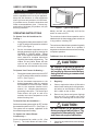
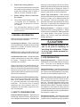
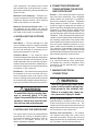
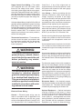
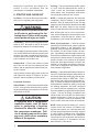
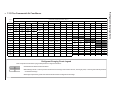
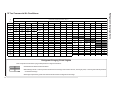
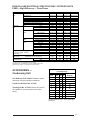
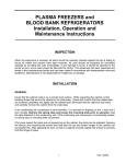
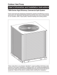
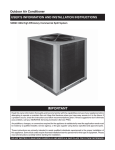
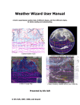
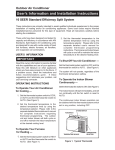
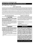
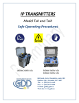
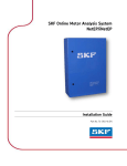
Outdoor Air Conditioner
User's Information and Installation Instructions
S3BM Series High Efficiency Commercial Split System
These units have been designed and tested for capacity and efficiency in
accordance with A.R.I. Standards. Split System Heat Pump units are designed
for use with a wide variety of fossil fuel furnaces, electric furnaces, air handlers,
and evaporator coil combinations.
These instructions are primarily intended to assist qualified individuals experienced in the proper installation of heating and/or air conditioning appliances.
Some local codes require licensed installation/service personnel for this type of
equipment. Read all instructions carefully before starting the installation.
USER’S INFORMATION
SYSTEM SWITCH
FAN SWITCH
IMPORTANT
TEMPERATURE
SELECTOR
Read this owner information to become familiar
with the capabilities and use of your appliance.
Keep this with literature on other appliances
where you have easy access to it in the future.
If a problem occurs, check the instructions and
follow recommendations given. If these suggestions don’t eliminate your problem, call your
servicing contractor .
OPERATING INSTRUCTIONS
To Operate Your Air Conditioner for
Cooling —
1.
2.
Set the thermostat system switch to COOL
or AUTO and the thermostat fan switch to
AUTO. (See Figure 1)
Set the thermostat temperature to the
desired temperature level by pressing the
WARMER or COOLER button. Please
refer to the separate detailed thermostat
user's manual for complete instructions
regarding thermostat programming. The
outdoor unit and indoor blower will both
cycle on and off to maintain the indoor
temperature at the desired cooling level.
To Operate Your Furnace for Heating —
1.
Set the thermostat system switch to HEAT
or AUTO and the thermostat fan switch to
AUTO. (See Figure 1)
2.
Set the thermostat temperature to the
desired temperature level by pressing
the WARMER or COOLER button. Please
refer to the separate detailed user's
manual for complete thermostat programming instructions. The furnace and
indoor blower will cycle on and off to
maintain the indoor temperature at the
desired heating level.
TEMPERATURE SCALES
Figure 1. Typical Thermostat
diately, and will run continually until the fan
switch is reset to AUTO.
The continuous indoor blower operation can be
obtained with the thermostat system switch set
in any position, including OFF.
The continuous indoor blower operation is typically
used to circulate the indoor air to equalize a
temperature unbalance due to a sun load, cooking,
or fireplace operation.
To Maintain Your Air Conditioner —
! CAUTION:
Be certain the electrical power to
the outdoor unit and the furnace/
air handler is disconnected before
doing the following recommended
maintenance.
1.
Regularly:
a.
Clean or replace the indoor air filter at the
start of each heating and cooling season,
and when an accumulation of dust and
dirt is visible on the air filter.
b.
Remove any leaves and grass clippings
from the coil in the outdoor unit, being
careful not to damage the aluminum fins.
To Shut Off Your Air Conditioner —
Set the thermostat system switch to OFF and the
thermostat fan switch to AUTO. (See Figure 1).
The system will not operate, regardless of the
thermostat temperature setting.
To Operate the Indoor Blower
Continuously —
Set the thermostat fan switch to ON (See
Figure 1). The indoor blower will start imme2
! CAUTION:
Do not over-oil, or oil motors not
factory-equipped with oil tubes. The
compressor is hermetically “sealed”
and does not require lubrication.
c.
Check for any obstructions, such as twigs,
sticks, etc.
2.
Before Each Cooling Season:
If the furnace/air handler blower motor and
the outdoor unit fan motor(s) have oil tubes
at the motor bearings, apply 10 drops of
SAE No. 20 motor oil to each oil tube.
3.
Before Calling a Service Technician,
Be Certain:
a.
The unit thermostat is properly set — see
“To Operate Your Air Conditioner for
Cooling” and “To Operate Your Furnace
for Heating.”
b.
The unit disconnect fuses are in good
condition, and the electrical power to the
unit is turned on.
1. GENERAL INFORMATION
Read the following instructions completely before performing the installation.
Condensing Unit Section — Each condensing
unit is shipped with a refrigerant holding charge
adequate to maintain a positive pressure to
keep out contaminants.
NOTE: DO NOT USE ANY PORTION OF THE
CHARGE FOR PURGING OR LEAK TESTING.
Liquid and Suction Lines — Refrigerant grade
copper tubing should be used when installing
the system. Refrigerant suction line tubing
should be fully insulated.
When condensing unit is matched with two air
handlers (two coils) or a dual circuited evaporator coil, refrigerant tubing should be branched
between both evaporator coils or circuits using
equal lengths of tubing to maintain equal evaporator/circuit performance.
Field Connections for Electrical Power Supply — All wiring must comply with current provisions of the “National Electrical Code” (ANSI
C1.) and with applicable local codes having
jurisdiction. The minimum size of electrical
conductors and circuit protection must be in
compliance with information listed on the outdoor unit data label.
servicing of this equipment should be accomplished by qualified, trained personnel thoroughly
familiar with this type of equipment. Under no
circumstances should non-qualified personnel attempt to install and/or service the equipment.
Labels, Tags, Precautions — When working
with this equipment, follow all precautions in the
literature, on tags, and on labels provided with
the equipment. Read and thoroughly understand the instructions provided with the equipment prior to performing the installation and
operational checkout of the equipment.
Brazing Operations — Installation of equipment may require brazing operations. Safety
codes must be complied with. Safety equipment
(e.g.; safety glasses, work gloves, fire extinguisher, etc.) must be used when performing
brazing operations.
! CAUTION:
Ensure all electrical power to the
unit is off prior to installing or
servicing the equipment. Failure
to do so may cause personal injury or death.
3. SITE PREPARATION
Unpacking Equipment — Remove the cardboard carton and User's Manual from the equipment. Take care not to damage the tubing
connections when removing the carton.
Inspect for Damage — Inspect the equipment for
damage prior to installing the equipment at the job
site. Ensure coil fins are straight and, if necessary,
comb fins to remove flattened and bent fins.
2. SAFETY CONSIDERATIONS
Preferred Location of the Outdoor Unit at Job
Site — Conduct a survey of the job site to determine the optimum location for mounting the outdoor unit. Overhead obstructions, poorly ventilated areas, and areas subject to accumulation of
debris should be avoided. The outdoor unit should
be installed no closer than 18 inches from the
outside walls of the facility and in an area free from
overhead obstructions to ensure unrestricted airflow through the outdoor unit.
Pressures within the System — Split system air
conditioning equipment contains liquid and gaseous refrigerant under pressure. Installation and
Facility Prerequisites — Electrical power must
be supplied to the equipment. Electrical power
supplied must be adequate for proper operation
3
of the equipment. The system must be wired
and provided with circuit protection in accordance with local building codes and the National
Electrical Code.
Minimum Circuit Ampacity — Electrical wiring to the equipment must be compatible and in
compliance with the minimum circuit ampacity
listed on the outdoor unit data label.
Maximum Fuse/Circuit Breaker Size — Circuit protection for the outdoor unit must be
compatible with the maximum fuse/circuit breaker
size listed on the outdoor unit data label.
4. INSTALLING THE OUTDOOR
UNIT
Slab Mount — The site selected for a slab
mount installation requires a stable foundation
and one not subject to erosion. The slab should
be level and anchored (if necessary) prior to
placing the equipment on the slab.
Cantilever Mount — The cantilever mount
should be designed with adequate safety factor
to support the weight of the equipment, and for
loads subjected to the mount during operation.
Installed equipment should be adequately secured to the cantilever mount and levelled prior
to operation of the equipment.
Roof Mount — The method of mounting should
be designed so as not to overload roof structures nor transmit noise to the interior of the
structure. Refrigerant and electrical line should
be routed through suitably waterproofed openings to prevent water leaking into the structure.
! WARNING:
To avoid the risk of property damage or personal injury, it is the
rigger's responsibility to ensure that
whatever means are used to hoist
the unit are safe and adequate.
5. INSTALLING THE INDOOR UNIT
The indoor section should be installed before
proceeding with routing of refrigerant piping.
Consult the installation instructions of the indoor unit (i.e.: air handler, furnace, etc.) for
details regarding installation.
4
6. CONNECTING REFRIGERANT
TUBING BETWEEN THE INDOOR
AND OUTDOOR UNIT
General — Once outdoor and indoor unit placement has been determined, route refrigerant
tubing between the equipment in accordance
with sound installation practices. Refrigerant
tubing should be routed in a manner that minimizes the length of tubing and the number of
bends in the tubing. Refrigerant tubing should be
supported in a manner that the tubing will not
vibrate or abrade during system operation. Tubing should be kept clean of foreign debris during
installation. Every effort should be made by the
installer to ensure that the field installed refrigerant containing components of the system have
been installed in accordance with these instructions and sound installation practices so as to
insure reliable system operation and longevity.
The maximum recommended interconnecting
refrigerant line length is 75 feet, and the vertical
elevation difference between the indoor and outdoor sections should not exceed 20 feet.
Optional Equipment — Optional equipment
(e.g.: liquid line solenoid valves, twinning kit,
low ambient,etc.) should be installed in strict
accordance with the manufacturer’s installation instructions.
7. MAKING ELECTRICAL
CONNECTIONS
! WARNING:
Turn off all electrical power at the
main circuit box before wiring electrical power to the outdoor unit.
Failure to comply may cause severe personnel injury or death.
Wiring Diagram/Schematic — A wiring diagram/schematic is located on the inside cover
of the electrical box of the outdoor unit. The
installer should become familiar with the wiring
diagram/schematic before making any electrical connections to the outdoor unit.
Outdoor Unit Connections — The outdoor
unit requires both power and control circuit
electrical connections. Refer to the unit wiring
diagram/schematic for identification and location of outdoor unit field wiring interfaces.
Supply Control Circuit Wiring — The outdoor
unit is equipped with a 24 VAC Class ll transformer for low voltage circuit control. Control
circuit wiring must comply with the current provisions of the “National Electrical Code” (ANSI C1.)
and with applicable local codes having jurisdiction. When using two air handlers, a twinning kit
(917453) is required for proper low voltage control wiring.
Units are shipped factory wired for 240 or 460 volt
operation (see unit data label for proper incoming
field wiring). For 208 volt operation, remove the
lead from the transformer terminal marked 240V
(on 208-230 models only) and connect it to the
terminal marked 208V. For maximum circuit
ampacity and maximum overcurrent protection,
see the unit rating plate.
Thermostat Connections — Thermostat connections should be made in accordance with
the instructions supplied with the thermostat,
and with the instructions supplied with the
indoor equipment.
! WARNING:
To avoid the risk of electrical shock,
personal injury, or death, disconnect all electrical power to the unit
before performing any maintenance or service.
! WARNING:
The unit cabinet must have an uninterrupted or unbroken electrical
ground to minimize personal injury
if an electrical fault should occur.
This ground may consist of electrical wire or approved conduit when
installed in accordance with existing national or local codes.
Electrical Power Wiring:
General — Electrical power wiring must be
made in accordance with all applicable local
codes and ordinances, and with the current
revision of the National Electric Code NFPA 70
or in Canada CSA C.22.1 Canadian Electrical
Code Part 1. If any of the original wire as
supplied with the unit must be replaced, it must
be replaced with material of the same gauge
and temperature rating.
Line Voltage — Before proceeding with the
electrical connections, make certain that the
voltage, frequency and phase of the supply
source are the same as those specified on the
unit rating plate. Also verify that the service
provided by the utility is sufficient to handle the
additional load imposed by this equipment.
This unit must be electrically grounded in accordance with local codes or, in the absence of local
codes, with the National Electrical Code (ANSI/
NFPA 70) or the CSA C22.1 Electrical Code.
See the unit wiring label for proper high and low
voltage wiring. Make all electrical connections
in accordance with all applicable codes and
ordinances.
Use a separate branch electrical circuit for this
unit. A means of electrical disconnect must be
located within sight of and readily accessible to
the unit.
Overcurrent protection must be provided at the
branch circuit distribution panel and sized as
shown on the unit rating label and according to
the National Electric Code and applicable local
codes.
Provide power supply for the unit in accordance
with the unit wiring diagram, and the unit rating
plate. Connect the line-voltage leads to the terminals on the contactor inside the control compartment. Use only copper wire for the line voltage
power supply to this unit. Use proper code agency
listed conduit and a conduit connector for connecting the supply wires to the unit. Proper grounding is accomplished by using the grounding lug
provided in the control box.
Disconnect Switch — An electrically compatible disconnect switch must be within line of sight
of the outdoor unit. This switch shall be capable
of electrically de-energizing the outdoor unit.
Optional Equipment — Optional equipment
requiring connection to the power or control
circuits must be wired in strict accordance with
current provisions of the “National Electrical
Code” (ANSI C1.), with applicable local codes
having jurisdiction, and the installation instructions provided with the equipment. Optional
Equipment (e.g.: liquid line solenoid valves,
5
twinning kit, low ambient, etc.) should be installed in strict accordance with the
manufacturer’s installation instructions.
8. STARTUP AND CHECKOUT
Air Filters — Ensure air filters are clean and in
place prior to operating the equipment.
! WARNING:
Ensure electrical power to the unit
is off prior to performing the following steps. Failure to do so may
cause personal injury or death.
Thermostat — Set the room thermostat function
switch to OFF, fan switch to AUTO, and move
temperature setpoint to its highest setting.
Prior to applying electrical power to the outdoor
unit, ensure that the unit has been properly and
securely grounded, and that power supply connections have been made at both the facility
power interface and outdoor unit.
Outdoor Unit — Ensure the outdoor coil and
top of the unit are free from obstructions and
debris, and all equipment access/control panels are in place.
Using extreme caution, apply power to the unit
and inspect the wiring for evidence of open,
shorted, and/or improperly wired circuits.
Functional Checkout:
Indoor Blower — Set the thermostat fan switch
to ON. Verify that the indoor blower is operating and that airflow is not restricted. Set the fan
switch back to AUTO.
! CAUTION:
If equipped with a compressor
crankcase heater, wait 24 hours
prior to performing a function
checkout to allow for heating of
the compressor crankcase. Failure to comply may result in damage and could cause premature
failure of the system.
6
Cooling — Set the thermostat system switch
to “Cool” and the thermostat fan switch to
“Auto.” Lower the thermostat temperature
switch below room temperature and ensure
unit refrigerant pressures are in order.
NOTE: If refrigerant pressures are abnormal,
compressor may be rotating in the opposite
direction. Shut off main power to the unit and
switch any two field wires at the disconnect. DO
NOT alter unit wiring. Listen for any unusual
noises. Locate the source and correct as needed.
After allowing the unit to run for several minutes, set the temperature selector above room
temperature, verify that the fan, blower, and
compressor cycle off with the thermostat.
Short Cycle Protection — With the system
operating in COOLING mode, note the setpoint
temperature setting of the thermostat, and
gradually raise the setpoint temperature until
the outdoor unit and indoor blower de-energize. Immediately lower the setpoint temperature of the thermostat to its original setting and
verify that the indoor blower is energized and
that the outdoor unit remains de-energized.
Verify that, after approximately 5 minutes, the
outdoor unit energizes and that the temperature of the air supplied to the facility is cooler
than ambient temperature.
Heating — If provided with heating equipment,
lower the thermostat setpoint temperature to
the lowest obtainable setting and set the thermostat function switch to HEATING. The indoor blower and outdoor unit should stop running. Increase the setpoint temperature of the
thermostat to the maximum setting. Verify that
the heating equipment has been energized
(i.e., fossil fuel burner operating, etc.) and that
the indoor blower energizes after a short period
of time. Feel the air being circulated by the
indoor blower and verify that it is warmer than
ambient temperature. Listen for any unusual
noises. If present, locate and determine the
source of the noise and correct as necessary.
NOTE: Other sources for heating (i.e.: electric
furnace, fossil fuel furnace, air handler with
electric heat options, etc.) that interface with
the heat pump should be functionally checked
to verify system operation and compatibility
with the heat pump. Refer to the installation
instructions for this equipment and perform a
functional checkout in accordance with the
manufacturer’s instructions.
Preliminary Orifice Usage
9 EER Commercial Air Conditioner
Model
Number
Restrictor
Size (in.)
7 1/2 Ton
0.082
10 Ton
0.093
Adjustment of Refrigerant Charge:
! CAUTION:
Split system air conditioning
equipment contains liquid and
gaseous refrigerant under pressure. Adjustment of refrigerant
charge should only be attempted
by qualified, trained personnel
thoroughly familiar with the equipment. Under no circumstances
shouldthe homeowner attempt to
install and/or service this equipment. Failure to comply with this
warning could result in equipment
damage, personal injury, or death.
NOTE: The following Refrigerant Charging
Charts are applicable to matched assemblies
of our equipment and at listed airflows for the
indoor coil. Assemblies of indoor coils and
outdoor units not listed are not recommended
and deviations from rated airflows or nonlisted equipment combinations may require
modifications to the expansion device(s) and
refrigerant charging procedures for proper
and efficient system operation.
Refrigerant Charging Chart — Refer to Refrigerant Charging Charts for correct system
charging, and to Orifice Usage Chart for correct
restrictor sizes.
Optional Equipment — A functional checkout should be performed in accordance with
the checkout procedures supplied with the
equipment.
7
7-1/2
O UT D O O R T E M P E R A T UR E ( deg. F )
TON
70
75
80
85
95
90
100
105
S u c . P re s s L iq . P re s s . D is . T e m p . L iq . P re s s . D is . T e m p . L iq . P re s s . D is . T e m p . L iq . P re s s . D is . T e m p . L iq . P re s s . D is . T e m p . L iq . P re s s . D is . T e m p . L iq . P re s s . D is . T e m p . L iq . P re s s . D is . T e m p .
63
165
95
65
167
106
179
113
67
168
117
181
123
194
129
69
170
129
183
133
196
138
210
143
71
172
136
185
143
199
147
213
151
188
152
203
153
216
159
230
163
244
167
205
166
220
166
234
170
248
174
262
178
222
178
237
179
252
180
266
184
280
188
239
189
73
75
77
79
226
155
254
190
270
190
285
193
81
257
200
272
201
289
199
83
259
210
274
210
289
212
277
220
292
221
294
230
85
87
89
Refrigerant Charging Charts Legend
*Note: All pressures are listed in psig, all temperatures in degrees Fahrenheit.
– Shaded boxes indicate flooded conditions
– Rated Design Values. Suction pressure will be lower than design value if indoor air flow, entering dry bulb, or entering wet bulb temperatures
are lower than design.
– Discharge temperatures greater than charted values indicate a refrigerant undercharge.
Refrigerant Charging Charts
8
7-1/2 Ton Commercial Air Conditioner
10
O UT D O O R T E M P E R A T UR E ( deg. F )
TON
70
75
80
85
90
95
100
105
S u c . P re s s L iq . P re s s . D is . T e m p . L iq . P re s s . D is . T e m p . L iq . P re s s . D is . T e m p . L iq . P re s s . D is . T e m p . L iq . P re s s . D is . T e m p . L iq . P re s s . D is . T e m p . L iq . P re s s . D is . T e m p . L iq . P re s s . D is . T e m p .
58
178
162
60
180
174
191
191
62
181
185
194
201
206
64
182
197
196
211
209
225
222
240
66
185
202
198
221
212
234
225
248
239
262
200
229
215
240
229
256
242
269
256
283
217
253
232
263
246
276
260
289
274
303
234
274
249
285
264
296
278
309
292
322
251
295
68
70
216
72
74
266
306
282
315
296
328
76
269
316
284
326
301
334
78
271
326
286
336
301
346
288
345
304
355
306
364
80
82
84
Refrigerant Charging Charts Legend
*Note: All pressures are listed in psig, all temperatures in degrees Fahrenheit.
– Shaded boxes indicate flooded conditions
– Rated Design Values. Suction pressure will be lower than design value if indoor air flow, entering dry bulb, or entering wet bulb temperatures
are lower than design.
– Discharge temperatures greater than charted values indicate a refrigerant undercharge.
Refrigerant Charging Charts
10 Ton Commercial Air Conditioner
9
10
Notes: 1) Disconnect all power before servicing.
2) For supply connections use copper conductors only.
3) Furnace/Air Handler w/factory equipped 24 V control circuit transformers, should be
modified/rewired to ONLY use 24V transformer from outdoor section. See installation
instructions for typical modifications.
4) For replacement wires use conductors suitable for 105˚ C.
5) For ampacities and overcurrent protection, see unit rating plate.
L1
L2
CC
L3
CC
CC
BLACK
BLACK
OUTDOOR FAN
MOTOR
S
1) Couper le courant avant de faire letretien.
2) Employez uniquement des conducteurs en cuivre.
RED
CCH
C
T3
T2
R
CONTACTOR
BLACK
LOW PRESSURE
SWITCH
BLACK
T1
HIGH PRESSURE
SWITCH
YELLOW
COMPRESSOR
T2
COMPRESSOR
T3
T1
T2
T3
L1
L2
L3
BLACK
PURPLE
T1
GREEN
YELLOW
BLACK
C
S
R
RED
BLACK
PURPLE
ORANGE
ASCT
CC
ASCT
R
Y
HIGH PRESSURE
SWITCH
WHITE
OUTDOOR FAN
MOTOR
LOW PRESSURE
SWITCH
C
Field Wiring
High Voltage
Low Voltage
Factory Wiring
High Voltage
Low Voltage
BLACK
3-PHASE SUPPLY
VOLTAGE
ANTI-SHORTCYCLE TIMER
R
Y C
ISOLATED T-STAT CONTACT
24V FOR INDOOR
CONTROL CIRCUIT
7039770
PHYSICAL AND ELECTRICAL SPECIFICATIONS / OUTDOOR UNITS
9 EER —High Efficiency — Three Phase
Model No. S3BMElectrical
Data
Volts-Phase-Hz
Voltage Range (Min-Max)
Total Amps
Min. Circuit Ampacity
Delay Fuse Max. (1)
Wire Size/Max Length (AWG 60°C Cu)
Wire Size/Max Length (AWG 75°C Cu)
Component
Coil
Area
Data
Rows-FPI
Tube Dia.
Fan
Motor
Volts-Phase-Hz
Qty
Horsepower
Full Load LRA
Fan
Dia./Pitch/#Blades
Blade
RPM/CFM (Max-Total)
Compressor
Voltage-Phase-Hz
Data
Qty./Type
RLA
LRA
Stages/Percent
Crankcase Heater Qty./Type
Refrigerant Suction Line-Length/O.D.
0 - 15 ft.
(Liq. Line All Lengths - 5/8"O.D.)
16 - 25 ft.
Circuits (Qty) - 1
26 - 75 ft.
Refrigerant Charge
Holding
R-22 Ounces
Total System with 15' Line Set (2)
Weight
Net
Approximate (lbs.)
Ship
090C
208/230-3-60
187-253
34.2
41.4
70
4
6
31.94
1-22
3/8 O.D.
208/230-1-60
1
1
5.4
26 / 28 / 4
1060 / 5500
208/230-3-60
1 / Scroll
28.8
195
1 / 100
1 / Band
1 1/8"
1 1/8"
1 1/8"
56
288
325
362
090W
460-3-60
380/420-3-50
414-506
17.2
20.9
35.0
8
8
31.94
1-22
3/8 O.D.
460-1-60
380/420-1-50
1
1
2.5
26 / 28 / 4
1060 / 5500
460-3-60
1 / Scroll
14.7
95
1 / 100
1 / Band
1 1/8"
1 1/8"
1 1/8"
56
288
325
362
120C
208/230-3-60
187-253
43.1
52.5
90.0
2
3
31.94
1-22
3/8 O.D.
208/230-1-60
1
1
5.4
26 / 28 / 4
1060 / 8000
208/230-3-60
1 / Scroll
37.7
239
1 / 100
1 / Band
1 1/8"
1 1/8"
1 3/8" (3)
76
304
341
378
120W
460-3-60
380/420-3-50
414-506
19.7
24
40
8
8
31.94
1-22
3/8 O.D.
460-1-60
380/420-1-50
1
1
2.5
26 / 28 / 4
1060 / 8000
460-3-60
1 / Scroll
17.2
125
1 / 100
1 / Band
1 1/8"
1 1/8"
1 3/8" (3)
76
304
341
378
(1) HACR Type Circuit Breakers may be used.
(2) Add 9.0 oz. of refrigerant per 5 foot of additional line set.
(3) Requires 1-3/8" to 1-1/8" reducer from unit toline.
ACCESSORIES —
Condensing Unit
Low Ambient Kit 913549A- Maintains system
pressures during low ambient conditions.
Liquid Line Solenoid Kit - 917452
Twinning Kit B3 - 917453 Used to twin two B3
air handlers for common power and control
wiring.
COPPER WIRE SIZE — AWG
(1% Voltage Drop)
Supply Wire Length-Feet Supply Circuit
200
150
100
50
Ampacity
6
8
10
14
15
4
6
8
12
20
4
6
8
10
25
4
4
6
10
30
3
4
6
8
35
3
4
6
8
40
2
3
4
6
45
2
3
4
6
50
2
3
4
6
55
1
2
3
4
60
Wire Size based on N.E.C. for 60° type copper
conductors.
11
INSTALLER:
PLEASE LEAVE THESE INSTALLATION
INSTRUCTIONS WITH THE HOMEOWNER
¢707809G¤
707809A
707809A (Replaces 7078090)
RT
IF IE
D T O AR
I A
S
R
TA
A
R
UI P M E N T
I S
TA
NDA R D
0
24
G W I TH
MP
UNI
PU
UF
M A N A C TU R
T
¨
EQ
R
N
LY I
A
MP
HE
Y
C
O
ER
CE
Specifications and illustrations subject to change
without notice and without incurring obligations.
Printed in U.S.A. (2/00)