1
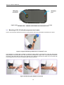
91-92 Shrivenham Hundred Business Park, Oxfordshire, SN6 8TY Telephone: 01793 780 622 Email: [email protected] Product Information below: SV 103 USER'S MANUAL________________________________________________________ _ SV Daily Vibration Exposure Meter USER’S MANUAL SVANTEK Sp. z o.o. 1 SV 103 USER'S MANUAL________________________________________________________ _ WARSAW, September 2014 Notice: The SV103 instrument contains no user serviceable parts. Opening product case invalidates the warranty. Notice: Battery power indicator - To improve accuracy of remaining battery life indicator, run the instrument until it is fully discharged; then proceed with a full charge via the micro USB port. The procedure is recommended before first use. Repeat this procedure every few months of use to maintain more accurate current battery condition indication. Notice: On account of continuous product improvement SVANTEK reserves the right to make changes to product specifications without notice. To download the most up to date user's manual please visit our web site at www.svantek.com. This user’s manual presents the firmware revision named 1.07.1 (see the Unit Label review to check version details). This user’s manual presents some aspects of SUPERVISOR software revision named 1.4.4 (see the software start-up splash screen). The succeeding software revisions (marked with the higher numbers) can change the view of some displays presented in the text of the manual. WEEE Notice: Do not throw the device away with the unsorted municipal waste at the end of its life. Instead, hand it in at an official collection point for recycling. By doing this you will help to preserve the environment. Trademarks Microsoft and Windows are registered trademarks of Microsoft Corporation Copyright © 2014, SVANTEK sp. z o.o. All rights reserved. No part of this publication may be reproduced or distributed in any form, or by any means, without prior written consent from SVANTEK, Warsaw, Poland 2 SV 103 USER'S MANUAL________________________________________________________ _ CONTENTS 1 INTRODUCTION 5 1.1 Vibration risk and it’s assessment 5 1.2 SV 103 as a new generation vibration exposure meter 6 2 SV 103 SYSTEM DESCRIPTION 7 2.1 SV 103 key features 7 2.2 Kit components 7 2.3 Related equipment & accessories 8 2.4 Instrument Software (Firmware) options available 8 3 GETTING STARTED 9 3.1 SV 103 control panel 9 3.2 Input output interfaces description 9 3.3 Mounting of SV 103 vibration exposure level meter 10 3.4 LED status indicator 11 3.5 Status bar icons 11 3.6 Manual control of the instrument 11 3.6.1 Primary key functions 12 3.6.2 Alternate key functions 13 3.6.3 Alternate combined keys function 14 3.7 Charging 14 3.8 Turning on/off 15 3.9 Starting and stopping measurement run 16 4 RUNNING AND OPERATING BASIC PROCEDURES 4.1 The VIEW mode presentation concept 17 17 4.1.1 Running RMS view mode 17 4.1.2 Primary “ONE-RESULT” parameters view mode 17 4.1.3 Results for channels view mode 18 4.1.4 OCTAVE analysis spectrum view mode 18 4.1.5 Instrument Status view mode 19 4.1.6 File information view mode 20 4.2 ALARM screen review 20 4.3 Reviewing unit label 20 4.4 Loading Measurement Setups 21 4.5 Calibration and verification of the instrument 21 4.5.1 Calibration the Instrument 22 4.5.2 Verification the Instrument’s calibration 23 4.5.3 Calibration the contact forces transducer 24 4.6 Auto-run mode information 25 4.7 Security lock 25 4.8 Measurement procedures 26 3 SV 103 USER'S MANUAL________________________________________________________ _ 4.9 Reviewing measurements 5 27 BASIC OPERATIONS WITH THE PC SOFTWARE 28 5.1 Installing and connecting to PC 28 5.2 Main software window 29 5.3 Instruments inventory panel 30 5.3.1 Manage the instrument options 31 5.4 Configuration setup 32 5.4.1 Working with configuration setup files 32 5.4.2 Measurement parameters settings tab 36 5.4.3 Triggering settings tab 37 5.4.4 Time-history data logging settings tab 38 5.4.5 Display VIEW configuration tab 39 5.4.6 General settings tab 5.4.6.1 Security settings panel 5.4.6.2 Auxiliary settings panel 40 41 42 5.4.7 Auto-Run settings (timer, pauses) tab 43 5.4.8 Signal recording options tab 5.4.8.1 Recording on trigger 5.4.8.2 Continuous recording 44 44 44 5.5 Working with data files 45 5.5.1 Downloading instrument files 45 5.5.2 Local files “Data Browser” 46 5.6 Working with sessions and reporting 48 6 5.6.1 Force threshold slider 50 5.6.2 Report panels 50 SV103 MAINTENANCE 54 6.1 General recommendations for use 54 6.2 Cleaning 54 6.3 Changing the accelerometer 54 6.4 Firmware upgrade 54 6.5 Storing the instrument 55 6.6 Transportation and carrying 55 7 SVANTEK SERVICE 56 7.1 Troubleshooting 56 7.2 Resetting the instrument 56 4 SV 103 USER'S MANUAL________________________________________________________ _ 1 INTRODUCTION 1.1 Vibration risk and it’s assessment During human contact with the surface of the vibrating machine, mechanical vibrations are transmitted directly to the human body, affecting the individual tissues or even the whole body. Vibration that affects humans is called human vibration and is divided into whole-body and hand-arm vibration. In practice, the most dangerous are hand-arm vibrations which can cause pathological changes in the nervous, vascular (cardiovascular) and osteoarticular system. Hand-arm vibration occurs when one or both of the upper limbs is in contact with a vibrating surface. Typical sources of such vibration are any kind of hand tools that generate vibration, steering wheels and levers to control vehicles. The characteristic feature of hand-arm vibration is their variability in time. Therefore, very often, measurement results depend on the point in time that measurement takes place. This is a very important feature that defines both the test methods and measurements describing this kind of vibration. This variability in time influences another significant factor in determining the body's response to the vibration which is the exposure time (duration of exposure to vibration). The fundamental parameter used in the evaluation of hand-arm vibration is the vector sum of tri-axial vibration called AEQ which is the basis for the calculation of daily exposure A(8). To identify the daily exposure it is necessary to identify all the sources of vibration, which means identifying all working modes of tools (e.g. drilling with hammer and without), and changes in the conditions of use of the device. This information is necessary for the proper organization of measurement and to include as many common tasks of the operator during which he is exposed to hand-arm vibration. Daily exposure should be calculated for each source of vibration. After determining the sources of mechanical vibrations affecting the employee, the next step is to choose the most appropriate accelerometer mounting. According to ISO 5349, hand-arm vibration should be measured in place, or at the point of contact with the hand tool. The best location is the centre of the handle which is the most representative location. ISO 5349 suggests using lightweight sensors to reduce measurement errors. Measurements directly at the hand are performed using special adapters and measurement in all three axes is recommended. Typical vibration exposure consists of short periods in which the operator is in contact with the tool. Measuring time should include a representative tool operation time and the measurement should start from the moment the vibrating device is touched and should end when the contact is broken or the vibration stops (ISO 5349-2:2001). 5 SV 103 USER'S MANUAL________________________________________________________ _ 1.2 SV 103 as a new generation vibration exposure meter SV 103 is the first ever made personal hand-arm Daily Vibration Exposure Meter (DVEM). Instrument meets ISO 8041 standard and it is an ideal choice for the measurements according to ISO 5349. The SV 103 is typically attached to the user’s arm. Similarly to noise dosimeters, SV 103 daily vibration exposure meter is small enough not to interfere with working activities. New technology of SV 107 accelerometer gives advantages such as shock resistance, no DC offset effect, very low power and frequency response down to DC. Inside the hand adapter is the latest MEMS accelerometer and a contact force sensor. Contact forces act between the hand and the vibrating surface: the push/pull force and the gripping force. Studies on the hand-arm vibration prove that contact forces modify exposure to vibration and the health effects it causes The need of simultaneous assessment of the contact forces and vibration magnitudes has been universally recognized and reflected in ISO 15230. Figure 1-1 Examples of contact forces measurement given by ISO 15230 The high resolution colour OLED screen displays information in both text and graphical form and offers excellent visibility in dark sites as well as in full daylight conditions. Using the computational power of its digital signal processor the SV 103 instrument can simultaneously measure the all results (RMS, Max, Peak, Peak-Peak, Vector, A(8), Dose, ELV, EAV) simultaneously in three channels and perform real time 1/1 Octave or 1/3 Octave analysis. Advanced time history logging provides safe and complete information about measured signal in the internal large 8GB memory. The instrument is powered from internal new generation Ni-MH rechargeable batteries offering circa 30 hours of continuous operation. The powering and charging of the instrument from the USB interface is provided which also enables easy data exchange connection between the SV 103 and a PC without the requirement of a special docking station. The instrument works with “Supervisor” PC software which allows instrument configuration, measurement results viewing and exporting as well as daily vibration exposure recalculation. 6 SV 103 USER'S MANUAL________________________________________________________ _ 2 SV 103 key features 2.1 2.2 SV 103 SYSTEM DESCRIPTION • Hand-arm Personal human vibration meter conforming to ISO 8041:2005 standard; • Measurement under gloves • SV 107 hand-arm triaxial MEMS accelerometer including hand straps according to ISO 5349-2 • OLED colour display with super brightness and contrast • Large 8GB memory • USB 2.0 high speed interface • In order to comply with ISO 5349-1:2001, the input signals from all measurement channels are frequency weighted with the Wh weighting filters and corresponding Band Limiting filter • Digital true RMS detector with Peak detection, resolution 0.1 dB • Frequency Range 1 Hz ÷ 2 kHz • Measurement range 0.2 ms RMS ÷ 2000 ms Peak • Simultaneous measurement results: PEAK, P-P, RMS, AEQ, CExp, A(8), EAVTT, AEVTL, ELVTT, ELVTL, OVL, Fmax, F_1s, Fave, FUT, TIME • 3 user configurable measurement channels • Easy in use predefined setups • Time-history data logging of PEAK/P-P/RMS/Vector/Force with variable 0.1 s to 1 h logger step for three channels • Time-domain signal recording (optional) • 1/1 Octave or 1/3 Octave real time analysis (option) • Operational time > 30 hours (display off, octave analysis off) • Extremely compact, lightweight and robust case with IP65 ingress protection: dimensions 88 mm x 49.5x 19.2 mm, weight 150-160 grams with SV107 accelerometer and one of vibration contact adapters -2 -2 Kit components • SV 107 – hand-arm triaxial accelerometer for SV 103 instrument including hand straps • SC 156 - micro USB 2.0 cable • CD with instruction • Built-in rechargeable batteries (charger/ power supply wall adapter not included) The following Figure 3- shows the SV 103 standard set and way of mounting. 7 SV 103 USER'S MANUAL________________________________________________________ _ Mounting accessories SV 107 hand-arm triaxial accelerometer Figure 2-1 SV 103 standard mounting set 2.3 Related equipment & accessories Accessories • SA 54 – Charger/power supply for 1 x SV 103 • SA 156 – USB HUB for charging and data download from 5 x SV103 instruments • Supervisor Software for configuration, viewing and exporting data, USB drivers (MS Windows XP, Vista, Windows 7) for 32 and 64 bit operating systems available as freeware Related equipment and accessories • SV 111 –Vibration calibrator for in-situ check to ISO 8041:2005 • SA 73 - Carrying case for SV 103 instrument and accessories (waterproof) 2.4 Instrument Software (Firmware) options available • SF 103 OCT 1/1 –11 band 1/1 Octave real time analysis option • SF 103 OCT 1/3 –34 band 1/3 Octave real time analysis option • SF 103 WAV - Time Domain / Wave recording option Notice: The software options can be purchased in any time as only the introduction of a special code is required for their activation. 8 SV 103 USER'S MANUAL________________________________________________________ _ 3 GETTING STARTED 3.1 SV 103 control panel The following Figure 3-ure shows the SV 103 controls and ports: LED status indicator AMBER: stop mode GREEN: measuring RED: alarm Colour display 128 x 64 pixel resolution Keypad Figure 3-1 SV 103 view 3.2 Input output interfaces description SV 103 instrument is equipped with a set of useful interfaces: • accelerometer connector (essential for measuring) • micro USB connector (charging, and data download) • charging connector (reserved for future use) • fast infrared port (reserved for future use) accelerometer mounting head micro USB connector Figure 3-2 SV 103 side view – accelerometer and micro USB connector 9 SV 103 USER'S MANUAL________________________________________________________ _ charging connector infrared port Figure 3-3 SV 103 back view - charging and infrared port (reserved for future use) 3.3 Mounting of SV 103 vibration exposure level meter The SV 103 should be attached to the arm of the operator and the accelerometer mounted on the hand. Figure 3-4 Typical mounting of SV 103 on an operator’s arm The transducer is supplied with 3 adapters of different shape. Before measurements, select the appropriate shape adapter to the projected work, and unite it with the transducer using screws. The transducer should be mounted on the hand with the cable in the direction of the elbow as pictured The cable is to be secured with a mounting band on the wrist not interfering with working activities. Figure 3-5 Mounting the adapter on the hand 10 SV 103 USER'S MANUAL________________________________________________________ _ 3.4 LED status indicator There is a three-colour instrument LED status indicator on the SV 103, located to the right of the accelerometer mounting head and above the display. Błąd! Nie można odnaleźć źródła odwołania. explains conditions under which the specific LED colour appears. LED status indication GREEN flashing once per second AMBER flashing once per over a dozen seconds RED flashing quickly, four times per second Description Indicates the instrument is running and has not exceeded the alarm level. Indicates the instrument is stopped and has not exceeded the dose alarm level. Indicates the alarm conditions: for instance: the dose has exceeded the alarm level. 3.5 Status bar icons The upper part of the display is designed as basic status information provider. See the description below. current VIBRATION AXIS MEASUREMENT RUN flashing indicator LOGGER activation indicator UNDER-RANGE indicator BATTERY STATUS indicator incremental flashing during charging OVERLOAD indicator CURRENT TIME when in stopped mode or MEASURMENT TIME during measurement run. Figure 3-6 SV 103 display icons description 3.6 Manual control of the instrument Although the Instrument is small, its keypad is designed to be minimal, but still highly ergonomic and easy to use providing effective operational capabilities. Thanks to that, the number of the control push-buttons of the instrument is reduced to only three. Generally the user can operate the instrument by: - change the VIEW mode with the <ENTER> - select the required VIBRATION AXIS with the <AXIS> - and SCROLL thru the results with the key or key keys Notice: To save power consumption and extend battery life SV 103 will automatically switch off the display after 30 seconds if no button on the keypad is pressed. The LED indicator will still inform the user about the current state of operation and any possible alarm conditions. Press any key, to reactivate the display. 11 SV 103 USER'S MANUAL________________________________________________________ _ 3.6.1 Primary key functions On the front panel of the instrument the following control push-buttons are located. See below for primary (short press) key functions description: <SCROLL> key <SCROLL> key . <AXIS> key <ENTER> key Figure 3-7 Control keypad on the front panel – primary key functions The <SCROLL> - key allows to: change VIEW modes; enter different positions in the Calibration screens ; confirm changed parameters (for example, Level parameter in the Calibration axis screens). The <AXIS> - keys allow to: scroll down thru results in the RESULTS VIEW modes; move cursor left and right in the SPECTRUM VIEW modes; scroll down and up thru menu Calibration positions; scroll down and up thru setups in the Load Setup menu; decrease and increase the values of the Level parameter in the Calibration axis screens; reject or confirm Warnings or other confirmation messages. The <ENTER> - or key allows to: change presented vibration channels; escape from Load Setup and Calibration screens. 12 SV 103 USER'S MANUAL________________________________________________________ _ 3.6.2 Alternate key functions Alternative long press of single key (keypad icons marked with red colour) allows quick access to special functions: - POWER ON/OFF the unit by holding down the <ENTER> - Calibration menu activation by holding down the <SCROLL> key - LOCK keypad and screen by holding down the <SCROLL> - SETUP loading by holding down the <AXIS> key key key <SCROLL> key LOCK ON the keypad and screen <SCROLL> key Enter Calibration menu <CHANNEL> key Enter Load Setup screen <ENTER> key POWER on/off Figure 3-9 Control keypad on the front panel – alternate key functions Holding down individual key for few seconds a countdown is displayed. If you release the key too early, SV 103 returns to the last used VIEW mode and the selected control is not executed. 13 SV 103 USER'S MANUAL________________________________________________________ _ 3.6.3 Alternate combined keys function Additionally, combined short press of two keys simultaneously allow quick access to even more functionalities: - Start/Stop measurement by pressing the <SCROLL> keys simultaneously - Enter Pause screen by pressing the <ENTER> and and <SCROLL> keys simultaneously during the measurement run - Enter Units screen by pressing the <SCROLL> and <AXIS> keys simultaneously - Enter Unit Label screen by pressing the <ENTER> <AXIS> and keys simultaneously 3.7 Charging SV 103 instrument is equipped with an internal charger, so that the fixed internal batteries can be charged directly from USB port or optionally provided charger (SA 54). Ensure the SV 103 is fully charged prior to use by connecting it to a USB port or to USB charger. Ensure the power supply is connected and the supply is switched on. The SV 103 will automatically switch on during charging and display how much charge is within the instrument. The SV 103 will display ‘Fully charged’ once charging is complete. This should take approximately 6 hours from a fully discharged state. A charging time of about 2 hours will be sufficient to perform greater than 8 hours of measurement. A fully charged instrument holds enough charge to run for approximately 30 hours. Note that once disconnected from USB power supply, the instrument will automatically switch off. If returned to the USB connection or put again onto the docking station the instrument keeps trickle charging regardless of whether or not it is fully charged. This keeps the battery performance in steady condition. If the battery is fully discharged prior to being placed on a charger, the SV 103 trickle charges for a short time prior to the fast charge cycle, this prevents damage to the batteries. Notice: To charge a fully discharged battery, it would take approximately 4-6 hours. Note also, that instrument under charging condition is slightly warm. It is normal state for NiMH type cells and does not affect the measurement accuracy. 14 SV 103 USER'S MANUAL________________________________________________________ _ Notice: To charge multiple units at the same time via the USB port, ensure your computer or possibly the powered USB hub such as the SA 156 or switch is capable in terms of providing enough current performance. Standard hub or switches without external power supply are not capable to charge multiple SV103 units due to insufficient current supply. Current estimation: Assume the current consumption on 0.2A level, and calculate required power supply requirement (N x 0.2A). Power wattage estimation: With nominal voltage of 5V per USB, the power supply wattage should be 1.0W per unit (Nx1.0W). For example 5 units charged at once require: 1.0A/12.5W USB power supply For example 3 units charged at once require: 0.6A/7.5W USB power supply For example 1 unit charged alone requires: 0.2A/2.5W USB power supply Notice: Use only high quality USB cables. Many poor quality cables do not ensure low resistance of the cable, thus disabling proper charging of the internal cells. 3.8 Turning on/off TURNING ON: To switch the power on the operator should hold the <ENTER> key for a couple of seconds. The instrument switches on and goes the self-test routine (during this time the manufacturer's logo, the name of the instrument and firmware version is displayed). Then the SV 103 will enter the stopped (ready to measure) mode and enter the running instantaneous RMS mode if enabled. Notice: Warm up time - After power on, the instrument should be warmed up for at least 60 seconds before starting measurement. Notice: If you leave the instrument in stopped (ready to measure) mode, the display will be switched off after 30 seconds, and the unit will turn off after some period of no keypad activity to save the batteries. The above mentioned period can be program and is set up for 1 hour by default. Notice: SV 103 will show a warning screen if the battery capacity is below 2 hours of potential measurement time. TURNING OFF: To shut down the unit the operator should hold the <ENTER> key for a couple of seconds during which a countdown (“Shutting down” 3O 2O 1O ) is displayed. Thus, the SV 103 gives you time to decide if you really want to turn off the instrument. If you release the key too early, the SV 103 returns to the last presented VIEW mode. 15 SV 103 USER'S MANUAL________________________________________________________ _ If enabled in the configuration setup there may be presented an additional, double-check, warning screen. This is for the operator to be aware and convinced the unit is really to be turned off. Notice: If auto-run (timer) mode is active, SV 103 will automatically stop the measurement when the set time is over and then turn off. If no auto-run mode is used and specific time has not been preset, the unit will continue to measure until the battery is exhausted. Just before switch off, the measurement run will be stopped and all data until that point will be saved securely for later download to the PC. 3.9 Starting and stopping measurement run START: Before starting a measurement ensure that: 1 the instrument is turned on, 2 there is sufficient battery operating life and free memory by checking the status screen, 3 the required configuration setup selected, 4 the SV 103 is calibrated, because it affects the results. To start the measurements the user has to press the <SCROLL> and keys at the same time. The results of the measurement are displayed in the last used result’s display view mode. One profile mode is always available for most Functions of the instrument. The results of the measurements can also be presented in other display modes, which can be enabled or disabled and adjusted to the user’s needs. STOP: The same combination of keys: <SCROLL> and allows the user to stop the measurement run. All run results are always saved automatically, there is no need to save them manually. After stopping the measurement run, make sure that: 1 2 the data to PC for further analysis is download, the instrument turned off. 16 SV 103 USER'S MANUAL________________________________________________________ _ 4 RUNNING AND OPERATING BASIC PROCEDURES 4.1 The VIEW mode presentation concept Such an advanced vibration instrument as the SV 103 offers a large amount of parameters for the operator to inspect. Therefore all information is divided in neatly organized manner as VIEW modes for each channel. The VIEW mode is a way in which the measurement parameters are presented to the operator. In other words, when you change the VIEW mode, specific measurement parameters and status information will be presented in different manner as distinct screen content. SV103 features the following VIEW modes, where most of them can be individually disabled: Running RMS for three channels view mode Primary “one-result” parameters view mode - cannot be disabled Results for channels list view mode 1/1 and 1/3 Octave analysis RMS spectrum view mode 1/1 and 1/3 Octave analysis spectrum MAX view mode Instrument Status view mode File Information view mode 4.1.1 Running RMS view mode Running RMS presentation mode is used when measurement run is not actually running, that is when the instrument is in standby mode before or after a measurement. In this mode the current RMS results for all channels are calculated and displayed, but not stored in the instrument's memory. The purpose of this information is to give the user a first indication of the vibration levels about to be measured. The instrument behaves as a simple general purpose vibration level meter in this view mode. Real time Detector type: RMS; Weighting filter: Wh,.. Force bar indicator Axis: X, Y, Z Measured value and units Figure 4-1 Running RMS view mode screen 4.1.2 Primary “ONE-RESULT” parameters view mode The one result mode is always available in all measurement modes, and cannot be disabled. In one result mode any measurement result, selected via <SCROLL> or key, may be presented. The user may change the actual channel view by pressing <AXIS> key. This view mode is useful if in low vision conditions or is suitable for operators with some visual impairment. 17 SV 103 USER'S MANUAL________________________________________________________ _ channel name parameter units parameter value measured parameter name weighting filter Figure 4-2 Primary parameters view mode screen 4.1.3 Results for channels view mode To get information about a number of results at one time it is handy to switch to the “results list” view mode. Up to three parameters at a time are accessible for the operator. Real time Channel name: X, Y, Z Measured value and units Measured function for channels Figure 4-3 Results list view mode screens 4.1.4 OCTAVE analysis spectrum view mode If enabled, the instrument operates as a 1/1 or 1/3 octave band real time analyser (RTA). In addition and if enabled, 1/1 or 1/3 octave analysis is performed in parallel with the exposure level meter operations. All 1/1octave digital pass-band filters (with 11 centre frequencies from 1 kHz down to 1 Hz; in base two system) or 1/3-octave digital pass-band filters (with 34 centre frequencies from 1.6 kHz down to 0.8 Hz; in base two system) are working in real-time with the RMS detector for all three channels. Notice: The two overall TOTAL RMS results are measured with the weighting filters (Wh and BL(Wh)) without taking into account the settings of the instrument for channels. The spectra are always linearly averaged. The results of 1/1 and 1/3 Octave analysis (so-called spectrum) can be examined by the user on a display in Spectrum VIEW presentation mode. 1/1 and 1/3 Octave spectra for all centre frequencies of pass-band filters together with the 2 total overall values measured with the Wh and BL(Wh) frequency weighting filters are presented in the Spectrum mode if enabled in configuration setup. Spectrum cursor can be moved left and right with <SCROLL> , <SCROLL> keys respectively. 18 SV 103 USER'S MANUAL________________________________________________________ _ current centre frequency value of the spectrum at cursor position weighting filter cursor Figure 4-4 1/1 and 1/3 Octave analysis spectrum graph RMS view mode screens Figure 4-5 1/1 and 1/3 Octave analysis spectrum graph MAX view mode screens 4.1.5 Instrument Status view mode Instrument Battery view presents: • the battery charge status • estimated working time which is Left until the battery is expected to be completely drained • and current Setup information Instrument Battery screen is moved down and up with <SCROLL> and keys respectively. Figure 4-6 Instrument Battery view mode screens Notice: Battery state of charge calculation is based on internal charge counter and should be considered only as an overall, not very precise, determined estimation. Therefore the time left could be noticeably different. Although the newest technology cells are used the slight degradation over time is inevitable thus aging requires occasionally factory based (or authorised service centre) replacement of the rechargeable battery cells. Notice: Battery power indicator - To improve accuracy of remaining battery life indicator, run the instrument until it is fully discharged; then proceed with a full charge via the micro USB port or docking station. The procedure is recommended before first use. Repeat this procedure every few months of use to maintain more accurate current battery condition indication. 19 SV 103 USER'S MANUAL________________________________________________________ _ 4.1.6 File information view mode Instrument File information view presents current file name and size. 4.2 ALARM screen review Apart from simple LED alarm indications (see chapter 0) there are a two alarm conditions (EAV and ELV), when ALARM presentation screens will appear. During a measurement run the SV 103 will immediately turn on the display at the time that the programmable alarm condition is exceeded. Press any key, to confirm the information. Notice: At any time when battery power is almost exhausted the “low battery” alarm screen may inform you about immediate recharging requirement. 4.3 Reviewing unit label Unit Label screen is accessed by pressing the <AXIS> and <ENTER> keys simultaneously and provides information about elementary instrument properties such as: • Copyrighted manufacturer name: SVANTEK • Instrument name: SV 103 • Unit serial number: SN O • Accelerometer serial number: SN(SV107) O • Unit name: John_Smith [user programmable name] • Firmware v ersion: 1.06.02 • CRC(OK): BBB8 • Standards list, that instrument conforms to ISO 8041:2005 Unit Label screen is moved with <SCROLL> or keys. To exit the Unit Label screen just short press the <ENTER> or <AXIS> key. Then SV 103 will return to the last presented VIEW mode. Notice: The personalized Unit Name can be set arbitrarily with SUPERVISOR software. 20 SV 103 USER'S MANUAL________________________________________________________ _ 4.4 Loading Measurement Setups Press and hold <SCROLL> key. The “Load Setup” menu will appear with the list of loaded configuration setups to choose. To abandon setup selection, press the <AXIS> required configuration setup with <ENTER> with <SCROLL> or key. Otherwise select the key navigating thru the list key. The following screen will appear, that will allow you to confirm you really want to load the selected setup or cancel the selection and return to configuration setup list. Press <SCROLL> key to cancel the setup loading, or <SCROLL> key to confirm loading selected setup configuration. Confirming the loading of configuration setup leads to the screen with status of the loading procedure. After successfully setup loading it is possible to return back to list of predefined setups by pressing the <SCROLL> key, or go further to measurement screen by pressing the <SCROLL> key. 4.5 Calibration and verification of the instrumentBłąd! Nie zdefiniowano zakładki. Three levels of performance testing are defined in ISO 8041:2005 International Standard: a) Pattern evaluation (targeted at manufacturers): A full set of tests, to be performed on samples of an instrument type. Pattern evaluation may be used for product type testing or pattern approval of vibration measuring instruments. The objective of these tests is to demonstrate an instrument design can meet the specifications defined in this International Standard. b) Periodic verification (targeted at manufacturers and users): An intermediate set of tests to be performed periodically (e.g. prior to, or at the time of purchase, and every 1 or 2 years thereafter) to verify that the performance remains within the specifications of this International Standard, to demonstrate that one-off instrument systems comply with the requirements of this International Standard, and following modification or repair that may affect the performance of the instrument. c) In-situ check (targeted at users): A minimum level of testing, indicating that an instrument is likely to be functioning within the required performance specification. These tests shall be carried out immediately before and after measurements are made. The SV 103 instrument is offered with the dedicated SV 107 hand-arm accelerometer. It makes the calibration very easy by direct usage of commonly available vibration calibrators. The instrument is factory calibrated with the supplied accelerometer. The SV 103 instrument is equipped with both periodic verification (By Measurement calibration) and in-situ check (System Check) functions, which can be run from the Calibration menu. The Calibration menu is opened by holding down the <SCROLL> key. 21 SV 103 USER'S MANUAL________________________________________________________ _ Notice: The manufacturer’s recommended factory calibration interval is every 12 months for this instrument to be confident in its continuing accuracy and compliance with the international specifications. Please contact your local SVANTEK distributor for further details. 4.5.1 Calibration the Instrument To calibrate the instrument the user has to perform next steps: 1. Select By Measurement position in the Calibration menu and press the <ENTER> key, select the appropriate channel (axis X, Y or Z) and press the <ENTER> key again. 2. Adjust the actual calibration level of the calibrator to be used with the <SCROLL> or current calibration factor. keys. The Factor position demonstrates the 3. Mount the calibration adaptor on a shaker table. 4. Mount the accelerometer on calibration adaptor and tighten it up with screw 5. Switch on the calibrator and wait ca 30 seconds for its stabilisation before starting the calibration measurement 6. Start the calibration measurement by pressing the <ENTER> key. Delay before starting calibration measurement is counted down on the display. The calibration measurement lasts minimum 30 second and stops until the same result is obtained 3 consecutive times. It is possible to stop the calibration measurement by pressing the <AXIS> measurement, its result is presented on the display. key. After the It is recommended to repeat the calibration measurement a few times. The obtained results should be almost the same (with ±0.1 dB difference). The reasons for the unstable results are as follows: • the calibrator is not properly attached to the instrument • there are external vibration disturbances • the calibrator or the measurement channel is damaged. 7. Press the <ENTER> key in order to accept the measurement result. 22 SV 103 USER'S MANUAL________________________________________________________ _ Notice: If a calibration factor does not meet tolerance criteria the unit informs the user and proposes to exit the calibration measurement without saving its results. Post calibration. If enabled, the post processing is performed automatically under acceptance of calibration measurement. Notice: If it is required to perform so called post-calibration of the instrument (in case the Post Calibration is pre-programmed within configuration setup) the SV 103 automatically adds the calibration factor to the header of the result files. This doesn’t modify the saved results and gives the user to possibility to compare the possible changes of accelerometer sensitivity before and after the measurements. Notice: The calibration factor is always considered in all instrument’s function (like 1/1 Octave or 1/3 Octave analysis). 4.5.2 Verification the Instrument’s calibration To check (verify) the calibration factor the user has to: 1. Select System Check position in the Calibration menu and press the <ENTER> key, select the appropriate channel (axis X, Y or Z) and press the <ENTER> key again. 2. Adjust the actual calibration level of the calibrator to be used with the <SCROLL> or current calibration factor. keys. The Factor position demonstrates the 3. Mount the calibration adaptor on a shaker table. 4. Mount the accelerometer on calibration adaptor and tighten it up with screw 5. Switch on the calibrator and wait ca 30 seconds for its stabilisation before starting the calibration measurement 6. Start the measurement by pressing the <ENTER> starting measurement is counted down on the display. 23 key. Delay before SV 103 USER'S MANUAL________________________________________________________ _ The measurement lasts minimum 30 second and stops until the same result is obtained 3 consecutive times. It is possible to stop the measurement by pressing the <AXIS> key. After the measurement, its result is presented on the display. The user can now check if the result of the measurement is close enough to the calibration level. 7. Press the “Exit” in order to return to the System Check screen. 4.5.3 Calibration the contact forces transducer This calibration should be performed every time the SV 107 hand straps are changed. As reference calibration level unit the user may use simple bathroom scale. Figure 4-7 Using bathroom scale as reference level for contact force calibration To calibrate the contact force transducer the user has to: 1. Select Calibr. Force position in the Calibration menu and press the <ENTER> key. 2. Execute the command of application of contact force in the range 18-20kg and press “Done”. 3. Input the contact force displayed at the reference unit with the “Level+” or “Level-“ buttons and press <Enter> to accept and go to the next step. 24 SV 103 USER'S MANUAL________________________________________________________ _ 4. Execute the command of application of contact force in the range 9-10kg and press “Done”. 5. Input the contact force displayed at the reference unit with the “Level+” or “Level-“ buttons and press <Enter> to accept and go to the next step. 6. Be sure that there is no any contact force and press “Done”. 7. The user may check the contact force measurement and accept or reject it. 8. In case of acceptation new contact force calibration factor is saved. 4.6 Auto-run mode information Note, that when auto-run mode (timer and/or pause) is configured, there is information on the screen available for the user. There is no need to turn on the instrument manually. All the timer procedures can be easily pre-programmed with the use of the SUPERVISOR software. Figure 4-8 Auto-run mode – timer and programmable pause screen 4.7 Security lock Locking the keypad and display during the measurement serves to prevent from tampering with the measurement run. That automatically prevents any tampering, but the unit can still be unlocked if necessary with proper sequence of key presses. The programming of lock/unlocking function of the instrument can be done via the SUPERVISOR software (see chapter 5.4.6 General settings tab). Locking SV 103 unit: The SV 103 can be set up to automatically go into locked mode when it starts. For this purpose the “Lock During Measurement” position in the SUPERVISOR software should be set to On. It is always possible to lock the instrument manually. In this case the user should hold the <SCROLL> key for a couple of seconds during which a countdown (“Keyboard lock” 3O 2O 1) is displayed and the unit 25 SV 103 USER'S MANUAL________________________________________________________ _ gives you time to decide if you really want to activate security lock. If you release the key too early, SV 103 returns to the last presented VIEW mode. Unlocking SV 103 unit: There are two ways for unlocking the instrument, which can be programmed via the SUPERVISOR software. If “Unlock on Key” position in the SUPERVISOR programme is set to Off, SV 103 can be unlocked without providing Lock/Unlock sequence. Simply hold the <SCROLL> a countdown (“Keyboard lock” 3X 2X 1X ) is displayed. key for a couple of seconds during which If the “Unlock on Key” position in the SUPERVISOR programme is set to On, SV 103 can be locked/unlocked by providing Lock/Unlock keys sequence. To unlock the unit the user has to press the keys in the correct sequence. Figure 4-9 Unlocking the unit sequence screens 4.8 Measurement procedures Preferably, when taking measurements, the vibration instrument should be attached to the employee at the start of a shift and collected at the end of the whole shift. In case a shorter period is sampled then care should be taken to ensure that the result is representative of the full shift exposure. Shorter sampled periods require that the sampler has a deep and full understanding of the expected working tasks during the shift and the duration cycles of those tasks. Before performing any vibration measurements, ensure that employees selected for evaluation are operating equipment or performing tasks under normal (representative) conditions, and emphasise the importance of continuing to work in their usual manner (wearing the instrument should not interfere with normal duties). Explain the purpose and procedures of sampling to the employee who will be wearing the instrument and the importance of not touching, tapping or interfering with it. Instruct the employee not to remove the instrument unless absolutely necessary. The general procedure for taking measurements could be as follows: 1. Check that the indicated instrument battery life is at least twice the time required for the measuring period. 2. Check the instrument setup mode is appropriate and change if necessary. 3. Check the calibration of the instrument and adjust the settings if required. 4. Secure the instrument onto the employee’s arm selected for sampling. 5. Start the recording session manually if it is not programmed for an automatic timed start. 6. At the end of the measurement period, stop the recording session, and remove the instrument from the employee. 7. Follow your organisation’s specific procedure for personal vibration exposure recordings analysis. 8. Ensure the report is submitted to the appropriate person 9. Distribute copies of vibration exposure recordings to test participants and explain the results. 26 SV 103 USER'S MANUAL________________________________________________________ _ 4.9 Reviewing measurements Most of the results can be inspected in real-time during either measurement run or stopped mode of operation. If the display screen is turned off just press any key (but watch notice below). The keys on the keypad of the instrument enable you to navigate thru most of the parameters. For specific information on the VIEW modes. • Use the <SCROLL> • Use the <AXIS> • Use the <ENTER> or keys to move thru the measurement results key to change the channel you would like to inspect key to change the VIEW mode Notice: In most cases the keypad will be probably locked. To gain access to the results and unlock the keypad see chapter 4.7. Notice: After reviewing results remember to lock the keypad again in order to maintain the integrity of the measurement run by preventing uncontrolled access to the instrument. 27 SV 103 USER'S MANUAL________________________________________________________ _ 5 BASIC OPERATIONS WITH THE PC SOFTWARE This chapter explains data storage, the configuration setup of the instrument, and how to customize the parameters via the “Supervisor” PC software. With use of micro USB cable, software, and SV 103, it is easy to: • • set up required configuration parameters and download these, so called SETUPS, straight to the SV 103 instrument retrieve time history data to view and analyse your vibration recorded charts, graphs, with extended reporting functionality. Notice: In case of detailed description of the Supervisor software functions, please refer to the Supervisor user manual. 5.1 Installing and connecting to PC Insert the Supervisor software CD/DVD into your PC After installation we are ready to connect the SV 103 instrument. and run the installation program. • • • Plug the USB cable into the computer Plug the opposite end of the cable (micro USB) into the instrument itself The SV 103 is powered and charged directly through the computer; thus, you do not need separate charger. The instrument screen will be switched on automatically with current charging information only • • • Turn on the instrument - long press of the <ENTER> key The user should install drivers for Svantek instruments if not previously installed Once switched on, run the Supervisor software. Figure 5-1 Supervisor splash screen Notice: Supervisor software enables communication with multiple instruments. Therefore, with the use of a USB hub such as the SA 156 it is pretty straightforward to connect all of them at the same time. 28 SV 103 USER'S MANUAL________________________________________________________ _ 5.2 Main software window The main screen of the SUPERVISOR is divided into few panels. Panels expose areas of interest of professional users and satisfy user’s needs to find, configure, download, review and assess stored data in a very simple but still professional way. • • • • • Control panel enables you to select: Instrument control, Data browser or Session you work with Instrument filter enables SV 103 device selection, or other Health and Safety dedicated instruments Inventory panel detects all SV 103 connected devices (see chapter 5.3) Quick access file manager enables you to copy configuration setup files between computer and instrument internal memory (see chapter 5.4.1) Instrument configuration panel enables access to all measurement run configuration settings (see chapter 5.4.1 for details) control panel instrument filter inventory panel setup files manager Figure 5-2 Supervisor main window 29 Instrument configuration panel SV 103 USER'S MANUAL________________________________________________________ _ 5.3 Instruments inventory panel Click the SV 103 big instrument icon in the left “Instrument filter” Panel (see Figure 5-2) to get access to the devices. Inventory panel (Figure 5-3) enables you to see all currently connected, or previously connected instruments of the same type. There are a number of columns with information related to each particular instrument related to the correct allocation of instrument and calibrator calibration report details. “Settings” configure setup files and the instrument” “Download” download measurement data from the device small clock update icon button configurable columns right click on top menu row 30 SV 103 USER'S MANUAL________________________________________________________ _ possible context operations right click on instrument row Figure 5-3 Inventory panel and its capabilities There are two control buttons near the Inventory Panel top menu: - Settings button enables to configure current local configuration file, that can be later uploaded to the SV 103 instrument; - Download button enables to navigate and download files directly from the instrument. Notice: To download any setup, or data file, first click the row related to the chosen instrument. 5.3.1 Manage the instrument options The user may add new purchased options or functions to the instrument. For this purpose it is necessary to know the activation code. Once the activation code is submitted the customer should follow the next steps to activate the new function: - right click on the Instrument row and select the Manage options/functions position in the list, - in the Manage instrument options/functions window select your option and click on Unlock button - key in the code in the opened Enter code: window and press Ok 31 SV 103 USER'S MANUAL________________________________________________________ _ - the unblocked function is now enabled in the instrument current Settings Notice: The above algorithm unblocks the function in the instrument, but not switches it on. To be able to change settings of newly unblocked function the user has to download the current Settings file from the instrument to the computer, select the new function and appropriate settings and upload new Settings file to the instrument. 5.4 Configuration setup Customizing and saving set-ups are performed via the Supervisor. The following sections discuss each of the setup screens and explain how to save and send the parameters to the multiple instrument(s). Settings described here apply to the type SV 103 model. If you are also using other instruments and have them connected, they will appear in the Inventory section panel, but no device will appear unless you first select the appropriate model picture on the left side of the application in instrument filter section. The clicked instrument picture denotes that the models are selectable from inventory panel when setup changes are applied and the “send setup to instruments” is selected. To gain access to settings window click the “Settings” button near the Inventory panel (see chapter 5.3) 5.4.1 Working with configuration setup files The idea behind the configuration setup is to download the configuration setup file from the instrument to the computer you are working on and referred as “Local files” destination. Then it is possible to modify the settings, and save with a custom name. 32 SV 103 USER'S MANUAL________________________________________________________ _ list of setup files saved in local database list of setup files that are in instrument internal memory download selected setup file or current Settings upload selected setup file Figure 5-4 Setup files manager panel For example: To download current settings file from the SV 103, modify it, save with custom name, send it back to the device, export the setup to USB flash memory, and make sure the uploaded settings are applied in the instrument follow the presented procedure described below: Once connected and selected in the inventory panel (Figure 5-3) SV 103 instrument is ready for the operation: 1. Select the “Settings” row position in left side panel named “Instrument files” (Figure 5-4) 2. Click the right arrow pictogram to download instrument “Settings” configuration setup to “Local files” right side panel (Figure 5-4) Select the just copied “Settings” with a click: this will display quite a few configuration tabs on the right side so called Instrument configuration panel of the main Supervisor window ( 33 SV 103 USER'S MANUAL________________________________________________________ _ 3. Figure 5-2) 4. Go through all the tabs to verify, or change required parameters of the measurement runs. Follow the chapters from Błąd! Nie można odnaleźć źródła odwołania. to 0 to understand and configure the instrument 5. Once configured, come back to setups file manager (Figure 5-4) and click the just edited “Settings” in “Local files” panel 6. Next click the “save” button in bottom area of the panel (Figure 5-4) 7. To change the name right click on the selected row, and choose “Rename” command, which enables you to input a custom name for the setup that has just been edited (see the figure below) 8. To export the setup file right click again on the selected row to open context menu and select the “Export” command (see the figure below). This will open standard save file window, where you can choose the USB flash memory disk, and save the configuration file to use on a different PC. Note, it is also possible to import the previously saved settings file to re-use a created setup configuration. upload selected setup file Figure 5-5 Exporting the configuration setup file 9. Now it is time to upload the configuration back to the instrument. Just click the left arrow pictogram. 10. Once copied select the copied file in the Instrument files, and right click onto it to open context menu. Then choose “Apply” command (Figure 5-6). Alternatively you can enter the “Load Setup” menu directly in the instrument and load it as the current configuration. See chapter 4.4 for details. 34 SV 103 USER'S MANUAL________________________________________________________ _ Figure 5-6 "Instrument files" panel and context commands 11. This ends the procedure. Disconnect the instrument and the instrument is now ready for a new measurement run using the settings you have just uploaded. Notice: During configuration there are quite a number of parameters to set. To understand detailed meaning of parameters and how the results are calculated refer to Appendix D and check the following by chapters. 35 SV 103 USER'S MANUAL________________________________________________________ _ 5.4.2 Measurement parameters settings tab The main settings where specific vibration configuration can be set are located under “Dosimeter” tab. There are already predefined pre-set fields with grey text. Others fields must be setup by the user. Within the Dosimetry tab you can choose in which mode of operation the SV 103 should work: Dosimeter, or Dosimeter with 1/1 or 1/3 octave analysis. Notice: Enabling octave analysis shortens battery life, so take it into consideration and double check the battery status before measurement run. select measurement mode of operation Figure 5-7 Dosimetry configuration setttings tab Other basic parameters configuration is per figure provided below: • The Start Delay parameter defines the delay period from the moment the <Start/Stop> button is pressed to the start of the actual measurements (the digital filters of the instrument constantly analyse the input signal even when the measurement is stopped). This delay period can be set from 0 second to 5 minutes. • The Start Sync. parameter defines maximum delay period from pressing the <Start/Stop> button to the start of the measurements to allow synchronisation with the instrument’s RTC. The Start Sync. parameter can be set as: Off, 1m, 15m, 30m and 1h. For example, if 1h was selected, then each measurement starts from the first second of next real time hour after pressing <Start/Stop> pushbutton, and then each hour after Integr. Per, if Rep. Cycles is greater than one. • The Integration Time parameter (integration period) defines the period during which the signal is being measured (integrated) and stored as the set of Summary Results. 36 SV 103 USER'S MANUAL________________________________________________________ _ • The No. of Measurements parameter defines the number of cycles (with the measurement period defined by Integration Time) to be performed by the instrument. The No. of Measurements number values are within the limits [1, 1000] of infinitive (Inf.). • The Standard parameter defines the limits of Exposure Action Value (EAV) and Exposure Limit Value (ELV) for the measurements of the hand-arm vibration, which are obligatory in: England, German, France, Italy and Poland. It is possible to define also User limits. • The Exposure Time parameter defines the desired value of the workday exposure time that is used for the calculation of the hand-arm Dose results. • The Alarm parameter defines whether to set the alarm for EAV or/and ELV. • The FL+threshold (Force under threshold) parameter defines total time during the measurement when the grip strength is less than the value defined in this position. 5.4.3 Triggering settings tab To enable triggering measurement and logger go to the “Triggering” settings tab and switch on these functions by selecting triggering Mode: Slope+, Slope-, Level+ or Level-. Figure 5-8 Triggering settings tab The Measure Trigger position activates or deactivates the measure trigger function. The Logger Trigger parameters define the way the measurement results are saved in the logger. If Slope + is selected, the measurement starts when the rising result value (Source) passes above the level determined by the selected decibel Level. If Slope – is selected, the measurement starts when the falling 37 SV 103 USER'S MANUAL________________________________________________________ _ result value (Source) passes below the level determined by the selected decibel Level. The measurement is stopped when the conditions set in the General Settings sub-list are fulfilled or after pressing the <Start/Stop> push-button or after receiving the proper control code remotely. If Level + or Level – is selected for the measurement or logging the triggering condition is checked every 1 millisecond. The measurement or logging is recorded only when the result value (Source) has the greater / lower level than that determined in the Level position otherwise the measurement or logging result is skipped. The Source of the triggering signal can be defined as one of or all channels of tri-axial accelerometer: X, Y, Z. The level of the triggering signal (Level) can be set in the range from 80 dB to 180 dB. The user may also select the number of the results saved in the logger before the fulfilment of the triggering condition (Pre) and the number of the results saved in the logger after the fulfilment of the triggering condition (Post). If the triggering condition is fulfilled, the logger contains: o the measurement results registered directly before the fulfilment of the triggering condition. Time of this recording can be calculated by multiplying the value set in the Pre position by the time period taken from the Logger Step position; o all measurement results up to the moment the triggering condition disappears; o the results registered directly after the moment the triggering condition disappears. Time of this recording can be calculated by multiplying the value set in the Post position by the time period taken from the Logger Step position. In the Pre/Post line the number of the results recorded in the logger’s file before or/and after the fulfilment of the triggering condition can be set. This number is within the limit 0..6 for Pre trigger and 1..200 for Post trigger. 5.4.4 Time-history data logging settings tab To enable logging time-history data go to the “Time History” settings tab and switch the very first switch button on the left panel. • In the left panel named “Time History Setup” there are basic configuration fields related to: how frequently do you want to log the parameters, what name the logger file should have, and if extended summary results should be saved. Notice: Summary results are saved on “Integration Period” basis (not on “Logger Step” time). See Figure 5-7 how to set “Integration Period” parameter. • Right panel named “Display Results” is accessible only if “Logger” switch button is set to “On”. You have the ability to choose, which basic results for each channel should be logged during measurement run and saved in internal storage memory. 38 SV 103 USER'S MANUAL________________________________________________________ _ logger enable Figure 5-9 Time History (logger) settings tab 5.4.5 Display VIEW configuration tab As mentioned in chapter 4.1 there are quite a few VIEW modes accessible on the display, when the instrument is performing a measurement run. • In the left panel named “Modes & Views” you can select which VIEW mode will be present when you press the <ENTER> key on the instrument keypad Notice: The “ONE-RESULT” is the only VIEW mode that is always present, and cannot be disabled. In this panel you can also switch on the automatic screen off function (Auto off), which saves the energy of internal power source, the display rotate function, which positions the screen text always horizontally. You can choose the units of the displayed results in the position Units as Logarithmic, Linear Metric or Linear Non-Metric. • In the right panel named “Display Results”, you will find a list of twenty measurement parameters, that can be configured to be presented on the SV 103 display, when 39 SV 103 USER'S MANUAL________________________________________________________ _ you press <SCROLL> parameter. and key. See Appendix D to review acronyms for each Figure 5-10 Display VIEW configuration tab 5.4.6 General settings tab General settings tab concerns to many different usability options: See the followed by chapters to understand exactly how to configure these instrument settings. 40 SV 103 USER'S MANUAL________________________________________________________ _ Figure 5-11 General settings tab 5.4.6.1 Security settings panel The security setting enables you to protect access to the instrument when in use with a simple keypad password to prevent users from inadvertently terminating a measurement run. This feature is set through the Supervisor’s “General” settings tab. To turn on the security option: switch on “Lock During Measurement” button. Once turned on, the SV 103 will disable the keyboard every time, the measurement run is started. See the chapter 4.7 how to lock, and unlock the SV 103 instrument. If “Unlock on Key” is set to On, SV 103 will require special code to be input by pressing four keys defined in this panel in a particular sequence. If “Unlock on Key” is set to Off, SV 103 can be locked/unlocked without providing Lock/Unlock sequence. Simply hold the <SCROLL> key for a couple of seconds during which a countdown (“Keyboard lock” 3X 2X 1X ) is displayed and the unit gives you time to decide if you really want to activate/deactivate the security lock. If you release the key too early, the operation will be cancelled. 41 SV 103 USER'S MANUAL________________________________________________________ _ Figure 5-12 Keyboard security settings panel 5.4.6.2 Auxiliary settings panel Under auxiliary settings panel it is possible to: • Set the calibration level and enable to perform additional calibration after a measurement session and add the results to the file saved in the memory. In the panel below, there are three options for saving results: not to save “Off”, save in the last file “Last File” or save in the files which will be created after last calibration (“Files after last calibration”). Enable additional warning screens to be displayed under certain conditions: o “Logging disabled” it warns the operator that time history results will not be stored. “Power off” additional confirmation just before switching off (see • • • • o Turning on/off0) Set the Reference Level for the results presentation in logarithmic units Set Time To Automatic Shutdown the instrument To change menu Language, displayed on the screen of the instrument. The default language is English. Figure 5-13 Auxiliary settings panel 42 SV 103 USER'S MANUAL________________________________________________________ _ 5.4.7 Auto-Run settings (timer, pauses) tab The Auto-Run panel enables the user to program the internal real time clock to act as a delayed start and stop timer. The instrument can be switched on by itself at the pre-selected programmed time and it can then perform the measurement run, which was used before it was last switched off. Auto-run feature is useful if you wish to pre-set the instruments to run and stop for a specific time period, such as a week-long study. Figure 5-14 Auto-run configuration tab The timer configured in right panel named Timer can be: • switched off – Off • switched on – On In the case the timer function is active (On) and the instrument is switched on the Time screen appears until the programmed measurement runs are finished. Setting hour and day of the measurement’s start The Start (hh:mm) and Stop (hh:mm) positions determines the time for the measurement to start and to stop automatically. The required hour and minute shpuld be selected. 43 SV 103 USER'S MANUAL________________________________________________________ _ The Day of week determines the days in a week when the measurements should start. The timer can be programmed (Max. no. of measurements days) up to 100 days ahead or without limitation (Infinity) and during these days settings of the current state of the Real Time Clock is taken into account. Make sure to check that the real time clock settings for the measurement location are correct before beginning a delayed timer measurement. There is also possibility to program five independent PAUSES in the form of real time programming. See Figure 5-14 for detailed settings in magnified area. 5.4.8 Signal recording options tab Signal recording is an optional function, which should be unblocked. Signal recording can be performed as Time Domain recording to the same file as main and history results or as a separate Wave file. Both modes are mutually exclusive functions and the one option should be turned off in order enable the other one. The difference is that the Time Domain signal is recorded to the logger file, while Wave signal is recorded as a separate PCM file (or file in extensible format). Both recordings may be configured in different “Recording Mode”. The signal may be recorded during whole measurement time (Continuous or Whole Measurement) or may be triggered with Slope or Level trigger. 5.4.8.1 Recording on trigger It is possible to define three sources of triggering condition (Trigger Source) from all channels. Four last parameters define: level of signal for triggering (Trigger Level), pre-trigger recording (Pre-Trigger), time of recording after triggering (Recording Time) and step of checking the triggering condition (Step). Figure 5-15 Recording on trigger configuration panel 5.4.8.2 Continuous recording 44 SV 103 USER'S MANUAL________________________________________________________ _ If Whole Measurement is chosen the panel consists only positions, where the user may select three signals for record (Record) from tri-axial transducer. Figure 5-16 Continuous recording configuration panel 5.5 Working with data files 5.5.1 Downloading instrument files If you want to download any recorded files, whatever it is: logger, wave or time domain files, you should click the Download button on the control area. Click the Download button Press here to download selected files. Figure 5-17 SV 103 Download window Press the Download button, located in bottom area, and the previously selected run data files will be downloaded to local computer and the SUPERVISOR will enter “Data Browser” (see chapter 5.5.2) to 45 SV 103 USER'S MANUAL________________________________________________________ _ further manage downloaded files. Run data files in the instrument can be optionally deleted after download by checking the box under the Download button. To change the working directory or scan other folders, press the “Change dir” button, and appropriate window will appear, see figure below. Figure 5-18 Change instrument working directory window 5.5.2 Local files “Data Browser” Within the Data Browser tab you can see the list of previously downloaded files ready for further processing. Note that selected files will generate a short preview in the bottom area giving the operator an initial idea of the time history of the measurement results. All files are simply divided per specific function: In the case of a instrument: hand-arm dosimetry and Wave are relevant file groups. To further process the selected file or files, right click on selection, and choose “New session” command. This will bring you to the “Session” window (see chapter 5.6), where the reporting tool will allow you quickly and professionally review and asses the data. Figure 5-19 Local files “Data Browser” - window layout 46 SV 103 USER'S MANUAL________________________________________________________ _ 47 SV 103 USER'S MANUAL________________________________________________________ _ 5.6 Working with sessions and reporting One of the main advantages of the SUPERVISOR is its incredibly simple but professional and user customizable report creation. Once you get familiar with the power of document design you will love it and probably never come back to the old fashioned way of reporting. When the measurement data is downloaded via the download feature, the data is stored and viewable via the local file “Data Browser” window. Further work with data downloaded from instrument is based on, so called, SESSIONS – the most advanced charting, tables, and reporting capability in its class. Each SESSION is highly configurable and the template of a document once created (Figure 5-22) can be saved for future use with other measurement data. That gives the operator quick solutions at the fingertip. The information is divided into panels and viewable in customizable graphs and/or with selected measurement data/parameters. template manager change sound units (see Figure 5-22) report options change vibration units (see Figure 5-24) zoom font control report preview generate report SESSION configuration panel report detailed configuration area Figure 5-20 SUPERVISOR main SESSION window 48 SV 103 USER'S MANUAL________________________________________________________ _ SESSION configuration panel enables you to see the currently selected measurement data in the “Session data” sub-panel. double click to add panel to the report “Add panel” contains a list of available information sections or chunks so called panels that are available to place in the report. Just double click to add a new panel section to the report detailed configuration area. Note, that each panel can be added more than once. It is possible to change the information in each panel: for example: one panel with parameters sorted in a table layout, and the other with a graph, or a zoomed graph. double click to jump to the selected panel “Panels” contains the list of currently added information chunks to the report detailed configuration area. Here you can change the names of the individual added panels. “Reports” contains information about user generated documents saved by the software. SESSIONS can be archived, or deleted with single button click. Figure 5-21 SESSION configuration panel Figure 5-22 Managing templates with SUPERVISOR 49 SV 103 USER'S MANUAL________________________________________________________ _ 5.6.1 Force threshold slider The contact force plot is shown in the Logger results panel. Supervisor provides set of tools for creating automatic marker in relation to the force threshold: Figure 5-23 Force threshold slider Changing the value of the force threshold adjusts the marker Force level+ for which results such as Current Exposure or Vector are calculated beneath the graph. Selection of Duration enables to remove those markers which time is shorter than a set Duration value. The default value is 8 seconds which means that events shorter than 8 s will not be included in Force level+ marker. Smoothing function enables to smooth the contact force plot in order to eliminate sudden peaks in the force time history and include short contact breaks into a Force level+ marker helping to analyze signals of the impulsive characteristics. 5.6.2 Report panels See the following panels, then configure, and generate report. Report options: With “Report options” window it is very straightforward to edit basic report information and predefined graphics, colour and style. 50 SV 103 USER'S MANUAL________________________________________________________ _ Figure 5-24 SUPERVISOR Report Options Figure 5-25 Hand-Arm vibration exposure (ISO 5349-A) panel Figure 5-26 Instrument configuration panel 51 SV 103 USER'S MANUAL________________________________________________________ _ Figure 5-27 Logger results panel Figure 5-28 Logger results (table) panel Figure 5-29 Session header panel 52 SV 103 USER'S MANUAL________________________________________________________ _ Figure 5-30 Configurable Text panel Figure 5-31 Total results panel 53 SV 103 USER'S MANUAL________________________________________________________ _ 6 SV103 MAINTENANCE 6.1 General recommendations for use • • • Use only high quality USB cables, such as SC 156. Many poor quality cables do not ensure low resistance of the cable, thus disabling proper charging of the internal cells It is not recommended to leave the instrument in direct sunlight conditions for prolonged periods of time. Extended exposure such as behind the car window may affect the performance. To improve accuracy of remaining battery life indicator, run the instrument until it is fully discharged; then proceed with a full charge via the micro USB port. The procedure is recommended before first use. Repeat this procedure every few months of use to maintain more accurate current battery condition indication. 6.2 Cleaning Few things to remember: • Every time the SV 103 gets too dirty, clean the surface of the instrument with damp soft cloth. 6.3 Changing the accelerometer To change the hand-arm triaxial accelerometer, you have to: - turn the instrument off and disconnect it from the charger or USB, - unfasten the connector from the mounting head, - unscrew the connector in a counter-clockwise direction, - attach a new accelerometer, screw the connector on clockwise until it fits tightly. Notice: The TEDS data (accelerometer serial number and calibration factor) for the accelerometer will automatically be downloaded to the SV 103 internal memory. 6.4 Firmware upgrade SVANTEK is committed to continuous innovation path of development, and as such reserves the right to provide firmware enhancements based on user’s feedback. To update the instrument firmware: • Unpack the provided firmware package. (provided as a suitable compressed file) • Make sure the unit is turned off. 54 SV 103 USER'S MANUAL________________________________________________________ _ • • • • • Hold down the <SCROLL> key and press the <ENTER> key to turn on the unit. This ensures the unit will switch on and enter the special reprogramming BOOTLOADER mode. Then connect the USB cable. The <USB> text will now appear on the instrument display. Run the start.bat file. Successful firmware update will be indicated by relevant message. Turn off the unit. Notice: With use of SUPERVISOR software it is very easy to check if there are any new firmware releases available for download (see Figure 5-3 commands). 6.5 Storing the instrument • • • To preserve the life of the internal batteries, it is recommended that the SV 103 instrument is turned off when it is stored. Do not store the instrument permanently connected to the USB port. It shortens battery lifecycle When the SV 103 is turned off, it still draws a small amount of battery power. Therefore it is recommended to charge the cell every few months if it is not going to be used regularly. 6.6 Transportation and carrying For transportation or storage purpose, always use the packaging provided by the manufacturer. In a potentially dirty industrial environment it is advisable to use the carrying case provided by the manufacturer such as the SA 73 (see chapter 2.3), which ensures excellent mechanical and environmental protection and long term storage conditions. 55 SV 103 USER'S MANUAL________________________________________________________ _ 7 SVANTEK SERVICE 7.1 Troubleshooting 1. Upon connection to the USB port, if automatic charging is not started: check the USB cable and power supply ratings of the source. 2. If the incorrect time or date is displayed when turning on the instrument connect the device to the computer and use Supervisor software to set the time and date (see) ensuring PC clock is set correctly. 3. In case the instrument is not able to turn on ensure the unit is charged by connecting to USB or recommended charger. This ensures the battery is not exhausted. Then proceed with hardware reset (chapter 7.2). 4. In case your instrument does not respond proceed with turn-off/turn-on procedure (chapter 3.80), and hardware reset of the instrument (chapter 7.27.2). 5. In case the measurement of the vibration level is frozen or set to a fixed value proceed with turnoff/turn-on procedure (chapter 3.8), then with hardware reset of the instrument (chapter 7.2). 6. In case the reset does not help call Local Authorized Distributor or Svantek Service Office. 7.2 Resetting the instrument • SYSTEM RESET: (internal software reset clears any setup configuration, and brings back the default factory settings). See Appendix A for remote control commands description. • HARDWARE RESET: (internal hardware reset, no user data is changed) Make sure the battery is not exhausted, and the unit is turned off. Hold down the <ENTER> more than 15 seconds, and then release it. Turn on the instrument as usually. key for Notice: Hardware reset is only to be used in extreme situations such as an instrument hang-up. Be aware, that a hardware reset: - will stop any pre-programmed auto-run modes - will stop measurement run - HARDWARE RESET works, even if the keyboard becomes locked out! Should your SVANTEK professional measurement equipment need to be returned for repair or for calibration, please contact the service office at the following number or contact via the SVANTEK’s website. Service Office: +48 (22) 51-88-320 or +48 (22) 51-88-322. Office hours are 8:00 a.m. to 4:00 p.m. Central European Time. - E-mail at [email protected] - Internet at www.svantek.com - Address: SVANTEK Sp. z o.o. Strzygłowska 81 04-872 Warszawa, Poland 56 SV 103 USER'S MANUAL________________________________________________________ _ Notice: International customers: Contact your local authorized distributor from whom the product was purchased. You can obtain the name and contact information of your local authorized distributor from SVANTEK by using the e-mail or telephone information listed above or use our website to find nearest distributor office. 57