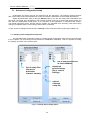
1
SV 104 USER'S MANUAL_DRAFT_______________________________________________ _ SV 104 ACOUSTIC DOSIMETER USER’S MANUAL SVANTEK Sp. z o.o. WARSAW, July 2013 1 strument Instru mentaation for Science and Industry ISI sa-nv Rue du Doyenné 3 - 1180 Brussels Tel +32 (0) 2 343 30 81 Fax 02/ 343 12 05 web : http:// www.isi-be.com mail : [email protected] SV 104 USER'S MANUAL_DRAFT_______________________________________________ _ Notice: The SV104 dosimeter contains no user serviceable parts. Opening product case invalidates the warranty. Notice: When in normal use, always fit the SA 122 windshield provided. It is suggested that the SA 122 windshield is removed whenever measurements are to be made in extremely clean environments such as food preparation or pharmaceutical manufacturing in order not to accidentally lose the windshield during the survey. Notice: Battery power indicator - To improve accuracy of remaining battery life indicator, run the dosimeter until it is fully discharged; then proceed with a full charge via the micro USB port. The procedure is recommended before first use. Repeat this procedure every few months of use to maintain more accurate current battery condition indication. Notice: On account of continuous product improvement SVANTEK reserves the right to make changes to product specifications without notice. To download the most up to date user's manual please visit our web site at www.svantek.com. This user’s manual presents the firmware revision named 1.02.01 (see the Unit Label review chapter 4.5 to check version details). This user’s manual presents some aspects of SUPERVISOR software revision named 1.0.7 (see the software start-up splash screen). The succeeding software revisions (marked with the higher numbers) can change the view of some displays presented in the text of the manual. WEEE Notice: Do not throw the device away with the unsorted municipal waste at the end of its life. Instead, hand it in at an official collection point for recycling. By doing this you will help to preserve the environment. Trademarks Microsoft and Windows are registered trademarks of Microsoft Corporation Copyright © 2013, SVANTEK sp. z o.o. All rights reserved. No part of this publication may be reproduced or distributed in any form, or by any means, without prior written consent from SVANTEK, Warsaw, Poland Thank you for buying and using this SVANTEK product! 2 SV 104 USER'S MANUAL_DRAFT_______________________________________________ _ CONTENTS 1 INTRODUCTION 8 1.1 Sound pressure 9 1.2 Dosimetry 9 1.3 Standards 10 1.4 Applications 11 1.5 Measurement procedures 12 2 KIT COMPONENTS 13 2.1 SV 104 dosimeter short form specification 13 2.2 Accessories included 14 2.3 Accessories available 14 2.4 Instrument Software (Firmware) options available 14 3 GETTING STARTED 15 3.1 System description 15 3.2 Input output interfaces description 16 3.3 The windshield 17 3.4 The mounting clips 17 3.5 LED status indicator 18 3.6 Status bar icons 18 3.7 Manual control of the instrument 19 3.7.1 Primary key functions 20 3.7.2 Alternate key functions 21 3.7.3 Alternate combined keys function 22 3.8 Three instruments in one – ACOUSTIC PROFILE concept 23 3.9 The VIEW mode presentation concept 23 3.9.1 Running SPL view mode 23 3.9.2 Primary “ONE-RESULT” parameters view mode 24 3.9.3 RESULTS LIST view mode 24 3.9.4 OCTAVE analysis spectrum view mode 25 3.9.5 INSTRUMENT STATUS view mode 26 3.10 ALARM screen review 4 26 RUNNING AND OPERATING BASIC PROCEDURES 27 4.1 Charging 27 4.2 Before you turn the instrument on 28 4.3 Turning on/off 28 4.4 Battery check 30 4.5 Reviewing unit label 31 4.6 Measurement Setups - basic configuration 32 4.7 CALIBRATION 33 3 SV 104 USER'S MANUAL_DRAFT_______________________________________________ _ 4.8 Voice comments recording 36 4.9 Before and after measurement run 37 4.10 Starting and stopping measurement run 37 4.11 Auto-run mode information 37 4.12 Security lock 38 4.13 Mounting and positioning the SV 104 38 4.14 Reviewing measurements 39 4.15 Resetting the dosimeter 39 5 SUPERVISOR BASIC OPERATIONS 40 5.1 Installing and connecting to PC 40 5.2 Main software window 41 5.3 Instruments inventory panel 42 5.4 Advanced configuration setup 43 5.4.1 Working with configuration setup files 43 5.4.2 Profile settings tab 46 5.4.3 Measurement parameters settings tab 47 5.4.4 Time-history data logging settings tab 48 5.4.5 Display VIEW configuration tab 49 5.4.6 Octave analysis Spectrum configuration tab 50 5.4.7 General settings tab 5.4.7.1 Calibration settings panel 5.4.7.2 Statistical levels settings panel 5.4.7.3 Security settings panel 5.4.7.4 Auxiliary settings panel 50 51 51 52 53 5.4.8 Auto-Run settings (timer, pauses) tab 54 5.4.9 Recording options tab 5.4.9.1 Event and Wave recording configuration panel 56 56 5.5 Working with data files 57 5.5.1 Instrument files 57 5.5.2 Local files “Data Browser” 58 5.6 Working with sessions and reporting 59 5.6.1 Report panels 6 61 SV104 MAINTENANCE 67 6.1 General recommendations for use 67 6.2 Cleaning 67 6.3 In situ calibration 67 6.4 Periodic testing 67 6.5 Changing the microphone and windshield 68 6.6 Firmware update 68 6.7 Storing the instrument 68 6.8 Transportation and carrying 69 6.9 Troubleshooting 69 4 SV 104 USER'S MANUAL_DRAFT_______________________________________________ _ 7 SVANTEK SERVICE 70 5 SV 104 USER'S MANUAL_DRAFT_______________________________________________ _ LIST OF FIGURES FIGURE 2-1 SV 104 INSTRUMENT WITH THE MICROPHONE AND WINDSHIELD.................................................................................... 13 FIGURE 3-1 SV 104 AT A GLANCE ............................................................................................................................................. 15 FIGURE 3-2 SV 104 SIDE VIEW – MICROPHONE AND MICRO USB CONNECTOR .................................................................................. 16 FIGURE 3-3 SV 104 BACK VIEW - CHARGING AND INFRARED PORT (RESERVED FOR FUTURE USE) ........................................................... 16 FIGURE 3-4 SA 122 WINDSHIELD ............................................................................................................................................. 17 FIGURE 3-5 SV 104 STANDARD MOUNTING CLIPS ........................................................................................................................ 17 FIGURE 3-6 SV 104 DISPLAY ICONS DESCRIPTION ........................................................................................................................ 18 FIGURE 3-7 CONTROL KEYPAD ON THE FRONT PANEL – PRIMARY KEY FUNCTIONS ............................................................................... 20 FIGURE 3-8 CONTROL KEYPAD ON THE FRONT PANEL – ALTERNATE KEY FUNCTIONS ............................................................................ 21 FIGURE 3-9 CONTROL KEYPAD ON THE FRONT PANEL – ALTERNATE COMBINED KEYS FUNCTION ............................................................. 22 FIGURE 3-10 RUNNING SPL VIEW MODE SCREEN......................................................................................................................... 23 FIGURE 3-11 PRIMARY PARAMETERS VIEW MODE SCREEN ............................................................................................................. 24 FIGURE 3-12 RESULTS LIST VIEW MODE SCREENS ......................................................................................................................... 24 FIGURE 3-13 OCTAVE ANALYSIS SPECTRUM GRAPH LEQ VIEW MODE SCREENS .................................................................................. 25 FIGURE 3-14 OCTAVE ANALYSIS SPECTRUM GRAPH MAX VIEW MODE SCREENS ................................................................................. 25 FIGURE 3-15 INSTRUMENT STATUS VIEW MODE SCREENS .............................................................................................................. 26 FIGURE 3-16 ALARM VIEW SCREENS.......................................................................................................................................... 26 FIGURE 4-1 POWER-OFF WARNING SCREEN ................................................................................................................................ 29 FIGURE 4-2 INSTRUMENT STATUS - BATTERY STATE...................................................................................................................... 30 FIGURE 4-3 UNIT LABEL SCREENS .............................................................................................................................................. 31 FIGURE 4-4 LOAD SETUP MENU ................................................................................................................................................ 32 FIGURE 4-5 LOAD SETUP CONFIRMATION ................................................................................................................................... 32 FIGURE 4-6 STATUS OF SETUP LOADING ..................................................................................................................................... 32 FIGURE 4-7 CALIBRATION MENU .............................................................................................................................................. 33 FIGURE 4-8 CALIBRATION - INITIAL DELAY SCREEN ........................................................................................................................ 34 FIGURE 4-9 CALIBRATION IN PROGRESS SCREEN ........................................................................................................................... 34 FIGURE 4-10 CALIBRATION CONFIRMATION SCREEN ..................................................................................................................... 34 FIGURE 4-11 CALIBRATION - MICROPHONE NOT IN TOLERANCE SCREEN ............................................................................................ 35 FIGURE 4-12 VOICE COMMENT LINKING SCREEN .......................................................................................................................... 36 FIGURE 4-13 VOICE COMMENT RECORDING COMMAND SCREEN ..................................................................................................... 36 FIGURE 4-14 VOICE COMMENT RECORDING IN PROGRESS SCREENS ................................................................................................. 36 FIGURE 4-15 VOICE COMMENT RECORD CONFIRMATION SCREEN .................................................................................................... 36 FIGURE 4-16 AUTO-RUN MODE – TIMER AND PROGRAMMABLE PAUSE SCREEN ................................................................................. 37 FIGURE 4-17 UNLOCKING THE UNIT SEQUENCE SCREENS ............................................................................................................... 38 FIGURE 4-18 SV 104 POSITIONING .......................................................................................................................................... 38 FIGURE 5-1 SUPERVISOR SPLASH SCREEN.................................................................................................................................... 40 FIGURE 5-2 SUPERVISOR MAIN WINDOW ................................................................................................................................... 41 FIGURE 5-3 INVENTORY PANEL AND ITS CAPABILITIES .................................................................................................................... 42 FIGURE 5-4 SETUP FILES MANAGER PANEL .................................................................................................................................. 43 FIGURE 5-5 EXPORTING THE CONFIGURATION SETUP FILE .............................................................................................................. 44 FIGURE 5-6 INSTRUMENT FILES PANEL AND CONTEXT COMMANDS................................................................................................... 45 FIGURE 5-7 DOSIMETER SETTINGS - PROFILE CONFIGURATION TAB .................................................................................................. 46 FIGURE 5-8 MEASUREMENT CONFIGURATION SETTTINGS TAB......................................................................................................... 47 FIGURE 5-9 TIME HISTORY (LOGGER) SETTINGS TAB..................................................................................................................... 48 FIGURE 5-10 DISPLAY VIEW CONFIGURATION TAB ...................................................................................................................... 49 FIGURE 5-11 SPECTRUM CONFIGURATION TAB ............................................................................................................................ 50 FIGURE 5-12 GENERAL SETTINGS TAB ........................................................................................................................................ 50 FIGURE 5-13 CALIBRATION SETTINGS PANEL ............................................................................................................................... 51 FIGURE 5-14 STATISTICAL LEVELS SETTINGS PANEL ....................................................................................................................... 51 FIGURE 5-15 KEYBOARD SECURITY SETTINGS PANEL...................................................................................................................... 52 FIGURE 5-16 AUXILIARY SETTINGS PANEL ................................................................................................................................... 53 FIGURE 5-17 AUTO-RUN CONFIGURATION TAB ............................................................................................................................ 54 FIGURE 5-18 AUDIO EVENT AND WAVE RECORDING CONFIGURATION PANELS ................................................................................... 56 FIGURE 5-19 SV 104 DOWNLOAD WINDOW .............................................................................................................................. 57 FIGURE 5-20 CHANGE INSTRUMENT WORKING DIRECTORY WINDOW ............................................................................................... 57 6 SV 104 USER'S MANUAL_DRAFT_______________________________________________ _ FIGURE 5-21 LOCAL FILES “DATA BROWSER” - WINDOW LAYOUT ................................................................................................... 58 FIGURE 5-22 SUPERVISOR MAIN SESSION WINDOW ............................................................................................................... 59 FIGURE 5-23 SESSION CONFIGURATION PANEL .......................................................................................................................... 60 FIGURE 5-24 MANAGING TEMPLATES WITH SUPERVISOR ........................................................................................................... 61 FIGURE 5-25 SUPERVISOR REPORT OPTIONS ........................................................................................................................... 61 FIGURE 5-26 HEARING PROTECTORS (HML) PANEL ..................................................................................................................... 62 FIGURE 5-27 INSTRUMENT CONFIGURATION PANEL...................................................................................................................... 62 FIGURE 5-28 LOGGER 1/1 OCTAVE PANEL ................................................................................................................................. 63 FIGURE 5-29 LOGGER 1/1 OCTAVE TSECT PANEL ....................................................................................................................... 63 FIGURE 5-30 LOGGER COMBINED PANEL .................................................................................................................................... 63 FIGURE 5-31 LOGGER RESULTS PANEL ....................................................................................................................................... 64 FIGURE 5-32 LOGGER STATISTICS PANEL .................................................................................................................................... 64 FIGURE 5-33 MARKED PERIODS TOTALS PANEL ........................................................................................................................... 65 FIGURE 5-34 NOISE EXPOSURE (ISO 9612) PANELS..................................................................................................................... 65 FIGURE 5-35 SESSION HEADER PANEL ........................................................................................................................................ 66 FIGURE 5-36 CONFIGURABLE TEXT PANEL .................................................................................................................................. 66 FIGURE 5-37 POWERFULL “WHAT IF” PANEL .............................................................................................................................. 66 LIST OF TABLES TABLE 1-1 EXAMPLE SOUND SOURCE LEVELS ................................................................................................................................. 9 TABLE 1-2 STANDARDIZATION ORGANIZATIONS’ WEBSITES............................................................................................................. 10 TABLE 3-1 LED STATUS DESCRIPTION ........................................................................................................................................ 18 7 SV 104 USER'S MANUAL_DRAFT_______________________________________________ _ 1 INTRODUCTION The SV 104 instrument is a revolutionary new approach to occupational health and safety noise monitoring offering voice comments, audio events recording and vibration shock detection functions which are new and useful concepts in an instrument of this size. It is a cable-free dosimeter and is typically attached to the user’s shoulder, close to the ear using the mounting clips supplied. This personal dosimeter has an incredibly robust 1/2" MEMS microphone (part number SV 27) enabling easy and automatic calibration using most commonly available acoustic calibrators. The class beating, high resolution, amazing colour OLED screen displays information in both text and graphical form and offers excellent visibility in dark sites as well as in full daylight conditions. This makes taking noise measurement a real pleasure. Three independent acoustic profiles allow parallel measurements with separately defined filters and RMS detector time constants. Each profile provides an extensive number of results (like Leq, Lmax, Lmin, Lpeak, L, LE,…). All required weighting filters (A, C, Z) can be calculated in parallel. For instance, it is trivial to set one profile to monitor noise parameters using the ACGIH (American Conference of Governmental Industrial Hygienists) preset, second profile set to OSHA HC (Occupational Safety and Health Administration - Hearing Conversation) preset and simultaneously monitor noise with the OSHA PEL (Occupational Safety and Health Administration – Permissible Exposure Level) settings. Using the computational power of its digital signal processor the SV 104 instrument can simultaneously measure the dosimeter results and perform real time 1/1 Octave analysis including the calculations of the statistical levels. An inbuilt tri-axial accelerometer for vibration shock detection firmly places SV 104 as both the most technically advanced and the most robust personal dosimeter out there. Advanced time history logging for each profile provides safe and complete information about measured signal in the internal large 8GB memory. The instrument is powered from internal new generation Ni-MH rechargeable batteries offering circa 1 40 hours of continuous operation. This new cell technology offers up to 1800 charge cycles in comparison to standard maximum 500 cycles. Low battery self-discharge is about 3% per month in comparison to 40% per month in standard NiMH technology. The powering and charging of the instrument from the USB interface is provided which also enables easy data exchange connection between the SV 104 and a PC without the requirement of a special docking station. The instrument works with Svantek’s specialist health and safety software package - Supervisor, and also with the full analysis package SVAN PC++. Robust and lightweight design including innovative magnetic mounted windshield enhances the exceptional features of this new generation instrument. Add to it the automatic calibration feature and one can say: “Never before has a noise dosimeter been so accomplished yet so affordable, making your measurements more accurate and reliable than ever before”. To get started quickly with the SV 104, the first part of the manual describes basic noise dosimetry information followed by a guide to setting up the dosimeter and running measurements. 1 Display off. Octave analysis off; 8 SV 104 USER'S MANUAL_DRAFT_______________________________________________ _ 1.1 Sound pressure The human ear responds to audible sound pressure levels in the range from 20 μPa (hearing threshold) to 20 Pa (pain threshold), resulting in the enormous scale 1:10,000,000. Since using such a large arithmetic scale is not practical, a logarithmic scale in decibels (dB) was introduced which is also in agreement with physiological and psychological hearing sensations. Therefore it is common that sound pressure is measured in decibels. Below there is sample information about expected sound levels for different sources. Sound source Sound level [dB] Jet aircraft, 50 m away, 140 or gunshot at close range 130 Threshold of pain 120 Threshold of discomfort 110 Chainsaw, 1 m distance 100 Disco, 1 m from speaker 70 Vacuum cleaner, distance 1 m 60 Conversational speech, 1 m 40 Quiet library 10 Rustling leaves 0 Hearing threshold Table 1-1 Example sound source levels 1.2 Dosimetry Noise is definitely a serious hazard in many workplaces. In case exposure to noise from machinery processes and equipment is not correctly eliminated or controlled, it may cause permanent hearing loss in workers. The, so called, inner ear is very fragile part of our hearing sense, which with current knowledge in medicine, cannot be truly repaired. Therefore it is of great importance to protect our senses from excessive noise. Exposure to high levels of noise may also create physical and psychological stress, reduce productivity and interfere with normal communications. This may lead to accidents and injuries by making it difficult to hear moving equipment, other workers, and warning signals. Undoubtedly hearing loss has a very significant impact on the quality of life for many workers and their families. Therefore measuring noise exposure in the workplace is fundamental part of all good hearing conservation and noise reduction programs. The aim of taking a measurement with a noise dosimeter is to evaluate the average exposure of employees to noise during a normal shift. Wherever the worker goes the noise dosimeter goes too so that it captures all of the harmful noise during the typical day. The dosimeter may be worn for the complete shift if the work pattern is so variable that it is difficult to predict exactly what will occur or it may be worn for a shorter but representative period and then the full day’s dose extrapolated from that sample. 9 SV 104 USER'S MANUAL_DRAFT_______________________________________________ _ 1.3 Standards The effects of high sound exposure on hearing have been studied for many years. As far back in 1954 AIHA (American Industrial Hygiene Association) – Rosenwinkel & Stewart – described a “new device which integrates sound energy over finite time periods.” In 1956 – von Witternand & von Gierke obtained a patent for a noise exposure meter for “indicating the total time that noise exceeded a certain predetermined levels.” Since then, measurements could be conducted over long periods of time and the instrument was worn by personnel under normal work conditions. Finally, organizations developed standards to regulate personal noise exposure. International standards are specified by health and safety regulations such as the European Union Parliament and Council Directive 2003/10/EC of February 6, 2003 on minimum health and safety requirements regarding the exposure of workers to the risks arising from physical agents (noise) or International Electrotechnical Commission IEC-61252 guidelines. The EU directive links to the ISO 9612-2009 Acoustics – Determination of occupational noise exposure – Engineering method. In the United States, the Occupational Safety and Health Administration (OSHA) 29 Code of Federal Regulations (CFR) 1910 General Industry Regulations: Standard No. 1910.95 Occupational noise exposure, the Mine Safety and Health Administration (MSHA), and the American Conference of Governmental Industrial Hygienists (ACGIH) have created slightly different regulations and limitations on tolerable noise exposure. Noise requirements are to ensure that the hazards associated with the exposure of workers to noise are eliminated or properly controlled. Organization Website address ISO http://www.iso.org IEC http://www.iec.ch OSHA http://www.osha.gov MSHA http://www.msha.gov NIOSH http://www.cdc.gov/niosh ACGIH http://www.acgih.org CCOHS http://www.ccohs.ca … Table 1-2 Standardization organizations’ websites Additionally, at present dosimeters should meet relevant accuracy and performance requirements defined by: - IEC 61252 - ANSI S1.25 10 SV 104 USER'S MANUAL_DRAFT_______________________________________________ _ Applications 1.4 The SV 104 noise dosimeter is extremely well suited to ISO, OSHA, ACGIH, MSHA, NIOSH, workplace noise measurements in noise exposure assessments. The dosimeter comes with pre-defined setups that suit different measurement requirements and offer versatile possibilities to be specifically configured by the user for special requirements if needed: - Measurement and control of the industrial noise work site assessments sites/plants/facilities survey monitoring systems hearing conservation compliance transportation noise studies personal noise verifications peak dosimeter for example in military applications One of the most desirable SV104 feature is the unique data logging function that stores significant number of noise parameters at regular intervals and superimposed random vibration shock or audio events during a run. Noise profiled results can be easily transferred to the Supervisor or SvanPC+ software packages. The noisiest times can be immediately seen in the graphical report and actions directed to the appropriate area. This makes checking for different regulatory bodies’ compliance and ensuring if hearing conservation programs are needed definitely easier than ever before. The SV 104 answers all the important questions such as WHEN? and HOW? did the noise exposure appear? The data logging measurements can be started immediately or they can be pre-programmed in advance so that measurement run can begin and end automatically at a preset start and end time without the need for any onsite supervision. Additionally the SV 104 allows for custom voice note comments to be added before or after the measurement run, and therefore this is the ideal instrument for the professional occupational hygienist to use for all noise exposure studies. 11 SV 104 USER'S MANUAL_DRAFT_______________________________________________ _ 1.5 Measurement procedures Preferably, when taking measurements, the noise dosimeter should be attached to the employee at the start of a shift and collected at the end of the whole shift. In case a shorter period is sampled then care should be taken to ensure that the result is representative of the full shift exposure. Shorter sampled periods require that the sampler has a deep and full understanding of the expected working tasks during the shift and the duration cycles of those tasks. Before performing any noise measurements, ensure that employees selected for evaluation are operating equipment or performing tasks under normal (representative) conditions, and emphasise the importance of continuing to work in their usual manner (wearing the dosimeter should not interfere with normal duties). Explain the purpose and procedures of sampling to the employee who will be wearing the dosimeter and the importance of not touching, tapping or interfering with the microphone. Instruct the employee not to remove the dosimeter unless absolutely necessary. The general procedure for taking measurements could be as follows: 1. Check that the indicated instrument battery life is at least twice the time required for the measuring period 2. Check the instrument setup mode is appropriate and change if necessary 3. Check the calibration of the instrument and adjust the settings if required 4. Secure the instrument onto the shoulder of the employee selected for sampling. Refer to the chapter with specific requirements regarding orientation of the microphone 5. Start the recording session manually if it is not programmed for an automatic timed start 6. At the end of the measurement period, stop the recording session, and remove the dosimeter from the employee 7. Recheck the dosimeter’s calibration. If the instrument is not within the calibration limits then the results are invalid (usually if a discrepancy is found between two successive checks of more than ± 0.5dB in the reference level, then the results of the measurements taken between the two checks should be considered invalid and the cause investigated and the measurement repeated). 8. Follow your organisation’s specific procedure for personal noise exposure recordings analysis 9. Ensure the report is submitted to the appropriate person 10. Distribute copies of noise exposure recordings to test participants, explain the results and ensure that their hearing protection adequately protects against the recorded noise exposure levels. 12 SV 104 USER'S MANUAL_DRAFT_______________________________________________ _ 2 KIT COMPONENTS 2.1 SV 104 dosimeter short form specification Acoustic Dosimeter conforming to international standards IEC 61252; ANSI S1.25; Class 2 Microphone, MEMS type: SV27, 1/2" housing OLED colour display with super brightness and contrast Large 8GB memory USB 2.0 high speed interface Parallel Slow, Fast, Impulse detectors for the measurements with A, C, Z filters Frequency Range 30 Hz ÷ 8 kHz Measurement range 55 dBA RMS ÷ 140.1 dBA Peak Dynamic Range 80 dB Exchange rates 2, 3, 4, 5, 6 Measurement results: Run Time, Lpeak, Lmax, Lmin, Lp, DOSE (%), D_8h, PrDOSE, Lav, Leq, LAV, LE, SEL8, E, E_8h, LEPd, PSEL, Ltm3, Ltm5, Lstat, PTC, PTP, ULT, TWA, PrTWA, Lc-a 3 independent user configurable acoustic measurement profiles Easy in use predefined setups Time-history data logging of Leq/Lav/Lmax/Lmin/Lpeak with variable 0.1 s to 1 hr logger step and separate summary results intervals with statistical levels 1/1 Octave real time analysis - 9 filters with centre frequencies 31 Hz ÷ 8 kHz, Type 2 – IEC 1260; presented as a bar graph with Leq and Lmax band levels plus overall A, C and Z broadband weightings (as option called SF 104-OCT) Audio events recording, triggered and continuous mode, 12/24 kHz sampling rate, wav format (as option called SF 104-WAV) Voice Comments records audio on demand, created before or after measurement, added to measurement file Vibration shock detector with user selectable variable threshold: 1g-15g Automatic acoustic field calibration with one touch activation before and after measurement Operational time > 40 hours (display off, octave analysis off) Extremely compact, light weight and robust case with IP65 ingress protection Figure 2-1 SV 104 instrument with the microphone and windshield 13 SV 104 USER'S MANUAL_DRAFT_______________________________________________ _ 2.2 Accessories included SV 27 - ½” MEMS microphone for SV 104 dosimeter SA 122 - windshield SC 156 - micro USB 2.0 cable CD with instruction Built-in rechargeable batteries (charger/ power supply wall adapter not included) 2.3 Accessories available SV 27 – ½” MEMS microphone for SV 104 dosimeter SA 122_3 – Windscreens for SV 104 dosimeter 3 pcs per pack SV 34 – Class 2 acoustic calibrator: 1000Hz/114dB SC 156 – micro USB 2.0 cable SA 54 – Charger/power supply for 1 x SV 104 SA 73 - Carrying case for 5 x SV 104 dosimeters and accessories (waterproof) SA 156 – USB HUB for charging and data download from 5 x SV104 dosimeters Supervisor Software for configuration, viewing and exporting data, USB drivers (MS Windows XP, Vista, Windows 7) for 32 and 64 bit operating systems available as freeware 2.4 Instrument Software (Firmware) options available SF 104 OCT 1/1 – real time 9 band 1/1 Octave analysis option SF 104 WAV – Audio events recording option Notice: The software options can be purchased in any time as only the introduction of a special code is required for their activation. 14 SV 104 USER'S MANUAL_DRAFT_______________________________________________ _ 3 GETTING STARTED 3.1 System description The following Figure 3-1 shows the SV 104 controls and ports: SV 27 microphone with SA 122 windshield LED status indicator Mounting accessories suspender clips AMBER: stop mode GREEN: measuring RED: alarm Colour display 128 x 64 pixel resolution Keypad Three control keys: SCROLL PROFILE ENTER Figure 3-1 SV 104 at a glance 15 SV 104 USER'S MANUAL_DRAFT_______________________________________________ _ 3.2 Input output interfaces description SV 104 instrument is equipped with a set of useful interfaces: microphone connector (essential for measuring) micro USB connector (charging, and data download) charging connector (reserved for future use) fast infrared port (reserved for future use) microphone mounting head micro USB connector Figure 3-2 SV 104 side view – microphone and micro USB connector charging connector infrared port Figure 3-3 SV 104 back view - charging and infrared port (reserved for future use) 16 SV 104 USER'S MANUAL_DRAFT_______________________________________________ _ 3.3 The windshield During use, it is strongly recommended that the SV104 is fitted with the supplied SA 122 windshield. To calibrate the dosimeter it is necessary to remove the windshield to gain access to the microphone. It is not necessary to remove the windshield to record the voice note comments. The SV 104 uses an innovative windshield magnetic technique to fit tightly onto the microphone housing. To remove the windshield just put more force holding the lower half of the foam and lift the windshield off the microphone housing. Once the SV 104 has been calibrated, refit the windshield by carefully placing it back over the microphone again. Figure 3-4 SA 122 windshield 3.4 The mounting clips Upon delivery, the SV 104 will be fitted with the standard mounting clips. Mounting clips can be easily changed using just hand force. Figure 3-5 SV 104 standard mounting clips 17 SV 104 USER'S MANUAL_DRAFT_______________________________________________ _ 3.5 LED status indicator There is a three-colour instrument LED status indicator on the SV 104, located to the right of the microphone mounting head and above the display. Table 3-1 explains conditions under which the specific LED colour appears. LED status indication Description GREEN flashing Indicates the dosimeter is running and has not exceeded once per second the alarm level. AMBER flashing Indicates the dosimeter is stopped and has not exceeded once per over a dozen seconds the dose alarm level. RED single isolated flashes Indicates vibration shock threshold has been detected. with a duration of nominally one second This will go off once the high vibration shock has ceased. RED flashing quickly, Indicates the alarm conditions: four times per second for instance: the dose has exceeded the alarm level. Table 3-1 LED status description 3.6 Status bar icons The upper part of the display is designed as basic status information provider. See the description below. EVENT or WAVE recording activation indicator LOGGER activation indicator MEASUREMENT RUN flashing indicator BATTERY STATUS indicator current ACOUSTIC PROFILE number incremental flashing during charging UNDER-RANGE indicator OVERLOAD indicator CURRENT TIME when in stopped mode or MEASURMENT TIME during measurement run. Figure 3-6 SV 104 display icons description 18 SV 104 USER'S MANUAL_DRAFT_______________________________________________ _ Manual control of the instrument 3.7 Although the Instrument is small, its keypad is designed to be minimal, but still highly ergonomic and easy to use providing effective operational capabilities. Thanks to that, the number of the control pushbuttons of the instrument is reduced to only three. Generally the user can operate the instrument by: 2 - change the VIEW mode with the <ENTER> key - select the required ACOUSTIC PROFILE with the <PROFILE> - and SCROLL thru the results with the <SCROLL> 3 key key Notice: To save power consumption and extend battery life SV 104 will automatically switch off the display after 30 seconds if no button on the keypad is pressed. The LED indicator will still inform the user about the current state of operation and any possible alarm conditions. Press any key, to reactivate the display. 2 3 See chapter 3.9 about VIEW modes See chapter 3.8 about “3in1” functionality (3 independent acoustic profiles) 19 SV 104 USER'S MANUAL_DRAFT_______________________________________________ _ 3.7.1 Primary key functions On the front panel of the instrument the following control push-buttons are located. See below for primary (short press) key functions description: ACOUSTIC PROFILE number and status bar RESULTS <SCROLL> key <PROFILE> key scroll down thru RESULTS change presented ACOUSTIC PROFILE, 1, 2, 3, 1, etc. <ENTER> key Change VIEW mode (see chapter 3.9) Figure 3-7 Control keypad on the front panel – primary key functions 20 SV 104 USER'S MANUAL_DRAFT_______________________________________________ _ 3.7.2 Alternate key functions Alternative long press of single key (keypad icons marked with red colour) allows quick access to special functions: - POWER ON/OFF the unit by holding down the <ENTER> key - Record the VOICE COMMENT by holding down the <PROFILE> - LOCK keypad and screen by holding down the <SCROLL> key key <SCROLL> key LOCK ON the keypad and screen <PROFILE> key VOICE COMMENT recording <ENTER> key POWER on/off Figure 3-8 Control keypad on the front panel – alternate key functions Holding down individual key for few seconds during which a countdown is displayed the SV 104 gives you time to decide if you really want to access the function that is going to be executed: Shutting down 3… 2… 1… for the <ENTER> Keyboard lock 3… 2… 1… for the <SCROLL> Voice comment 3… 2… 1… for the <PROFILE> key key key If you release the key too early, SV 104 returns to the last used VIEW mode and the selected control is not executed. 21 SV 104 USER'S MANUAL_DRAFT_______________________________________________ _ 3.7.3 Alternate combined keys function Additionally, combined short press of two keys simultaneously (keypad icons marked with white colour) allow quick access to even more functionalities. <SCROLL>&<PROFILE> START/STOP MEASUREMENT RUN <SCROLL>&<ENTER> <PROFILE>&<ENTER> Enter/Exit predefined SETUP LOADER Enter/Exit CALIBRATION Figure 3-9 Control keypad on the front panel – alternate combined keys function Notice: Extra additional keypad functionality is also available to display the instrument’s Unit Label screen showing the current firmware revision number. It is accessible by a short press of all three keys at once. 22 SV 104 USER'S MANUAL_DRAFT_______________________________________________ _ 3.8 Three instruments in one – ACOUSTIC PROFILE concept SV 104 is able to monitor and log noise by enabling up to three different parameter configuration settings, also referred to as “ACOUSTIC PROFILE”. One can set profile no 1 to run measurements using the OSHA HC (Occupational Safety and Health Administration - Hearing Conversation) parameters and at the same time set profile no 2 to monitor the noise with the OSHA PEL (Occupational Safety and Health Administration – Permissible Exposure Level) parameters while profile no 3 is set to ACGIH parameters. This is the true triple instrument in one. 3.9 The VIEW mode presentation concept Such an advanced noise dosimeter as the SV 104 offers a large amount of parameters for the operator to inspect. Therefore all information is divided in neatly a organized manner as VIEW modes for each PROFILE. The VIEW mode is a way in which the measurement parameters are presented to the operator. In other words, when you change the VIEW mode, specific measurement parameters and status information will be presented in different manner as distinct screen content. SV104 features the following VIEW modes, where most of them can be individually disabled: Running instantaneous SPL view mode ( 3.9.1) - can be disabled with PC software Primary “one-result” parameters view mode ( 3.9.2) - cannot be disabled Results list view mode ( 3.9.3) - can be disabled with PC software Octave analysis spectrum LEQ view mode ( 3.9.4) - can be disabled with PC software Octave analysis spectrum MAX view mode ( 3.9.4) - can be disabled with PC software Instrument Status view mode ( 3.9.5) - can be disabled with PC software 3.9.1 Running SPL view mode Running SPL presentation mode is used when measurement run is not actually running, that is when the instrument is in standby mode before or after a measurement. In this mode the current SPL result is calculated and displayed, but not stored in the instrument's memory. The purpose of this information is to give the user a first indication of the sound levels about to be measured. This can be useful for some measurements. The instrument behaves as a simple general purpose sound pressure level meter in this view mode. acronym for: Sound Level weighting filter: A,C,Z detector type: Fast, Slow, Impulse parameter value Figure 3-10 Running SPL view mode screen 23 SV 104 USER'S MANUAL_DRAFT_______________________________________________ _ 3.9.2 Primary “ONE-RESULT” parameters view mode The one result mode is always available in all measurement modes, and cannot be disabled. In one result mode any measurement result, selected via <SCROLL> , may be presented. The user may change the actual profile view by pressing <PROFILE> key. This view mode is useful if in low vision conditions or is suitable for operators with some visual impairment. acoustic profile number measured parameter name profile preset name acronym for: weighting filter: A,C,Z detector type: Fast, Slow, Impulse parameter value current criteria status bar: THreshold, Exchange Rate, CRiterion level Figure 3-11 Primary parameters view mode screen 3.9.3 RESULTS LIST view mode To get information about a number of results at one time it is handy to switch to the “results list” view mode. Up to three parameters at a time are accessible for the operator. acoustic profile number profile preset name configuration line THreshold, Exchange Rate, CRiterion level parameter values measured parameters name Figure 3-12 Results list view mode screens 24 SV 104 USER'S MANUAL_DRAFT_______________________________________________ _ 3.9.4 OCTAVE analysis spectrum view mode The instrument operates as a real time 1/1 octave band analyser (RTA). In addition and if enabled, 1/1 octave analysis is performed in parallel with the dose meter operations. All 1/1-octave digital pass-band filters (with 9 centre frequencies from 8 kHz down to 31.5 Hz; in base two system) are working in real-time with the broadband frequency weighting filters (Z, A or C) and the linear LEQ (LEQ) detector. This enables the user to pre-weight a spectrum with one of the selected broadband frequency curves if required for a particular application such as the provision of hearing protectors in the control of high workplace noise levels. Notice: The three overall TOTAL LEQ results are measured with the weighting filters (A, C, Z) without taking into account the settings of the level meters for profiles. The spectra are always linearly averaged. Thus, the TOTAL values from 1/1 octave band analysis can be different from those obtained for the profiles (if the LEQ Integration was set as Exponential). The results of 1/1 Octave analysis (so-called spectrum) can be examined by the user on a display in Spectrum VIEW presentation mode. 1/1 Octave spectra for all 9 centre frequencies of pass-band filters together with the 3 TOTAL overall values measured with the user selected frequency weighting filters are presented in the Spectrum mode if enabled in configuration setup. Spectrum cursor can be moved left and right with <SCROLL> current centre frequency , <PROFILE> keys respectively. weighting filter value of the spectrum at cursor position cursor current Total LEQ weighting filter Figure 3-13 Octave analysis spectrum graph LEQ view mode screens current centre frequency weighting filter value of the spectrum at cursor position cursor current Total Lmax weighting filter Figure 3-14 Octave analysis spectrum graph MAX view mode screens 25 SV 104 USER'S MANUAL_DRAFT_______________________________________________ _ 3.9.5 INSTRUMENT STATUS view mode Instrument Status view presents: the battery charge status along with estimated working time which is Left until the battery is expected to be completely drained and current configuration information Instrument status screen is moved down and up with <SCROLL> respectively. , <PROFILE> keys Battery status - time left - charge status name of the currently setup loaded profile presets’ names profile presets’ names Figure 3-15 Instrument Status view mode screens 3.10 ALARM screen review Apart from simple LED alarm indications (see chapter 3.5) there are a few alarm conditions, when ALARM presentation screens will appear. During a measurement run the SV 104 will immediately turn on the display at the time that the programmable alarm condition is exceeded. The detailed alarm state condition for each profile is presented to the user. Press any key, to confirm the information. Two alarm conditions detected in profile no 1 Alarm conditions detected in each profile PROFILE list Figure 3-16 Alarm view screens Notice: At any time when battery power is almost exhausted the “low battery” alarm screen may inform you about immediate recharging requirement. 26 SV 104 USER'S MANUAL_DRAFT_______________________________________________ _ 4 RUNNING AND OPERATING BASIC PROCEDURES 4.1 Charging SV104 dosimeter is equipped with an internal charger, so that the fixed internal batteries can be charged directly from USB port or optionally provided charger (SA 54). Ensure the SV 104 is fully charged prior to use by connecting it to a USB port or to USB charger. Ensure the power supply is connected and the supply is switched on. The SV 104 will automatically switch on during charging and display how much charge is within the instrument. The SV 104 will display ‘Fully charged’ once charging is complete. This should take approximately 2 hours from a fully discharged state. A charging time of about 30 minutes will be sufficient to perform greater than 8 hours of measurement. A fully charged instrument holds enough charge to run for approximately 40 hours. Note that once disconnected from USB power supply, the dosimeter will automatically switch off. If returned to the USB connection or put again onto the docking station the dosimeter keeps trickle charging regardless of whether or not it is fully charged. This keeps the battery performance in steady condition. If the battery is fully discharged prior to being placed on a charger, the SV 104 trickle charges for a short time prior to the fast charge cycle, this prevents damage to the batteries. The number of hours you have used your dosimeter from your last charge will impact your total charge time. For example, if the battery clock indicator displays 40 hours remaining on the battery and you wish to charge the battery, the approximate charging time is 1 hour. Notice: To charge a fully discharged battery, it would take approximately 1.5 to 2.5 hours. Note also, that instrument under charging condition is slightly warm. It is normal state for NiMH type cells and does not affect the measurement accuracy. Notice: To charge multiple dosimeters at the same time via the USB port, ensure your computer or possibly the powered USB hub such as the SA 156 or switch is capable in terms of providing enough current performance. Standard hub or switches without external power supply are not capable to charge multiple SV104 dosimeters due to insufficient current supply. Current estimation: Assume the current consumption on 0.5A level, and calculate required power supply requirement (N x 0.5A). Power wattage estimation: With nominal voltage of 5V per USB, the power supply wattage should be 2.5W per dosimeter (Nx2.5W). For example 5 dosimeters charged at once require: 2.5A/12.5W USB power supply For example 3 dosimeters charged at once require: 1.5A/7.5W USB power supply For example 1 dosimeter charged alone requires: 0.5A/2.5W USB power supply Notice: Use only high quality USB cables, such as SC 156. Many poor quality cables do not ensure low resistance of the cable, thus disabling proper charging of the internal cells. 27 SV 104 USER'S MANUAL_DRAFT_______________________________________________ _ 4.2 Before you turn the instrument on There are only a few things to remember: Make sure the microphone is properly fastened onto mounting head before turning on the instrument. When in use for a measurement run, always use the SA 122 windshield provided. Notice: Warm up time - After power on, the instrument should be warmed up for at least 60 seconds before starting measurement to allow the internal circuits to stabilise. 4.3 Turning on/off TURNING ON: To switch the power on the operator should hold the <ENTER> key for a couple of seconds. The instrument switches on and goes the self-test routine (during this time the manufacturer's logo, the name of the instrument and firmware version is displayed). Then the SV104 will run through a short start-up sequence, showing the current configuration setup loaded along with the names of all of three profiles, followed by battery state screen. After this, the instrument will enter the stopped (ready to measure) mode and enter the running instantaneous SPL mode if enabled. Notice: Warm up time - After power on, the instrument should be warmed up for at least 60 seconds before starting measurement. Notice: If you leave the instrument in stopped (ready to measure) mode, the display will be switched off after 30 seconds, and the unit will turn off after approximately 5 minutes of no keypad activity to save the batteries. Notice: SV 104 will show a warning screen if the battery capacity is below 2 hours of potential measurement time. 28 SV 104 USER'S MANUAL_DRAFT_______________________________________________ _ TURNING OFF: To shut down the unit the operator should hold the <ENTER> key for a couple of seconds during which a countdown (“Shutting down” 3… 2… 1… ) is displayed. Thus, the SV 104 gives you time to decide if you really want to turn off the instrument. If you release the key too early, the SV 104 returns to the last presented VIEW mode. If enabled in the configuration setup there may be presented an additional, double-check, warning screen. This is for the operator to be aware and convinced the unit is really to be turned off. See figure below: Figure 4-1 Power-off warning screen Notice: SV 104 will automatically shut down after 5 minutes in stopped (ready to measure) mode. Notice: If auto-run (timer) mode is active, SV 104 will automatically stop the measurement when the set time is over and then turn off. If no auto-run mode is used and specific time has not been preset, the unit will continue to measure until the battery is exhausted. Just before switch off, the measurement run will be stopped and all data until that point will be saved securely for later download to the PC. 29 SV 104 USER'S MANUAL_DRAFT_______________________________________________ _ 4.4 Battery check Observe the battery icon in the instrument’s icon status bar or press the <ENTER> key until the Instrument Status VIEW mode is presented and check the battery state. If it is too low, charge the batteries (chapter 4.1). Figure 4-2 Instrument Status - Battery state Battery status screen is moved down and up with <SCROLL> Press <ENTER> , <PROFILE> keys. to change to the next VIEW mode. Notice: Battery state of charge calculation is based on internal charge counter and should be considered only as an overall, not very precise, determined estimation. Therefore the time left could be noticeably different. Although the newest technology cells are used the slight degradation over time is inevitable thus aging requires occasionally factory based (or authorised service centre) replacement of the rechargeable battery cells. Notice: Battery power indicator - To improve accuracy of remaining battery life indicator, run the dosimeter until it is fully discharged; then proceed with a full charge via the micro USB port or docking station. The procedure is recommended before first use. Repeat this procedure every few months of use to maintain more accurate current battery condition indication. 30 SV 104 USER'S MANUAL_DRAFT_______________________________________________ _ 4.5 Reviewing unit label Unit label screen provides information about elementary dosimeter properties such as: Copyrighted manufacturer name: SVANTEK Instrument name: SV104 Unit serial number (SN): … SV 27 microphone serial number (MicSN): … Unit name: John_Smith [user programmable name] Firmware version: 1.02.1 CRC(OK): 94F6 Standards list, that dosimeter conforms to: o IEC 61252:2002 o ANSI S1.25:R2007 [meaning ANSI S1.25:1991 (R2007)] o Type 2: IEC 61672:2002 o Type 1: IEC 61260:1995 [meaning with +Am1 2001] To access Unit Label screen short press all three keys: <SCROLL> , <PROFILE> and <ENTER> at the same time. The following screen will be presented: serial number firmware version UNIT NAME user programmable standards conformity Figure 4-3 Unit label screens Unit label screen is moved with <SCROLL> , <PROFILE> To exit the Unit Label screen just short press the <ENTER> last presented VIEW mode. keys. key. Then SV 104 will return to the Notice: The personalized Unit Name can be set arbitrarily with SUPERVISOR software. 31 SV 104 USER'S MANUAL_DRAFT_______________________________________________ _ 4.6 Measurement Setups - basic configuration Press two keys <SCROLL> and <ENTER> at the same time. The “Load Setup” menu will appear with the list of loaded configuration setups to choose. Figure 4-4 Load setup menu To abandon setup selection, press again the <SCROLL> and <ENTER> Otherwise select the required configuration setup with <ENTER> at the same time. key navigating thru the list with <SCROLL> or <PROFILE> key. The following screen will appear, that will allow you to confirm you really want to load the selected setup or cancel the selection and return to configuration setup list: Figure 4-5 Load setup confirmation Press <SCROLL> key to cancel the setup loading, or <PROFILE> key to confirm loading selected setup configuration. Confirming the loading of configuration setup leads to the screen with status of the loading procedure: Figure 4-6 Status of setup loading After successfully setup loading it is possible to return back to list of predefined setups by pressing the <SCROLL> key, or go further to measurement screen by pressing the <PROFILE> 32 key. SV 104 USER'S MANUAL_DRAFT_______________________________________________ _ 4.7 CALIBRATION The SV 104 dosimeter is offered with the dedicated SV 27 MEMS microphone with ½” housing. It makes the calibration very easy by direct usage of commonly available acoustic calibrators with a ½” cavity. The instrument is factory calibrated with the supplied microphone for the standard environmental conditions. Because the microphone sensitivity is a function of the temperature, ambient pressure and humidity, the absolute calibration of the measurement channel should be performed locally. The instrument performs the acoustic calibration automatically, when the calibrator is placed over the microphone (first remove the windshield). The calibrator level is automatically detected and the calibration procedure is started. The user simply has to press <ENTER> key to confirm the calibration results. Calibration is only allowed in the stopped mode. A sound measurement cannot be in progress while the calibration is being performed. Notice: It is advised to perform an acoustic calibration of the instrument each time before and after the measurement run. A single calibration at the start of each day of use is usually sufficient for most regulations. Notice: The calibration factor is always added to the results in the Dose Meter or 1/1 Octave analysis mode. Notice: The manufacturer’s recommended factory calibration interval is every 12 months for this instrument to be confident in its continuing accuracy and compliance with the international specifications. Please contact your local SVANTEK distributor for further details. To calibrate the instrument manually the user has to enter the Calibration menu. 1. Adjust the actual calibration level of the calibrator to be used with the <SCROLL> and <PROFILE> keys Figure 4-7 Calibration menu 2. Attach the acoustic calibrator, SV 30A, SV 31, SV 34, B&K 4231 (or equivalent 114 dB / 1000 Hz) carefully yet tightly over the microphone of the instrument. The presence of the calibrator will be detected automatically Notice: It is also possible to use an electro-mechanical pistonphone, which generates the signal (ca 124 dB) or different type of acoustic calibrator dedicated for ½” microphones with an alternative output level such as 94 dB at 1 kHz. In any case, before starting the calibration measurement, the user has to set the level of the signal generated by the given calibrator (Level position), which is stated in the calibration certificate of the unit (the default expected value of the Calibration Level set by the manufacturer of SV 104 is equal to 114 dB). 33 SV 104 USER'S MANUAL_DRAFT_______________________________________________ _ 3. Switch on the calibrator and wait ca 30 seconds for the tone to stabilise before starting the calibration measurement 4. Start the calibration measurement by pressing the <ENTER> key 5. The calibration measurement time is set to 1 second with 3 seconds delay and stops until the same result is obtained 3 consecutive times. It is possible to stop the calibration measurement by pressing two keys at the same time <PROFILE> and <ENTER> . Figure 4-8 Calibration - initial delay screen 6. Delay before starting calibration measurement is counted down on the display. After the measurement, its result is presented on the display. Figure 4-9 Calibration in progress screen Notice: To quit the calibration procedure without saving the calibration factor press <PROFILE> and <ENTER> . 7. It is recommended to repeat the calibration measurement a few times. The obtained results should be almost the same (with ±0.1 dB difference). The reasons for the unstable results are as follows: the calibrator is not properly attached to the instrument there are external acoustic disturbances such as high noise levels close by the calibrator or the measurement channel (for example the microphone) is damaged Notice: During the calibration measurement, the external disturbances (acoustic noise or vibrations) should not exceed a value of 100 dB (when using a calibrator that generates a level of 114 dB). 8. Press the <ENTER> key in order to accept the measurement result. previous new calibration factor Figure 4-10 Calibration confirmation screen Notice: If a calibration factor does not meet tolerance criteria, you still can manually accept the microphone, but be aware of results see Figure 4-11. 34 SV 104 USER'S MANUAL_DRAFT_______________________________________________ _ Figure 4-11 Calibration - microphone not in tolerance screen 9. Post calibration. If enabled, the post processing is performed automatically under acceptance of calibration measurement. Notice: If it is required to perform so called post-calibration of the instrument. In case the Post Calibration is pre-programmed within configuration setup the SV 104 automatically adds the results to the previously saved files. 35 SV 104 USER'S MANUAL_DRAFT_______________________________________________ _ 4.8 Voice comments recording In order to record a comment, the user should press <PROFILE> key for a few seconds during which a countdown (“Voice comment” 3… 2… 1… ) is displayed. Thus the SV 104 gives you time to decide if you really want to record a voice comment. In case you release the key too early, SV 104 returns to the last used VIEW mode. Entering the voice comment recording usually brings up a window with a question to which logger file the voice comment is to be linked - to the previous or to the next one. NOTE: This window will be skipped if there are no previous logger files or the unit is just turned on. Figure 4-12 Voice comment linking screen After selecting an answer by pressing the <SCROLL> command window will open. or the <PROFILE> key the record Figure 4-13 Voice comment recording command screen Starting the recording by means of the <PROFILE> in progress will appear on the screen. - key flashing circle that indicates recording Figure 4-14 Voice comment recording in progress screens Further, one can continue to record a comment about the measurement and press <PROFILE> key to finish recording. The recording end will be confirmed with the screen comment "Saved O.K.". Figure 4-15 Voice comment record confirmation screen Notice: The voice comment can be recorded before or after the measurement run takes place and linked to the Previous or the Next measurement run. But be beware, that linking to the previous measurement will not be possible in case when the unit is switched off and on again or there are no previous logger files. In this case the recording screen will appear (with default linking the comment to the next logger file). 36 SV 104 USER'S MANUAL_DRAFT_______________________________________________ _ 4.9 Before and after measurement run Before starting a measurement ensure: 1 2 3 4 5 turn on the instrument (see chapter 4.3) there is sufficient battery operating life and free memory by checking the status screen (see chapter 4.4) select the required configuration setup (see chapter 4.6) the SV 104 is calibrated, because it affects the results (see chapter 4.7) the windshield is put on because it protects the microphone from industrial environment such as dust and moisture or from effects of impact (see chapter 3.3) After stopping the measurement run, make sure: 1 2 3 the calibration is still maintained (see chapter 4.7) download the data to PC for further analysis (see chapter 5) turn off the instrument (see chapter 4.3) 4.10 Starting and stopping measurement run START: To start the measurements the user has to press the <SCROLL> and <PROFILE> keys at the same time. The results of the measurement are displayed in the last used result’s display view mode. As an example one profile mode is displayed. One profile mode is always available for most Functions of the instrument. The results of the measurements can also be presented in other display modes, which can be enabled or disabled and adjusted to the user’s needs. STOP: The same combination of keys: <SCROLL> and <PROFILE> allows the user to stop the measurement run. All run results are always saved automatically, there is no need to save them manually. 4.11 Auto-run mode information Note, that when auto-run mode (timer and/or pause) is configured, there is information on the screen available for the user. There is no need to turn on the instrument manually. All the timer procedures can be easily pre-programmed with the use of the SUPERVISOR software. Figure 4-16 Auto-run mode – timer and programmable pause screen 37 SV 104 USER'S MANUAL_DRAFT_______________________________________________ _ 4.12 Security lock Please consider locking the keypad and display during the measurement to prevent the wearer or anybody else from tampering with the measurement run. The SV 104 can be set up to automatically go into locked mode when it starts (see chapter 5.4.7.3). That automatically prevents any tampering, but the unit can still be unlocked if necessary with proper sequence of key presses. Locking SV 104 unit: To lock the instrument the operator should hold the <PROFILE> key for a couple of seconds during which a countdown (“Keyboard lock” 3… 2… 1… ) is displayed and the unit gives you time to decide if you really want to activate security lock. If you release the key too early, SV 104 returns to the last presented VIEW mode. Unlocking SV 104 unit: To unlock the unit one has to press the keys in the correct sequence. The sequence is pre-programmed in the configuration setup (look the chapter 5.4.7.3). Note that in case the security sequence is configured via SUPERVISOR software, the simple hold of <PROFILE> key for a couple of seconds during which a countdown (“Keyboard unlock” 3… 2… 1… ) is displayed and the unit gives you time to decide if you really want to deactivate security lock. Figure 4-17 Unlocking the unit sequence screens 4.13 Mounting and positioning the SV 104 Unless specified by local legislation, personal noise dosimeters should always be mounted on the shoulder, circa 10 cm from the most exposed ear, with the microphone approximately a few cm above the shoulder. SV 104 shape and microphone height ensures proper instrument position. see Figure 4-18 below. Figure 4-18 SV 104 Positioning 38 SV 104 USER'S MANUAL_DRAFT_______________________________________________ _ 4.14 Reviewing measurements Most of the parameters can be inspected in real-time during either measurement run or stopped mode of operation. If the display screen is turned off just press any key (but watch notice below). The keys on the keypad of the instrument enable you to navigate thru most of the parameters. For specific information on the VIEW modes, please see chapter 3.9. Use the <SCROLL> key to move down the list through the various measurements Use the <PROFILE> key to change the ACOUSTIC PROFILE you would like to inspect Use the <ENTER> key to change the VIEW mode Notice: In most cases the keypad will be probably locked. To gain access to the results and unlock the keypad see chapter 4.12. Notice: After reviewing results remember to lock the keypad again in order to maintain the integrity of the measurement run by preventing uncontrolled access to the instrument. 4.15 Resetting the dosimeter SYSTEM RESET: (internal software reset clears any setup configuration, and brings back the default factory settings). See Appendix A for remote control commands description. HARDWARE RESET: (internal hardware reset, no user data is changed) Make sure the battery is not exhausted, and the unit is turned off. Hold down the <ENTER> for more than 15 seconds, and then release it. Turn on the instrument as usually (see chapter 4.3). key Notice: Hardware reset is only to be used in extreme situations such as an instrument hangup. Be aware, that a hardware reset: - will stop any pre-programmed auto-run modes - will stop measurement run - HARDWARE RESET works, even if the keyboard becomes locked out! 39 SV 104 USER'S MANUAL_DRAFT_______________________________________________ _ 5 SUPERVISOR BASIC OPERATIONS This chapter explains data storage, the configuration setup of the dosimeter, and how to customize the parameters via the Supervisor software. With use of micro USB cable, software, and SV104, it is easy to: 5.1 set up required configuration parameters and download these, so called SETUPS, straight to the SV 104 instrument retrieve time history data to view and analyze your noise recorded charts, graphs, with extended reporting functionality Installing and connecting to PC Insert the Supervisor software CD/DVD into your PC and run the installation program. After installation we are ready to connect the SV 104 dosimeter. Plug the USB cable into the computer Plug the opposite end of the cable (micro USB) into the dosimeter itself The SV 104 is powered and charged directly through the computer; thus, you do not need separate charger. The dosimeter screen will be switched on automatically with current charging information only Turn on the dosimeter (see chapter 4.3) - long press of the <ENTER> key Windows will install drivers for Svantek instruments if not previously installed Once switched on, run the Supervisor software. Figure 5-1 Supervisor splash screen Notice: Supervisor software enables communication with multiple dosimeters. Therefore, with the use of a USB hub such as the SA 156 it is pretty straightforward to connect all of them at the same time. Just make sure your computer system has enough power capability (see chapter 4.1 for details). 40 SV 104 USER'S MANUAL_DRAFT_______________________________________________ _ 5.2 Main software window The main screen of the SUPERVISOR is divided into few panels. Panels expose areas of interest of professional users and satisfy user’s needs to find, configure, download, review and assess stored data in a very simple but still professional way. Control panel enables you to select: Instrument control, Data browser or Session you work with Instrument filter enables SV 104 device selection, or other Health and Safety dedicated instruments Inventory panel detects all SV 104 connected devices (see chapter 5.3) Quick access file manager enables you to copy configuration setup files between computer and instrument internal memory (see chapter 5.4.1) Instrument configuration panel enables access to all measurement run configuration settings (see chapter 5.4.1 for details) control panel inventory panel instrument filter setup files manager Figure 5-2 Supervisor main window 41 Instrument configuration panel SV 104 USER'S MANUAL_DRAFT_______________________________________________ _ 5.3 Instruments inventory panel Click the SV 104 big instrument icon in the left “Instrument filter” Panel (see Figure 5-2) to get access to the devices. Inventory panel (Figure 5-3) enables you to see all currently connected, or previously connected instruments of the same type. There are a number of columns with information related to each particular instrument related to the correct allocation of instrument and calibrator calibration report details. “Settings” configure setup files and the dosimeter” “Download” download measurement data from the device small clock update icon button configurable columns right click on top menu row possible context operations right click on instrument row Figure 5-3 Inventory panel and its capabilities There are two control buttons near the Inventory Panel top menu: - Settings button enables to configure current local configuration file, that can be later uploaded to the SV 104 dosimeter; - Download button enables to navigate and download files directly from the dosimeter. Notice: To download any setup, or data file, first click the row related to the chosen dosimeter. 42 SV 104 USER'S MANUAL_DRAFT_______________________________________________ _ 5.4 Advanced configuration setup Customizing and saving set-ups are performed via the Supervisor. The following sections discuss each of the setup screens and explain how to save and send the parameters to the multiple dosimeter(s). Setting described here apply to the type SV104 model. If you are also using other instruments and have them connected, they will appear in the Inventory section panel, but no device will appear unless you first select the appropriate model picture on the left side of the application in instrument filter section. The clicked instrument picture denotes that the models are selectable from inventory panel when setup changes are applied and the “send setup to instruments” is selected. To gain access to settings window click the “Settings” button near the Inventory panel (see chapter 5.3) 5.4.1 Working with configuration setup files The idea behind the configuration setup is to download the configuration setup file from the instrument to the computer you are working on and referred as “Local files” destination. Then it is possible to modify the settings, and save with a custom name. list of setup files saved in local database download selected setup file or current Settings list of setup files that are in dosimeter internal memory upload selected setup file Figure 5-4 Setup files manager panel 43 SV 104 USER'S MANUAL_DRAFT_______________________________________________ _ For example: To download current settings file from the SV 104, modify it, save with custom name, send it back to the device, export the setup to USB flash memory, and make sure the uploaded settings are applied in the dosimeter follow the presented procedure described below: Once connected and selected in the inventory panel (Figure 5-3) SV 104 dosimeter is ready for the operation: 1. Select the “Settings” row position in left side panel named “Instrument files” (Figure 5-4) 2. Click the right arrow pictogram to download instrument “Settings” configuration setup to “Local files” right side panel (Figure 5-4) 3. Select the just copied “Settings” with a click: this will display quite a few configuration tabs on the right side so called Instrument configuration panel of the main Supervisor window (Figure 5-2) 4. Go through all the tabs to verify, or change required parameters of the measurement runs. Follow the chapters from 5.4.2 to 5.4.9 to understand and configure the instrument 5. Once configured, come back to setups file manager (Figure 5-4) and click the just edited “Settings” in “Local files” panel 6. Next click the “save” button in bottom area of the panel (Figure 5-4) 7. To change the name right click on the selected row, and choose “Rename” command, which enables you to input a custom name for the setup that has just been edited (see the figure below) 8. To export the setup file right click again on the selected row to open context menu and select the “Export” command (see the figure below). This will open standard save file window, where you can choose the USB flash memory disk, and save the configuration file to use on a different PC. Note, it is also possible to import the previously saved settings file to re-use a created setup configuration. upload selected setup file Figure 5-5 Exporting the configuration setup file 44 SV 104 USER'S MANUAL_DRAFT_______________________________________________ _ 9. Now it is time to upload the configuration back to the instrument. Just click the left arrow pictogram. 10. Once copied select the copied file in the Instrument files, and right click onto it to open context menu. Then choose “Apply” command (Figure 5-6). Alternatively you can enter the “Load Setup” menu directly in the instrument and load it as the current configuration. See chapter 4.6 for details. Figure 5-6 Instrument files panel and context commands 11. This ends the procedure. Disconnect the dosimeter and the instrument is now ready for a new measurement run using the settings you have just uploaded. Notice: During configuration there are quite a number of parameters to set. To understand detailed meaning of parameters and how the results are calculated refer to Appendix D and check the following by chapters. 45 SV 104 USER'S MANUAL_DRAFT_______________________________________________ _ 5.4.2 Profile settings tab The main settings where specific acoustic profile configuration can be set are located under “Dosimeter” tab. There are already predefined presets in each profile column. By choosing predefined configuration some obvious fields will be automatically greyed. Others must be setup by the user. There are three additional user defined presets, whose name can be changed during configuration with use of the little icon (notes with a pen) which is then enabled. Apart from alarm DOSE threshold there are three additional source of warning alarm, which can be set. See figure below. change user defined preset name change additional source of alarm Figure 5-7 Dosimeter settings - profile configuration tab (see chapter Notice: Note, that some profiles can be disabled to be seen later during measurement run 5.4.5) 46 SV 104 USER'S MANUAL_DRAFT_______________________________________________ _ 5.4.3 Measurement parameters settings tab Within the measurement tab you can choose in which mode of operation the SV 104 should work: Dosimeter, or Dosimeter with 1/1 octave analysis. Notice: Enabling octave analysis shortens battery life, so take it into consideration and double check the battery status before measurement run. Other basic parameters configuration is per figure provided below: select measurement mode of operation Figure 5-8 Measurement configuration setttings tab 47 SV 104 USER'S MANUAL_DRAFT_______________________________________________ _ 5.4.4 Time-history data logging settings tab To enable logging time-history data go to the “Time History” settings tab and switch the very first switch button on the left panel. In the left panel named “Time History Setup” there are basic configuration fields related to: how frequently do you want to log the parameters, what name the logger file should have, and if extended summary results should be saved. Notice: Summary results are saved on “Integration Period” basis (not on “Logger Step” time). See Figure 5-8 how to set “Integration Period” parameter. Right panel named “Results” is accessible only if “Logger” switch button is set to “On”. You have the ability to choose, which basic results for each acoustic profile should be logged during measurement run and saved in internal storage memory. profile number logger enable Figure 5-9 Time History (logger) settings tab 48 SV 104 USER'S MANUAL_DRAFT_______________________________________________ _ 5.4.5 Display VIEW configuration tab As mentioned in chapter 3.9 there are quite a few VIEW modes accessible on the display, when the dosimeter is performing a measurement run. In the left panel named “Modes views” you can select which VIEW mode will be present when you press the <ENTER> key on the dosimeter keypad Notice: If you do not want to use all three ACOUSTIC PROFILES it would be convenient for you to enable only one acoustic PROFILE to be displayed – just select the required one. Notice: The “ONE-RESULT” (chapter always present, and cannot be disabled. 3.9.2) is the only VIEW mode that is In the right panel named “Display Results”, you will find a list of over a dozen measurement parameters, that can be configured to be presented on the SV 104 display, when you press <SCROLL> parameter. key. See Appendix D to review acronyms for each Up to three profiles can be switched on Figure 5-10 Display VIEW configuration tab 49 SV 104 USER'S MANUAL_DRAFT_______________________________________________ _ 5.4.6 Octave analysis Spectrum configuration tab Real time 1/1 octave analysis is an additional optional feature. Therefore it has its own settings tab. Within this tab there are the following panels: named “Data”: This configures the weighting filter that is to be used with octave calculation. named “Scale”: Here the visible dynamic range of the graphical plot can be set, as well as the grid visibility enabled Figure 5-11 Spectrum configuration tab 5.4.7 General settings tab General settings tab concerns to many different usability options: See the followed by chapters to understand exactly how to configure these instrument settings. Figure 5-12 General settings tab 50 SV 104 USER'S MANUAL_DRAFT_______________________________________________ _ 5.4.7.1 Calibration settings panel Sometimes it is required to perform so called post-calibration of the instrument. The position Post Cal. enables the user to perform additional calibration after a measurement session and add the results to the file saved in the memory. In the panel below, there are three options for saving results: not to save “Off”, save in the last file “Last File” or save in the files which will be created after last calibration (“Files after last calibration”). Auto-calibration can be disabled if required for any reason. Figure 5-13 Calibration settings panel 5.4.7.2 Statistical levels settings panel In the Statistical Level panel it is possible to define ten percentile statistical levels, named from N1 to N10. The default statistical levels have the following settings: 1, 10, 20, 30, 40, 50, 60, 70, 80 and 90. All values have to be within the integer range [1, 99]. Each one value can be set independently from the others. Figure 5-14 Statistical levels settings panel 51 SV 104 USER'S MANUAL_DRAFT_______________________________________________ _ 5.4.7.3 Security settings panel The security setting enables you to protect access to the instrument when in use with a simple keypad password to prevent users from inadvertently terminating a measurement run. This feature is set through the Supervisor’s “General” settings tab. To turn on the security option: switch on “Lock During Measurement” button. Once turned on, the SV 104 will disable the keyboard every time, the measurement run is started. See the chapter 4.12 how to lock, and unlock the SV 104 instrument. If “Unlock on Key” is set to On, SV 104 will require special code to be input by pressing four keys defined in this panel in a particular sequence If “Unlock on Key” is set to Off, SV 104 can be locked/unlocked without providing Lock/Unlock sequence. Simply hold the <PROFILE> key for a couple of seconds during which a countdown (“Keyboard lock/unlock” 3… 2… 1… ) is displayed and the unit gives you time to decide if you really want to activate/deactivate the security lock. If you release the key too early, the operation will be cancelled. Figure 5-15 Keyboard security settings panel 52 SV 104 USER'S MANUAL_DRAFT_______________________________________________ _ 5.4.7.4 Auxiliary settings panel Under auxiliary settings panel it is possible to: Enable additional warning screens to be displayed under certain conditions: o “Logging disabled” it warns the operator that time history results will not be stored. o “Power off” additional confirmation just before switching off (see chapter 4.3) “Comment file name” defines the name of the Voice note comment file. “Comment Text” is also able to be entered here if required “Vibration Marker” is used on the basis of acceleration threshold setting (Off, 1g,…15g) the lower the threshold level selected then the more sensitive the dosimeter will be to possible bumps and shocks during use “Language” enables the user to change the menu language displayed on the screen of the dosimeter. The default language is English. Figure 5-16 Auxiliary settings panel 53 SV 104 USER'S MANUAL_DRAFT_______________________________________________ _ 5.4.8 Auto-Run settings (timer, pauses) tab The Timer panel enables the user to program the internal real time clock to act as a delayed start and stop timer. The instrument can be switched on by itself at the pre-selected programmed time and it can then perform the measurement run, which was used before it was last switched off. Auto-run feature is useful if you wish to pre-set the instruments to run and stop for a specific time period, such as a week long study. Enabled: Pause and Timer mode of operation Figure 5-17 Auto-run configuration tab The timer configured in right panel named “Timer” can be: switched off – “Off” switched on only once – “Single” or switched on many times on regular basis – “Regular” Multiple times with the period between two consecutive measurements set in the Repetition line. In the Simple instrument interface mode the Timer position doesn’t appear in the Measurement list. Selecting the mode of the timer function The timer can be switched off – “Off”, switched on only once – “Single”, or switched on many times regularly – “Regular” multiple times with the period between two consecutive measurements set in the “Repetitions Number” line. In the case when the timer function is active (“Single” or “Regular”) and the instrument is switched on the Time screen appears until the programmed measurement runs are finished. 54 SV 104 USER'S MANUAL_DRAFT_______________________________________________ _ Setting hour and day of the measurement’s start The “Start Time” determines the time for the measurement to start. The required hour and minute can be selected. The “Start Day” determines the date of the measurement start. The timer can be programmed up to one month ahead and during the date setting the current state of the Real Time Clock is taken into account. The required date can be selected. Make sure to check that the real time clock settings for the measurement location are correct before beginning a delayed timer measurement. Selecting the period between two consecutive measurements The “Repetitions Number” position is displayed when “Regular” mode is selected. This parameter can be programmed from 1 up to 100. The required date can be selected. There is also possibility to program two independent PAUSES in the form of Relative, or Absolute time programming. See Figure 5-17 for detailed settings in magnified area. 55 SV 104 USER'S MANUAL_DRAFT_______________________________________________ _ 5.4.9 Recording options tab Event and wave recording are mutually exclusive functions and as such you need to turn off the one option in order enable the other one. 5.4.9.1 Event and Wave recording configuration panel Audio Event and Wave Recording may be configured to measure in different “Recording Mode”: See figure below. Figure 5-18 Audio Event and Wave recording configuration panels 56 SV 104 USER'S MANUAL_DRAFT_______________________________________________ _ 5.5 Working with data files 5.5.1 Instrument files If you want to download any recorded files, whatever it is: logger, voice comment, or audio events files, you should click the “Download” button on the control area. inventory control buttons Press here to download selected files. Figure 5-19 SV 104 Download window Press the “Download” button, located in bottom area, and the previously selected run data files will be downloaded to local computer and the SUPERVISOR will enter “Data Browser” (see chapter 5.5.2) to further manage downloaded files. Run data files in the instrument can be optionally deleted after download by checking the box under the Download button. To change the working directory or scan other folders, press the “Change dir” button, and appropriate window will appear, see figure below. Figure 5-20 Change instrument working directory window 57 SV 104 USER'S MANUAL_DRAFT_______________________________________________ _ 5.5.2 Local files “Data Browser” Within the Data Browser tab you can see the list of previously downloaded files ready for further processing. Note that selected files will generate a short preview in the bottom area giving the operator an initial idea of the time history of the measurement results. All files are simply divided per specific function: In the case of a dosimeter: Noise dosimetry and Wave are relevant file groups. To further process the selected file or files, right click on selection, and choose “New session” command. This will bring you to the “Session” window (see chapter 5.6), where the reporting tool will allow you to quickly and professionally review and asses the data. Figure 5-21 Local files “Data Browser” - window layout 58 SV 104 USER'S MANUAL_DRAFT_______________________________________________ _ 5.6 Working with sessions and reporting One of the main advantages of the SUPERVISOR is its incredibly simple but professional and user customizable report creation. Once you get familiar with the power of document design you will love it and probably never come back to the old fashioned way of reporting. When the measurement data is downloaded via the download feature, the data is stored and viewable via the local file “Data Browser” window. Further work with data downloaded from dosimeter is based on, so called, SESSIONS – the most advanced charting, tables, and reporting capability in its class. Each SESSION is highly configurable and the template of a document once created (Figure 5-24) can be saved for future use with other measurement data. That gives the operator quick solutions at the fingertip. The information is divided into panels and viewable in customizable graphs and/or with selected measurement data/parameters. template manager change sound units (see Figure 5-24) report options change vibration units (see Figure 5-25) zoom font control generate report preview generate report SESSION configuration panel see detailed Figure 5-23 report detailed configuration area Figure 5-22 SUPERVISOR main SESSION window 59 SV 104 USER'S MANUAL_DRAFT_______________________________________________ _ SESSION configuration panel enables you to see the currently selected measurement data in the “Session data” sub-panel. double click to add panel to the report “Add panel” contains a list of available information sections or chunks so called panels that are available to place in the report. Just double click to add a new panel section to the report detailed configuration area. Note, that each panel can be added more than once. It is possible to change the information in each panel: for example: one panel with parameters sorted in a table layout, and the other with a graph, or a zoomed graph. “Panels” contains the list of currently added information chunks to the report detailed configuration area. Here you can change the names of the individual added panels. double click to jump to the selected panel “Reports” contains information about user generated documents saved by the software. SESSIONS can be archived, or deleted with single button click. Figure 5-23 SESSION configuration panel 60 SV 104 USER'S MANUAL_DRAFT_______________________________________________ _ Figure 5-24 Managing templates with SUPERVISOR 5.6.1 Report panels See the following panels, then configure, and generate report. Report options: With “Report options” window it is very straightforward to edit basic report information and predefined graphics, colour and style. Figure 5-25 SUPERVISOR Report Options 61 SV 104 USER'S MANUAL_DRAFT_______________________________________________ _ Figure 5-26 Hearing protectors (HML) panel Figure 5-27 Instrument configuration panel 62 SV 104 USER'S MANUAL_DRAFT_______________________________________________ _ Figure 5-28 Logger 1/1 Octave panel Figure 5-29 Logger 1/1 Octave TSect panel Figure 5-30 Logger combined panel 63 SV 104 USER'S MANUAL_DRAFT_______________________________________________ _ Figure 5-31 Logger results panel Figure 5-32 Logger Statistics panel 64 SV 104 USER'S MANUAL_DRAFT_______________________________________________ _ Figure 5-33 Marked periods Totals panel Figure 5-34 Noise exposure (ISO 9612) panels 65 SV 104 USER'S MANUAL_DRAFT_______________________________________________ _ Figure 5-35 Session header panel Figure 5-36 Configurable Text panel Figure 5-37 Powerfull “What if” panel 66 SV 104 USER'S MANUAL_DRAFT_______________________________________________ _ 6 SV104 MAINTENANCE 6.1 General recommendations for use 6.2 Use only high quality USB cables, such as SC 156. Many poor quality cables do not ensure low resistance of the cable, thus disabling proper charging of the internal cells It is not recommended to leave the instrument in direct sunlight conditions for prolonged periods of time. Extended exposure such as behind the car window may affect the performance. To improve accuracy of remaining battery life indicator, run the dosimeter until it is fully discharged; then proceed with a full charge via the micro USB port. The procedure is recommended before first use. Repeat this procedure every few months of use to maintain more accurate current battery condition indication. Cleaning Few things to remember: 6.3 Every time the SV 104 gets too dirty, clean the surface of the dosimeter with damp soft cloth. Pay special attention that the provided SA 122 windshield is clean because dirtiness can affect the measurements. Take off the windshield, shake off any dirt, and clean it with damp cloth. If necessary change the windshield to new one. The foam windshield is considered a consumable item and will need replacing if it becomes lost or its condition deteriorates too much. Packs of 3 replacement windshields are available under the part number SA 122_3. Pay special attention that the SV 27 microphone front part is clean because dirtiness can affect the measurements. Avoid the small inlet hole getting too dirty. Clean carefully with a dry and soft non-fraying cloth. In situ calibration It is advised to perform an acoustic calibration of the instrument each time before and after the measurement run. A single calibration at the start of each day of use is usually sufficient for most regulations. See 4.7 chapter for calibration details, please. 6.4 Periodic testing The manufacturer’s recommended factory calibration interval is every 12 months for SV 104 to be confident in its continuing accuracy and compliance with the international specifications. Notice: Please contact your local SVANTEK distributor for further details on traceable recalibrations that are recommended by most regulatory authorities. 67 SV 104 USER'S MANUAL_DRAFT_______________________________________________ _ 6.5 Changing the microphone and windshield To change the microphone, take off the windshield first (see chapter 3.3). Now, you need to unfasten the microphone from the mounting head. Unscrew the microphone in a counter-clockwise direction. To attach a new microphone, screw the microphone on clockwise until it fits tightly. It is critical to make sure the sensor is tightly fitted. Be gently and be aware not to break or strip the thread. Notice: Note, When the microphone is changed, the new microphone serial number should be programmed into the SV 104 internal memory. It can be easily programmed thru the freely provided SUPERVISOR software. In case the windshield is destroyed/lost by any accident, or it gets too dirty to afford the microphone the best protection then SVANTEK offers SA 122_3 three pcs per pack (windscreens for SV 104 dosimeter). 6.6 Firmware update SVANTEK is committed to continuous innovation path of development, and as such reserves the right to provide firmware enhancements based on user’s feedback. To update the instrument firmware: Unpack the provided firmware package. (provided as a suitable compressed file) Make sure the unit is turned off. Hold down the <PROFILE> key and press the <ENTER> key to turn on the unit. This ensures the unit will switch on and enter the special reprogramming BOOTLOADER mode. Then connect the USB cable. The <USB> text will now appear on the instrument display. Run the start.bat file. Successful firmware update will be indicated by relevant message. Turn off the unit. Notice: With use of SUPERVISOR software it is very easy to check if there are any new firmware releases available for download (see Figure 5-3 commands). 6.7 Storing the instrument To preserve the life of the internal batteries, it is recommended that the SV 104 instrument is turned off when it is stored. Do not store the instrument permanently connected to the USB port. It shortens battery lifecycle When the SV 104 is turned off, it still draws a small amount of battery power. Therefore it is recommended to charge the cell every few months if it is not going to be used regularly. 68 SV 104 USER'S MANUAL_DRAFT_______________________________________________ _ 6.8 Transportation and carrying For transportation or storage purpose, always use the packaging provided by the manufacturer. In a potentially dirty industrial environment it is advisable to use the carrying case provided by the manufacturer such as the SA 73 (see chapter 2.3), which ensures excellent mechanical and environmental protection and long term storage conditions. 6.9 Troubleshooting 1. Upon connection to the USB port, if automatic charging is not started: check the USB cable and power supply ratings of the source. 2. If the incorrect time or date is displayed when turning on the instrument connect the device to the computer and use Supervisor software to set the time and date (see) ensuring PC clock is set correctly 3. In case the instrument is not able to turn on ensure the unit is charged by connecting to USB or recommended charger. This ensures the battery is not exhausted. Then proceed with hardware reset (chapter 4.15) 4. In case your dosimeter does not respond proceed with turn-off/turn-on procedure (chapter4.3), and hardware reset of the instrument (chapter 4.15). 5. In case the measurement of the sound level is frozen or set to a fixed value proceed with turnoff/turn-on procedure (chapter 4.3), then with hardware reset of the instrument (chapter 4.15). 6. In case the reset does not help proceed to chapter 7. 69 SV 104 USER'S MANUAL_DRAFT_______________________________________________ _ 7 SVANTEK SERVICE Should your SVANTEK professional measurement equipment need to be returned for repair or for calibration, please contact the service office at the following number or contact via the SVANTEK’s website. Service Office: +48 (22) 51-88-320 or +48 (22) 51-88-322. Office hours are 8:00 a.m. to 4:00 p.m. Central European Time. - E-mail at [email protected] - Internet at www.svantek.com - Address: SVANTEK Sp. z o.o. Strzygłowska 81 04-872 Warszawa, Poland Notice: International customers: Contact your local authorized distributor from whom the product was purchased. You can obtain the name and contact information of your local authorized distributor from SVANTEK by using the e-mail or telephone information listed above or use our website to find nearest distributor office. 70 SV 104 USER'S MANUAL_DRAFT_______________________________________________ _ INDEX A Accessories available · 14 Accessories included · 14 Applications · 11 M Measurement procedures · 12 Measurement setups · 32 Mounting · 38 Mounting clips · 17 B Basic configuration · 32 Battery check · 30 C Calibration · 33 Charging · 27 Cleaning · 67 Control of the instrument · 19 P Periodic testing · 67 Positioning · 38 Primary parameters view mode · 24 Profile · 19, 21 R Resetting the dosimeter · 39 Results list view mode · 24 Running spl view mode · 23 D S Dosimetry · 9 E Enter · 19, 21, 49 F Scroll · 19, 21, 49 Security lock · 38 Service · 70 Software options · 14 Sound pressure · 9 Standards · 10 Starting and stopping measurement run · 37 Firmware update · 68 I Icons · 18 In situ calibration · 67 Instrument status view mode · 26 K U Unit name · 31 V Vibration marker · 53 View mode · 23 Voice comments · 36 Kit components · 13 L W Windshield · 17 Led status indicator · 18 71 strument Instru mentaation for Science and Industry ISI sa-nv Rue du Doyenné 3 - 1180 Brussels Tel +32 (0) 2 343 30 81 Fax 02/ 343 12 05 web : http:// www.isi-be.com mail : [email protected]