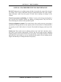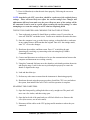
1
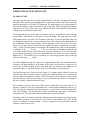
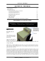
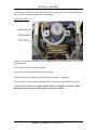
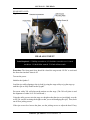
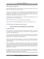
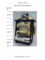
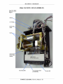
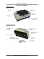
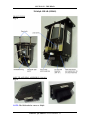
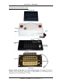
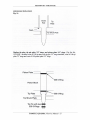
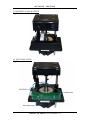
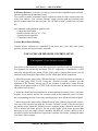
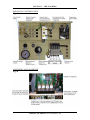
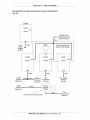
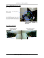
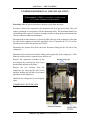
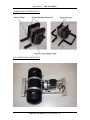
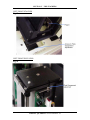
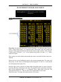
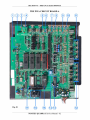
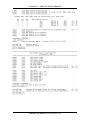
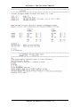
Table Of Contents
TOMTEC QUADRA 3 Service Manual - 1
TABLE OF CONTENTS
SECTION I - GENERAL INFORMATION
Warnings, Cautions, Notes, & Symbols
Specifications
Quadra 3 - Pictorials
Operational Functionality
Bar Code Installation Kit 330-10
3
4
5
7
10
SECTION II - THE HEAD
Head Removal & Installation
Head Alignment
450µL Backfill Theory of Operation
Tip Pin and O-Ring Replacement
450µL Backfill Head Pictorials
Tip Block Assembly
96SV 60µL Head Pictorials
384 60µL Head Pictorials
Piston Block
Annual Head Preventive Maintenance
12
14
15
17
19
21
22
23
24
26
SECTION III - THE STAGE
Stage Removal & Installation
Annual Stage Preventive Maintenance
28
31
SECTION IV - THE SHUTTLE
Removal & Installation of Shuttle Cover
& Bottom Covers
Installing Side Covers
Removal of Shuttle Table
Shuttle to Stage Alignment
Shuttle Calibration Text Screen
Annual Shuttle Preventative Maintenance
Shuttle Pictorials
32
35
36
40
40
42
43
SECTION V - THE STACKERS
Quadra 3 Air System
General Theory of Operation
Elevator Air Pressure Control Setup
Compressor Removal & Installation
Elevator Removal & Installation
Stacker Elevator Alignment
Stacker Escapement Test & Adjustment
Plate Present Sensor Adjustment
Annual Stacker Preventative Maintenance
45
45
47
55
57
59
62
64
66
SECTION VI - THE CPU & ELECTRONICS
Accessing The CPU
67
Changing The Quadra 3 CPU
67
Front Panel Display, Computer and Keypad
Removal & Installation
69
Top Cover Removal & Installation
72
Back Cover Removal & Installation
72
Q96A Board Removal & Installation
73
Q96B Board Removal & Installation
74
Factory Service Settings
75
Fuse Replacement
80
Quadra 3 Embedded Software Control
81
The PWA Circuit Board A
82
The PWA Circuit Board B
84
Quadra 3 Board A I/O Map
86
Quadra 3 Board B I/O Map
91
SECTION VII - ABOUT TOMTEC
Warranty
Return Policy
Decontamination Form
…If You Need Help
TOMTEC Worldwide Distributors
SECTION VIII – ERROR CODES
TOMTEC QUADRA 3 Service Manual - 2
94
94
95
96
97
SECTION I – GENERAL INFORMATION
SECTION I – GENERAL INFORMATION
Caution
Warnings, Cautions, Notes, and Symbols
Specifications
Quadra 3 - Pictorials
Operational Functionality
Bar Code Installation Kit 330-10
3
3
4
5
7
10
CAUTION
IF THE EQUIPMENT IS USED IN A MANNER NOT SPECIFIED BY THE
MANUFACTURER, THE PROTECTION PROVIDED BY THE EQUIPMENT
MAY BE IMPAIRED.
The Quadra 3 is designed for use with various liquids. These are primarily aqueous
solutions with a near neutral pH. As the pH of the solution moves away from neutral
various parts may be affected, depending on the length of time they are in contact. The
user has full responsibility for the selection of compatible liquids and for thoroughly
rinsing the system after use. Damage resulting from improper use of liquids and lack of
cleaning are the user’s responsibility and are not covered by TOMTEC’s warranty.
WARNINGS, CAUTIONS, NOTES AND SYMBOLS
Throughout this manual, there may be blocks of text printed in bold type within boxes or
italic type. These blocks are warnings, cautions, and notes, and they are used as follows:
WARNING: A WARNING INDICATES THE POTENTIAL FOR BODILY HARM AND
TELLS YOU HOW TO AVOID THE PROBLEM.
CAUTION: A CAUTION INDICATES EITHER POTENTIAL DAMAGE TO
HARDWARE OR LOSS OF DATA AND TELLS YOU HOW TO AVOID THE
PROBLEM.
NOTE: A NOTE indicates important information that helps you make better use of
your Quadra.
TOMTEC QUADRA 3 Service Manual - 3
SECTION I – GENERAL INFORMATION
Throughout this manual, there may be symbols within triangles, and they are used as
follows:
The lighting flash with arrowhead symbol, within an equilateral
triangle, is intended to alert the user to the presence of non-insulated
"dangerous voltage" within the product’s enclosure that may be of
sufficient magnitude to constitute a risk of electric shock.
The exclamation point within an equilateral triangle is intended to
alert the user to the presence of important operating and maintenance
(servicing) instructions in the literature accompanying the appliance.
SPECIFICATIONS
QUADRA 3
Environmental Specifications
Operating Environment
INDOOR USE ONLY
INDOOR USE ONLY
Temperature:
Humidity:
5 °C to 40°C (41 °F to 104 °F)
5%-90% (no condensation)
Temperature:
Humidity:
0 °C to 60°C (32 °F to 140 °F)
5%-90% (no condensation)
Storage environment
Physical Specifications
Dimensions
Width: 30.00 in. (762.00 mm)
Depth: 20.50 in. (520.70 mm)
Height: 32.50 in. (825.50 mm)
Shuttle Extension – each side: 9.50 in. 241.30 mm)
Weight
210 lb. (98.26 kg)
Electrical Specifications
Power Requirements
100VAC NOM @ 4.0A, 60Hz
105 -- 125VAC @ 4.0A, 60Hz
220 -- 240VAC @ 2.0A, 50Hz
NOTE: When sighting a location for the Quadra 3, be sure to include room for the
shuttle to travel freely – without striking anything in the front and both sides.
TOMTEC QUADRA 3 Service Manual - 4
SECTION I – GENERAL INFORMATION
OPERATIONAL FUNCTIONALITY
QUADRA STAGE
The stage lifts the plate nests from the Quadra shuttle to the tips. Four pins on the top of
the stage locate into the corresponding holes on the bottom of the nests. This permits the
precision necessary for 384 and 1536 operation. The stage height is set in the program. It
also has the ability to index in both the X and Y direction. This indexing allows formatting from 96 to 384 or 1536. Since it provides full motion, it also permits serial dilution
testing when used with the 450µL head.
To reformat, the stage must rise above the shuttle to clear it. It also must be below the tips
to clear them. This distance is referred to as the safe height. The stage must rise to this
safe height before it can offset. The X-motion of the stage is your left and right when you
are facing the Quadra. The Y-motion is front to back. The software will automatically set
the coordinates for the required offset for the quadrants of the 384 or the 1536 plate.
However, you may wish to modify these for a particular plate or application. Use quadrant # 1 of the 384 well plates as an example. The mathematical center of the quadrant #
1 calculates to be _____ X and _____ Y. To move the plate to the right, causing the tips
to be closer to the left side of the well, enter a negative number for X. To have the plate
move forward, causing the tips to move toward the back wall of the well, enter a negative
number for Y. The numbers you are entering are actual stepper motor steps. Each step
will move the stage _____ inches.
For Serial Dilution testing, the stage moves approximately half way in both directions.
Assume a full plate dilution is to be made in the twelve tip direction. A single row, of
twelve tips, is loaded in Row D. The stage shifts half way forward so the single row of
tips starts at Row A, and then, indexes to the rear so that they end up in Row H.
The Quadra stage has a built in safety feature. It is spring loaded. Should it meet an
obstacle with more resistance than the spring force (approximately 10–15 pounds) the
spring collapses and operates a safety switch. The stage reverses and moves down away
from the obstacle. This prevents injury to you, if your hand is the obstacle, or damage to
the tips if a plate is inserted incorrectly error.
When loading a rack of tips on the 450µL head, considerably more force than 10–15
pounds is required. This is accomplished with a small magnet embedded in the tip jig.
After the stage has closed the tips on the tip pins, a reed switch is actuated by the presence of the magnet. This bypasses the safety switch and the stage goes to full power
loading the tips. The tip switch confirms that the tips are properly loaded.
The stage reaches its vertical position by counting steps to the number set in the program.
If it becomes jammed or loses steps for any reason it must initialize. The stage travels
down to its bottom or home position. A sensor is operated at this point that resets the
software counter back to zero.
TOMTEC QUADRA 3 Service Manual - 7
SECTION I – GENERAL INFORMATION
There is another potential error point. If for some reason, an attempt to lower the stage is
made when it is offset (indexed away from its home position), then it will not clear the
opening in the shuttle. This is recognized by the software and the stage error message is
given. The error must be corrected to proceed.
QUADRA SHUTTLE
The concept of the shuttle is what sets the Quadra apart from its competition. The shuttle
can take plates from any of the stackers and move them to and from the pipettor. On flat
bed pipettors, a separate device, such as a conveyor or robotic arm, is required. The six
stations of the shuttle add to its utility. One station can bring in the assay plate, while
another brings in the compound or test variable plate. One station may be used for tip
washing. This leaves three stations to handle the reagents for the assay. Using pipeline
pipetting complete assays may be completed in one pass.
The shuttle is driven by two stepper motors, one in the X-direction (left /right) and the
other in the Y-direction (front/back.) Both motors may operate simultaneously permitting
a quick diagonal move when required. The software counts steps between stations. Stepper motors may loose steps if overloaded. This could happen if the shuttle is obstructed.
This is a nice safety feature but not good as a control element. The Quadra shuttles’ stopping position is determined by fixed position sensors at each station. They confirm that
the shuttle is where it should be.
A certain level of precision is required for the shuttle to stop on its mark. When the stage
rises the plate nest must fall precisely onto the stage locator pins. Rather than tune the
shuttle position sensors mechanically, they are tuned with software. The sensor has a
wider area of actuation than the final mark. The shuttle calibration procedure in the
manual describes tuning the final stopping mark to its exact point. The shuttle should stop
so that the stage lifts the plate nest and drops it back cleanly with little to no sideways or
front/back motion. This will center the plate nest on the stage locator pins.
STACKERS
The Quadra stackers are pneumatically actuated by the onboard air compressor. A low air
pressure of approximately 5psi is constantly applied to hold the stacker cylinder down.
To lift the plate nest, from the shuttle into the cassette, air pressure of approximately
20psi is applied to the cylinder. This gives a smooth upward motion due to the 15psi
differential. An air pressure gauge on the inside back panel will indicate these pressure
settings. The high and low air pressure regulators are located there also.
The escapements that release the plate from the cassette are also pneumatically driven.
The force available with pneumatics provides very reliable escapement operation. There
are no springs. The force of the air cylinder both opens and closes the escapement.
As the stacker carries the plate nest into the cassette, the escapement opens releasing a
plate to the plate nest. As the plate nest is lowered, the escapement closes to catch the
TOMTEC QUADRA 3 Service Manual - 8
SECTION I – GENERAL INFORMATION
next plate. If all microplates had the same total height and flange height, then only one
setting would be required. This not being the case, the timing of the escapements must
have some adjustment to enable handling a wide variety of microplates.
This is accomplished with a sensor mounted on the stacker air cylinder. It tells the
escapement when to open and when to close. It is adjusted with a 3/32 inch Allen wrench
through a clearance hole. The hole is located on the side of each stacker top plate.
Turning the Allen wrench one full turn clockwise moves the sensor down 1/32 inch, two
turns equal 1/16 inch. Moving the sensor down will cause the escapement to stay open
longer. Turning the Allen wrench counter-clockwise provides the opposite effect.
It may be necessary to use trial and error to determine the best position. You should count
turns clockwise or counter-clockwise from your starting point to know where you are. In
general terms, if the plate to be released is still hanging in the cassette, it probably means
the escapement closed to quickly and pinched the plate before it cleared. In this case, turn
the sensor clockwise to cause it to go down, holding the escapement open longer. If two
plates were released, instead of one, then the opposite is true. Turn the adjusting screw
counter-clockwise to cause the sensor to move up.
The top sensor, mounted on the stacker cylinder PC Board, tells the logic system that the
air cylinder has completed its upward stroke. This initiates the escapement opening
sequence. After a software time delay, the stacker air cylinder up solenoid valve closes
and vents the up motion, allowing the 5psi to drive the stacker cylinder down. The flag
actuates the bottom sensor to indicate the stacker is down and the system is ready for the
next motion. If the bottom sensor is not actuated, the logic system assumes the stacker is
up and will not move the shuttle. An error signal is generated at that time.
ACCESSORIES
There are a number of accessories that are available from Tomtec to extend the value of
the Quadra in specific applications.
Custom Reservoirs
Tomtec will specially machine custom reservoirs to match your pipetting pattern. For
example, many firms leave the first row of wells open without compounds to facilitate
adding standards and controls to the pattern. Tomtec can provide a special reservoir with
specific wells joined in the first row. Using pipeline pipetting the pipettor would aspirate
the standards and controls from the first row and air in the balance of the tips. When
moving to the compound plate the pipettor will aspirate air in the empty first row and
compounds from the rest.
Stirring Reservoir
A self-contained battery operated stirring reservoir nest will sit on the shuttle. It has three
magnetic fleas to stir the contents of the reservoir.
TOMTEC QUADRA 3 Service Manual - 9
SECTION I – GENERAL INFORMATION
Constant Level Reservoir
A peristaltic pump is used to circulate fluid to a weir type reservoir. It maintains a
constant liquid level. This provides a means of controlling the depth of pipette tip
insertion when aspirating. It eliminates refilling the reservoir for long runs of plates. It
can also be used as a means of keeping particulate matter re-suspended.
Vacuum Boxes
Several types are available. Typical examples are for Solid Phase Extraction applications.
The filtrate may be captured or passed to waste. The vacuum box rests on the Quadra
shuttle thereby maintaining registration with the pipette tips.
330-10 BARCODE READER INSTALLATION KIT
PARTS INCLUDED:
(1) 025424
(1) 193-001-30
(1) 828-001-06
(4) 830-001-01
(4) 831-001-02
(1) 890-600-01
(2) 00-0632-02
(2) 10-0600-10
(2) 52D00M3-5M
BRACKET
GROMMET (CUT)
NULL – MODEL CABLE
CABLE TIES
CABLE TIE BASES
BARCODE READER
#6-32 KEP NUTS
#6 FLAT WASHERS
M3 X 5mm FHS SCREWS
INSTALLATION PROCEDURE
1) To install (890-600-01) BARCODE READER in the QUADRA 3, be certain to
turn off power and disconnect line cord. Open the front panel and locate
connector J111, a male 9-pin sub-d, on the upper left side of the main circuit
board, behind the head. (NOTE: It is not necessary to remove the pipetting head
to install the barcode reader. If you are changing heads, plan to do it at the
same time, but installation with the head installed will alleviate the need to
realign the head.)
2) To insert connector from the barcode reader, with the head installed, hold cord
behind connector with forceps, long tweezers, or wrap masking tape around cord
and a long screwdriver. Insert connector and tighten hold down screws with a six
inch, or longer, #1 blade screwdriver.
3) Attached (024524) BRACKET to barcode reader with (2) (52D00M3-05) M3 x
5mm FLAT HEAD SCREWS. Position barcode reader/bracket assembly over #6
studs on left/right side of electronics shroud, above stage.
4) Slide bracket to lowest position and install with (2) (10-0600-10) #6 FLAT
TOMTEC QUADRA 3 Service Manual - 10
SECTION I – GENERAL INFORMATION
WASHERS and (2) (00-0632-02) #6-32 KEP NUTS; Just snug to allow for
bracket adjustment.
5) Route cord back and up through cut out behind barcode reader. Place (193-00130) GROMMET (CUT) around cord and insert into cut out.
6) Coil excess cord, and use (830-001-01) CABLE TIES and (831-001-02) CABLE
TIE BASES, to hold cord to the inside of the left/right side panel. Place “LASER
RADIATION” sticker of, appropriate language, on panel in front of the barcode
reader.
7) Connect (828-001-06) NULL-MODEM CABLE to, “Barcode Out” connection on
left side panel and “Barcode in” connection, to allow the Quadra 3 to log the bar
codes. (If using an external device to monitor the bar code reads, connect the
device to the “Barcode Out” connection.)
8) Reconnect line cord, and turn on power to Quadra 3.
9) From main menu, go to: (#5) SYSTEM SETTINGS; Enter: (#1) PREFERNECES
Enter. “BCR Mode” must be set to (#1) UP; (#2) DOWN; or (#3) BOTH. For
standard setting, use (#1) UP. NOTE: If an external device is to store barcodes,
“BCR Connection” must be set to (#1) EXTERNAL. Press F1 to save and press
“STOP/ESCAPE” twice to return to main menu.
10) For logging options refer to system settings in the Operator Manual, also sample
logs can be found in system function section.
11) Close front panel, to enable the 24 volt safety mechanism. Go to (#1)
INITIALIZE; Enter. Place a nest on station 5 with you bar-coded plate facing
left/right. Go to (#4) SYSTEM FUNCTIONS; Enter; Press F2; Press (38) JOG
STAGE UP/DOWN; Enter.
12) Press the “PAGE UP” button until stage lifts nest off of shuttle. Press and hold
“TEST” button on barcode reader for 5 seconds, this turns beam on in test mode.
Press “PAGE UP” until test beam is parallel and centered on your bar code label.
The barcode reader will flash a green light next to the “OK/NG” and the signal
strength should read at least three bars (this would be a satisfactory read).
Readjust position of reader for parallel (the lowest parallel position is usually the
best), if necessary. Tighten the nuts with 11/32” wrench. Press “TEST” button
again to turn off test mode.
13) Run QA program “BAR CODE TEST”.
TOMTEC QUADRA 3 Service Manual - 11
SECTION II – THE HEAD
SECTION II – THE HEAD
Head Removal & Installation
Head Alignment
Maintenance of Heads:
• 450µL Backfill Head Theory of Operation
• Tip Pin & O-Ring Replacement
• 450µL Backfill Head, Front View
• 450µL Backfill Head, Back View
• Tip Block Assembly
• 96SV 60µL Head
• 384 60µL Head
Annual Preventive Head Maintenance By Field Service Engineer
12
14
15
17
19
20
21
22
23
26
HEAD REMOVAL & INSTALLATION
Tools Required: # 2 Phillips screwdriver, #2 flat blade screwdriver or 1/4
inch nut driver, 1/8 Inch Allen wrench, 3/16 Inch Allen wrench
TOP BACK VIEW
Fig.3
Procedure: Shut off
power.
Take off the top cover by
removing the ten Phillips
head screws.
Open the front panel by
pulling on the bottom left
to snap it open from the left side, then pulling it out straight. It will then be able to be
swung to the right.
If the head is a 450µl backfill first insure there is no water in the head, bottle or hoses.
Then, loosen the clamp holding the hose on to the fitting on the back left over the backplane and remove the hose.
Loosen the four hold down screws and pull the head forward enough so that you can
reach the two connectors on the top left of the backplane. Once these are disconnected,
lift the head up and forward, being careful not to damage the tips if they are still attached.
You may want to remove the connectors first. To do this, loosen the two forward captive
screws that secure the B Q96 control board mounting plate all the way out. Loosen the
two back ones enough to pivot the plate and then tilt the plate up in front enough to
TOMTEC QUADRA 3 Service Manual - 12
SECTION II – THE HEAD
access the two connectors. Place the head in the storage stand. Never stand the head on
the tips. Place it where the tips will not be damaged.
TOP BACK VIEW
Fig. 4
Install the desired head, holding it while putting on the two connectors, then set it in its
proper location.
If it is the backfilll head, connect the hose.
Screw in the four Allen hold down screws part way.
Align the head in accordance to the procedure in Section III, Alignment.
Secure the B Q96 control board mounting plate, if necessary, and install the top cover.
NOTE: Check connector to B Q96 board and J202 on backplane if B board is lifted.
Remember that the software will configure to the head installed.
TOMTEC QUADRA 3 Service Manual - 13
SECTION II – THE HEAD
HEAD INSTALLED
Fig. 5
HEAD ALIGNMENT
Tools Required: # 2 Phillips screwdriver, #2 flat blade screwdriver or 1/4 inch
nut driver, 1/8 Inch Allen wrench, 3/16 Inch Allen wrench
Procedure: The front panel door should be closed the stage needs 24VDC to work and
the front door interlock shuts it off.
Turn on the power.
Initialize the Quadra 3.
Load the tips while aligning to the tip load jig using the stage utility to jog the stage up
until the tips are fully loaded on the tip pins.
Put a nest with a 384 well plate on the station over the stage. (The 384 well plate is used
the alignment of either 96 or 384 well heads.)
Using the utility screen, raise the stage to a height so that the tips are just slightly over the
wells. (Be careful in setting the height so that you avoid damaging the tips.) Then, back
out all four jacking screws.
If the tips are not level across the plate, use the jacking screws to adjust the head. If any
TOMTEC QUADRA 3 Service Manual - 14
SECTION II – THE HEAD
adjustment is made with the jacking screws, be sure that all jacking screws make contact
before completing the adjustment.
Tighten the hold down bolts and confirm that the tips are still level with reference to the
stage. Loosen the hold down bolts and continue.
For a 96 SV or 450µl head, move the head laterally to align the tips the center of the
crosshairs on a 384 well plate. (The cross hairs are the plastic between four wells of a 384
well plate that correspond to a single well in a 96 well plate). For a 384 head, move the
head laterally to align the tips to the centers of the wells.
Confirm that the head will still index 96 to 384 without the tips hitting the plate. (Insure
that straight tips are used on the 450µl head.)
Tighten the hold down bolts then recheck the alignment and indexing.
Secure the B Q96 control board mounting plate, if necessary, and install the top cover.
NOTE: The software will configure to the head installed.
450µL BACKFILL HEAD THEORY OF OPERATION
BACKFILL MODE
The head works in conjunction with a reagent bottle (buffer bottle) and a compressor.
The buffer bottle will be filled with water up to the black line. Compressed air and
vacuum are used at different times.
A hose is connected to the fitting on top of the pinch tube assembly which is connected to
the reagent bottle. The reagent bottle is connected to three valves in parallel which will
supply either vacuum unregulated or regulated pressure.
Initially, when starting to use the instrument, it is necessary to prime the head assembly
to get rid of any air. This is done by forcing water down the system, first, and then up,
completely filling it.
First, the pinch tubes are opened. The pinch tube motor operates a set of gears which
turns a cam shaft. The flat part of the cam faces forward the spring loaded clamping rod
assembly will come all the way back, unclamping the pinch tubes, allowing water to flow
through them. At this point the gap on the actuator associated with the “pinch tubes open”
photo sensor is facing down.
Compressed air forces water out of the reagent bottle through the hose to a manifold in
the pinch tube assembly. From there water is forced down through 96 pinch tubes,
through the pistons, and out of the tips into a backfill pan.
When vacuum is applied the liquid is drawn out of the backfill pan through the head and
TOMTEC QUADRA 3 Service Manual - 15
SECTION II – THE HEAD
into the reagent bottle. This is done a short period of time to insuring air is not sucked
into tips. This sequence should be done until no more bubbles are visible in the hose
connection to the buffer bottle. The system, now completely filled with water, is in the
backfill mode. Since water is incompressible, this method is more accurate than air
displacement.
AIR DISPLACEMENT MODE
In this mode the pinch tubes are in the closed position. This happens when the pinch tube
motor turns the cam pushing the clamping rod assembly forward. The gap in the actuator
associated with the “pinch tubes closed” photo sensor is facing down. This is automatic
during initialization.
When aspirating the pump motor pulls the pistons up creating suction in the tips. The
motor is stepped to turn the lead screw a certain distance corresponding to a specific
amount of liquid. When dispensing the motor pushes the pistons down forcing liquid out
of the tips.
NOTE: The pinch tubes are automatically closed during initialization and must be
manually opened before shutting off power so that the pinch tubes are not permanently
damaged.
Pump initialization photo sensor – senses flag on top of the pinch tube assembly which,
during initialization sets the reference at its highest point which equates to 450µl. The
pump will reverse direction and count down to it lowest point, “0”µl.
Tip Load Light Switch – senses that tips have been loaded at the required height and
signals that the stage can be lowered.
Reed switch – senses the magnet on the tip load fixture and temporarily disables the
stage safety switch allowing the stage to exert more pressure overcoming resistance in
loading the tips to the proper position.
Photo Sensor (NC) (Pinch Tubes Closed) – conducts when the gap on the right actuator
is facing straight down.
Photo Sensor (NC) (Pinch Tubes Open) – conducts when the gap on the left actuator is
facing straight down.
TOMTEC QUADRA 3 Service Manual - 16
SECTION II – THE HEAD
TIP PIN & O-RING REPLACEMENT
(450µL BACKFILL AND NON-BACKFILL HEAD)
Tools required: # 2, #3 and #2 stubby Phillips screwdrivers,
5/32 Allen wrench, scribe or small screwdriver
Lubricants required: O-ring lubrication, Parker Super O Lube,
part number 092-001-00 and silicon spray
Kit needed: 020570-00.
Consist of 100 pieces each of:
020046-01, Tip Pin Assembly
120-008-70, 008 O-ring
120-009-70, 009 O-ring
Procedure: Remove front panel and top covers in accordance with the procedure on page
32 (“Removal & Installation of Shuttle Covers”, Fig. 23) and on 72 (“Top Cover
Removal & Installation” Fig. 70).
It will be helpful spray the pistons with silicone so that the block can be more easily
removed. Bring the pump to its apex and spray the pistons. Cycle the pump a number of
times in order to spread the lubricant.
Shut the instrument off and remove the head in accordance with procedure page 12 & 13
(“Head Removal & Installation” Fig. 3 & 4).
Remove the tip load safety reed switch from the shuck plate.
Remove four shoulder bolts and pull the shuck plate off.
Remove the four large Phillips screws on the sides of the head assembly that secure the
piston block. Pull block off of the pistons. If there is any foreign matter on the bottom of
the pistons remove it with a lint free cloth.
You may find working on the piston block easier if the head were removed. If so refer to
the procedure on page TBD. The pump initialization photo sensor bracket may be
removed to facilitate this procedure.
Place the block upside down on a flat surface and remove the eight screws that hold the
tip plate on the block. Holding it together, turn it right side up and place it in a tip fixture.
Lift the block off the tip plate exposing the 009 O-rings. With a scribe or small
screwdriver remove them and discard.
Remove and discard the 96 tip pin assemblies (tip pin with two O-rings). Clean the tip
TOMTEC QUADRA 3 Service Manual - 17
SECTION II – THE HEAD
plate and the block with paper towels. Remove any foreign matter in the block with a
pipe cleaner or Q-tip. Replace the tip pins with part number 020046-01. Check for height
uniformity in the seat. Lubricate the new 009 O-rings, part number 120-009-70 and place
them on the tip plate.
Place the block back on the tip plate and, holding it with both hands turn it upside down,
and. replace the eight screws. Tighten them in the following pattern and sequence: A, B,
C, D, then A, B, C, D, again, then E, F, G, H. Repeat this pattern until it is tight.
TIP PLATE
Fig. 6
Place unit back on the tip fixture. Remove the piston plate by removing nine screws. Note
that the center screw does not have a lock washer. Clean with paper towels. Lubricate the
008 O-rings, part number 120-008-70, and install them on the piston plate. Replace the
piston plate and tighten the screws down in a criss-cross manner.
Replace the shuck plate with the four shoulder bolts.
Install the piston block, head and covers.
Replace the tip load safety reed switch.
Replace the head in accordance with procedure page 13.
Replace lower front cover and top cover in accordance with procedure page 34 & 72
(Fig. 28 & 70).
TOMTEC QUADRA 3 Service Manual - 18
SECTION II – THE HEAD
TIP BLOCK ASSEMBLY
TOP/FRONT VIEW
Fig. 9
BACK/BOTTOM VIEW
Fig. 8
TOMTEC QUADRA 3 Service Manual - 21
SECTION II – THE HEAD
384 60µL HEAD (020869)
FRONT VIEWS
Fig. 12
96SV TIP AND SEAL ASSEMBLY (196-101)
Fig. 13
NOTE: The 384 head also comes as 200µL.
TOMTEC QUADRA 3 Service Manual - 23
SECTION II – THE HEAD
PISTON BLOCK EXPLODED VIEW
Fig. 14
Replace tip pins, tip pin plate “O” rings, and piston plate “O” rings. (Tip Pin Kit –
includes a set of 100 tip pins with tip pin “O” rings installed, a set of 100 tip plate “O”
rings and a set of 100 piston plate “O” rings.
TOMTEC QUADRA 3 Service Manual - 24
SECTION II – THE HEAD
ANNUAL PREVENTIVE HEAD MAINTENANCE BY FIELD
SERVICE ENGINEER
Refer to figures 7 – 15.
450µL BACKFILL, 96SV & 384SV AND 384, 200µL HEADS
Grease head motor lead screw. Apply lithium grease to the lead screw with a brush and
initialize head to distribute. (Lubrication Kit, 020564-00)
NOTE: The 96SV and 384 heads have nothing else specifically to PM. When it is required, the tip and seal assemblies are replaced in the field as a unit and sent to Tomtec
for refurbishment.
450µL BACKFIIL HEAD
Check pinch tube assembly for excessive wear and misalignment of components.
Remove the top cover and front panel. In Command System under Quadra, open and
close pinch tubes repeatedly. Check for good contact between the gears on the end and
between the cams and roller bearings. Look for excessive particles deposited on the frame
below the assembly.
Backfill unit and check head integrity. Check that the air pressure is set to no more
than 1.0 psi. Check each tube to insure water is flowing out when the tubes are open and
that there is no leakage when the tubes are pinched.
Lubricate pistons. Initialize the head and turn off the power when it reaches the top of
its stroke. Spray pistons with silicon based lubricant. Do not use WD40, or a similar
product, as it will displace moisture and premature breakdown of the “O” rings may
occur.
Check guide rod shuck adjustment. Initialize the instrument. Place a tip load fixture on
one of the stations. In “Utilities” shuck tips and insure that the guide rods and shuck plate
move in unison. If they don’t, check the position of the guide rods when the head is at
rest (“0 position”) after initialization. The flat on the guide rod should be flush with the
bottom of the tip plate. In order to adjust them use a 3/16 Allen wrench to loosen them on
the front of the head.
TOMTEC QUADRA 3 Service Manual - 26
SECTION III – THE STAGE
SECTION III – THE STAGE
Stage Removal & Installation
Annual Stage Preventive Maintenance By Field Service Engineer
28
31
STAGE REMOVAL AND INSTALLATION
Prior to removing the stage, follow the procedure “Removal & Installation of Shuttle
Cover and Bottom Covers” (pg. 32-34) and “Removal of Shuttle Table” (pg. 36-39).
Tools Required: 7/16 nut driver, Phillips Screwdriver
Procedure: Once all the covers have been removed and power is shut off, take off the
cable guard by removing the two screws in front.
Disconnect the cable going to J1 on the circuit board on the stage. Note that pin 1, the red
and white wire, goes down.
Remove the four hex bolts that secure the stage to its mounting plate.
Lift the stage tilting it back until the shafts on the bottom clear the mounting plate. Pull
the stage forward, sliding the shuttle frame forward simultaneously. Avoid hitting the
pipetting tips in the process.
To install the stage, reverse this procedure.
INDEXING STAGE
Fig. 18
TOMTEC QUADRA 3 Service Manual - 28
SECTION III – THE STAGE
INDEXING STAGE (020775)
Fig. 19
INDEXING STAGE (020775)
Fig. 20
TOMTEC QUADRA 3 Service Manual - 29
SECTION III – THE STAGE
L3 INDEXING STAGE W/COVER
Fig. 21
L3 TOUCH OFF STAGE
Fig. 22
TOMTEC QUADRA 3 Service Manual - 30
SECTION III – THE STAGE
ANNUAL STAGE PREVENTIVE MAINTENANCE BY FIELD
SERVICE ENGINEER
Lubrication. Lubricate lead screw with lithium grease.
Check the function of the stage safety switches. Run one of the stages up and as it is
rising push down on the top. It should try to reach its set height three times then stop and
report a “Stage Safety Error”.
Check alignment of stages to head
• With 96LV Head. On one of the stages place a tip load fixture. Move the stage up until
it reaches the two guide rods insuring they are centered in the holes on the fixture.
• With 96SV or 384 heads. Place a corresponding microplate on a nest and place it on the
stage. Raise the stage until the plate is just below the level of the tips. Insure that the tips
are centered over the wells.
With 450 Backfill Head only, check operation of tip load switch and tip load height
setting. Load a set of tips. Then push up on a single tip and if it loaded properly it should
not move up more than a millimeter. It the tip load height is was set too low then the tips
may not seal properly and if the height is too high then the stage may end up flexing the
frame.
TOMTEC QUADRA 3 Service Manual - 31
SECTION IV– THE SHUTTLE
SECTION IV- THE SHUTTLE
Removal & Installation of Shuttle Covers & Bottom Covers
Installing Side Covers
Removal of Shuttle Table
Shuttle to Stage Alignment
Annual Shuttle Preventive Maintenance By Field Service Engineer
Shuttle Pictorials
32
35
36
40
42
43
REMOVAL AND INSTALLATION OF SHUTTLE COVER
& BOTTOM COVERS
Tools required: 11/32 nut driver, #2 Phillips screwdriver, 5/64 Allen
wrench, 7/64 Allen wrench
Procedure: Shut off power to instrument.
Remove four nuts (2 on each side underneath) that secure shuttle cover to shuttle frame.
Lift the cover up and carefully remove so that the pipetting tips are not damaged.
SHUTTLE, UNDERNEATH, RIGHT SIDE
Fig. 23
TOMTEC QUADRA 3 Service Manual - 32
SECTION IV– THE SHUTTLE
ELEVATOR NEST PLATE
Fig. 24
VIEW OF SCREW LOCATIONS FOR SIDE COVER
(TYPE I COVER SHOWN)
Fig. 25
Remove the left side cover by unscrewing the two screws that are located over the
elevator positions. Loosen, but do not remove, the two thumb screws that are on the
bottom with your fingers. Remove nest plate by removing the adjustment screw and
Phillips screw from elevator plates in the front and rear. Also remove the cover screw
under the elevator nest plate. The cover is now free to pull off.
TYPE II COVER
Fig. 26
TOMTEC QUADRA 3 Service Manual - 33
SECTION IV– THE SHUTTLE
FLOPPY DISK DRIVE
Fig. 27
To remove the right cover, unscrew the air regulator adjustment then remove the screws
in the same relative positions as the left side. With the floppy disk drive cables attached,
carefully pull the side cover free and remove the two cables. Since the gray ribbon cable
can be inserted either way, note the side of the cable that is red faces inboard on the drive.
LOWER FRONT COVER
Fig. 28
To remove the lower front cover remove the thumb screw underneath and the pull the
front cover off.
NOTE: The spring loaded washers on each side do not require any adjustment.
TOMTEC QUADRA 3 Service Manual - 34
SECTION IV– THE SHUTTLE
LOWER FRONT AREA (FRONT COVER REMOVED)
Fig. 29
INSTALLING SIDE COVERS
ELEVATOR
Fig. 30
Prior to installing the covers, on each elevator,
center the nut plate in order locate the nut with
the screw once the cover is on.
Fig. 29
Replace the plate nest. Tighten the Phillips screw to secure it to the cylinder. With no air
pressure (power still off), lift the elevator and from underneath push up on the anti
rotation device. Insure that the anti rotation device does not rub up against the elevator
body and that the flags do not touch the light switches. Tighten the nest plate adjustment
screw. Turn on power and test lift the elevator with a plate on it to insure smooth
operation. Repeat adjustment procedure if necessary.
TOMTEC QUADRA 3 Service Manual - 35
SECTION IV– THE SHUTTLE
REMOVAL OF SHUTTLE TABLE
Tools required: 5/32 Allen wrench, # 2 Phillips screwdriver
Procedure: Follow the procedure “Removal & Installation of Shuttle Cover and
Bottom Covers” (pg. 32-34)
Remove the back cover in accordance to the procedure 72 (Fig. 71).
Remove two screws in the upper right and left corners of the pneumatic panel.
PNEUMATIC PANEL, REMOVING SCREWS
Fig. 31
PNEUMATIC PANEL, TILTED FORWARD
Fig. 32
Follow the cable to the Y motor on the shuttle base on the left side of the instrument.
TOMTEC QUADRA 3 Service Manual - 36
SECTION IV– THE SHUTTLE
LOWER BACKPLANE, Y MOTOR, CONNECTORS REMOVED
Fig. 33
Remove the four Allen bolts on both sides of the frame that secure the shuttle base to it.
It would be helpful to have a second person feeding the cable as the shuttle is removed.
SHUTTLE TABLE, FORWARD
Fig. 34
Lift and pull the shuttle forward, insuring that the side plate on the shuttle stays vertical.
TOMTEC QUADRA 3 Service Manual - 37
SECTION IV– THE SHUTTLE
SHUTTLE TABLE, LIFTED
Fig. 35
SHUTTLE TABLE, LIFTED
Fig. 36
TOMTEC QUADRA 3 Service Manual - 38
SECTION IV– THE SHUTTLE
SHUTTLE REMOVED, SHOWING CABLES
Fig. 37
Reverse this procedure to install.
TOMTEC QUADRA 3 Service Manual - 39
SECTION IV– THE SHUTTLE
SHUTTLE TO STAGE ALIGNMENT
Each of the six stations on the shuttle must have the same relationship with the stage in
the X and Y directions. In each station this is tested by raising and lowering the stage
with a nest on it and verifying that it rest squarely on the shuttle. The stacker elevators are
checked in the same way. If the nest does not seat squarely on the station the shuttle
needs to be calibrated with the stage as a reference. Changes can be made to the number
of steps in the shuttle movement under “SHUTTLE CALIBRATION” in the Factory
Setting screen but it is better to use [F2] Shuttle Calibration.
SHUTTLE CALIBRATION TEXT SCREEN
Fig. 38
SHUTTLE CALIBRATION TEXT SCREEN:
Stackers: Pressing the buttons on the front panel with numbers 7, 8, 9, and 0 will raise
the corresponding stacker elevator when pressed the first time and lower it when pressed
again.
Shuttle: Pressing numbers 1 to 6 will cause the shuttle to move so that the corresponding
station is over the stage.
Stage: Pressing “Page Up” will cause the stage to rise, and pressing “Page Down” will
cause it to lower.
TOMTEC QUADRA 3 Service Manual - 40
SECTION IV– THE SHUTTLE
Calibrate Shuttle: pressing the right, left, up, or down arrows in the front panel will
cause the shuttle to move in the corresponding direction the number of steps selected
using F3.
Pressing the right arrow will cause the shuttle to move right (+ X direction). Pressing the
left arrow will cause the shuttle to move left (- X direction). Pressing the up arrow will
cause the shuttle to move away from the operator (+Y direction) Pressing down arrow
will cause the shuttle toward the operator (-Y direction).
[F1] SET: Saves any changes made in the Shuttle Calibration text screen and closes it.
[F2] NEXT POSITION: Moves the shuttle so that the next station is positioned over the
stage and repeats the movement 2 and 5 from the opposite direction. See the sequence
under “Procedure Using F2” below.
[F3] ____ STEP PER ADJ: The number of steps per depression of the arrow keys can
be set to 1, 5 or 10.
[ESC] CANCEL: Closes the screen without saving changes.
PROCEDURE USING F2:
In order to align the shuttle to the stage place a plate nest on all six shuttle stations. In the
“Factory Settings” display, Press F2 which will open the Shuttle Calibration text screen
and initialize the shuttle leaving it with station 1 over the stage.
Pressing F2 after each movement will continue to move each shuttle station over the
stage in the following sequence:
Moves left to station 2
Moves left and then right, back to station 2
Moves left to station 3
Moves backward to station 4
Moves right to station 5
Moves right and then left, back to station 5
Moves right to station 6
Moves forward and returns to station 1. This sequence will continue as long as F2 is
pressed after each shuttle movement.
NOTE: If a station is selected out of sequence by pressing numbers one to six, pressing
F2 again will continue the sequence where it was left off.
Using F2, move from one position to the next. After each movement raise and lower the
stage. The nest should lift off the shuttle table with the locator pins on the stage going
smoothly into the hole on the nest. The nest should seat back on the shuttle with the
locator pins going into the holes without hitting the shoulder. If the nest is not flat on the
TOMTEC QUADRA 3 Service Manual - 41
SECTION IV– THE SHUTTLE
shuttle, or if the pins hang up on the shoulder before seating, then adjustment is
necessary.
Use the arrow keys to adjust the shuttle. Raise and lower the stage to check it after each
adjustment. In each station position over the stage, raise and lower each stacker elevator
that the shuttle is over and check the smoothness of raising and lowering he nest in the
same manner.
Press F2 and repeat this procedure for the next position. Continue testing and adjusting
all six positions of the shuttle in the same manner until all six positions are satisfactory.
Front to back adjustments will affect all stations in that row. (I.e. adjusting station 1 back
will also adjust stations 2 and 3 back.) Left to right adjustments affects both stations in
the same column. (I.e. adjusting station 1 left will also cause station 6 to shift left.) Other
column pairs are 2 & 5 and 3 & 4.
ANNUAL SHUTTLE PREVENTIVE MAINTENANCE ON THE
QUADRA 3 BY FIELD SERVICE ENGINEER
Clean guide rods with alcohol based solvent. Refer to Fig. 38 & 41. This is strictly a
cleaning of possible spilled liquids. Lubrication may foul the linear bearings. Remove the
“X” direction shuttle table and wipe the rods clean. You MUST NOT remove the guide
rods from the bearing blocks unless you suspect that a foreign substance has fouled the
blocks.
Exercise shuttle and check for binding or excessive play. Develop a program to move
the X and Y tables table to the extent of their range, left and right, forward and backward.
Insure that the movement is smooth and steady while listening for irregularities.
Check shuttle to stage alignment (raise and lower). With a nest or tip load fixture on
one of the stages raise and lower it in each shuttle station. It should move smoothly in and
out of the guide holes. Some compromise between stations may be necessary. Use your
own judgment to determine what is acceptable.
TOMTEC QUADRA 3 Service Manual - 42
SECTION V – THE STACKERS
SECTION V – THE STACKERS
Quadra 3 Air System,
Elevator Air Pressure Control Setup
Compressor Removal and Install
Elevator Removal and Install
Stacker Elevator Alignment
Stacker Escapement Test and Adjustment
Plate Present Sensor Adjustment
Annual Stacker Preventative Maintenance
45
47
55
57
59
62
64
66
QUADRA 3 AIR SYSTEM
NOTE: In addition to the following information, please refer to the Q3 PNEUMATIC
DIAGRAM in the envelope at the back of this manual.
The air system consists of these main elements:
• Combination compressor/vacuum pump
• Three pressure regulators; high, low, and precision
• Four solenoid valves
• Pressure gauge
GENERAL THEORY OF OPERATION
The compressor supplies its output to the systems used for reagent time dispense backfill,
“dry tubes”, as well as the plate elevator system. Also, the cassette-based plate handling
is pneumatically controlled. Pressure can be monitored at four points on the pneumatic
control panel.
Solenoid valves are used on the inlet (vacuum) side and outlet (pressure) side of the
pump to allow one or the other function to be performed with its opposite function open
to the atmosphere. A muffler is mounted on the normally open side of SV102, the valve
that provides vacuum doing backfill. During other modes two other solenoids are used to
select different pressures.
PLATE ELEVATOR SYSTEM
The plate elevator system uses a 2-125 PSI regulator set to approximately 25 PSI to raise
the elevators and a 0-10 PSI regulator set to approximately 5-8 PSI to provide air spring
to return the system to its rest position. This “return” pressure is presented to the
cylinders at all times. Each of the four elevators has a solenoid valve to control the highpressure actuation. The exhaust side of these valves outputs to the atmosphere. In humid
conditions some condensation dripping should be expected at these points.
Backfill System
TOMTEC QUADRA 3 Service Manual - 45
SECTION V – THE STACKERS
When SV102 is energized the vacuum side of the pump is connected from the pump
through a manifold directly to the reagent bottle for the purpose of suctioning reagent
(aspirating) from a shuttle mounted reservoir in the backfill mode. At the same time
SV104 is energized allowing the pressure from the compressor to be vented to the
atmosphere via the NC port. The other solenoid valves are at rest at this time. SV102 and
SV104 are at rest when not in backfill during which time pressure is allowed to pass
through SV104 to the reservoir and vacuum is vented through the muffler via SV102.
Time Dispense System
The reagent time dispense system uses a precision 0-5 PSI regulator set to 5 PSI. This
regulator is located on the lower right side of the instrument. When SV103 is energized
5PSI is transferred through it to the reagent bottle. The other three solenoid valves are off
at this time. SV103 is off all other times.
Dry Tubes
In this function SV101, which is connected to the reservoir, is energized allowing
unregulated pressure (no more than 32-36 PSI) to enter the bottle. The other three
solenoid valves are off at this time. SV101 is off position all others times.
SOLENOID VALVE CONDITIONS
Mode
SV1O1
SV1O2
Backfill
Dry Tubes
Time
Dispense
SV1O3
SV104
off
on
off
on
on
off
off
off
off
off
on
off
Pneumatic Control Panel
The control panel is provided for set-up and troubleshooting. A single pressure gauge can
be connected to key points of the system through a patch-cord arrangement of four shutoff type disconnects. The following ports can be monitored:
1) Compressor Pressure – monitors pressure at manifold
2) Bottle Pressure – monitors pressure going to reagent bottle and is adjustable by the
precision regulator on the lower right side of the instrument.
3) Return Pressure – monitors “elevator down” pressure and is adjustable by the low
pressure regulator on the pneumatic panel with a flat blade screwdriver.
TOMTEC QUADRA 3 Service Manual - 46
SECTION V – THE STACKERS
4) Elevator Pressure – monitors “elevator up” pressure and is adjustable by the elevator
pressure regulator on the pneumatic panel.
Two “stacker override” momentary toggle switches are used to release a plate in any one
of the four stackers. Two “elevator override” toggle switches with two positions each
provide manual control for four elevators. The “tip load override” switches are for future
use.
Also mounted on the pneumatic panel are the:
• Compressor fuse holder
• Stacker cylinder valves, CV1 – CV4
• System pressure manifold
• Compressor control relay
Cassette-Based Plate Handling
Cassette release solenoids are controlled by the three way valves that send system
pressure to return and release stacker solenoids.
ELEVATOR AIR PRESSURE CONTROL SETUP
Tool required: 1/4 inch flat blade screwdriver.
The section of the pneumatic system that controls the operation of the four elevators has
two regulators for elevator up and down. The AC compressor is controlled by a solid
state relay energized by the system 24VDC. If the panel is opened while power is on, an
interlock on the front panel shuts off the 24VDC which shuts off the compressor.
1. Move the pressure gauge to the “Elevator Pressure” port. Pull the knob out and turn it
CW so that gauge reads 25 PSI. Using the “Elevator Override” switches, test the
operation of the elevators moving any of the elevators up and down. Insure that the
reading on the gauge returns to 25 PSI. If the elevator stays up when the switch is in the
off position, refer to step 3.
2. Insure the shuttle has been initialized or at least positioned correctly. Place a full stack
of plates in one stacker, and use the override switch on the pneumatic panel to activate
the corresponding elevator. If necessary turn the pressure up to lift the full stack of plates.
3. Move the pressure gauge to the “Return Pressure” port. With no plates in the cassette,
raise one of the elevators up using the “Elevator Override” switch. If the elevator stays
up, starting at 5psi, adjust the “Return Pressure” regulator (using a flat blade screwdriver)
CW to increase the down pressure. Do not go any higher on the down pressure than
necessary to lower the empty elevator smoothly. Recheck the elevator's ability to lift a
full stack of plates and readjust the up pressure regulator if necessary, pushing the knob
in to lock it when complete.
TOMTEC QUADRA 3 Service Manual - 47
SECTION V – THE STACKERS
PNEUMATIC CONTROL PANEL
Fig. 43
SOLENOID VALVE MANIFOLD
Fig. 44
TOMTEC QUADRA 3 Service Manual - 48
SECTION V – THE STACKERS
ELEVATOR MANIFOLD (LEFT SIDE)
Fig. 50
STACKER MANIFOLDS
Fig. 51
TOMTEC QUADRA 3 Service Manual - 54
SECTION V – THE STACKERS
COMPRESSOR REMOVAL AND INSTALLATION
Tools required: #2 Phillips’ screwdriver, socket set with
11/32 socket, minimum 8 inch extension.
Procedure: Shut off power and remove the power plug from the outlet.
In order to remove the compressor, the instrument has to be put on its back. This will
require a minimum of two people to lift the instrument safely. The instrument should rest
on something (like a piece of wood for example) in order to keep the ground terminal and
various connectors from being damaged.
Disconnect the in-line connector of electrical cable at the top of the compressor. Note that
the cable on the compressor has black and white wires if it operates on 115VAC or blue
and brown wires if the unit operates on 230VAC.
Disconnect the pressure hose from the quick disconnect fitting on the left side of the
compressor.
Disconnect the vacuum hose from the fitting on the right side of the compressor. A flat
blade screwdriver may be required to pry the hose off.
Remove the compressor mounted on the
two brackets by removing the four screws
that hold the brackets to the frame.
Remove the two brackets from the
compressor by removing the four screws
and nuts holding the brackets to the shock
absorbers on the compressor.
Install the new compressor by reversing the
order.
COMPRESSOR, BOTTOM VIEW
Fig. 52
TOMTEC QUADRA 3 Service Manual - 55
SECTION V – THE STACKERS
COMPRESSOR WITH BRACKETS
Fig. 53
24V COMPRESSOR AND BOTTLE
Fig. 54
TOMTEC QUADRA 3 Service Manual - 56
SECTION V – THE STACKERS
ELEVATOR REMOVAL AND INSTALLATION
Tools required: 3/32 Allen wrench, #2 flat blade
screwdriver
Procedure: Shut off power.
Move shuttle table to toward the opposite side that you are working on.
Remove the side covers in accordance with the procedure on page 33 (Fig. 25).
NOTE: The elevators on the right side of the instrument are orientated the opposite
way that the left side is orientated. On the left side the circuit board faces forward. On
the right side it faces the back of the instrument. This is for proper orientation of the
side cover screw holes on the elevator top plate.
Remove the hose on the top of the valve located on the on the circuit board side while
holding the valve. A flat blade screwdriver may be needed to pry it off.
Remove the hose on the opposite side on the upper part of the cylinder.
Remove the cable attached to J1. Note that the connector is not keyed so care must be
used when reinstalling it.
Remove the four Allen bolts that secure the elevator to the frame. The Allen bolts are
screwed in to a plate underneath the frame. (There are two screws per plate).
TOMTEC QUADRA 3 Service Manual - 57
SECTION V – THE STACKERS
STACKER ELEVATOR ALIGNMENT
Tools required: 3/32 Allen wrench
NOTE: This procedure may be used for any one of the four stacker elevators.
Procedure: Turn off power.
Remove the left or right side cover according to the procedure on page 33 Fig. 25.
Loosen the four hold down bolts on the bottom of the elevator.
Replace the nest plate of the elevator, and ensure that the nest plate and mounting plate
are flush. The plate escapement adjustment screw will be centered in the alignment hole.
Tighten both screws. Insure that the elevator moves up and down without binding. If the
anti-rotation device rubs the elevator body, loosen the hex screw and realign the antirotation device. In order to not change the timing, place .090 spacers under the top plate
to simulate the side cover. Confirm that sheet metal flags pass through the center of all
three light switches and do not contact the light switch housing.
Turn on power and initialize the Quadra 3.
From the main menu, select “System Settings”, (4) and press enter. Select “Shuttle/
Stacker/ Stage/Pump Utility”, (4) and press enter. Press 5 to move the shuttle so that
station 5 is over the stage.
Place a plate nest on the station over the elevator. In the utility screen, use the infeed or
outfeed to raise and lower the nest. When raising the nest, it should go smoothly into the
stacker cassette. When lowered, the locating pins on the nest should seat squarely and
smoothly into the locating holes on the shuttle station. If this does not happen, adjust the
elevator laterally to compensate for the error. For example, if the locating pin on nest
hangs up slightly on the forward part of the hole in the shuttle, then move the elevator
slightly toward the back. Test again after each adjustment. It may take a number of
iterations to get it satisfactory.
Tighten the four hold down bolts.
Raise and lower the nest again to verify smooth operation.
Shut off power and replace the covers.
TOMTEC QUADRA 3 Service Manual - 59
SECTION V – THE STACKERS
STACKER ESCAPEMENT TEST AND ADJUSTMENT
Tools required: 3/32 Allen wrench
Procedure: Use two of each of the following plates in the stacker to be tested with no
special order of placement:
Standard 96 or 384
Whatman deepwell
PCR plate, ABI 384
Nunc 1536
96 well microtube rack
In the main menu, select “System Functions”, (4), and press enter. Select “Shuttle/Stacker
Stage/Pump Utility”, (4), and press enter.
Using the utilities screen, infeed plates verifying that that stacker is releasing one plate at
a time. Remove the plates from the nest by hand. You may want to outfeed them also but
the adjustment has to be made based on the performance of the flippers on infeed.
The adjustment for changing the amount of time the flippers are open, allowing a plate to
drop, is located on the associated elevator and accessed through the shuttle station. On the
left side of the instrument access to the adjustment is on the front of the elevator top
plate. On the right side of the instrument, the access is on the back of the elevator top
plate.
View the “Stacker in Delay” on the factory settings screen. It should be at least 200. If it
is not, call Tomtec service.
If a plate does not drop when it’s supposed to, adjust in a CCW direction to lengthen the
time the flippers are open. If two plates drop at the same time, adjust in the clockwise
direction to shorten the time the flippers are open.
If an adjustment is made, then all of the test plates have to be run through again. The test
is not complete until all test plates are run through without any adjustment.
TOMTEC QUADRA 3 Service Manual - 62
SECTION V – THE STACKERS
LEFT FRONT STACKER
Fig. 58
LEFT FRONT ELEVATOR
Fig. 59
TOMTEC QUADRA 3 Service Manual - 63
SECTION V – THE STACKERS
PLATE PRESENT SENSOR ADJUSTMENT
Tools required: 3/32 Allen wrench, jewelers’ flat blade
screwdriver
LIGHT SWITCH STATUS
Fig. 60
Procedure: On the main menu select “System Functions”, (4), and press enter. Press F2.
Select “Light Switch Status”, (0), and press enter. Notice that in the left column, the
presence of the right front and rear and left front and rear light switches. “Plate Present”
is abbreviated “Plt Prsent”. A “0’’ (true) indicate the presence of a plate. A “1” (false)
indicates no plate.
Place stacker nest on the shuttle station under the stacker associated with the sensor to be
adjusted.
Remove the two screws holding the sensor to the cassette mounting plate. The sensor will
hang freely. On the sensor, the dark/light mode (designated “D” and “L”) switch should
be in the light position (fully CW).
Hold the light switch so that the red beam shines through the hole in center of the nest.
Turn the sensitivity adjustment to the fully CW position which is maximum sensitivity.
Back off the adjustment until a “1” is displayed. Place a black plate on the nest. The
status should switch to “0”. This may have to be repeated until it is just right.
Install the sensor. Test again and repeat procedure if necessary.
TOMTEC QUADRA 3 Service Manual - 64
SECTION V – THE STACKERS
An installed sensor, which sees a plate when one is not present, requires a decrease in
sensitivity (CCW). A sensor, which does not see a plate when one is present, requires an
increase in sensitivity (CW).
PLATE SENSOR, INSTALLED
Fig. 61
PLATE SENSOR
Fig. 62
STACKER NEST
Fig. 63
TOMTEC QUADRA 3 Service Manual - 65
SECTION V – THE STACKERS
ANNUAL STACKER PREVENTIVE MAINTENANCE
DO NOT lubricate the air cylinder piston rod that is located in the center of the elevator
air cylinder. This is factory lubricated with grease and should last the life of the cylinder.
Other lubricants could cause the grease to break down resulting in damage to the
cylinder.
Check for movement and binding. In “Utilities” exercise each elevator insuring that it
goes up and down smoothly without any binding or jerking motion. They can also be
exercised using the switches on the pneumatic panel.
Check for alignment to shuttle. Test each elevator with a stacker nest on it exercising it
up and down insuring that the nest sits squarely on the elevator when it is lifted and that it
sits squarely on the X table when it is lowered. Pins should not hang up on the lips of the
holes.
Stacker test. Place stacker nests in shuttle positions “one” and “four” and place microtiter plates in the stackers appropriately. Exercise the left and right elevators changing
shuttle positions as necessary in order to test each stacker. Do enough iterations of infeed
and outfeed of each stacker so you are satisfied that the plates are not catching on the
flippers and that they are falling onto the nests properly.
TOMTEC QUADRA 3 Service Manual - 66
SECTION VI – THE CPU & ELECTRONICS
SECTION VI – THE CPU & ELECTRONICS
Accessing The CPU
Changing The Quadra 3 CPU
Front Panel Display, Computer and Keypad Removal & Installation
Top Cover Removal
Back Cover Removal
Q96A Board Removal and Installation
Q96B Board Removal and Installation
Factory Settings - Service
Fuse Replacement
QUADRA 3 Embedded Software Control Schematic
The PWA Circuit Board A
The PWA Circuit Board B
Circuit Board A Expansion Board
QUADRA 3 Board A I/O Map
QUADRA 3 Board B I/O Map
67
67
69
72
72
73
74
75
80
81
82
84
86
87
92
ACCESSING THE CPU
The Main CPU of the Quadra 3 is located directly
behind the TUI Display on the front of the instrument. To gain access to it, simply pull the front
door straight out (use a firm grip on both sides of
the front door) until it is able to swing open freely.
Fig. 64
CHANGING THE QUADRA 3 CPU
Before removing the old computer you must record the factory settings. To do this:
1) From the main panel press #5 (System Settings).
2) From the System Settings menu press #4 (Factory Settings).
3) When Prompted enter the password, 41560 (TOMTEC’s Zip Code Backwards).
4) Insert floppy disc when prompted.
5) Record the current factory settings.
6) Press ‘escape’ (ESC) several times until you get to the main menu.
TOMTEC QUADRA 3 Service Manual - 67
SECTION VI – THE CPU & ELECTRONICS
7) Press #6 (Shutdown) to shut the unit down properly. Following the on screen
instructions.
NOTE: Attached to the CPU cover there should be a print out of the original factory
settings. These will most likely not reflect the current settings since changes and
adjustments will have been made over the years. However, most of the settings will be
the same and it can be used as a guide when recording the current settings, or when
attempting to re-create the settings on a CPU that has completely failed.
TESTNG THE COMPUTER AND CHECKING THE FACTORY SETTINGS:
1) Turn on the unit as normal. It should boot up with no errors. If you realize an
error call TOMTEC on further issues. You do not to initialize the unit at this time.
2) Once the computer is on, go to the factory settings, as described above, and enter
in any settings that are different than the original. Once ALL the settings match,
enter “F1” to save the changes.
3) Shut down the machine, and then restart. Press “0” to initialize the unit.
Assuming all is working, try connecting to the unit using the QUADRA
Command Software.
4) Connect and disconnect several times to be sure the communications between the
computer and instrument are working correctly.
5) Using the Command Software move the shuttle to each shuttle position, then raise
and drop the stage. Look for the nest to pick and place properly to ensure the
shuttle is aligned to the stage.
6) Load and shuck the tips.
7) Perform any other tests to ensure that the instrument is functioning properly.
8) Shut down the unit using the proper procedure. Install the CPU cover and reboot
the system, then initialize the unit. If all is well the operation is complete.
SWAPPING THE COMPUTERS:
1) Open the front panel by pulling both sides evenly, straight out. The panel will
move out a few inches, and then swing open.
2) Open the back side of the panel and you will find a black cover. Remove this
cover (four screws, one in each corner).
3) Disconnect all the cables to the CPU paying careful attention to where they are
connected.
TOMTEC QUADRA 3 Service Manual - 68
SECTION VI – THE CPU & ELECTRONICS
4) Remove the CPU. Use the replacement CPU as a guide to where the mounting
screws are located. The Display and Keyboard should remain in the unit.
5) Install the new CPU and reconnect all connections. DO NOT replace the cover at
this time.
FRONT PANEL DISPLAY, COMPUTER AND KEYPAD
REMOVAL & INSTALLATION
FRONT DOOR OPEN
Fig. 65
TOMTEC QUADRA 3 Service Manual - 69
SECTION VI – THE CPU & ELECTRONICS
TOP COVER REMOVAL & INSTALLATION
Fig. 70
BACK COVER REMOVAL & INSTALLATION
Fig. 71
Remove the screws (6) on the rear panel along with the quick release screw on the bottom
of the rear service door, and disconnect the fans.
TOMTEC QUADRA 3 Service Manual - 72
SECTION VI – THE CPU & ELECTRONICS
Q96B BOARD REMOVAL & INSTALLATION
BACKPLANE – Q96B CONNECTORS
Fig. 74
Q96B BOARD
Fig. 75
Loosen the four captive screws on top of the board. Lift up the board and disconnect the
hose from Port B on sensor.
TOMTEC QUADRA 3 Service Manual - 74
SECTION VI – THE CPU & ELECTRONICS
Q96B BOARD
Fig. 76
FACTORY SETTINGS – SERVICE
In order to change the factory settings a password needs to be entered when “(4) Factory
Settings” is selected under the System Settings heading. Call Tomtec service if changes
need to be made. Use the up and down arrow keys to move from one field to another.
Note that the screen below is displayed regardless of which head is installed and the
parameters will be disregarded if they are not pertinent to that head.
NOTE: Load tip height, shuck
tip height, backlash factor, and
steps/µL will be unique, for
each type of head.
NOTE: All Parameter values
shown are the default values. A
parameter sheet is sheet is
shipped with each instrument
indicating final factory set
values for these parameters.
Fig. 77
On older Q3’s the Stackers can not be disabled in the TUI. They must be jumped from
qrd pin 3, to 19 A13 connector.
TOMTEC QUADRA 3 Service Manual - 75
SECTION VI – THE CPU & ELECTRONICS
STAGE
Stage Run Speed: Speed at which the stage moves up and down. Parameters are 1 to 6, 6
being the fastest. (7 & 8 are for future use.)
Stage Run Ramp: The relative time it takes for the stage to go from stop to its run speed
(or to accelerate). Parameters are 1 to 4, 4 being the fastest.
Maximum Stage Height: 0-2300
XY Safe Height: The maximum height that the stage will go to in which it can index
with a plate on it without interference from the pipetting tips. 0950-1250
LOAD AND SHUCK TIPS
Load Tip Speed: 1-6. Six is the fastest speed. (7 & 8 are for future use.) Speed at which
the stage moves up and down when loading tips.
Load Tip Ramp: 1-3. Relative time it takes for the stage to go from stop to its load tip
speed (or to accelerate).
Load Tip Light Switch: (0) Disable, (1) Enable. When enabled, the light switch senses
that the tips have been loaded at the required height and signals that the stage can be
lowered. This pertains to the 450µl head only.
Load Tip Height: 0-2200. This is the height the stage should be set to in order to load
the tips (which are seated in a tip jig)
Shuck Tip Height: 0-1770. This is the height the stage should be set to in order to shuck
the tips into the appropriate tip jig.
PUMP
Pump Shuck Speed: 1-4. Four being the fastest. (5 to 8 are for future use.)
Pump Shuck Ramp: 1-4. Relative time for pump to go from stop to its shuck speed (or
to accelerate).
Pump Shuck Step: 0-5000. Number of steps it takes for the pump to move the tip shuck
plate to remove the tips.
Pump Asp. Ramp: 1-4. Relative time for the pump to go from stop to its aspirate speed.
Pump Disp. Amp: 1-4. Relative time for the pump to go from stop to its aspirate speed.
Backlash Factor: 0-256. Number of steps set to compensate for the loss in movement
when the pump reverses direction.
TOMTEC QUADRA 3 Service Manual - 76
SECTION VI – THE CPU & ELECTRONICS
Half Steps/µl: 1-300. Number of steps the pump moves per microliter to aspirate or
dispense.
SHUTTLE
Shuttle Speed: 1-4. Four is the fastest.
SHUTTLE CALIBRATION
All shuttle parameters are adjustable form 0 to 99 and are used to adjust the shuttle in
reference to the stage. (See “Shuttle to Stage Alignment on page 60 which uses “[F2]
SHUTTLE CALIBRATION”. This is the preferred method.)
STACKERS
Stacker In Delay: 10-2000. The time in milliseconds that the flippers are open to release
one plate from the cassette. It is also the amount of time that the elevator remains in the
up position. Stackers are always enabled in the firmware; they must be jumped between
pins 3 and 19, AI3 to take out the firmware. Later versions contain a disable function in
the TUI.
STAGE FORMATTING
All stage formatting parameters are adjustable from 0 to 300. They are set to the number
of steps the top plate of the stage will travel in the X and Y directions in order to index
from 96 to 384, 96 to 1536, and 384 to 1536. Note that going from 96 to 1536 there are
near and far parameters since the stage must index twice in the same direction to go from
a one well to a grid of sixteen.
STAGE XYZ ADJUSTMENTS
The X & Y offsets are +/- 50. The X and Y are to set the stage so that the tips are dead
center over the wells in a plate. The Z offset is +/- 25 and is to set the stage at a consistent
height. The number will be the same asset at the factory.
TIP TOUCH OFF OFFSETS:
This offsets the stage movement in the X direction by the set amount in order to touch the
tips on the side of the wells. This only applies to a 450µl head, which has disposable tips.
TTO 96-96: 0-300. TTO 96-384: 0-300.
MISCELLANEOUS
Wash Piston Height: 0-2300. This is the height the stage is set to for washing the pistons
in the ultrasonic tip wash system. This only pertains to the 96SV and 384 heads.
TOMTEC QUADRA 3 Service Manual - 77
SECTION VI – THE CPU & ELECTRONICS
[F1] SAVE
All changes will be saved and the Factory Settings screen will be closed.
[F2] SHUTTLE CALIBRATION
Pressing F2 initializes the shuttle and opens the shuttle calibration screen. See Shuttle
Alignment below.
[F3] COPY TO FLOPPY
Copies all current settings to a floppy disk.
[ESC] CANCEL
The screen is closed without saving any changes.
24 VOLT POWER SUPPLY VOTING MODULE
Refer to Fig. 72, Fig.78 and Fig. 79
When the instrument is turned on 5 volts is applied to the Q96A and Q96B control
boards. When the 5V is sensed at each board a FET is turned on and effectively sends a
ground to a corresponding relay on the voting module, energizing it. When the two relays
on the voting module are energized 5 Volts is connected, through the serially connected
contacts, to the solid state relay on the voting module which, when energized, allows
24VDC to be present on the load. Jumpers JP1 & JP2 are jumped from B and C in their
normal configuration. A and B would be jumped to bypass the boards for troubleshooting
or maintenance purposes. JP1 corresponds to the Q96A control board. JP2 corresponds to
the Q96B control board. And JP3 is jumped from A to B. In the normal configuration, B
and C of JP4 are jumped allowing the 5 VDC to pass through the front panel cut-off
switch to the solid state rectifier (SSR).
24V POWER SUPPLY VOTING MODULE
Fig. 78
TOMTEC QUADRA 3 Service Manual - 78
SECTION VI – THE CPU & ELECTRONICS
24V POWER SUPPLY CONTROL MODULE INTERFACE
Fig. 79
Note: This diagram is shown in a power off
state with the front panel shut.
TOMTEC QUADRA 3 Service Manual - 79
SECTION VI – THE CPU & ELECTRONICS
FUSE REPLACEMENT
CAUTION: SHOCK HAZARD - NEUTRAL IS FUSED DISCONNECT POWER
BEFORE SERVICING
Turn Main Power switch off. Disconnect power cord from the power entry module
located on the back of the Quadra. Remove the fuse holder located at the top of the power
entry module by pulling outward on the fuse holder’s lower tab. With the fuse holder out
of the power entry module, remove the fuses.
Replace fuses according to the following chart.
5MM X 20MM FUSE (TIME DELAY)
TOMTEC FUSE
Input Vac.
F1
F2
Replacement Kit
Catalog Number
100
5 AMP
5 AMP
020640-50
105-125
5 AMP
5 AMP
020640-50
230-240
2.5 AMP
2.5 AMP
020640-25
CAUTION: FOR CONTINUED PROTECTION AGAINST FIRE HAZARD,
REPLACE ONLY WITH SAME TYPE AND RATINGS OF FUSING
Return the fuse holder to its position in the power entry module by pushing in until it is
seated. Reconnect the power cord into the power entry module. Turn Main Power switch
on.
TOMTEC QUADRA 3 Service Manual - 80
SECTION VI – THE CPU & ELECTRONICS
Fig. 80
TOMTEC QUADRA 3 Service Manual - 81
SECTION VI – THE CPU & ELECTRONICS
1) Enable 24 Volt Relay
2) Fuse “F4” (Valves 2A)
3) LED “DS 4”
4) Touch off Driver PWA
5) Fuse “F3” (Pinch Tube 5A)
6) LED “ DS 3”
7) LED “ DS 2”
8) Fuse “F2” (Stage)
9) Led “DS 1”
10) Fuse “F1 (X Shuttle)
11) SEA (Q1 – Q4, Q11, Q14, E2 = Pump)
12) PEA (Q5 – Q8, Q9, Q10, F1 = Y Shuttle)
13) Communication
14) Dip Switches
15) RAM
16) Air Sensor (A Port – Auto Mini Trap Vacuum Feedback)
17) Board A Firmware Version XXX-0
NOTE: Quadra 3 board A or B:
XU12 9 – 15
XU12 1 – 8
XU13 1 – 8
It does not matter if 9 – 15 is there or not.
TOMTEC QUADRA 3 Service Manual - 83
SECTION VI – THE CPU & ELECTRONICS
1) Enable 24 Volt Relay
2) Fuse “F4” (Valves 2A)
3) LED “DS 4”
4) Touch off Driver PWA
5) Fuse “F3” (Pinch Tube 5A)
6) LED “ DS 3”
7) LED “ DS 2”
8) Fuse “F2” (Pump)
9) Led “DS 1”
10) Fuse “F1 (Y Shuttle)
11) SEA (Q1 – Q4, Q11, Q14, E2 = Pump)
12) PEA (Q5 – Q8, Q9, Q10, F1 = Y Shuttle)
13) Communication
14) Dip Switches
15) RAM
16) Air Sensor (B Port 5psi Sensor - Time Dispense Air Tank, Reads Display)
17) Board B Firmware Version XXX-0
NOTE: Quadra 3 board A or B:
XU12 9 – 15
XU12 1 – 8
XU13 1 – 8
It does not matter if 9 – 15 is there or not.
TOMTEC QUADRA 3 Service Manual - 85
SECTION VI – THE CPU & ELECTRONICS
QUADRA 3 BOARD A I/O MAP
TOMTEC QUADRA 3 Service Manual - 87
SECTION VI – THE CPU & ELECTRONICS
TOMTEC QUADRA 3 Service Manual - 88
SECTION VI – THE CPU & ELECTRONICS
TOMTEC QUADRA 3 Service Manual - 89
SECTION VI – THE CPU & ELECTRONICS
TOMTEC QUADRA 3 Service Manual - 90
SECTION VI – THE CPU & ELECTRONICS
QUADRA 3 BOARD B I/O MAP
TOMTEC QUADRA 3 Service Manual - 91
SECTION VI – THE CPU & ELECTRONICS
TOMTEC QUADRA 3 Service Manual - 92
SECTION VI – THE CPU & ELECTRONICS
TOMTEC QUADRA 3 Service Manual - 93
SECTION VII – ABOUT TOMTEC
SECTION VII – ABOUT TOMTEC
Warranty
Return policy
QUADRA 3 Decontamination Form
…If you Need Help
Tomtec Worldwide Distributors
95
95
96
97
98
WARRANTY
Tomtec Inc. guarantees the Quadra3 against defects in materials and workmanship.
Defective material will be replaced at no charge for a period of up to one-year following
shipment. Labor required for warranty related repair will be done at no charge for one
year, providing the equipment is returned to our factory for repair. The cost of Transportation both ways must be paid by the customer. This warranty is valid providing the
equipment is utilized within the guidelines of the operation manual. Failures due to
misuse or neglect are not covered by this warranty.
This warranty is exclusive and is in lieu of other warranties, whether written, oral or
implied, including the warranty of merchantability and fitness
of
for any particular
purpose. TOMTEC’s liability is, in all cases, limited to the replacement price of its
product. TOMTEC shall not be liable for any other damages, whether consequential,
indirect, and incidental, arising from the sale and use of its products.
NOTE: that disabling the screen saver will void the warranty on the front panel
display.
RETURN POLICY
It is the responsibility of the user to determine the suitability of the product for specific
application. While defective products will be replaced without charge if promptly
returned, no liability is assumed beyond such replacement. Authorization for return must
be received from Tomtec, Inc. before returning any equipment for inspection or warranty
repair. Assigned, completed “Decontamination Form” must accompany all returns. This
is to verify to our employees that the unit is biologically and radioactively safe to work
on.
TOMTEC QUADRA 3 Service Manual - 94
SECTION VII – ABOUT TOMTEC
QUADRA 3
DECONTAMINATION FORM
In order to protect personnel involved in the service and repair of instruments, one must ensure
that risk factors hazardous to health (Biological-infectious material or Radioactive isotopes) are
removed from the equipment in question.
This form must be signed and accompany the Tomtec instrument when it is returned for service
or repair. If not, the service department may be unable to perform service on the instrument.
Model: ________________________________Serial number: __________________________________
Type of
Contamination:
____ Biological
____ Radioactive
____ None
Method of
Decontamination:
____ Biological
____ Radioactive
____ Other (Please specify):____________________________________________
______________________________________________________________________________________
______________________________________________________________________________________
______________________________________________________________________________________
Note: In all cases, equipment must be emptied of all fluids prior to returning to Tomtec.
I confirm that the instrument listed above has been submitted to an appropriate process of
decontamination at this facility before being shipped to Tomtec, Inc.
Name of Institution: _____________________________________________________________________
Institution Address: _____________________________________________________________________
Date: _______________
Signature: _______________________________________________________
Print Name: ______________________________________________________
Title: ____________________________________________________________
TOMTEC INC.
1000 Sherman Avenue Hamden, CT 06514 USA
Phone 203-281-6790 Fax 203-248-5724
TOMTEC QUADRA 3 Service Manual - 95
SECTION VII – ABOUT TOMTEC
…IF YOU NEED HELP
If you have any questions regarding this manual or the service and maintenance of any
Tomtec equipment, please contact the Tomtec Inc. Service Department. Please have your
model number and serial number available should the service technician request it.
Our phone and fax numbers in the United States are:
Phone: 203-281-6790+
Fax: 203-248-5724
www.tomtec.com
Our shipping address is:
Tomtec Inc.
1000 Sherman Avenue
Hamden, CT. 06514 USA
Toll Free Number for USA & Canada:
(877) TOMTEC3
Phone Number for Local Sales & Service:
(203) 281-3683
Tomtec offers distribution and service in many countries throughout the world. Please see
our ‘Worldwide Distributors’ section for a representative in your area. Please contact
Tomtec Inc, USA (between the hours of 8:30 am - 4:30 pm EST) if you need any
technical support or have any questions or concerns about any Tomtec product.
NOTE: Be sure to receive authorization from a Tomtec Service Representative before
returning machines for service or repair. These returns MUST be accompanied by a
completed, signed decontamination form.
TOMTEC QUADRA 3 Service Manual - 96