1
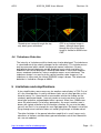
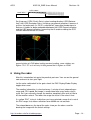
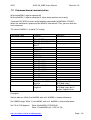
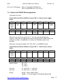
AOG
AOG SA_WXR Users Manual
Revision 1.6
SA_WXR as WXR 2100 simulation
The stand alone weather radar for MS-FS9
A detailed simulation of the Collins WXR2100 used in all major
airliners
Features:
-
Weather radar operation in WXR,WXR+T
-
Realistic beam simulation with tilt of +-15°, 3.5° beam with and Multiscan
simulation
-
Weather attenuation simulation, with 80NM Path Attenuation
Compensation (PAC) and corresponding alert (PAC ALERT)
-
Large clouds divided into “sub clouds” to display a realistic reflection
image for different altitude parts of the cloud
-
Overfly Protection (OFP) – extended thunderstorm visibility
-
Ground Reflection Simulation with simplified ground elevation model!
so weather can be hidden within ground reflections
-
Ground reflections compensation mode (GCS) for hiding ground
reflections
-
No need to set 3D clouds and image is not affected by limiting the cloud
visibility or density
-
Is able to export Project Magenta WXR Data to include Radar image into
the PM Navigation Displays
http://members.chello.at/addongauges
Page - 1 -
AOG
AOG SA_WXR Users Manual
Revision 1.6
1 Introduction
Modern cockpits are more and more “plug and play” able. I mean that the pilot
needs not to understand many of the technical basics and principles that are
used for building avionics. Compare the complete checklist procedures from a
747-200 and a A340. Hmm think the airbus pilot is much faster… But there is one
avionic which is not becoming simplified with growing age. It is the weather radar.
The usage of a weather radar needs to understand the technical principle of a
radar as well as a good meteorological basics. And you have to consider all
these principles when changing any parameter or when you interpret the
displayed image. A weather radar really increases the workload and so the fun
while flying the simulator.
Realizing a weather radar for MSFS is not as simple as any other avionic,
because there is no reasonable way to find out the position of single clouds. But
the distributed weather station principle of the MSFS9 opens the way to display
certain areas where a certain weather is present. And if this area consists of
clouds (and many more meteorological data) that would generate weather radar
reflections on a real weather radar, a typical realistic reflection image is drawn at
this area. For wider range and strategic weather avoidance this is far enough.
But flying through single red areas would not be realistic and would not make
sense, because they are not representing a single thunder cloud!. But as you use
the AOG SA_WXR you will see this is far enough for good weather radar
operation and simulation. The many different simulated controls and realistic
graphic and meteorological parameters gives you a real weather radar
experience.
The number of home cockpit builders is steadily increasing, and me is also flying
with a semi professional partial homebuilt. And my target was to create a realistic
and professional weather radar for those advanced sim users.
So let this documentation tell you the principles of weather radar, about the
realization for MSFS with AOG SA_WXR and how to install and run in connection
with Project Magenta.
much fun with the docu and finally with the AOG SA_WXR
Florian Praxmarer
http://members.chello.at/addongauges
Page - 2 -
AOG
AOG SA_WXR Users Manual
Revision 1.6
2 Contents
1
2
3
4
5
6
7
8
9
Introduction.......................................................................................................... 2
Contents .............................................................................................................. 3
Setup and Configuration...................................................................................... 4
3.1
Key assignment............................................................................................ 4
3.2
The config file ............................................................................................... 4
3.3
SA_WXR embedded in Project Magenta Navigation Displays ..................... 5
Weather radar basics .......................................................................................... 7
4.1
Principles of operation.................................................................................. 7
4.2
The Beam..................................................................................................... 8
4.3
Weather attenuation and PAC...................................................................... 9
4.4
Ground clutter reflections ........................................................................... 10
4.5
Meteorological Basics ................................................................................ 11
4.6
Turbulence Detection ................................................................................. 13
Limitations and simplifications ........................................................................... 13
Using the radar.................................................................................................. 14
FSUIPC Control................................................................................................. 15
7.1
Control variations ....................................................................................... 15
7.2
Command based communication ............................................................... 16
7.3
Control via FSUIPC Bit manupulation ........................................................ 17
7.4
FSUIPC registration ................................................................................... 19
Product Licensing .............................................................................................. 19
System requirements......................................................................................... 19
http://members.chello.at/addongauges
Page - 3 -
AOG
AOG SA_WXR Users Manual
Revision 1.6
3 Setup and Configuration
3.1 Key assignment
Function
Key
Assigned PM
parameter
Position Radar
Cursor Keys
None
Zoom Radar
Num +/Num -
None
Toggle
OFF/WXR/WX+TRUB
F1
FMC LSK1L
Toggle OFP
F2
FMC LSK2L
Toggle GCS
F3
FMC LSK3L
Refresh PM ND
F4
FMC LSK4L
Tilt Increase
F7
FMC LSK1R
Tilt Reset to 0
F8
FMC LSK2R
Tilt decrease
F9
FMC LSK3R
Rang increase decrease
R/T or F5/F6
Remarks
Ctrl and Cursor for fast
movments
Ctrl and +/- for fast
zooming
WARMUP Initially
Only available in
Simulate current PM
WX Mode = 1
Limited from 10NM to
PM ND Range or
320NM, affected by
FMC LSK5L and LSK6L
config file entry
The position setup is saved as the program is closed, and is used next time
started again.
3.2 The config file
In the sa_wxr.cfg some user defined configurations have to be set:
Keep the same order as here listened, else you will get a configuration file error.
Do not delete any items, only change the parameters.
First is the alternate window entry:
Alternate Window Name = BFMSCDU
This “BFMSCDU “ is valid for the PM Boeing Captain FMS for example. This tells
the Program that it should switch to the Window called “BFMSCDU” when not
active. You find out the string when running any target application and enter the
Taskmanager (Alt+Ctrl+Del), and see how the target application is named there.
Type this string exactly in here and it would work.
http://members.chello.at/addongauges
Page - 4 -
AOG
AOG SA_WXR Users Manual
Revision 1.6
TitleBar visible = 1
This entry shows (1) or hides (0) the tile bar of the application.
Focus Change Event = 0
0 means use the SA_WXR FSUIPC location, see end of document
1 means use the PM TCAS Flag (TCAS = On to display the WXR)
if the selected event location is toggled the radar switches between the window
mentioned in the “Alternate Window Name “ entry and itself.
Bitmap Export Directory =
You can specify an bitmap export directory here. If a path is entered here,
>>C:\radarexport\<< for example, then a 256x256 pix large bitmap (wx.bmp) is
exported every time the radar refreshes. This feature can be used to import
radar images into navigation displays. See the FSUIPC section of this document
also. Leave blank to disable this function.
Disable Output when in Bitmap Export Mode = 0
If previous path is supplied, then you can additionally disable the radar image
display output, by setting this Flag to 1. This option saves power on the PC.
Get PM Range = 0
As I found some troubles reading the PM Range variable in some PM
configurations, you can override it here and set the range manually with the
assigned keys or LSK’s.
Simulate current PM WX Mode = 1
If you want to make the WXR Image make visible in your Project Magenta
Navigation Display then set this Flag to “1”. Additionally set the Bitmap Export
Directory entry (described above) to the NetDir of your Project Magenta Network.
Set PM Update Rate = 7
This parameter sets the update rate of the PM exported image in refresh cycles.
One refresh cycle is about 8 seconds, so expect 56 sec. updates as default.
Making the value smaller results in more updates but also in more glass cockpit
stutter. Find a usable setting for your GC CPU, but 6-7 is a practical value.
3.3 SA_WXR embedded in Project Magenta Navigation Displays
You have the possibility to make the weather radar image visible in the Project
Magenta Software Navigation Displays. Although there are a few limitations you
will get a very realistic weather display experience. Until now the Project
Magenta System uses Satellite images for weather data. Now the SA_WXR
http://members.chello.at/addongauges
Page - 5 -
AOG
AOG SA_WXR Users Manual
Revision 1.6
exports the its weather radar data. I think this combination is the best solution for
airliner weather radar simulation. Since the transfer of the image data is done via
a data file in the PM NetDir folder, there is following limitation. The radar image
displayed in the ND can not be updated every 8 seconds, since this would make
the PM GC stuttering, because of the many file accesses. It is reloaded every
1min. But the image is moved along with the aircraft translation and rotation, this
does not generate any offsets. And whenever a change in the settings is done,
the image is also updated within the next beam rotation.
Following setup should be done for proper PM interfacing:
-
Download the newest GC Version of your Product
-
Do not install the SA_WXR and the GC on the same PC, it is best to install the
SA_WXR on the FMC PC anyway
-
Make following SA_WXR.cfg setup
Bitmap Export Directory = >>enter your PM NetDir here<<
Enter the NetDir without last Backslash C:\PmNetDir for example
Disable Output when in Bitmap Export Mode = 1
You should disable the SA_WXR display output since it only costs
performance and will not be useful for you in this mode
Get PM Range = 1
So you lock the WXR Range to the ND range.
Simulate current PM WX Mode = 1
Bring the SA_WXR to PM Export mode.
Set PM Update Rate = 7
Set the update rate as best working for you, 6-7 as default works in most
configurations
-
PM displays now the WXR image and the tilt angle, but the tilt setup and the
OFP and GCS function have to be set on the SA_WXR screen or via FSUIPC
as described below
http://members.chello.at/addongauges
Page - 6 -
AOG
AOG SA_WXR Users Manual
Revision 1.6
4 Weather radar basics
4.1 Principles of operation
The target of a weather radar is to display the pilot hazardable and turbulent
meteorological areas. A ideal weather radar would display following hazards as
dense precipitation (hail), turbulent precipitation moves (updrafts within
thunderstorms), thunderstorms itself, low visibilities, wind shears, any clouds
etc.
The real solution is limited to only display precipitation density (density of
ice/water particles).
So a real weather radar does not display clouds, fog, winds, storms etc. it only
displays the density of precipitation in the air around you.
A weather radar transmits a focused microwave pulse into the sky. A part of the
microwave energy sent out is (similar to light) reflected when it hits a particle.
Some particles reflect more (for light this would be a mirror) some reflect very
few energy (glass for light).
The microwave from a weather radar is reflected best when hitting water (rain)
or wet hail, and is very weak reflected from drizzle and snow general ice
particles.
After the radar has sent out a pulse, it now measures how long it takes until a
part of energy is received, it measures the amount of the energy and the
frequency shift of the received signal.
Out of this data following can be obtained:
Time & Reflection Energy = Distance & Density of the particles
Frequency Shift = Velocity of the particles
This data is then displayed on the radar in three colors:
Green = weak density
Yellow = moderate density
Red = high density
Light magenta = moderate velocity changes (=turbulence)
Intense magenta = high velocity changes (=serve turbulence)
http://members.chello.at/addongauges
Page - 7 -
AOG
AOG SA_WXR Users Manual
Revision 1.6
4.2 The Beam
Beam Rotation Angle = 160°
positive tilt angle
zero tilt angle
negative tilt
Beam Tilt angle from –15° up to 15° in 0.25° steps
Beamwidth is 3.5° (+/- 1.75°)
http://members.chello.at/addongauges
Page - 8 -
AOG
AOG SA_WXR Users Manual
Revision 1.6
The beam is rotated by 160° from left to right and back, and while rotated it
sends continuously pulses out and receive them. So the beam covers a large
lateral area in front of the aircraft. This movement can not be controlled by the
pilot. The speed of the movement depends on the range and sensitivity
settings.
The beam tilt angle need to be set by the pilot. Only in OFP Mode the tilt is
swept automatically (see later). The tilt is independent of the pitch angle, that
is automatically compensated.
The beam is not ideally focused, for Collins WXR2100 the beamwidth is 3.5°.
You will see all reflections within this beam triangle. (a triangle is only a
simplified 3db slope)
4.3 Weather attenuation and PAC
It is very important to know that the radar signal gets weaker with increasing
distance from the aircraft. Additional the signal is attenuated by the reflection
and temperature and so on. That means that at high distance a thunderstorm
seems to produce less reflection as in near distance. You can see that
reflections getting more intense as coming closer to the object of interest.
The radar can compensate this effect within 80NM of range, that means within
this range reflections are true an will not change any more due to the
attenuation effects.
This range is called the Path Attenuation Compensation (PAC) range.
A warning is displayed when operating in ranges higher than 80NM to be aware
of this effect.
Radar setup 320 NM with a single thunderstorm coming toward for attenuation
demonstration. Tilt is adjusted to sense the lower third of the thunder cloud.
weak reflections 320NM away
http://members.chello.at/addongauges
reflections get more intense as getting
closer
Page - 9 -
AOG
AOG SA_WXR Users Manual
In 120-140NM distance first red reflections
Revision 1.6
And true image is drawn within the
80NM PAC range.
4.4 Ground clutter reflections
As the beam is hits the ground, it is very well reflected from water, metal
concrete and so on. So ground reflections are mostly shown as yellow and red
reflections.
In the example above the Thunderstorm is sensed by the radar, but it is also
surrounded by red and yellow reflections from the mountain. So increasing the
tilt would solve the problem. But as you see later, thunderstorms are only
visible at the lower 2/3 of the cloud, the top 1/3 is invisible for radar. So a tilt
increase would maybe also eliminate the storm on the display. Collins found
out a algorithm to compensate the ground reflection and so make only weather
data visible. This mode is called the Ground Clutter Suppression (GCS)
http://members.chello.at/addongauges
Page - 10 -
AOG
AOG SA_WXR Users Manual
hmm, find the storm in the ground
clutter
Revision 1.6
Here it is, switch on GCS
4.5 Meteorological Basics
What can be displayed on the radar ? As said above only wet particles
(raindrops, wet hail) produce good reflections. Now it is time to interpret
different precipitation densities and reflections.
Aviation based weather radars are as sensible to show only reflections that
are relevant for flight operations. Meteorological weather radars are much
more sensitive which may display nearly everything that’s in the sky.
But Aviation related weather phenomena are of course thunderstorms due to
their high turbulence inside and the relative heavy ice particles (hail). Also
clouds that may develop to a storm.
Other clouds are not really a hazard for aircrafts, and most of them do not
generate any reflections.
To find out thunderstorms on the radar it is important to know that such a
cloud has three precipitation stages.
altitude
3/3
2/3
1/3
The lowest third of the cloud consist of turbulent and fast moving heavy
raindrops. They are of course producing very good reflections. So you see a
red area when your beam crosses the bottom third of a cloud.
http://members.chello.at/addongauges
Page - 11 -
AOG
AOG SA_WXR Users Manual
Revision 1.6
As you increase the tilt and your beam cross the mid third of the cloud, where
the up moving raindrops freeze, you have also good reflections, but the area is
much smaller than in the bottom third. This because of the shape of a thunder
cloud.
At the top this of a thunder cloud hardly no reflections are generated because
it consists only of dry hail up there. As thunderstorm can reach high altitudes
they may grow up into your flightlevel. But there you will only cross the top
third of the cloud which will not be displayed on the radar when flying with
neutral tilt.
But tops of thunderstorm should be avoided because of the turbulent air above
them, and the hail particles within them. Therefore Collins has included the
thunderstorm OverFly Protection (OFP).
This function continuously changes the tilt and looks for high reflective
thunderstorm bodies (“bottom third’s”)
Independed of where your set tilt crosses the thunderstorm now, it always
draws the saved bottom image instead. So you always see great red areas
where storms are present, even if they would not create reflections with your
current settings.
This function is only available with in the PAC range, that is fixed to 80NM.
Other clouds than thunderstorms may also create reflections. Towering
cumulus clouds have the same characteristics as thunderstorms (also consists
of the three precip. parts) but reflections are only in the green and yellow
range.
Lower cumulus clouds also can create reflections because they consist of
water drops anyway. But density and turbulence is much lower than in thunder
clouds.
Additional low sized clouds (nimbostratus and similar) that consist of raindrops
also generate reflections. In most cases there is also downpour below them.
Thunder cloud sensed through the
bottom third
http://members.chello.at/addongauges
thunder cloud sensed through
the mid ( far reflections not
seen because of the tilt angle)
Page - 12 -
AOG
AOG SA_WXR Users Manual
Thunderstorm sensed through the top,
only weak green reflections
Revision 1.6
OFP is on, bottom image is
drawn, although beam goes
through the top of the cloud.
Image is limited to 80NM since
PAC.
4.6 Turbulence Detection
The intensity of turbulence within clouds can also be displayed. The turbulence
is calculated out of the velocity changes for the reflections. This turbulence can
only be measured within clouds that generate normal reflections. So only
precipitation based turbulence can be displayed, gusty winds and other air
turbulence can not be displayed. Following color code is used: dark magenta
means moderate turbulence, intense magenta means serve turbulence. The
turbulence image is an overlay to the normal weather radar image so if no
turbulence is measured, the normal RGB WX image is drawn. The turbulence
detection is limited to a Range of 40NM.
5 Limitations and simplifications
A few simplifications were necessary for weather radar display in FS9. First of
all is the cloud position. In reality red drawn holes are at same position as the
cloud of course. As I have found no reasonable solution for finding out the
randomly positioned clouds, I can only render a exact area where a certain
cloud type and other meteorological data is present. More than 12000 areas
cover the whole world. Out of many parameters, the exact weather area is
drawn with typical reflections for the weather situation. As you use the radar
you will see that it is far enough for save flight operation. But keep in mind that
flying through exact red holes does not avoid flying through a thunder cloud.
The other limitation is the ground elevation model that is used. I covers only
elevations of stations and calculates ground reflections out of that. Mountains
etc. are not modeled.
http://members.chello.at/addongauges
Page - 13 -
AOG
AOG SA_WXR Users Manual
Revision 1.6
LSZS 1600m
LSZH 428m
LIPB 237m
So flying over LSZH (Zurich Swiss) when heading direction LIPB (Bolzano
Italy) the LSZS (Samedan Swiss) will bring you ground reflections, because it
crosses the beam path. As GCS is switched off, a possible thunderstorm in
Bolzano is hidden or better embedded between the LSZS Ground reflection
and the LIBP ground reflection. Increasing the tilt and/or enabling the GCS
function would eliminate this effect.
ground clutter at LOWI when looking eastern heading, some stations are
higher. Tilt 1.75° so it will only hit that ground that is higher as LOWI.
6 Using the radar
After this introduction lets go to the practical part now. Your are on the ground
now and want to start your flight.
Let the radar switched off at the gate. check the FMC Display/Radar Display
toggle when used.
The weather information is refreshed every 1 minute at least, depending on
range and CPU speed. But image is recalculated after every beam refresh
cycle. So if you manually change the weather completely then wait at little to
let the weather refresh. The lower the range the faster is the refresh time.
If a yellow “PAC” string is visible then you have selected a range that is out of
the PAC range, that means reflections over 80NM are not accurate.
The colored boxes on the top of the radar show you the colors used for
drawing the image with the actual settings.
http://members.chello.at/addongauges
Page - 14 -
AOG
AOG SA_WXR Users Manual
Revision 1.6
When beginning taxi roll, switch the radar to WXR and let it warm up.
Depending on your processor speed this could take one to two minutes. Set tilt
up to 1.75 degrees to eliminate ground reflections. Range is taken from the
ND when used, else set 40NM-80NM initial.
The picture is refreshed every 8-10 seconds depending also on your
processor speed, but this is also a realistic value.
Do not take off directly into thunderstorms near the field, if possible
request turns immediately after take off to avoid.
If yellow reflections are present, check the turbulence with WX+TURB mode
and check. Taking off in heavy turbulence may causes stall speed exceeding
in initial climb out.
During climb try to set the tilt around your actual Flight Path angle, PM draw it
into the artificial horizon when enabled. Let the OFP switched on during the
whole flight, the GCS will become interesting during descent.
During Level flight you can leave the tilt neutral, but check the OFP is on!
Else you may be surprised by a tall thunder cloud.
When entering the descent phase, turn GCS on. So ground clutter is mostly
suppressed. Here it is up to you to find out good tilt values. You may set it to
your Flight Path Angle as during climb, or you can set it to find out weather to
any other point of interest. (IAF, rwy threshold etc)
7 FSUIPC Control
7.1 Control variations
Since it is difficult to fit all cockpit builders concepts, I had three different variations in
controlling SA_WXR:
1. Command based control (recommended) implemented since SA_WXR 1.2.4
Similar to Project Magenta’s ND commands.
2. Bit toggle based communication.
3. Bit state based communication
http://members.chello.at/addongauges
Page - 15 -
AOG
AOG SA_WXR Users Manual
Revision 1.6
7.2 Command based communication
Write to 0x6D00 1 byte for commands
Write to 0x6D01 1 byte for absolute tilt value (write positive values only)
To control SA_WXR functions write following commands to 0x6D00 in FSUIPC.
When the command is processed the 6D00 is cleared to 0. Then you can write the
next command.
Tilt value at 0x6D01 is used for Tilt setting.
Command Value
Function
1
2
3
RADAR OFF
RADAR ON/ MODE WXR
RADAR ON/ MODE
WX+T
5
6
GCS OFF
GCS ON
7
8
OFP ON
OFP OFF
9
10
11
12
13
14
RANGE 10NM
RANGE 20NM
RANGE 40NM
RANGE 80NM
RANGE 160NM
RANGE 320NM
15
16
RANGE increase
RANGE decrease
17
SET Tilt of 0x6D03
positive
SET tilt of 0x6D03
negative
18
Remarks
Warmup phase initially
0-40 (equals 0-15 deg in
0.25 deg steps)
0-40 (equals 0-15 deg in
0.25 deg steps) but is
written negative then
Examples:
Switch radar on: Write 2 to 0x6D00, wait until 0x6D03 is cleared afterwards
Set 160NM range: Write 13 to 0x6D00, wait until 0x6D03 is cleared afterwards
Set Tilt of 2.25 degrees:
Write 9 to 0x6D03 (2.25/0.25=9)
Write 17 to 0x6D00 (set +2.25° of Tilt)
http://members.chello.at/addongauges
Page - 16 -
AOG
AOG SA_WXR Users Manual
Revision 1.6
Set Tilt of -5.25 degrees: Write 21 to 0x6D03 (5.25/0.25=21)
Write 18 to 0x6D00 (set -5.25° of Tilt)
7.3 Control via FSUIPC Bit manupulation
Two words are used:
Control-Word at (Write) 0x6D00 as long as Bit 7 = 0 which means toggle
mode
Bit7
Toggle/
Switch
select
(0)
Bit6
Range
dec
Bit5
Range
inc
Bit4
Bit3
Toggle
OFP
Bit2
Toggle
GCS
Bit1
Set to 1
Bit0
Toggle
Mode
Bit15
Res.
Bit14
Res.
Bit13
Res.
Bit12
Res.
Bit11
Toggle
Window
Bit10
Tilt dec
Bit9
Tilt reset
Bit8
Tilt inc
Whenever you write here set bit 1 to “1”, else the radar would ignore the
requests. These bits are toggled, that means setting a bit to 1 would request the
action at the radar, if recognized it is set back to 0. Multiple requests are
possible.
Bit0 witches through the Modes OFF, WX, WX+T or WARMUP initially.
Control-Word at (Write) 0x6D00 as long as Bit 7 = 1 which means switch
mode
Bit7
Toggle/
Switch
select
(1)
Bit6
Range2
Bit5
Range1
Bit15
Tilt7
Bit14
Tilt6
Bit13
Tilt5
Bit4
Bit3
Bit2
Bit1
Range0 OFP ON GCS ON Mode 1
Bit12
Tilt4
Bit11
Tilt3
Bit10
Tilt2
Bit9
Tilt1
Bit0
Mode 0
Bit8
Tilt0
Mode0, Mode1
00 = OFF
01 = WX
10 = WX+T
GCS ON
OFP ON
0 = GCS OFF, 1 = GCS ON
0 = OFP OFF, 1 = OFP ON
Range:
Range = (Bit4+2*Bit5+4*Bit6)
Range = 1,2,3,4,5,6 equals 10,20,40,80,160,320 NM
http://members.chello.at/addongauges
Page - 17 -
AOG
AOG SA_WXR Users Manual
Revision 1.6
Tilt0 – Tilt7 (signed byte) in 0.25° steps (so to get the tilt angle multiply the signed
byte value with 0.25)
If you write –40 then the tilt would be –40*0.25= -10°
Status Byte at (Read) 0x6D02
Bit7
Window
active
Bit6
Range2
Bit5
Range1
Bit4
Bit3
Range0 OFP ON
Bit2
GCS
ON
Bit1
Mode 1
Bit0
Mode 0
Status:
Mode0, Mode1
00 = OFF
01 = WX
10 = WX+T
GCS ON
OFP ON
0 = GCS OFF, 1 = GCS ON
0 = OFP OFF, 1 = OFP ON
Range:
Range = (Bit4+2*Bit5+4*Bit6)
Range = 1,2,3,4,5,6 equals 10,20,40,80,160,320 NM
Window active
0 = not active
1 = active
Tilt Window at 0x6D03
Bit7
Tilt7
Bit6
Tilt6
Bit5
Tilt5
Bit4
Tilt4
Bit3
Tilt3
Bit2
Tilt2
Bit1
Tilt1
Bit0
Tilt0
Tilt0 – Tilt7 (signed byte) in 0.25° steps (so to get the tilt angle multiply the signed
byte value with 0.25)
If you read –40 then the tilt would be –40*0.25= -10°
Bitmap export offsets:
0x6D04 4byte signed long Latitude of exported bitmap in deg * 1000000
0x6D08 4byte signed long Longitude of exported bitmap in deg * 1000000
0x6D0C 4byte signed long Heading of exported bitmap in deg * 65536
N and E is positive, S and W is negative
if a image is drawn at N47.6542 W11.5422 and Heading 250° then following
signed long values would be present:
0x6D04
0x6D08
47654200
-11542200
http://members.chello.at/addongauges
Page - 18 -
AOG
AOG SA_WXR Users Manual
0x6D0C
Revision 1.6
16384000
7.4 FSUIPC registration
If you have unregistered Version of FSUIPC please register the software
manually with:
“sa_wxr.exe”
and the key NQIWBXJU6M88
8 Product Licensing
After successful purchase at simmarket etc. you can download the whole
installation package there.
After successful installation run the sa_wxr program. After a few seconds, and
Dialog appears with a all your installed MAC Addresses of your computer. Copy
and paste them into a e-mail and send to [email protected] Then a
license is sent to you within 24hrs.
Attention, when changing network adaptor, you have to be relicensed, of course
free.
9 System requirements
Minimum System requirements are:
PII 200Mhz or better
More than 64MB free memory
3D-Graphics board, but can be on PCI
WideFS and FSUIPC >3.0
FS2004 on the server PC
1 installed and activated Ethernet board for licensing
http://members.chello.at/addongauges
Page - 19 -