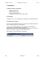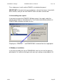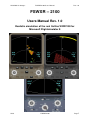
1
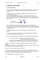
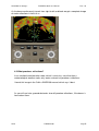
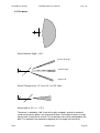
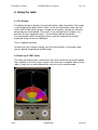
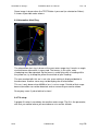
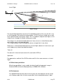
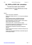
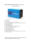
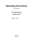
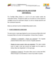
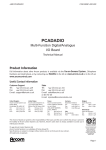
AOG Add On Gauges
FSWXR-2100 Users Manual
Rev. 1.0
FSWXR – 2100
Users Manual Rev. 1.0
Realistic simulation of the real Collins WXR2100 for
Microsoft Flightsimulator 9
AOG
FSWXR2100
Page 1
AOG Add On Gauges
FSWXR-2100 Users Manual
Rev. 1.0
1. Introduction
Weather is the one of uncontrollable factors in aviation. Therefore a precise weather
analysis is necessary for a safe aircraft operation. Most of the work is done before
flying, in a detail weather forecast. But nevertheless weather is changing, often in a
not forecasted manner. Most important is to locate hazardous weather areas, and
avoid them. That’s now where the weather radar system comes into play.
This system is able to show the pilot where dense precipitation is located and
turbulence is expected.
Of course, weather is also an important factor in flight simulation. With the release of
Microsoft Flight Simulator 9, Microsoft has built an outstanding weather engine.
Together with perfect weather add-ons (AS e.g.) weather becomes as important and
uncontrollable as in reality.
So in flight simulation weather radar also would be important. But since the Microsoft
flight simulator does not simulate in could turbulence and precipitation, there is no
reasonable way to program a radar.
But anyway, weather radar simulation is possible, because we do what Microsoft has
not implemented yet. We are going to assume precipitation in clouds and display
that. In-cloud precipitation depends on certain meteorological conditions, what we do
is to analyse the meteorological situation and out of that we determine the amount of
precipitation there would be in reality. The algorithm for that has been worked out
together with meteorologists.
Functions and displaying of that precipitation data is based on the Rockwell Collins
WXR-2100 weather radar, used in many major airliners (B737 up to B777, all Airbus)
The weather radar avionic itself is very complex to use and needs detailed
understanding of its principle. It is not a “watch and trust” avionic as TCAS for
example. The weather radar image depends mostly on its setup, which is done by the
pilot.
So many good reasons to use a weather radar system in flight simulator, which will
increase your workload, increase your aviation knowledge and so fun on flying.
I want to thank you that you have purchased the gauge and wish you many funny
hours on flying with realistic weather radar usage in your cockpit
Praxmarer Florian
Add On Gauges
AOG
FSWXR2100
Page 2
AOG Add On Gauges
FSWXR-2100 Users Manual
Rev. 1.0
2. Contents
1.
2.
3.
Introduction.......................................................................................................... 2
Contents .............................................................................................................. 3
Installation ........................................................................................................... 4
3.1
Minimum System requirements .................................................................... 4
3.2
Installation .................................................................................................... 4
3.3
Installation into a panel................................................................................. 4
3.4
Uninstalling from a panel.............................................................................. 6
3.5
Modify an installation.................................................................................... 6
4. Weather radar basics .......................................................................................... 7
4.1
Functional basics.......................................................................................... 7
4.2
What produces reflections?.......................................................................... 8
4.3
The beam ..................................................................................................... 9
4.4
Attenuation effects...................................................................................... 10
4.5
Ground clutter reflections ........................................................................... 11
4.6
Meteorological Basics ................................................................................ 12
4.7
Turbulence Detection ................................................................................. 14
4.8
Wind shear prediction PWS ....................................................................... 15
4.9. Limitations and simplifications........................................................................ 16
5. The FSWXR Gauge and Controls ..................................................................... 17
5.1 The Boeing style ............................................................................................. 17
5.2 The Airbus style .............................................................................................. 18
6. Using the radar.................................................................................................. 19
6.1
The Display ................................................................................................ 19
6.2
Power up & TEST mode............................................................................. 19
6.3
Attenuation Alert Ring ................................................................................ 20
6.4
Tilt setup..................................................................................................... 20
6.5
Wind shear prediction................................................................................. 21
6.6
Performance............................................................................................... 21
AOG
FSWXR2100
Page 3
AOG Add On Gauges
FSWXR-2100 Users Manual
Rev. 1.0
3. Installation
3.1 Minimum System requirements
•
•
•
•
Windows 2000 or newer
64MB of free memory
Microsoft Flight simulator 9
Unregistered FSUIPC.dll Version 3.0 or newer
3.2 Installation
Installation is easy, since the software is installed by an self extracting exe file.
3.3 Installation into a panel
You can install the FSWXR into any panel you like. The installation is kept easy
with the FSWXR2100 Panel Installer program.
If you install the FSWXR2100 the first time, the panel installer program is
launched after a successful installation automatically.
If you want to install FSWXR-2100 into a panel at a later time, or if you want to
modify an installation, you find the installer program under:
Start>Programs>AOG>FSWXR Panel Configurator
AOG
FSWXR2100
Page 4
AOG Add On Gauges
FSWXR-2100 Users Manual
Rev. 1.0
The installer looks like this:
Initially the directory box points to your FS9\aircraft folder. All you installed
aircrafts are visible.
You now can select the aircraft you want to install the FSWXR2100 to.
Double click on the target aircraft (B747_400 in our example) and then double
click on the appearing panel folder.
If there is a valid panel.cfg file found the installer enables the “INSTALL” button
and the option controls.
You can select between 3 different styles:
•
•
•
AOG
Boeing heavy style, normally used in 747,757,767,777
Boeing grew style 737, used in the whole 737NG series and it is the most
common style for all other aircrafts
Airbus style, as used in all Airbus aircrafts, that have the Collins WXR2100
included.
FSWXR2100
Page 5
AOG Add On Gauges
FSWXR-2100 Users Manual
Rev. 1.0
Then simply press install and the FSWXR is installed to that panel.
IMPORTANT! If the panel that you installed to is aliased, that means shared with
other aircrafts, than you will see FSWXR-2100 in the other aircrafts too!
3.4 Uninstalling from a panel
If you want to remove the FSWXR-2100 from a panel, then again select the
aircrafts panel folder as described at 3.3. The Installer automatically detects an
FSWXR2100 installation and looks like this:
Simple press “REMOVE…” and FSWXR2100 is removed from the target panel.
3.5 Modify an installation
If you want to modify the style of FSWXR2100, then first uninstall the panel as
described in 3.4 and the install again with new style settings as described in 3.3
AOG
FSWXR2100
Page 6
AOG Add On Gauges
FSWXR-2100 Users Manual
Rev. 1.0
4. Weather radar basics
4.1 Functional basics
A weather radar is intended to show the pilot hazardous weather situations, such
as heavy turbulence, thunderstorms, wind shear. But that’s no as easy as it
sounds.
The only way to scan for something around the aircraft is to sense for radar
reflective particles in the air.
In a certain radar frequency range, water is such a reflective subject. So a
weather radar can only sense for water particle in the air. But as you see later,
water at a certain density is seen within thunderstorms, so this is a good way too
sense for them.
Radar energy disturbed
Radar beam
If the radar beam hits a reflective particle (blue circle) it is disturbed into any
direction. Some small amount is directly disturbed back to transmitter (red arrow).
The denser the particle is (the more reflective it is) the less energy can go through
it (green arrow).
The weather radar now measures all energy that is directly return to it (red
arrows).
The radar energy needs a little time to travel out, be reflected and travel back.
The farer the distance the longer it takes.
Out of the received energy, the radar system can now determine following data:
•
•
•
The amount of reflected energy is the reflectivity of the particle
(Density of water particles in our case)
The time until the reflected energy is back is the distance of the particle
The frequency of the reflected energy is the moving speed of the particle
So with a weather radar we are able to determine how dense water is at which
distance.
Additional we can determine at which speed the particles are moving, which is similar
to the turbulence that may be expected there.
Based on this data, the radar image is now drawn.
The amount of energy received, so the density of water is separated by colour.
Green stands for lower water particles density, yellow for more dense water particles,
and red is for highly dense water particles (could also be wet hail).
This coloured point is now drawn on the map.
AOG
FSWXR2100
Page 7
AOG Add On Gauges
FSWXR-2100 Users Manual
Rev. 1.0
As the beam continuously travels from right to left and back we get a complete image
of water reflections in front of us.
4.2 What produces reflections?
In an aviation based weather radar, which is much less sensitive than a
meteorological weather radar, only water and wet hail produces reflections.
I found this image in the Collins WXR2100 manual which says it best:
As you will see later, ground obstacles also will produce reflections, if the beam is
focused on them.
AOG
FSWXR2100
Page 8
AOG Add On Gauges
FSWXR-2100 Users Manual
Rev. 1.0
4.3 The beam
Beam Rotation Angle = 160°
positive tilt angle
Zero tilt angle
negative tilt
Beam Tilt angle from –15° up to 15° in 0.25° steps
Beam width is 3.5° (+/- 1.75°)
The beam is rotated by 160° from left to right and back, and while rotated it
sends continuously pulses out and receive them. So the beam covers a large
lateral area in front of the aircraft. This movement can not be controlled by the
pilot. The speed of the movement depends on the range and sensitivity
AOG
FSWXR2100
Page 9
AOG Add On Gauges
FSWXR-2100 Users Manual
Rev. 1.0
settings. (In the FSWXR it needs 160 frames for one rotation, which needs
about 8 seconds@ 18fps as in reality)
The beams tilt angle need to be set by the pilot. Only in OFP Mode the tilt is
swept automatically (see later). The tilt is independent of the pitch angle that is
automatically compensated.
With the tilt you can vary the sensing altitude of at a certain point of interest.
Since tilting is a little complex, it is described in the “usage” section.
The beam is not ideally focused, for Collins WXR2100 the beam width is 3.5°.
You will see all reflections within this beam triangle. (A triangle is only a
simplified 3db slope).
4.4 Attenuation effects
Attenuation is one of the major effects that have to be considered by the pilot.
Well understanding of the following section is mandatory!
Radar shadowing:
Radar beam
If the beam hits dense water bodies (almost thunderstorms) a great amount of the
beam energy is disturbed. As you see, the green arrow is the remaining beam
energy after the first particle. It is the fully disturbed at the next particle, leaving no
energy for the last particle.
So the first two particles are drawn on the screen but the last one is not, because
it is not sensed.
That is important to know! Imagine there is a heavy thunder cloud followed by an
other. The second one is not displayed, since the first one disturbs all the energy.
Examples are shown later below.
Path attenuation:
Since the radar beam gets weaker by distance, the reflected energy of far
particles is lower than that of near particles. That means that the same particle
seems to be less dense at high distances. This could cause that a thunderstorm
be displayed in green, becoming red as it gets closer.
The WXR-2100 radar has a path attenuation compensation within 80NM, that
means within 80NM it all particles are displayed in their real colour.
A warning is displayed when operating at distances greater than 80NM.
AOG
FSWXR2100
Page 10
AOG Add On Gauges
FSWXR-2100 Users Manual
Rev. 1.0
4.5 Ground clutter reflections
As the beam is hits the ground, it is very well reflected from water, metal
concrete and so on. So ground reflections are mostly shown as yellow and red
reflections.
In the example above the Thunderstorm is sensed by the radar, but it is also
surrounded by red and yellow reflections from the mountain. So increasing the
tilt would solve the problem. But as you see later, thunderstorms are only
visible at the lower 2/3 of the cloud, the top 1/3 is invisible for radar. So a tilt
increase would maybe also eliminate the storm on the display. Collins found
out an algorithm to compensate the ground reflection and so make only
weather data visible. This mode is called the Ground Clutter Suppression
(GCS)
Without GCS
AOG
and finally with GCS
FSWXR2100
Page 11
AOG Add On Gauges
FSWXR-2100 Users Manual
Rev. 1.0
4.6 Meteorological Basics
What can be displayed on the radar? As said above only wet particles
(raindrops, wet hail) produce good reflections. Now it is time to interpret
different precipitation densities and reflections.
Aviation based weather radars are as sensible to show only reflections that
are relevant for flight operations. Meteorological weather radars are much
more sensitive which may display nearly everything that’s in the sky.
But aviation related weather phenomena are of course thunderstorms due to
their high turbulence inside and the relative heavy ice particles (hail), and
clouds that may develop to a storm.
Other clouds are not really a hazard for aircrafts, and most of them do not
generate any reflections.
To find out thunderstorms on the radar it is important to know that such a
cloud has three precipitation stages.
altitude
3/3
2/3
1/3
The lowest third of the cloud consist of turbulent and fast moving heavy
raindrops. They are of course producing very good reflections. So you see a
red area when your beam crosses the bottom third of a cloud.
As you increase the tilt and your beam cross the mid third of the cloud, where
the up moving raindrops freeze, you have also good reflections, but the area is
much smaller than in the bottom third. This because of the shape of a thunder
cloud.
At the top this of a thunder cloud hardly no reflections are generated because
it consists only of dry hail up there. As thunderstorm can reach high altitudes
they may grow up into your flight level. But there you will only cross the top
third of the cloud, which will not be displayed on the radar when flying with
neutral tilt.
But tops of thunderstorm should be avoided because of the turbulent air above
them, and the hail particles within them. Therefore Collins has included the
thunderstorm OverFly Protection (OFP).
AOG
FSWXR2100
Page 12
AOG Add On Gauges
FSWXR-2100 Users Manual
Rev. 1.0
This function continuously changes the tilt and looks for high reflective
thunderstorm bodies (“bottom third’s”)
In depended of where your set tilt crosses the thunderstorm now, it always
draws the saved bottom image instead. So you always see great red areas
where storms are present, even if they would not create reflections with your
current settings.
This function is only available with in the PAC range that is fixed to 80NM.
Other clouds than thunderstorms may also create reflections. Towering
cumulus clouds have the same characteristics as thunderstorms (also consists
of the three precipitation stages) but reflections are only in the green and
yellow range.
Lower cumulus clouds also can create reflections because they consist of
water drops anyway. But density and turbulence is much lower than in thunder
clouds.
Additional low sized clouds (nimbostratus and similar) that consist of raindrops
also generate reflections. In most cases there is also downpour below them.
AOG
FSWXR2100
Page 13
AOG Add On Gauges
FSWXR-2100 Users Manual
Rev. 1.0
Above you can see the three states of a thunder cloud, real WXR-2100 radar
images compared to the FSWXR2100 images.
The first pair is sensed through the top third of the cloud, and you see its low
reflective and hardly visible. (Although there are the most dangerous hail particles
and turbulences)
The second pair is sensed through the freezing hail area, the mid third of the
cloud. You see greater reflections.
The last pair is sensed through the bottom. You see red reflections and additional
ground clutter in the real image that is situation depended.
Now the same image within the OFP range:
As you see the OFP stored the most reflective bottom cloud part and displays it.
You can tilt now wherever you want, the red image stays here.
4.7 Turbulence Detection
The intensity of turbulence within clouds can also be displayed. The turbulence
is calculated out of the velocity changes for the reflections. This turbulence can
only be measured within clouds that generate normal reflections. So only
precipitation based turbulence can be displayed, gusty winds and other air
turbulence can not be displayed. Following color code is used: dark magenta
means moderate turbulence, intense magenta means serve turbulence. The
turbulence image is an overlay to the normal weather radar image so if no
turbulence is measured, the normal RGB WX image is drawn. The turbulence
detection is limited to a Range of 40NM.
AOG
FSWXR2100
Page 14
AOG Add On Gauges
FSWXR-2100 Users Manual
Rev. 1.0
Serve turbulence to be expected in the magenta area!
4.8 Wind shear prediction PWS
A special high sensitivity mode makes it possible to detect wind shear out of water
particles. Wind shear is always present at low altitudes just above ground.
Additional due to the high sensitivity, other particles than water may produce
enough reflection energy to be detected and displayed as wind shear.
Wind shear is only working below 2500ft AGL and in ranges up to 5NM. This
mode is only intended for take off and final approach phase.
Wind shear areas are marked by red rings.
AOG
FSWXR2100
Page 15
AOG Add On Gauges
FSWXR-2100 Users Manual
Rev. 1.0
4.9. Limitations and simplifications
A few simplifications were necessary for weather radar display in FS9. First of
all is the cloud position. In reality red drawn holes are at same position as the
cloud of course. As I have found no reasonable solution for finding out the
randomly positioned clouds, I can only render an exact area where a certain
cloud type and other meteorological data is present. More than 12000 areas
cover the whole world. Out of many parameters, the exact weather area is
drawn with typical reflections for the weather situation. As you use the radar
you will see that it is far enough for save flight operation. But keep in mind that
flying through exact red holes does not avoid flying through a thunder cloud.
The other limitation is the ground elevation model that is used. It covers only
elevations of stations and calculates ground reflections out of that. Mountains
etc. are not modeled.
LSZS 1600m
LSZH 428m
LIPB 237m
So flying over LSZH (Zurich Swiss) when heading direction LIPB (Bolzano
Italy) the LSZS (Samedan Swiss) will bring you ground reflections, because it
crosses the beam path. As GCS is switched off, a possible thunderstorm in
Bolzano is hidden or better embedded between the LSZS Ground reflection
and the LIBP ground reflection. Increasing the tilt and/or enabling the GCS
function would eliminate this effect.
AOG
FSWXR2100
Page 16
AOG Add On Gauges
FSWXR-2100 Users Manual
Rev. 1.0
5. The FSWXR Gauge and Controls
5.1 The Boeing style
(10)
(9)
(8)
(7)
(1)
(2)
(4)
(3)
(5)
(6)
(1) Gain Knob, not working in this release
(2) Power button
(3) Test mode (unselects WXR or WX+T), test image is drawn
(4) WXR mode (unselects TST or WX+T), 3 colour WXR image is drawn
(5) Wind shear prediction mode, wind shear is drawn only when range <=20NM
and aircraft is 2500ft AGL or below
(6) Ground Clutter Suppression switch, selects GCS function
(7) Tilt Knob, for selecting a tilt
(8) WX+T mode (unselects WX+T or TST), 5 colour WXR image is draw,
including turbulence display
(9) Range increase area, clicking this area range is increased
(10)Range decrease area, clicking this area decreases range.
AOG
FSWXR2100
Page 17
AOG Add On Gauges
FSWXR-2100 Users Manual
Rev. 1.0
5.2 The Airbus style
(1)
(2)
(4)
(6)
(8)
(7)
(6)
(5)
(1)
(2)
(4)
(3)
(1) Gain Knob, not working in this release
(2) Power switch
(3) Wind shear prediction switch, wind shear is drawn only when range <=20NM and
aircraft is 2500ft AGL or below
(4) Radar Mode Selector, same as Boeing (3), (4), (8)
(5) Ground Clutter Suppression switch, selects GCS function
(6) Tilt Knob, for selecting a tilt
(7) Range increase area, clicking this area range is increased
(8) Range decrease area, clicking this area decreases range.
In reality the aircrafts can have different control panels installed depending on
weather radar manufactor and version. These are the common ones.
AOG
FSWXR2100
Page 18
AOG Add On Gauges
FSWXR-2100 Users Manual
Rev. 1.0
6. Using the radar
6.1 The Display
The display of course displays the sensed weather radar information. The image
is refreshed with the beam travel. Since a multi sensing weather radar, like the
Collins WXR 2100, always draws a image out of memory, change any control is
delayed by one travel period. That means if you change the tilt, range or any
function, but they take place after (!) the next beam period (8seconds).
The annunciators within the display always show the setup for the actually
displayed image (so are also delayed).
That is important to know!
So whenever you change a control, wait until annunciators in the image show
correct, before interpreting the WXR image.
6.2 Power up & TEST mode
The radar pulse generators need to warm up, which could take up to 40 seconds.
After a power on the test image is drawn until warm-up is complete. After that the
radar is ready for use and automatically switches to the selected mode.
AOG
FSWXR2100
Page 19
AOG Add On Gauges
FSWXR-2100 Users Manual
Rev. 1.0
Same image is drawn when the TEST Button is pressed (or selected on Airbus).
It shows all possible radar colours.
6.3 Attenuation Alert Ring
The attenuation alert ring is drawn at the most outer range ring. It marks an angle
at which beam attenuation is measured. That means in this area, radar
shadowing must be expected. So that means, avoid flying with a heading within
the yellow arc, try to keep the yellow line outside of your heading.
The area marked with this arc is not safe, even nothing is displayed behind a
thunderstorm. Another storm may not be display due to attenuation!
This arc is only drawn when 80NM or less is set as range. Outside of that range
beam attenuation can not be detected, and so no warning arc can be drawn.
So anyway never fly close behind a storm!
6.4 Tilt setup
A proper tilt setup is mandatory for weather radar usage. The tilt is the parameter,
with that you control where you want observe at a certain altitude.
AOG
FSWXR2100
Page 20
AOG Add On Gauges
FSWXR-2100 Users Manual
Rev. 1.0
Level Flight:
3
2
1
Radar Range
For normal flight operations the case (2) should be aimed. In this case the tilt is set
as to hit ground at the end of the range display. If GCS is off you should see a small
arc of ground clutter at the outer range. This is a good tilt setup for level flight, as this
setup senses through all altitudes along your range.
The setup (1) is not recommended, because it only senses a short distance (blue
line) and the rest is only ground clutter.
This setup could be useful to temporary aim on a target that is very close.
Setup (3) is a not recommended, because in level flight, because in most cases you
sense above any interesting cloud formations.
Take off:
For take off, it’s best to leave neutral tilt, and switch GCS on.
Approach:
For approaches switch off the GCS function and tilt in the same manner as in level
flight.
6.5 Wind shear prediction
Wind shear prediction is only usable for take off and final approach, range is
limited to 5NM and can be displayed only at 2500ft AGL or below.
6.6 Performance
The FSWXR2100 normally don’t hit the frames, but that depends on the screen
size. Reduce radar size as much as possible, then frame performance is best.
AOG
FSWXR2100
Page 21