1
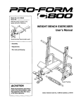
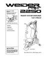
Model No. 831.159300
Sedal No.
Write the serial number in the
space above for reference.
f
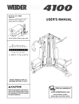
WEIGHT SYSTEM EXERCISER
User's Manual
Serial Number Decal (under seat)
• Assembly
• Adjustments
• Troubleshooting
• Part List and Drawing
_CAUTION
Patent Pending
Read all precautions and instructions in this manual before using
this equipment. Save this manual for future reference.
Sears, Roebuck
and Co., Hoffman Estates,
IL 60179
I
TABLE OF CONTENTS
IMPORTANT PRECAUTIONS .............................................................
BEFORE YOU BEGIN ...................................................................
ASSEMBLY ...........................................................................
ADJUSTMENTS .......................................................................
WEIGHT RESISTANCE CHART ...........................................................
TROUBLESHOOTING ..................................................................
CABLE DIAGRAMS ....................................................................
EXERCISE GUIDELINES ................................................................
ORDERING REPLACEMENT PARTS ................................................
FULL 90-DAY WARRANTY .......................................................
3
4
5
13
15
16
17
18
Back Cover
Back Cover
Note: A PART IDENTIFICATION CHART and a PART LIST/EXPLODED DRAWING are attached to the center of
this manual. Remove the PART IDENTIFICATION CHART and PART LIST/EXPLODED DRAWING before beginning assembly.
2
IMPORTANT
PRECAUTIONS
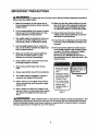
WARNING:
To reduce the risk of serious injury, read the following important precautions
before using the weight system.
1.
Read all instructions in this manual and in
the accompanying literature before using the
weight system,
2.
It is the responsibility of the owner to ensure
that all users of the weight system are adequately informed of all precautions.
3.
4.
12. Make sure that the cables remain on the pulleys st all times. If the cables bind while you
are exercising, stop immediately and make
sure that the cables are on all of the pulleys.
13. Always disconnect the lat bar from the
weight system when p_rmlng
an exercise
that does not use the lat bar.
The weight system is intended for home use
only. Do not use the weight system in any
commercial, rental, or institutional setting.
14. If you feel pain or dizziness at any time while
exercising, stop immediately and begin cooling down.
Use the weight system only on a level surface. Cover the floor beneath the weight system to protect the floor.
5.
Make sure all parts are properly tightened
each time the weight system is used.
Replace any worn parts immediately.
6.
Keep children under 12 and pets away from
the weight system at all times.
7.
Keep hands and feet away from moving
parts.
8.
Always wear athletic shoes for foot protection.
9.
The weight system is designed to support a
maximum user weight of 300 pounds.
15. The decals shown below have been placed
on the weight system in the locations shown
on page 4. If a decal is missing or illegible,
call our toll-free Customer Service
Department at 1-800-999-3756
and order a
free replacement
decal. Apply the decal in the
location shown,
• Misuseof this product
may result In serious
njury.
• Readuser's manual
and follow all warnings
and operatinginstructions priorto use.
• Do not allowchildren
on or around machine.
• Replace label if
damaged,illegible,or
removea.
10. Always stand on a foot plate when performing an exercise that could cause the weight
system to tip.
11. Never release the press arm, butterfly arms,
leg lever, lat bar, or nylon strap while weights
are raised. The weights will fell with great
force.
w
Decal 2
•
Decal 1
.q WARNING:
Before beginning this or any exercise program, consult your physician. This
is especially important for persons over the age of 35 or persons with ;)re-existing health problems.
Read all instructions before using, Sears assumes no responsibility for personal injury or property
damage sustained by or through the use of this product.
3
BEFORE YOU BEGIN
Thank you for selecting the versatile WELDER®PRO
2250 weight system. The weight system offers an
impressive array of weight stationsdesigned to develop every major muscle group of the body. Whether
your goal is to tone your body, build dramatic muscle
size and strength, or improve your cardiovascular system, the weight system will help you to achieve the
specificresults you want.
reading this manual, call 1-800-4-MY-HOME ®
(1-800-469-4663). To help us assist you, please note
the product model number and sedal number before
calling. The model number is 831.159300. The serial
number can be found on a decal attached to the
weight system (see the front cover of this manual for
the locationof the decal).
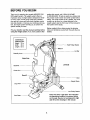
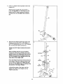
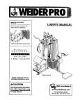
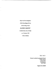
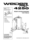
Before reading further, please review the drawing
below and familiarize yourself with the parts that are
labeled.
For your benefit, read this manual carefully before
using the weight system, If you have questions after
ASSEMBLED
DIMENSIONS:
Height: 76 in.
Width: 38 in.
Length: 53 in.
High Pulley Station
Let Bar
Butterfly Arms
Right Side
Left Side
Backrest
Press Arm
Decal 2
Seat
Weight Stack
Leg Lever
Low Pulley Station
Note: The terms "right side" and "left side"
are determined relative to a person sitting
on the seat; they do not correspond to right
and left on the drawings in the manual.
Foot Plate
4
ASSEMBLY
• For help identifyingsmall parts, use the PART
IDENTIFICATION CHART at the center of this
manual.
Make Things Easier for Yourself
Everything in this manual is designedto ensure
that the weight system can be assembled successfullyby anyone. However, it is importantto
realize that the weight system has many parts
aM that the assembly process will take time.
Most people find that by setting aside plenty of
time, assembly will go smoothly.
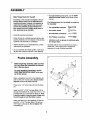
The following tools (not included) are required
for assembly:
• Two adjustable wrenches
• One rubber mallet
• One standard screwdriver
• Assembly requires two people.
• One Phillips screwdriver
• Place all parts in a cleared area and remove the
packing materials. Do not dispose of the packing
materials until assembly is completed.
• Lubricant, such as grease or petroleum jelly,
and soapy water.
• Tighten all parts as you assemble them, unless
instructed to do otherwise.
Assembly will be more convenient if you have a
socket set, a set of open-end or closed-end
wrenches, or a set of ratchet wrenches.
• As you assemble the weight system, make sure
all parts are oriented as shown in the drawings.
1.
Before beginning assembly, make sure that
you have read and understand the information inthe box above.
4
79
For help identifying small parts, use the
PART IDENTIFICATION CHART in the cantar of this manual
Attach a Stabilizer Foot (51) to the Stabilizer (5)
with two #8 x 3/4" Screws (56). Attach another
Stabilizer Foot in the same manner.
q
Press two 2" x 3" Inner Caps (79) into the Base
(4).
51
5
51
Insert two 5/16" x 2 3/4" Carriage Bolts (14) up
through the Stabilizer (5). Insert two 5/16" x 2 1/2"
Carriage Bolts (1) up through the Base (4). Note:
It may be helpful to place a piece of tape over
the bolt heads to hold the Bolts in place.
14
56
Attach the Base (4) to the Stabilizer (5) with the
two 5/16" x 2 3/4" Carriage Bolts (14) and two
5/16" Nylon Locknuts (3). Do not tighten the
Locknuts yet.
5
2.
Press a 1" Square Inner Cap (65) into the Front
Upright (42).
Slide the Front Upright (42) onto the 5/16" x
2 1/2" Carriage Bolts (1) in the Base (4). Hand
tighten two 5/16" Nylon Locknuts (3) onto the
Carriage Bolts. Do not tighten the Locknuts
yet.
65
4
1
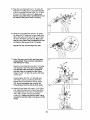
3. Attach the two Weight Guides (62) inside of the
Stabilizer (5) with two 5/16" x 2 3/4" Bolts (11),
two 5/16" Washers (8), two 1/2" x 17/32" Spacers
(61), and two 5/16" Nylon Locknuts (3).
Tighten the 5116" Nylon Locknuts
step 1.
(3) used in
Slide two Weight Bumpers (19) onto Weight
Guides (62). Stack the six Weights (25) on the
Weight Bumpers (19). Make sure that all of the
Weights are turned so the large pin grooves
are on the bottom of the Weights and on the
same side of the weight stack,
63
Pin
Groove
Press the Weight Tube Bumper (64) into the end
of the Weight Tube (63). Insert the Weight Tube
into the stack of Weights (25). Make sure that
the pins on the Weight Tube are resting in the
pin grooves in the upper Weight,
_64
25
Pin
Groov
Lubricate the insides of the holes in the Top
Weight (76). Slide the Top Weight onto the
Weight Guides (62).
61
-5
3
6
Press two 2" Square Inner Caps (27) into the indicated ends of the Top Frame (55). Press two
1 3/4" Square Inner Caps (44) into the ends of
the crossbar on the Top Frame. Press two Round
Inner Caps (78) into the top of the crossbar.
4,
4
44
27
5.
Attach the Top Frame (55) to the Front Upright
(42) with two 5/16" x 2 3/4" Bolts(11), two 5/16"
Washers (8), and two 5/16" Nylon Locknuts (3).
Crossbar
78
44
5
Attach the upper ends of the Weight Guides (62)
to the Top Frame (55) with a 5/16" x 6" Bolt (60)
and a 5/16" Nylon Locknut (3).
55
3
Tighten the 5/16" Nylon Locknuts (3) used in
steps 2 and 5.
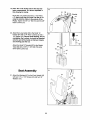
8.
6O
Press two 1" x 7/8" Plastic Bushings (75) onto the
welded spacers on the Press Frame (17). Slide
the Press Frame into place on the Base (4) as
shown. Note: This will be a tight fit. The Plastic
Bushings should fit onto each end of the indicated tube in the Base,
Lubricatethe 3/8" x 8" Bolt (59) with grease.
Attach the Press Frame (17) to the Base (4) with
the Bolt and a 3/8" Nylon Locknut (21). Do not
overtighten the Locknut; the Press Frame
must be able to pivot easily,
7,
_Tube
7
Press a 2" Round Inner Cap (33) into the top of
the Right Press Arm (46). Press two 1" Round
Inner Caps (49) into the handle on the Press Arm.
Attach the Right Press Arm (46) to the indicated
side of the Press Frame (17) with two 3/8" x
2 3/4" Bolts (22) and two 3/8" Nylon Locknuts
(21).
Assemble the other Press Arm (73) in the
same manner.
21
7
8.
Identify the RightArm (48) and the Left Arm (47)
by the position of the welded bracket on each Arm.
8
Press a 2" Round Inner Cap (33) into the lower
end of the Left Arm (47). Wet the end of the Arm
with soapy water and slide a 10" Pad (45) onto it.
Make sure the 1 1/8" x 2 1/2" Plastic Bushing (74)
is in the Arm.
/-_xle
Lubricate both axles on the Top Frame (55). Have
another person slide the Left Arm (47) onto the
left axle on the Top Frame. Note; Be careful not
to confuse the Right Arm (48) with the Left
Arm. Make sure that the upper end of the Left
Arm is behind the indicated bracket on the
Top Frame.
69_ '
.4
71
L
__
Set two 1" Retainers (69) on top of a 1" Round
Cover Cap (70). Make sure that the teeth on the
Retainers bend toward the Cover Cap, as
shown in the inset drawing. Tap the Retainers
and Cap onto the Left axle on the Top Frame (55).
Attach the Right Arm (48) in the same manner,
....
9.
J
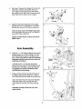
Cable Assembly
During steps 9 through 20, see the CABLE
DIAGRAMS on page 17 of this manual to verify
proper cable routing.
15
Locate the Short Cable (58). Lay the Cable in
the bracket on the Base (4) and under the Press
Frame (17). Attach a 3 1/2" Pulley (15) to the
bracket with a 3/8" x 2" Bolt (12) and a 3/8" Nylon
Locknut (21). Make sure that the end of the
Cable with the ball is on the indicated side of
the bracket,
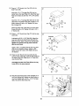
10. Route the Short Cable (58) under a 3 1/2" Pulley
(t5) Attach the Pulley and a Cable Trap (66) to
the lower hole in the Front Upright (42) with a 3/8"
x 3 3/4" Bolt (71), a 3/8" Washer (9), and a 3/8"
Nylon Locknut (21). Make sure that the Cable
Trap is turned to hold the Cable in the groove
of the Pulley.
58 21.
4
10
4221
71
58
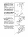
11. Note: The 3 1/2" Pulley (15) in this step has
been preassembled. It is shown exploded in
this drawing for clarity.
11
\
Route the Short Cable (58) around the 3 1/2"
Pulley (15). Make sure that the Cable Trap (66)
is turned to hold the Cable in the groove of
the Pulley. Tighten the 3/8" x 3 1/2" Bolt (16), the
3/8" Washer (9), and the 318"Nylon Locknut(21).
16
12. Route the Short Cable (58) under a 3 1/2" Pulley
(15). Attach the Pulley and a Cable Trap (66) to
the upper hole in the Front Upright (42) with a
3/8" x 3 3/4" Bolt (71), a 3/8" Washer (9), and a
3/8" Nylon Locknut (21). Make sure that the
Cable Trap is turned to hold the Cable in the
groove of the Pulley.
12
21
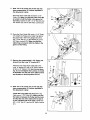
13. Remove the preassembled 3 1/2" Pulley (not
shown) from the Long "U"-bracket (57).
Attach the end of the Short Cable (58) to the
Long "U"-bracket (57) with a 1/4" Nylon Locknut
(2) and a 1/4" Washer (10). See the inset drawing. Do not overtighten the Locknut; it should
be threaded onto the end of the Cable so that
two threads are showing above the nut.
14. Note: The 3 112" Pulley (15) in this step has
been preassembled.
It is shown exploded in
this drawing for clarity.
14
Locate the Long Cable (23). Route the Long
Cable over a 3 1/2" Pulley (15). Make sure that
the Cable is between the Pulley and the hook
and that the end of the Cable with the ball is
on the indicated side of the hook. Tighten the
3/8" x 3 3/4" Bolt (71) and the 3/8" Nylon Locknut
(21).
9
42
"
9
•
15. Wrap the Long Cable (23) over a =V"-pulley (6).
Attach the "V"opulleyand a Long Cable Trap (50)
to the Front Upright (42) with a 3/8" x 2 1/2" Bolt
(7) and a 3/8" Nylon Locknut (21). Make sure
that the Long Cable Trap is positioned to hold
the Cable in the groove of the "V"-pulley.
15
6
7
42
5O
23
"21
16. Route the Long Cable (23) around a "V"-pulley
(6). Attach the "V"-pulley and a Long Cable Trap
(50) to the Left Arm (47) with a 3/8" x 2 1/2" Bolt
(7) and a 3/8" Nylon Locknuts (21). Make sure
that the Long Cable Trap is positioned to hold
the Cable in the groove of the "V"-pulley.
16
Repeat this step with the Right Arm (48).
48
17. Note: The parts used in this step have been
preassembled.
They are shown exploded in
this drawing for clarity.
Route the Long Cable (23) over the 3 1/2" Pulley
(15) attached to the Pulley Bracket (20). Make
sure that the Cable Trap (66) is oriented to
hold the Cable in the groove of the Pulley.
Tightenthe 3/8" x 2" Bolt (12) and the 3/8" Nylon
Locknut (21).
Properly tighten the 5/16" x 5" Bolt (68) and a
5116"Nylon Locknut (3) attaching the Pulley
Bracket (20) to the bracket on the Top Frame
(55). Do not overtighten the Locknut; the
Pulley Bracket must be able to pivot easily.
18
18. Wrap the Long Cable (23) under a 3 1/2" Pulley
(15). Attach the Pulley and a Cable Trap (66) to
the indicated hole in the Long "U"-bracket (57)
with a 3/8" x 2" Bolt (12) and a 3/8" Nylon
Locknut (21). Make sure that the Cable Trap is
oriented to hold the Cable in the groove of the
Pulley,
12
10
21
19. Note: The 3 1/2" Pulley (15) in this step has
been preassembled. It is shown exploded in
this drawing for clarity.
19
21
55
Bracket
Route the Long Cable (23) over a 3 1/2" Pulley
(15). Make sure that the Cable Trap (66) is oriented to hold the Cable in the groove of the
Pulley. Tighten the 3/8" x 2" Bolt (12) and the 3/8"
Nylon Locknut (21).
12
20. Attach the Long Cable (23) to the Small "U"bracket (67) with a 1/4" Nylon Locknut (2) and a
1/4" Washer (10). See the inset drawing. Do not
overtighten the Locknut; it should be threaded
onto the end of the Cable so that two threads
are showing past the nut,
iI
2O
23_
Attach the Small "U"-bracket (67) to the Weight
Tube (63) with a 5/16" x 1 3/4" Bolt (72) and a
5/16" Nylon Locknut (3).
J
Seat iAssembly
_2
_67
3
o!i
21
41
21. Attach the Backrest (41) to the Front Upright (42)
with two 1/4" x 2 1/2" Screws (43) and two 1/4"
Washers (10).
10
- 42
43
11
22. Press a 1 1/2" Square Inner Cap (32) into the
Seat Frame (36).
22
13
Insert the 1/4" x 2" Carriage Bolt (38) into the
center hole in the Seat Plate (37). Attach the Seat
Plate to the Seat (13) with two 1/4" x 3/4" Screws
(18).
Insert the 1/4" x 2" Carriage Bolt (38) into the indicated hole in the Seat Frame (36). Tighten a 1/4"
Nylon Locknut (2) with a 1/4" Washer (10) onto
the Carriage Bolt.
Attach the other end of the Seat (13) to the Seat
Frame (36) with a 1/4" Washer (10) and a 1/4" x
2" Screw (24).
23. Press a 1 1/2" Round Inner Cap (77) into the Leg
Lever (29).
23
Lubricate
Lubricate the 6/16" x 2 1/2" Bolt (80). Attach the
Leg Lever (29) to the Seat Frame (36) with the
Bolt and a 5/16" Nylon Locknut (3). Do not overtighten the Locknut; the Leg Lever must be
able to pivot freely.
36
Insert a 3/8" x 2" Eyebolt (35) into the Leg Lever
(29) from the direction shown. Tighten a 3/8"
Nylon Locknut (21) and a 3/8" Washer (9) onto
the Eyebolt.
24. Press two 3/4" Round Inner Cap (34) into the
ends of a Pad Tube (28). Insert the Pad Tube into
the Seat Frame (36). Slide two 5 1/2" Pads (30)
onto the Pad Tube.
24
30
Assemble the other Pad Tube (28) to the Leg
Lever (29) in the same manner.
28
25. Rest the Seat Frame (36) on the indicated pin in
the Front Upright (42). Attach the Seat Frame to
the Front Upright with a 5/16" x 2 3/4" Carriage
Bolt (14) and the Seat Knob (40).
25
12
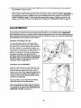
26. Make sure that all parts have been properly tightened. The use of the remaining parts win be explained in
ADJUSTMENTS, beginning below.
Before using the weight system, pull each cable a few times to make sure that the cables move smoothly
over the pulleys. If one of the cables does not move smoothly, find and correct the problem. IMPORTANT:
the cables are not properly installed, they may be damaged when heavy weight is used. See the
CABLE DIAGRAM on page 17 of this manual for proper cable routing. If there is any slack in the
cables, you will need to remove it by tightening the cables; see TROUBLESHOOTING
on page 16.
If
ADJUSTMENTS
The instructions below describe how each part of the weight system can be adjusted. See the exercise guide
accompanying
this manual to see how the weight system should be set up for each exercise. IMPORTANT:
When attaching the lat bar or handle, make sure that the attachments are in the correct starting position
for the exercise to be performed. If there is any slack in the cables or chain as an exercise is performed,
the effectiveness
of the exercise will be reduced.
CHANGING THE WEIGHT SETTING
To change the weight setting of the weight stack,
insert the Weight Pin (26) under the desired Weight
(25). Make sure to insert the Weight Pin until the bent
end of the Weight Pin is touching the Weights, and
turn the bent end downward. The weight setting of the
weight stack can be changed from 6 pounds to 81
pounds, in increments of 12.5 pounds. Note: Due to
the cables and pulleys, the actual amount of
resistance at each exercise station may vary from
the weight setting. Use the WEIGHT RESISTANCE
CHART on page 15 to find the actual amount of
resistance at each weight station.
125
ATTACHING THE ACCESSORIES
Attach the Lat Bar (54) to the Long Cable (23) with a
Cable Clip (53). For some exercises, the Chain (52)
should be attached between the Lat Bar and the
Cable with two Cable Clips. Adjust the length of the
Chain between the Lat Bar and the Cable so the
Lat Bar is in the correct starting position for the
exercise to be performed.
53
The accessories can be attached to the Short
Cable (not shown) in the same manner,
Note: The seat frame
must be removed
from the
front upright before the Short Cable (not shown)
is used with an accessory. (See ATI'ACHING AND
REMOVING THE SEAT, on page 14.)
13
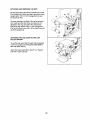
ATTACHING AND REMOVING THE SEAT
Set the Seat Frame (36) onto the indicated pin on the
Front Upright (42). Attach the Seat Frame to the Front
Upright with a 5/16" x 2 314"Carriage Bolt (14) and
the Seat Knob (40).
13
For some exercises, the Seat (13) must be removed.
First, make sure that the Chain (not shown) is not
attached to the Leg Lever (29). Next, remove the
Seat Knob (40) and the 5/16" x 2 3/4" Carriage Bolt
(14) from the Seat Frame (36). Lift the Seat Frame off
the Front Upright (42).
ATTACHING THE LEG LEVER TO THE LOW
PULLEY STATION
To use the Leg Lever (29), the seat must be attached
to the front upright (see ATTACHING AND REMOVING THE SEAT, above).
2935
Attach the Short Cable (68) to the 3/8" x 2" Eyebolt
(35) with a Cable Clip (53).
58
14
WEIGHT
RESISTANCE
CHART
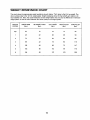
This chart shows the approximate weight resistance at each station. "Top" refers to the 6 lb. top weight. The
other numbers refer to the 12.5 lb. weight plates. Weight resistance shown for the butterfly arm station is for
each butterfly arm. Note: The actual resistance at each weight station may vary due to differences in individual
weight plates, as well as friction between the cables, pulleys, and weight guides.
WEIGHT
PLATES
PRESS ARM
(Ibs.)
BUTTERFLYARM
(Ibs.)
LEG LEVER
(Ibs.)
HIGH PULLEY
(Ibs.)
LOW PULLEY
(Ibs.)
Top
20
10
15
14
24
1
45
22
36
28
54
2
70
33
54
44
82
3
99
42
75
60
115
4
128
48
96
72
147
5
153
60
115
90
175
6
184
69
137
103
209
15
TROUBLESHOOTING
Inspectand tighten all parts each time the weight system is used. Replace any wom parts immediately. The
weight system can be cleaned using a damp cloth and mild non-abrasive detergent. Do not use solvents.
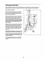
TIGHTENING THE CABLES
Woven cable, the type of cable used on the weight
system, can stretch slightly when it is first used. If
there is slack in the cables before resistance is felt,
the cables should be tightened.
/
Slack can be removed by moving the 3 1/2" Pulley
(15) to the lower hole in the Long "U"-bracket(57).
Remove the 3/8" Nylon Locknut (21) and the 3/8" x 2"
Bolt (12) from the Cable Trap (66), Pulley, and "U"bracket. Re-attach the Pulley and Cable Trap. Make
sure that the Cable Trap is positioned to hold the
Cable in place, and that the Cable and Pulley
move smoothly.
Additional slack can be removed from the cables by
tightening the 1/4" Nylon Locknuts (2) at the end of
the Long Cable (23) and at the end of the Short
Cable (58). To do this you may need to remove the
Small "U'-bracket (67) from the Weight Tube (63) or
remove the 3 112"Pulley (15) from the Long "U"bracket (57).
Make sure that the cables are not too tight, or the
Top Weight (76) will be lifted off the weight stack.
Note: If a cable tends to slip off the pulleys often,
the cable may have become twisted. Remove the
cable and re-install it.
If the cables need to be replaced, see ORDERING
REPLACEMENT PARTS on the back cover of this
manual.
16
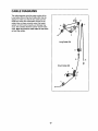
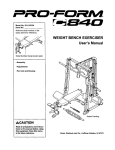
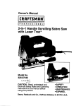
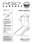
CABLE DIAGRAMS
The cable diagrams show the proper routing of the
Long Cable (23) and the Short Cable (58). Use the
diagram to make sure that the two cables and the
cable traps have been assembled correctly.If the
cables have not been correctly routed,the weight
system will not functionproperly and damage may
occur. The numbers show the correct route for each
cable. Make sure that the cable traps do not touch
or bind the cables.
-7
3
Long Cable (23)
6
_8
Short Cable (58)
3
17
EXERCISE
GUIDELINES
THE FOUR BASIC TYPES OF WORKOUTS
PERSONALIZING YOUR EXERCISE PROGRAM
MUSCLE BUILDING
To increase the size and strength of your muscles,
push them close to their maximum capacity.Your muscles will continuallyadapt and grow as you progressively increase the intensityof your exercise. You can
adjust the intensity level of an individual exercise in
two ways:
• by changing the amount of resistance used
• by changing the number of repetitionsor sets performed. (A "repetition" is one complete cycle of an
exercise, such as one sit-up. A "set" is a series of
repetitions.)
Determining the exact length of time for each workout,
as well as the number of repetitions or sets completed,
is an individual matter. It is important to avoid overdoing it dudng the first few months of your exercise program. You should progress at your own pace and be
sensitive to your body's signals. If you experience pain
or dizziness at any time while exercising, stop immediately and begin cooling down. Find out what is wrong
before continuing. Remember that adequate rest and a
proper diet are important factors in any exercise program.
WARMING UP
The proper amount of resistance for each exercise
depends upon the individual user. You must gauge
your limits and select the amount of resistance that is
right for you. Begin with 3 sets of 8 repetitions for each
exercise you perform. Rest for 3 minutes after each
set. When you can complete 3 sets of 12 repetitions
without difficulty, increase the amount of resistance.
Begin each workout with 5 to 10 minutes of stretching
and light exercise to warm up. Warming up prepares
your body for more strenuous exercise by increasing
circulation, raising your body temperature and delivering more oxygen to your muscles.
WORKING
TONING
You can tone your muscles by pushing them to a moderate percentage of their capacity.Select a moderate
amount of resistance and increase the number of repetitions in each set. Complete as many sets of 15 to
20 repetitionsas possiblewithout discomfort. Rest for
1 minute after each set. Work your muscles by completing more sets rather than by using high amounts of
resistance.
WEIGHT LOSS
To lose weight, use a low amount of resistance and
increase the number of repetitions in each set.
Exercise for 20 to 30 minutes, resting for a maximum
of 30 seconds between sets.
CROSS TRAINING
Cross training is an efficient way to get a complete and
well-balanced fitness program. An example of a balanced program is:
• Plan strength training workouts on Monday,
Wednesday, and Friday.
• Plan 20 to 30 minutes of aerobic exercise, such as
runningon a treadmill or riding on an ellipticalor
exercise bike, on Tuesday and Thursday.
• Rest from both strength training and aerobic exercise
for at least one full day each week to give your body
time to regenerate.
The combination of strength training and aerobic exercise will reshape and strengthen your body, plus develop your heart and lungs.
OUT
Each workout should include 6 to 10 different exercises. Select exercises for every major muscle group,
emphasizing areas that you want to develop most. To
give balance and variety to your workouts, vary the
exercises from session to session.
Schedule your workoutsfor the time of day when your
energy level is the highest. Each workout should be
followed by at least one day of rest. Once you find the
schedule that is right for you, stick with it.
EXERCISE FORM
Maintaining proper form is an essential part of an
effective exercise program. This requires moving
through the full range of motion for each exercise, and
moving only the appropriate parts of the body.
Exercising in an uncontrolled manner will leave you
feeling exhausted. On the exercise guide accompanying this manual you will find photographs showing the
correct form for several exercises, and a list of the
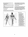
muscles affected. See the muscle chart on the next
page to find the names of the muscles.
The repetitions in each set should be performed
smoothly and without pausing. The exertion stage of
each repetition should last about half as long as the
return stage. Proper breathing is important. Exhale
during the exertion stage of each repetition and inhale
during the return stroke. Never hold your breath.
18
Rest for a short period of time after each set. The
ideal resting periods are:
• Rest for three minutes after each set for a muscle
building workout.
• Rest for one minute after each set for a toning workout.
• Rest for 30 seconds after each set for a weight loss
workout.
Plan to spend the first couple of weeks familiarizing
yourself with the equipment and learning the proper
form for each exercise.
COOLING
DOWN
slowly as you stretch and do not bounce. Ease into
each stretch gradually and go only as far as you can
without strain. Stretching at the end of each workout
is an effective way to increase flexibility.
STAYING
MOTIVATED
For motivation, keep a record of each workout.List the
date, the exercises performed, the resistance used,
and the numbers of sets and repetitions completed.
Record your weight and key body measurements at
the end of every month. Remember, the key to achieving the greatest results is to make exercise a regular
and enjoyable part of your everyday life.
End each workout with 5 to 10 minutes of stretching.
Include stretches for both your arms and legs. Move
MUSCLE
s
r
v
w
t9
A.
B.
C.
D.
E.
F.
G.
H.
I.
J.
K.
L.
M.
N.
O.
P.
Q.
R.
S.
T.
U.
V.
W.
X.
CHART
Stemomastoid (neck)
Pectoralis Major (chest)
Biceps (front of arm)
Obliques (waist)
Brachioradials (forearm)
Hip Flexors (upper thigh)
Abductor (outer thigh)
Quadriceps (front of thigh)
Sertorius (frontofthigh)
Tibialis Antedor (front of calf)
Soleus (front of calf)
Anterior Deltoid (shoulder)
Rectus Abdominus (stomach)
Adductor (inner thigh)
Trapezius (upper back)
Rhomboideus (upper back)
Posterior Deltoid (shoulder)
Triceps (back of arm)
Latissimus Dorsi (mid back)
Spinae Erectors (lower back)
Gluteus Medius (hip)
Gluteus Maximus (buttocks)
Hamstring (back of leg)
Gastrocnemius (back of calf)
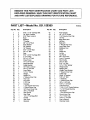
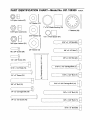
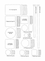
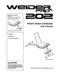
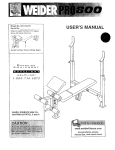
REMOVE
THIS PART IDENTIFICATION
CHART AND PART LIST/
EXPLODED DRAWING, SAVE THIS PART IDENTIFICATION CHART
AND PART LIST/EXPLODED DRAWING FOR FUTURE REFERENCE.
PART LIST--Model
Key No. Qty.
1
2
3
4
5
6
7
8
9
10
11
12
13
14
15
16
17
18
19
20
21
22
23
24
25
26
27
28
29
30
31
32
33
34
35
36
37
38
39
40
41
2
3
12
1
1
3
3
4
4
6
4
4
1
3
8
1
1
2
2
1
17
4
1
1
6
1
2
2
1
4
2
1
4
4
1
1
1
1
1
1
1
No. 831.159300
Description
5/16" x 2 1/2" Carriage Bolt
1/4" Nylon Locknut
5/16" Nylon Locknut
Base
Stabilizer
"V"-pulley
3/8" x 2 1/2" Bolt
5/16" Washer
3/8" Washer
1/4" Washer
5/16" x 2 3/4" Bolt
3/8" x 2" Bolt
Seat
5/16" x 2 3/4" Carriage Bolt
3 112"Pulley
3/8" x 3112" Bolt
Press Frame
1/4" x 3/4" Screw
Weight Bumper
Pulley Bracket
3/8" Nylon Locknut
3/8" x 2 3/4" Bolt
Long Cable
1/4" x 2" Screw
Weight
Weight Pin
2" Square Inner Cap
Pad Tube
Leg Lever
5 112"Pad
Handgrip
1 1/2" Square Inner Cap
2" Round Inner Cap
3/4" Round Inner Cap
3/8" x 2" Eyebolt
Seat Frame
Seat Plate
I/4" x 2" Carriage Bolt
Handle
Seat Knob
Backrest
RO903A
Key No. Qty.
42
43
44
45
46
47
48
49
50
51
52
53
54
55
56
57
58
59
60
61
62
63
64
65
66
67
68
69
70
71
72
73
74
75
76
77
78
79
80
#
#
1
2
2
2
1
1
1
4
3
2
1
3
1
1
4
1
1
1
1
2
2
1
I
1
5
1
1
4
2
3
1
1
2
2
1
1
2
2
1
1
1
Description
Front Upright
1/4" x 2 1/2" Screw
1 3/4" Square Inner Cap
10" Pad
Right Press Arm
Left Arm
Right Arm
1" Round Inner Cap
Long Cable Trap
Stabilizer Foot
Chain
Cable Clip
Lat Bar
Top Frame
#8 x 3/4" Screw
Long "U"-bracket
Short Cable
3/8" x 8" Bolt
5/16" x 6" Bolt
1/2" x 17/32" Spacer
Weight Guide
Weight Tube
Weight Tube Bumper
1"Square Inner Cap
Cable Trap
Small "U"-bracket
5/16" x 5" Bolt
1" Retainer
1" Round Cover Cap
3/8" x 3 3/4" Bolt
5/16" x 1 3/4" Bolt
Left Press Arm
1 1/8" x 2 1/2" Plastic Bushing
1" x 7/8" Plastic Bushing
Top Weight
1 1/2" Round Inner Cap
Round Inner Cap
2" x 3" Inner Cap
5/16" x 2 1/2" Bolt
User's Manual
Exercise Guide
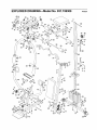
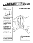
EXPLODED
DRAWING--Model
44
No. 831.159300
RO9O3A
27
3
12
30
_38
,:
-""
i
15
23
,: 50
15
66
30
30
34
30
57
34
10
_58
7O
_62
6
:,,
72
_L- 2
10
21
66
15 22
-25
11
4
79
3
21
51
59
_71
5
14
PART IDENTIFICATION
CHART--Model
No. 831.159300
Ro903,,,,
1/4" Nylon Locknut (2)
1/4" Washer (10)
1" x 7/8" Plastic Bushing (75)
1" Retainer (69)
5/16" Nylon Locknut (3)
5/16" Washer (8)
1/2" x 17132" Spacer
(61)
5/16" x 2 !/2" Bolt (80) _]
3/8" Nylon Locknut (21)
3/8" Washer (_
3/8" x 2 1/2" Bolt (7)
#8 x 3/4" Screw (56)
==
1/4" x 3/4" Screw (18)
_
x
r_
318" x 2 3/4" Bolt (22) _
"13
5/16" x 2 1/2" Carriage Bolt (1) [_
5/16" x 1 3/4" Bolt (72)
D
1/4" x 2" Screw (24)
(3
13o
I
(.Q
6/16"
x23/4"
Bolt(11)
/,
5/16" x 2 3/4" Carriage
3/8" x 2" Bolt (12)
(
1/4" x 2" Carriage
Bolt (14)
f
Bolt (38)
1/4" x 2 1/2" Screw (43)
L
3/8" x 3 1/2" Bolt (16)
3/8" x 3 3/4" Bolt (71)
5/16"x
5" Bolt (68)
m
m
E
__
o
{:{3
2" x 3" Inner Cap (79)
X
¢O
--
m
1 1/2" Square
Inner Cap (32)
2" Square Inner Cap (27)
1" Round Cover Cap (70)
3/4" Round Inner Cap (:34)
1 3/4" Square
Inner Cap (44)
1 1/2" Round Inner Cap (77)
Round Inner Cap (78)
1" Round Inner Cap (49)
1" Square Inner Cap (65)
Your Home
For repair - in your home - of all major brand appliances, lawn and garden equipment,
or heating and cooling systems, no matter who made it, no matter who sold it!
For the replacement
parts, accessories, and user's manuals that you need to do-it-yourself.
For Sears professional installation of home appliances
and items like garage door openers and water heaters.
1-800-4-MY-HOM
E®
Anytime, day or night
(U,S.A. and Canada)
www, sears.ca
(1-800-469-4663)
www.seara.com
OurHome
iiiiiii!
For repair of carry-in products like vacuums, lawn equipment,
and electronics, call or go on-line for the location of your nearest
Sears Parts and Repair Center.
;'_i;
.......
....
1-800-488-1222
Anytime, day or night (U.S.A. only)
www.sears.com
!iiiiiii
To purchase a protection agreement (U...SA)
or maintenance agreement (C anada ) on a product servic ed by S ears:
1-800-827-6655
(U.S.A.)
1-800-361-6665
....
(Canada)
Para pedir servicio de reparacidn a domicilio y para ordenar piezas:
i ii!iiii!
i;
......
1 8_-SU
HOGAR s_ {1-888-784-6427)
......
?
SEARS
Registered Trademark / TUTrademark / s_ Service Mark of Sears, Roebuck and Co.
® MarC_ Registrada / TM Marea de Fabrica / SMM;_rcade Se P,'iciode Sears, Roebuck and Co.
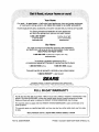
FULL 90-DAY WARRANTY
For 90 days from the date of purchase, if failure occurs due to defect in material or workmanship in this
WEIGHT SYSTEM EXERCISER, contact the nearest Sears Service Center throughout the United
States and Sears will repair or replace the WEIGHT SYSTEM EXERCISER, free of charge.
This warranty does not apply when the WEIGHT SYSTEM EXERCISER is used commercially or for
rental purposes.
This warranty gives you specific legal rights, and you may also have other rights which vary from state
to state.
Sears, Roebuck
Part No. 200008 R0903A
and Co., Dept 817WA,
Hoffman
Estates,
IL 60179
Printed in Canada © 2003 ICON Health & Fitness, Inc.