1
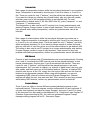
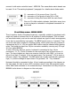
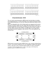
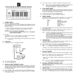
USER MANUAL
for
MIDI128
rev.F
– MIDI keyboard controller
firmware version 2.x
www.midi-hardware.com
Roman Sowa 2009
Overview
This model is the heart of average scale consoles with multiple keyboards and
various functions. By itself it scans 128 contacts and generates appropriate MIDI
notes. It cannot translate the velocity (or dynamics) of the hit key into MIDI, but
this parameter can be set with a knob or pedal. If 128 keys (in 2 keyboards) is not
enough, you can connect 2 expanders that take care of additional keyboards. There
are several expander sizes available: for 32, 64 and 128 keys. This way, up to 6
keyboards can be used, or 384 keys. In addition to the keyboards, there are 7
inputs for potentiometers to work like in typical MIDI knob box. Their functions are
user configurable to some extent.
Features
•
•
•
•
•
•
•
•
•
•
2 on-board inputs for 64-keys keyboards
expandable by 2 optional scanners, each for 32, 64 or 128 contacts
velocity of MIDI notes determined by a pot
independent transposition for all keyboards in steps of 1 semitone and 1 octave
MIDI channel set separately for each keyboard and each CC (potentiometer)
any MIDI Continuous Controller defined independently for each potentiometer
Program Change by 2 +/- buttons, separate count for each keyboard
MIDI activity indicator
all settings stored in non volatile memory, remain after power cycle
factory settings recall of default transposition, MIDI channels and CC types
Layout
J1
J2
J3
J4
J5
J6
J7
J8
–
–
–
–
–
–
–
–
first keyboard (8x8 diode matrix interface)
second keyboard (8x8 diode matrix interface)
scanner/expander input
MIDI cable connector
scanner/expander input
special functions connector
connector for potentiometers or control voltages
power supply
Power supply
Recommended power supply range is between 6 and 12V DC, and it must be
connected to the screw terminals (J8) as indicated in the drawing above.
Connecting power in reverse will not damage the board, but it works only while
proper polarity is maintained. It is possible to run this board even from lower
voltage, but its operation is not guaranteed then. Current consumption doesn't
exceed 3mA with 2 expanders connected and no potentiometers. If there are 20k
pots, current consumption will rise by 0.25mA per pot.
Connecting keyboards
Keyboard switches are connected to 2 keyboard interfaces
(J1 and J2) and with optional keyboard scanners, or in
another words - expander boards, which is described in
Expanders section later in this manual.
Two onboard 8x8 scanner drivers can be used if the
keyboard has “scanning diode matrix”, that's simple circuit,
made of diodes forming electric XY array of 8 rows and 8
columns. Usually all modern keyboards are equipped with it.
In fact it is integral part of the contacts board found beneath
the keys. Those kind of keyboards can work directly with
MIDI128 controller, as well as optional DMS-2K scanner.
Older keyboards, and especially those used in old analog
organs, usually don't have such a thing, so in order to use
8x8 scanner, you must solder the diodes to your contacts,
according to schematics on the right.
Table below shows scanner needed for different keyboards:
Keyboard type
MIDI128
DMS-2K
Independent switches, no
◊
connection to any circuitry
Switches organized in 8x8
●
matrix, with diodes
Switches organized in 8x8
◊
matrix, no diodes
Switches 5x12 and other
(Yamaha, Casio)
One common rail for all
switches
BBS
PEDSCAN
●
◊
‡
●
‡
◊
‡
●
● - can be used directly
◊ - with external diode matrix
‡ - some rewiring of original contacts circuit may be required
On the MIDI128 controller, as well as DMS-2K expander,
each 16-way connector covers one keyboard.
Schematic on the right side of this page shows
compatible diode matrix.
Connecting potentiometers
Pot inputs can be used as continuous controllers for things like volume, modulation
etc. Usually those inputs would be connected to potentiometers, but it's possible to
use them as analog inputs with range of 0..+5V. Applying voltage of 0V causes
MIDI128 to generate CC with lowest value, while +5V generates highest possible
value of assigned MIDI parameter. There are 8 available inputs, 7 of them user
configurable in terms of controller type and MIDI channel. Potentiometers are
connected to 1 smaller black connector (J7). 8th input (pin 10) is dedicated for
MIDI notes velocity setting. Below is schematic of potentiometers connections:
The pinout for J7 is as follows:
–
–
–
–
1 Vcc, connect to upper terminal of all 8 pots
2 GND, connect to lower terminal of all pots
3-9 CC inputs, connect wiper terminals of CC pots
10 velocity input, connect wiper of the pot controlling notes' velocity
If you don't use all 8 potentiometers, it is recommended to connect unused inputs
to VCC (pin 1 of J7). It's quite safe to leave them open, but in some cases it may
result in unwanted MIDI CC messages. The potentiometers must be linear taper
(non audio). Recommended resistance value is 10-50kohms.
Special functions
There can be numerous features ordered, but standard set is just transposition and
channel change. All of them are available on small 10-pin connector marked as J6
in the layout diagram. They are organized as follows:
2
GND
1
VCC
4
transpose +1
3
transpose -1
6
octave +1
5
octave -1
8
channel +1
7
channel -1
10
prog. ch. +1
9
prog. ch. -1
This is the look of the pins if the J6 was rotated left by 90 deg. from position shown
in the layout diagram. The numbers in this table correspond with wire number if
standard flat cable with IDC plug is used
Transposition
Each usage of transposition buttons shifts the last played keyboard in one semitone
steps. Transposition is achieved by shorting pins 2 and 4 for sharp, or 2 and 3 for
flat. There are inputs for only 2 “buttons”, and they affect last played keyboard. So
if you want to change e.g. starting key of pedal board, play any note with pedals,
and then press one of the transpose buttons to get desired shift. To reset
transposition to default state (C, 65.4Hz, MIDI note 36), press “transpose” +1 and
“transpose -1” simultaneously.
The transposition is also used to set CC number for a chosen potentiometer, and
starting Program Change number in case of split keyboard. There mustn't be any
keys pressed while setting transposition, neither any potentiometer cannot be
touched.
Octave
Each usage of octave buttons shifts the last played keyboard one octave up or
down. Octave transposition is achieved by shorting pins 2 and 6 for one octave up,
or 2 and 5 to for one octave down. There are inputs for only 2 “buttons”, and they
affect last played keyboard. So if you want to change octave of certain keyboard,
play any note with it, and then press one of the octave buttons to get desired shift.
The octave is also used to set CC number for a chosen potentiometer, and starting
Program Change number in case of split keyboard. There mustn't be any keys
pressed while setting transposition, neither any potentiometer cannot be touched.
MIDI Channel
Channel of each keyboard and CC/potentiometer can be set independently. Shorting
pins 2 and 8 increments the MIDI channel used by last played keyboard, or last
moved potentiometer. Shorting pins 2 and 9 decrements the channel. There are
inputs for only 2 “buttons”, and they affect last played keyboard or last used
potentiometer. So if you want to change e.g. channel of pedal board, play any note
with pedals, and then press one of the channel buttons. Likewise, to change MIDI
channel used by one of the CCs, simply turn the knob a little and use the channel
buttons to set appropriate channel. When using split keyboards, you can set
independent MIDI channel for Notes part and Program Change part. Channel
settings will affect the part, that was used last. There mustn't be any keys pressed
while setting MIDI channel, neither any potentiometer cannot be touched.
Program Change
Those 2 pins are utility to choose different presets/patches/programs in each
keyboard/channel. There are program counters independent for each keyboard. If
you play one keyboard and want to change Program, short pins 2 and 10 to jump
to the next one from last used for that keyboard. E.g. If last time it was Program 17
(Drawbar Organ according to GM), the next one generated Program Change
message setting program will be 18 - Percussive Organ.
Factory Settings Recall
At any time standard settings of transposition, MIDI channels and CC types can be
recalled. That happens when you simultaneously press 4 buttons: transpose +1,
transpose -1, octave +1, octave -1, or in another words, pins 3,4,5,6 shorted to
GND (pin 2). Factory settings are as follows:
– starting note in each keyboard is #36, that is C, 2 octaves below middle one.
– Channels 1, 2 are assigned to keyboards scanned by MIDI128 at connectors J1 &
J2, first expander connected to J5 has channels 3 & 4, second expander,
connected to J3 works with channels 5 & 6.
– all 7 potentiometers are working as Channel Volume (#7) in channels 1-7
Continuous Controllers
As a standard, all 7 CC pots are configured as Volume (CC #7) in channels
1,2,3,4,5,6,7. This is default setting, but can be altered by the user, using
transposition, octave and channel change buttons described in previous section. To
change CC to other parameter than Volume, turn the pot in question to tell the
controller board that this pot will be altered. Then use transposition (change by 1)
and octave (change by 12) buttons to change it into desired CC number. For
example to change from volume (CC#7) to Modulation (CC#1) you need to press
“transpose -1” 6 times. To change it again from Modulation, to e.g. Expression
(CC#11), press “octave +1” once – that turns into CC#13 - and then “transpose -1”
twice to have CC#11.
At any time you can go back to default setting for chosen pot by turning it a little
and then pressing simultaneously “transpose +1” and “transpose -1”. This will setup
this pot as Volume (CC #7).
MIDI channel of the specified potentiometer can be changed in the same way, by
turning the knob and using channel change buttons. Those settings are written in
internal nonvolatile memory and will remain after the board is powered up again
next time.
Velocity input
There is one special potentiometer input, at pin 10 of J7, that cannot be used as
CC, instead it's considered as velocity input for all notes generated by the MIDI128
board and associated expanders. Velocity data of MIDI note is the information
about the force or speed a key was hit. This board, as well as all
expanders/scanners, don't measure that force/speed, in another words, they are
not velocity sensitive. But to have at least something, you can use the velocity
potentiometer to alter velocity of the notes during playing to have some way of
expression.
Activity indicator
Small green LED on MIDI128 board flashes whenever any MIDI message is
generated by the board. It's easy to see if the board works and if MIDI messages
are generated only when you want them to. It should be shortly flashing whenever
any key on entire system is pressed or released, and while the potentiometers are
rotated. This indicator is not intended to be wired to the panel by soldering wires to
it. It's only there for troubleshooting aid during installation.
Expanders
MIDI128 controller board works only with 2 keyboards, but it can be expanded by 2
additional controllers. Depending on their size, the whole system can cover up to 6
keyboards or 384 keys over single MIDI socket. Currently there are 3 sizes
available: 32, 64 and 128 keys, the last one is also a dual diode matrix scanner and
has the 128 keys split into 2 keyboards. Type of the scanner needed is determined
by keyboard size and the way how switches are organized. Connection between
keyboard scanner and MIDI128 mainboard is always the same, regardless of the
type of scanner. MIDI settings of those keyboards can be changed by the user after
all connections are in place.
32-keys expander - PEDSCAN-X
Pedal board controller takes care of 32 keys. It's very
small board that can be fitted inside pedal board, and it
connects to the main board via supplied 4-wire cable
from J2 connector.
Switches must be organized in 4x8 diode matrix. Details
are shown in schematic below. numbers 1-12 at the right side of the schematic
must match the numbers on the PEDSCAN-X board diagram.
The groups of 8 switches with 1 common lead must be separate. In case
of keyboard with 1 common bus bar going through entire keyboard, you
have to cut the bar every 8th key.
128-keys expander - DMS-2K
For increased number of keys, you may use DMS-2K, adding another 128 inputs.
Layout is shown on next page. There are two 16-way connectors, that usually are
used to connect diode-matrixed keyboards. Smaller connector marked is used to
connect it with main controller board - MIDI128. The same diode matrix boards can
be used. Go to “Connecting keyboards” paragraph for details about diode matrix.
J1 – connector of 1st group of keys (1 to 64)
J2 – connector of 2nd group of keys (65 to 128)
J3 – connector linking this board with the main board
Close to J3 is little activity indicator, that blinks every time
a note is played or released in a keyboard connected to
this board
32 and 64 keys scanner - BBS64X, BBS32X
There's another family of keyboard scanners, especially suitable for keyboards with
single rod used as common bus for all switches in entire keyboard. This one does
not use diode matrix, and can be used with almost any type of switch arrangement,
it can also be controlled by logic gates. The BBSX boards come in 2 variants. They
can work with either positive or negative keying, which means that key pressed is
represented by 0V, or +5V, but proper BBS version must be selected when placing
order. The board can have less 16-pin connectors available, covering only 32 keys.
It's then called BBS32X.
In case of the big, 64-keys version, keyboard is connected to four 16-pin
connectors - J1, J2, J3 and J4 shown on the next page. Each of them covers 16
keys. The key contacts can have one common buss bar (with GND), or it can be
driven from logic IC outputs. 0V at an input means “key pressed”, +5V at input or
left open means “key released”. The BBS board can be also ordered with reversed
logic, i.e. positive voltage at input means “key pressed”, 0V - “key released”.
Keyboard should be connected to four 16-pin headers according to the diagram on
the next page. It's best to use 4 IDC connectors and 16-wire flat computer grade
cable. Each cable connects to 16 consecutive keys. Connection of all keys to pins in
BBS64X is also shown in diagram on the next page.
LAYOUT
64 keys chainable scanner - BBS-1K
This one has the same functionality as BBSX boards described above, but adds a
few interesting features. For basic functionality and connections description please
refer to BBS64X description, here are only outlined the differences between those 2
boards.
BBS-1K has daisy-chain input, which allows to pack more scanners into the system.
You can use 4 BBS-1K boards, but only 2 BBSX board with MIDI128. It also has a
bit different connector layout, but all 4 connectors for ribbon cable are the same. In
contrary to BBSX, this one comes always in 64-inputs version, there's no smaller
one. Each black connector covers 16 keys, and little sticker on the board shows
what range of inputs are assigned to each connector. This is also explained in the
drawing below.
BBS-1K must be connected towards MIDI128 with 4-way connector indicated above
as "OUT". The connector marked as "IN" is for the purpose of adding next optional
scanner. There can be only 2 keyboard scanners (BBS-1K or other) connected in
one chain. If third keyboard scanner is used on one input, it will behave like
paralleled inputs of 2nd BBS-1K in the chain.