1
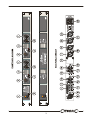
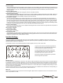
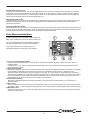
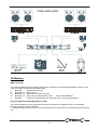
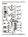
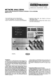
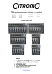
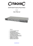
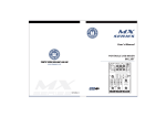
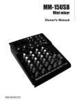
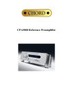
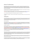
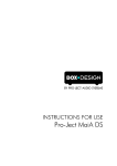
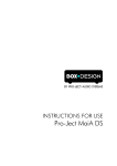
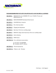
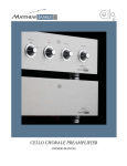
Z-2M & Z-2MR Installation Manual
Includes Zone Remote Installation
Z-2M
Z-2MR
Dual Zone Mixer
Dual Zone Mixer & Remotes
Code 953.003
Code 953.009
™
1
The Z-2M & Z-2MR Dual Zone Mixers
The Z-2M & Z2MR are high quality zone mixers that
are easy to operate while extensive enough in their
installer features. With many years of experience in
the manufacturing of zoning systems for leisure
applications at Citronic we know how important it is
to make our devices operator friendly. The Z-2M &
Z2MR are no exception.
The simple user controls belie the
extensive installer options that are either mounted
on the rear panel or hidden below the top cover,
which cannot be accessed while the mixer is
mounted on in a rack. All the equalisation,
sensitivity and priority controls are installer
accessible only. Full details of which are explained
in the body of this manual.
There are 5 inputs in total; Microphone,
three line and a priority. The priority input can be
used as a fourth line input by engaging it on the
front panel while the other inputs are switched off.
All of these inputs have their own gain control
mounted on the rear panel.
Both of the output zones are balanced
stereo low impedance. There is also a mono
selector switch for each of these outputs.
The rear panel is completed by provision
for the connection of expansion modules to
increase the number of zones (up to six), access
for the remote control option and an IEC AC power
connector.
The user controls for each output zone are
simple. There is a rotary selector switch to select
the input, a microphone level control, a music level
control and a button to activate the priority music
input.
The music channels have an Eq auto
loudness control that maintains the equalisation
settings you set across a wide variation in volume
settings. Normally you would need to increase the
bass in a music signal as you decrease the
volume to maintain the apparent listening balance
between high and low frequencies. In this system
it is not necessary. Simply set up the Eq you wish
at the highest volume setting and the system will
re-balance it for lower volumes.
™
2
™
3
WARNING: In order to obtain the best service from the unit we STRONGLY recommend that you read this
manual before you apply any power.
Front Panel Controls Z-2M
1) AC Power Switch
Switches on or off the AC power to the unit and any expander units that may be plugged into it.
2) Power LED
Indicates green when the power switch is on.
3) Zone 1 (or 2) Input Selector Switch
In position off, (as illustrated) all the music inputs are defeated, the possible exception is the priority input, which is
explained below.
In position Line 1, 2 or 3 the zone output will carry the selected source. The inputs can be labelled to indicate the source.
4) Music Priority Inputs
This switch selects the music source connected to the priority input, and the LED will illuminate to indicate this. The priority
input sensitivity and release times must be set up at the time of installation for this function to operate correctly.
When this function is selected and a signal is present on the input, any music playing on input selected by the selector
switch will be overridden and replaced by the priority input signal. If no other inputs are selected, i.e. the selector switch is
in the “off” position the priority input acts as another ordinary line input. See the section in installer set up on sensitivity
control as this must be set up for the system to work properly.
5) Input Zone Labelling
Spaces are provided to label the zone inputs for the users information.
6) Music Level
This control alters the volume of the music in its associated output zone. It is an overall level control for the zone treating
all inputs the same. To cater for different input levels refer to the rear panel level controls detailed in section (12)
7) Microphone Level
This controls the microphone level in the appropriate zone. This control when set at minimum, will defeat the override
depth to the music signal.
Installation Notes:
The Z-2M & Z-2MR are quick and easy to install using conventional connectors. It’s a good idea to double check all
your interconnections as the Z-2M & Z-2MR will only perform to their optimum if the inputs and outputs are properly made.
Always use good quality connectors such as Neutrik® it’s a small investment that can save your time and money.
Connecting Up
8) Microphone Input
The microphone input is balanced. If you wish to use an unbalanced microphone, short pin 3 to pin 1 (ground) and
connect the signal input pin 2. This microphone has first priority in the system and will override the music signals. Full
details of the override control and EQ settings are detailed in the next section (installer Settings).
9) Microphone Gain
This control alters the input gain of the microphone circuit in order to match the output from the microphone. Adjust this
control so that the microphone level control on the front of the Z-2M provides the required volume range. Reduce this
control if distortion occurs.
10) Alarm Detector
This feature allows you to interface this audio system with the alarm system of the venue. All that is required to detect an
alarm condition is that the two terminals are shorted. The associated push button allows you to choose whether the music
signals are reduced by 25dB or 40dB in the alarm condition.
Note: The microphone input is unaffected by this attenuation so that announcements can still be made.
Note: The terminal you can see unplugs from the unit so that the wiring can be completed remotely as access to the back
of the rack is sometimes awkward. These terminals need to be shorted together by an external relay in the alarm system.
11) Zone Expansion Socket
It is possible to add zones to the system by the addition of Citronic’s Z-2X or Z-4X expanders. This socket makes
interconnection simple and is for the ribbon cable supplied with the expanders.
12) Input Gain Control
Because the inputs of various equipment like CD players and tape decks vary so much the Z-2M & Z-2MR are fitted with
input gain control so that you can match the varying inputs to give the same volume level control range from the music
level control on the front panel or Remote.
13) Input Sockets
Two Phono (RCA Phono jack) connectors for your music input device. This device can be virtually any source, e.g. CD
player, tape deck or satellite feed. If your music source is mono connect to the left and the right input using a proprietary
Phono splitter cable or connector.
™
4
14) Priority Input
This is a special input that will override the music playing in any of the other inputs and automatically route whatever is on
the input to the output. This is especially useful for jukeboxes where the background music from another input is required
when the jukebox is not in use. The sensitivity of the auto signal detect circuit can be altered, see the next section:
Installer Options.
15) Priority Gain Control
This works the same as all the other input gain controls. See feature 5 above.
16) Remote Control Option
This is a blanking plate that needs to be removed if you choose to add the remote control option on the Z-2M. It will need
to be removed for the Z-2MR. Installation of the remote controls will be explained later in the manual. For the Z-2M you
can purchase the remotes as an addition using the part code 953.006
17 & 19) Zone 1 Output
The zone outputs are balanced to minimise noise pickup. A bar environment can be electrically noisy and proximity to
beer coolers and automated pumps may be difficult to avoid. These electronically balanced outputs will reject this kind of
electrical noise and keep the sound system clean of pops and crackles. In the unlikely event you have to use a domestic
HI Fi type amplifier that does not have a professional standard input connect its input to pin 2 (+) and 1 (Ground). In this
mode the output level is lower and better suited to domestic amplifiers, which have a much higher input sensitivity. NB do
not use Pin 3, leave it floating but, also note, you may suffer from electrical noise pickup.
18) Zone 1 Mono Button
If the zone is to be powered using a mono amplifier activating this button will mix the left and right channels and provide a
mono output from both connectors.
20 & 22) Zone 2 Outputs
As per Zone 1 output.
21) Zone 2 Mono Button
As per Zone 1 mono button.
23) AC Power Socket
A standard IEC AC power socket for connecting to the main AC supply. Use only the AC mains power lead supplied with
the unit and check that the supply voltage matches the rating uppermost on the fuse mounted on the socket. This unit is
designed to operate at 220 or 230V (Europe & Asia).
Installer Settings
The Z-2M & Z-2MR have features which are set up by the installer at the time of installation and then secured so that
unskilled operators do not inadvertently re-configure the system and prevent it operating as expected. This sections deals
with these options and how to adjust them.
The illustration shows how the installer adjustment options appear on the top cover of the mixer.
To gain access to these controls the top panel will
need to be removed, use the diagram also printed
on the top panel as a guide to the controls.
Once the settings have been made, replace the
top panel and mount into a rack, this will prevent
any tampering with the system by the user.
We’ll start to explain the settings from top left and
work through them by function.
Microphone Eq
The microphone Eq is separate for each zone. The reason for this is because the nature of the zones can be quite different
in application as well as in acoustic properties. E.g. Zone one could be a restaurant where the ambient noise is low and the
decor is likely to have soft surfaces that will dampen the acoustic reflections while zone two could be a pool hall where the
ambient noise could be high and the acoustics more reflective. To ensure that speech is intelligible the Eq settings in these
two zones need to be quite different.
The first control is the Eq Hi for zone 1 and the second the Eq Hi for zone 2. Below these controls are the corresponding Lo
band Eq controls. Each of these controls provide ± 12dB of lift and cut.
Music Eq
Next there is a similar set of Eq controls for the music signals. Again these are separate for each zone and there is both Hi
and Lo Eq available at ±12dB.
™
5
Override Sensitivity Controls
There are two override sensitivity controls (Top Right labelled Sens), one for the microphone and the other for the priority
music input. These should be adjusted to ensure the override occurs at the time you want it to relative to the input signal
level from the two priority inputs. E.g. If the microphone is left on you can adjust the sensitivity level to ignore background
noises and only respond when someone speaks directly into it.
Microphone Depth Control
This determines by how much the music signals dip in volume when the microphone is used. It can be adjusted to dip very
slightly, more like the use in a DJ environment or disappear almost completely if the system is used for evacuation or
general announcement.
Priority Input Release Control
Allows adjustment of the time taken for the selected input signal to return when the signal on the priority input finishes. It has
a range of 2 to 15 seconds and should be set to avoid premature return during quiet sections on the priority input. Once this
time has elapsed the primary input signal will return gently at a predetermined rate.
Zone Remote Installation
There are two remote control panels supplied with the Z2MR.. They are identical and can be used on either zone.
Once connected these panels can be fitted to standard
UK dual gang light switch or power socket hardware.
If you require remotes for the Z-2M they can be
purchased separately using the part code 953.006
1) Zone 1 (or2) Input Selector Switch
In position Off, (as illustrated) all the music inputs are defeated, the possible exception is the priority input, which is
explained below.
In position Line 1, 2 or 3 the zone output will carry the selected source. The inputs can be labelled using the label set
provided with this manual.
2) Music Priority Inputs
This switch selects the music source connected to the priority input and the LED will illuminate to indicate this. The priority
input sensitivity and release times must be set up at the time of installation for this function to operate correctly.
When this function is selected and a signal is present on the input, any music playing on input selected by the selector
switch will be overridden and replaced by the priority input signal. If no other inputs are selected, i.e. the selector switch is
in the ‘Off’ position the priority input acts as another ordinary line input. See the section on the sensitivity control in your
mixers handbook, as this must be set up for the system to work properly.
3) Input & Zone Labelling
This space is provided to label the input zones available. This can be done by writing directly on to the panel or by
attaching stickers.
4) Music Level
This control alters the volume of the music in its associated output zone. It is an overall level control for the zone treating
all inputs the same. To cater for different input levels refer to the rear panel level controls detailed in the mixers handbook.
5) Microphone level
Controls the microphone level control in the appropriate zone. This control, when set at minimum, will defeat the override
depth to the music signal.
™
6
Installing Remotes
Ensure that the Z-2M or Z-2MR is disconnected from the AC power and place it so you can work on it from the rear panel.
Remove the lid and rear cover panel as shown above. You will need a No.1 (M3) pozi head screwdriver and a 3mm flat
blade screwdriver.
Disconnect the ribbon from the front PCB and feed through the rear of the mixer casing.
The ribbon is plugged directly onto the remote control module- making sure that Pin 1 of the ribbon lines up with Pin 1 on
the PCB.
Ideally the ribbon connection should be undertaken once the remote cable connections have been made, this allows the
maximum working area.
Once the ribbon has been connected the cover of the unit can be replaced.
The recommended cable for remote control is 8 core shielded alarm cable (804.299). The terminals on the module are
colour coded for this cable and there is a P clip for each cable to secure it and the screen to the module. The shield of the
cable should be neatly wound around the cable and make contact with the P clip to make a bond to the metalwork.
™
7
Carefully put the remote control module into the casing and secure it with the two original fixing screws. This end of the
termination is now complete.
Select one of the remote controllers and go to the other end of the control cable wherever it is routed in the installation.
Unplug the terminal strip from its retaining pegs fixed to the circuit board between it and the front panel. Notice, the
terminal connections are colour coded on the back of the PCB to match those at the other end of the cable.
Make the connections to the terminal strip and replace it into the retaining pegs on the PCB. Make sure it is
pushed home firmly. Peal back the braiding on the cable and ensure it is secured by the P clip clamp holding
the cable to the PCB. Notice, the P clip can be rotated through 360º so that cable exit can be in any direction.
This panel can now be fixed to any standard dual UK Lighting or AC power socket hardware.
™
8
CE Marking
EMC Conformity
The Z-2M & Z-2MR have been tested to demonstrate compliance with the EMC 89/336/EEC directive, under
which the following harmonised standards apply:
i)
EN55020
Radiated RF Immunity
ii)
EN61000-4-2 ESD Immunity
iii)
EN61000-4-4 Mains Burst Transient Immunity
iv)
EN61000-3-2 Mains Harmonic Disturbance Limits
Generic Std EN50081-1
v)
EN55022
(Class B) Conducted Mains RF Emission Limits Generic Std EN50081-1
Electrical Equipment Safety Regulations (1994)
The Z-2M & Z-2MR have been designed and tested to demonstrate compliance to the LVD 73/23/EEC
directive, using the following standard.
i) EN60065 Safety requirements for mains operated electronic equipment for household and similar general
use
™
9
Block Diagram
™
10
Technical Specification
Parameter
Sensitivity
Input Impedance
Source Impedance
Gain
S/N Ratio*
Frequency Response**
THD + Noise***
Microphone
-53dBu
2K Ohms
150 Ohms
20-53dB
>73dB
15Hz to 22KHz
<0.04%
Line/Priority
0dBu
50Kohms
2K Ohms
-10dBto +10dB
>75dB
10Hz to 30KHz
<0.04%
Zone Outputs
Left & Right
0dBu (775mV RMS) Bal XLR
Microphone EQ
Lo
Hi
Lo
Hi
Sensitivity
Depth
Sensitivity
Release
Connector
Music Attenuation
Voltage
AC Fuse
±12dB @ 80Hz
±12dB @ 10KHz
±12dB @ 80HZ
±12dB @ 10KHZ
-1dBu to -20dBu
-2dB to -24dB
-2dBu to -28dBu
2 to 15 Seconds
2 Way Terminal Block
25dB or 40dB
230VAC 50Hz (200 to 254V)
230V T200mA
Music EQ
Microphone Override
Priority Override
Alarm Interface****
Power Requirements
*
**
***
****
Measured at Zone Output 22Hz to 22KHz Filtered
Measured at -1dB w.r.t 0dB referenced at the zone output
Measured at zone output 30KHz Lo Pass filtered
Active when contacts shorted by external isolated relay contacts from the alarm system.
Other products in the System Install Range
Z-2X - Zone Expansion Module 953.012
The Z-2X is a quick and easy to install expansion unit for the Z-2M and Z-2MR. The mic & music input, alarm,
override signals and power supply rails are liked from the zone mixer (Z-2M or Z-2MR) via a 2-way IDC ribbon
socket. Giving you an extra two zones.
Z-4X – Zone Expansion Module 953.015
The Z-4X is a quick and est to install expansion unit for the Z-2M and Z-2MR. The mic & music input, alarm,
override signals and power supply rails are liked from the zone mixer (Z-2M or Z-2MR) via a 2-way IDC ribbon
socket. Giving you an extra four zones.
Z-5DM Five Zone Mixer 953.018
The Z-5DM is a high quality distribution mixer housed in a 1U 19" rack mounting package, which provides the
means to expand 2 stereo line inputs into 5 stereo zone outputs. Each zone has an individual mono switch and
separate level controls for both stereo inputs. Professional XLRs on all input and outputs, cater for both
balanced and unbalanced connection.
Zone Remote Control 953.006
The remote control can be fitted in any location you prefer allowing you to control a specific zones music output,
and volume levels. There are two remote control panel supplied with the Z-2MR & z-2X and four with the Z-4X.
Once connected these panels can be fitted to a standard UK dual gang light switch or power socket hardware.
™
11
For other Citronic products in the range, visit…..
www.citronic.com
™
12