1
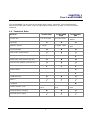
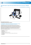
LanXPLORER Manual 1 These operating instructions contain confidential information from IDEAL INDUSTRIES Ltd. The information contained in this document may be reproduced or otherwise used only with prior written approval by IDEAL INDUSTRIES Ltd. IDEAL INDUSTRIES Ltd and the Logo of IDEAL INDUSTRIES Ltd are registered trademarks of IDEAL INDUSTRIES Ltd. All other product names mentioned in these operating instructions are products of the associated manufacturers or protected by their copyrights. Manual Article Number: P-150801_V1.0 © 2010 IDEAL INDUSTRIES Ltd 2010-12 2 IDEAL INDUSTRIES Ltd standard terms of guarantee The General Terms of Business of the local affiliate of IDEAL INDUSTRIES Ltd. apply. Safety precautions Caution on handling rechargeable batteries (accumulator batteries) All nickel/metal hydride (Ni-MH) rechargeable batteries generate sufficient electrical current to cause injury and/or damage regardless of the charge state indicated. Nickel/metal hydride (Ni-MH) rechargeable batteries should never be exposed to fire or disposed of with normal domestic waste. Nickel/metal hydride (Ni-MH) rechargeable batteries can explode when exposed to open flames. These batteries constitute special hazardous waste and can contaminate the ground water when disposed of at a waste dump. Observe the following instructions precisely when handling rechargeable batteries to avoid injury. When a rechargeable battery is not installed in the hand-held instrument, it should be stored in a clean, dry and non-conductive package. Ensure that the contracts on the rechargeable battery do not come into contact with conductive materials. Avoid touching the contact surfaces on the rechargeable battery. The rechargeable batteries can be charged while installed in the hand-held instrument. Charging in any other manner can result in the rechargeable battery exploding. Install, remove, store and charge the rechargeable batteries only in non-explosive atmospheres. Observe the operating and storage temperatures (see Chapter 1.2. Dimensions, Weights, Operating Conditions). Do not allow children or persons not familiar with the safety precautions in these operating instructions to handle or charge rechargeable batteries. Never open the rechargeable battery case. There are no user-serviceable parts in the case and the rechargeable batteries contained in the case are not replaceable. 3 Disclaimer IDEAL INDUSTRIES Ltd assumes no liability for death, injury, or damage to equipment or property resulting from improper use of the rechargeable batteries. IDEAL INDUSTRIES Ltd assumes no liability for subsequent damage resulting from modifications to the rechargeable batteries or the charger or use of the same. All rights to technical modification reserved. Environmental Protection Please contact a representative of IDEAL INDUSTRIES Ltd. if you have any questions regarding safe handling and disposal of the rechargeable batteries used in the LanXPLORER. Contact information is given in the Chapter Customer Service. Working with the LanXPLORER The factory settings on the LanXPLORER are based on general standards, recommended industrial standards for cable and network links, state-of-the-art technical information from the international committees for LAN cable standards, the LAN industry as well as values gained from tests and experience of IDEAL INDUSTRIES Ltd. Before performing any measurements IDEAL INDUSTRIES Ltd recommends clarifying with the principal or project manager, precisely which measurements are to be performed to ensure that all relevant parameters are maintained. Notes on use of these operating instructions The following symbols used in these operating instructions indicate that the user should proceed with particular care to prevent injuries to humans, damage to the LanXPLORER or to the system to be tested. ATTENTION! CAUTION! NOTE: This symbol indicates potential lethal voltages. This poses a hazard for the life and/or health of the person performing the action or any other humans in the vicinity. This symbol indicates that the action in question may pose a hazard for the environment or damage technical equipment. General notes, additional information or assistance are given here. Typographic conventions Bold face Indicates a key on the LanXPLORER. Italics Indicates a menu option in these operating instructions. Quotation marks " " Indicate a "Screen message" Asterix * Indicates a module-related option xxx Indicates a softkey 4 Table of Contents CHAPTER 1 Your LanXPLORER..................................................................7 1.1. Technical Data ............................................................................................. 7 1.2. Dimensions, Weights, Operating Conditions ..................................................... 8 1.3. Equipment included Basis version ................................................................... 9 CHAPTER 2 Instrument description ........................................................ 10 2.1. LanXPLORER .............................................................................................. 10 2.2. Power options ............................................................................................ 13 CHAPTER 3 Settings...............................................................................15 3.1. Principles................................................................................................... 15 3.2. System ..................................................................................................... 15 3.3. RJ45 ......................................................................................................... 21 3.4. Fibre-optic cable......................................................................................... 21 3.5. Tests ........................................................................................................ 21 3.6. IP ............................................................................................................. 27 3.7. VLan ......................................................................................................... 28 CHAPTER 4 Test summary......................................................................29 CHAPTER 5 Test setup ...........................................................................30 5.1. Ports......................................................................................................... 30 5.2. Passive wiring ............................................................................................ 30 5.3. Active wiring .............................................................................................. 32 5.4. Inline Test ................................................................................................. 32 5.5. Fibre-optic cable......................................................................................... 33 5.6. WiFi .......................................................................................................... 34 CHAPTER 6 Test description and procedure ............................................35 6.1. Test summary ............................................................................................ 35 6.3. Wiremap test ............................................................................................. 36 6.4. Testing a passive route without remote / smart remote ................................... 38 6.5. Netmap ..................................................................................................... 39 6.6. Verify........................................................................................................ 40 6.7. Ping .......................................................................................................... 41 6.8. Voice over IP (VoIP).................................................................................... 41 6.9. Trace Route ............................................................................................... 42 6.10. Blink ......................................................................................................... 43 6.11. Power over Ethernet (PoE)........................................................................... 43 6.12. Loop ......................................................................................................... 44 6.13. PC Diagnosis .............................................................................................. 44 6.14. Statistics ................................................................................................... 45 6.15. WiFi .......................................................................................................... 46 CHAPTER 7 7.1. Wiring test on fibre-optic conductors and SFP modules ........48 Safety precautions ...................................................................................... 48 5 Table of Contents 7.2. Instructions for cleaning SFP modules and patch cables................................... 48 CHAPTER 8 LanXPLORER Firmware Update.............................................49 CHAPTER 9 Spare parts - Socket inserts .................................................50 CHAPTER 10 Customer service .............................................................. 51 10.1. Technical Support and Service ..................................................................... 51 10.2. Internet .................................................................................................... 52 6 CHAPTER 1 Your LanXPLORER The LanXPLORER can be used to test RJ45 cable routes, networks, connected Ethernet devices and fibre-optic cable used for high speed transmission of data in communications networks. 1.1. Technical Data Function Screen size LanXPLORER LanXPLORER PLUS LanXPLORER PRO 3.5” TFT colour 3.5” TFT colour 3.5” TFT colour, TOUCH Wiremap Number of ports 1 copper 1 copper 1 WiFi 2 copper 1 fibre, WiFI Tone Generator PoE / PoE+ measurement PoE / PoE+ device load measurement Basic active tests (DHCP, Ping etc.) Top Ten test (Talkers, protocols etc.) Device map / Netverify Inline testing VoIP measurement VLAN Discovery 802.1x Loopback Via USB memory stick Via USB memory stick Via USB memory stick Internal battery charging External power supply Results transfer to PC 7 Chapter 1 Your LanXPLORER Maintenance of test standards: ANSI/TIA/EIA 568A, 568B Types of cable Wiring in compliance with UTP/SCTP/FTP CAT 3/5e/6A/7 (100 Ω) 1.2. Dimensions, Weights, Operating Conditions Dimensions: (L) 205 mm x (W) 98 mm x (D) 45 mm Weights: Handheld display 650 g (incl. Batteries) Batteries 180 g Batteries: AA Alkaline NiMH1* (battery pack) Operating time with rechargeable batteries: 4 hours under normal operating conditions Charging time: In instrument 8 hours Operating temperature (min./max.): 0o C to +40o C (use only when instrument temperature is close to ambient temperature!) Storage temperature (min./max.): -20o C to +70o C Relative humidity: 5% to 90%, non-condensing 1 May not be included in scope of delivery 8 Chapter 1 Your LanXPLORER 1.3. Equipment included Basis version Quantity Description 1 Measuring instrument 1 Smart remote 1 Carrying case 2 STP Patch cables, 30 cm 1 CD with operating instructions 1 Brief instructions 6 AA Alkaline batteries 9 CHAPTER 2 Instrument description 2.1. LanXPLORER The LanXPLORER guarantees control of the settings and test functions while performing individual tests. 2.1.1. Controls and Interfaces/Connections Figure 1: LanXPLORER - Front view Item Controls Description 1 ON/OFF For switching the LanXPLORER on and off. Hold key down: To restart. 2 Arrow keys / Enter For navigation in menus on TFT display / Entry key for activation and editing in selected menu. 3 Autotest Immediate execution of pre-programmed test procedure. 4 Function keys F1 to F4 For selection of softkeys displayed on screen. 5 TFT display Display of menus, test results, graphs, actions selected and function keys. Touchscreen* for display and selection of of menus, test results, graphs, action selection and function keys. 6 Escape Return to previous menu or discontinue and exit current menu without saving changes. LEDs Display of charging status Illuminated green: Batteries are being charged. Off (with charger connected): Batteries are charged. Flashing green: Batteries cannot be charged – AA cells are fitted, battery is too hot or too cold. Flashing red: Batteries cannot be charged – temperature is too high. 7 10 Chapter 2 Instrument description Figure 2: LanXPLORER – Top and side views Item Interfaces / Connections Description 8 RJ45 1 network interface Terminal for copper cables. 9 Fibre-optic network port Terminal for fibre-optic cables. 10 RJ45 2 diagnostic port Inline interface for copper cables (active devices) 11 USB external memory port Port for connecting USB storage device. 12 Power socket Socket for power pack 11 Chapter 2 Instrument description 2.1.2. Image on TFT display The standby screen appears when the LanXPLORER is ready for operation. Item Image Description 1 Instrument mode Indicates mode to which instrument is set. 2 Jobname Indicates job in which project is being processed. 3 Physical test medium Indicates test medium connected to LanXPLORER 4 Battery charge Indicates battery operation or external power supply and charge state of rechargeable battery. 5 Time 6 LanXPLORER 7 Menu points 8 Softkeys Figure 3: Image on TFT display 2.1.3. Touchscreen* Possible options in menus are indicated by symbols on the display. Simply touch the symbol to select the option indicated. 2.1.4. Arrow keys / Enter Possible options in menus are indicated by symbols on the display. The options can be selected by moving to the corresponding symbols with the arrow keys. Confirm the selection by pressing the Enter key 2.1.5. Softkey Possible options in menus are indicated by softkeys at the bottom of the screen. The Function keys (F1 – F4) below the softkeys can be used to select options. The example shows optional selection of the Setup softkey with the softkeys at the bottom of the screen. Selection can be accomplished with Function key F4. Figure 4: Softkeys and function keys 12 Chapter 2 Instrument description 2.2. Power options The LanXPLORER can be operated with replaceable AA alkaline batteries as well as rechargeable AA batteries or with an NiMH rechargeable battery pack. The LanXPLORER can operate for approx. 4 hours with the rechargeable batteries. The actual operating time in battery mode depends on various factors such as use of the background lighting and ambient temperature. If the rechargeable battery charge level drops to below the required voltage, a warning message appears. The instrument switches off automatically before any negative effects occur for the test results. To preserve your rechargeable batteries, it is possible to set the LanXPLORER to switch off automatically after a certain time with no activity (see settings Fehler! Verweisquelle konnte nicht gefunden werden.). To increase the service life of your rechargeable batteries we recommend removing the batteries when the instrument is not used for longer periods of time. 2.2.1. Mains Operation The LanXPLORER can be operated using an external DC power source (AC/DC power pack). During operation of the instrument with the AC/DC charger/power pack, note that: The battery pack in the instrument is trickle charged; A mains plug is shown in the upper right-hand area on the LanXPLORER; Rechargeable AA batteries are not charged in the instrument. CAUTION! Use only the power pack supplied with the instrument. Other power packs can damage the tester. NOTE: When testing shielded cables do not connect mains power, because otherwise a shortcircuit to earth could occur leading to output of warnings for protection of the tester input. 2.2.2. Charging rechargeable batteries NOTE: The charging time depends on the charge level of the batteries. Battery pack The battery pack for the LanXPLORER can be charged in the LanXPLORER using the charger/power pack. A time of approximately 8 hours is required to completely charge the battery pack in the instrument. Rechargeable AA batteries It is necessary to charge rechargeable AA batteries externally with a charger. They cannot be charged in the LanXPLORER. 13 Chapter 2 Instrument description 2.2.3. Removing / installing rechargeable batteries When the batteries are removed the LanXPLORER saves the data and settings in the batterybuffered flash ROM. 1. Open the kick stand. 2. Remove the battery cover. CAUTION! The battery pack or battery holder is connected to the LanXPLORER with a cable. When removing the batteries, do not pull on the cable - damage to instrument and connector could occur. Figure 5: Changing batteries 3. Remove the battery pack or battery holder. 4. Detach the connector for the battery pack or battery holder from the instrument. 5. If applicable, remove the batteries from the battery holder. Install batteries in opposite order. Figure 6: Removing batteries 14 CHAPTER 3 Settings 3.1. Principles All instrument settings can be made with the Setup menu on the standby screen. Over the Setup menu it is possible to navigate to any of the submenus to make settings there. 1. Select the menu point Setup. Figure 7: Standby screen 2. Make the settings by selecting the applicable menu point. Figure 8: Settings 3.2. System Instrument management is possible in the "System" menu. 1. Select the menu point "System". 2. Make the settings by selecting the applicable menu point. Figure 9: System 15 Chapter 3 Settings 3.2.1. Owner This menu allows information to be saved on the technician performing the work, the company and the client. 1. Select the menu point "Owner". 2. Select the desired option. 3. Enter the desired information with the alphanumeric keys. 4. Save the entry made with OK. You can exit the menu without saving the changes with Cancel or Escape. 5. Save the entry made with Apply. You can exit the menu without saving the changes with Escape. Figure 10: User Information 3.2.2. Preferences This menu allows settings to be made for the display and display format. Display settings 1. Select the menu point "Pref". 2. Select the desired option. 3. Set the desired option. 4. Save the entry made with Apply. You can exit the menu without saving the changes with Escape. Figure 11: Display Image Description Auto Off Defines the time after which the LanXPLORER will shut off automatically, if not in use. Backlight Defines the time after which the back light dims automatically. Keyclick Activates/deactivates an acoustic signal when selecting menus and options. Screen Calibration* Calibration of touchscreen. Screen calibration* 1. Select the menu point "Screen calibration". 2. After the LanXPLORER has automatically restarted touch the cross-hairs, which appear one after another in each corner and in the middle of the screen, as precisely as possible with the pointer or a thin pin. Successful calibration of the screen is confirmed by a check mark. The LanXPLORER restarts automatically after screen calibration. 16 Chapter 3 Settings Display settings 1. Select the menu point "Pref". 2. Select More. 3. Select the desired option. 4. Set the desired option. 5. Save the entry made with Apply. You can exit the menu without saving the changes with Escape. Figure 12: Display Image Description Number Format Definition of format for display of numbers. Date Format Definition of format for display of the date. Length Units Definition of units of measure for length measurement in ft or m (feet or meters). The default setting depends on the language set. 3.2.3. Update The LanXPLORER software can be updated with this menu (see CHAPTER 8). 3.2.4. Jobs Projects can be created and managed with this menu. NOTE: Job management can also be selected directly with the menu point "Jobs" on the standby screen. The name of the current job directory is shown on the standby screen on the TFT display. When storing the Autotest it is possible to keep this job directory, activate a job directory already present or to create a new job directory. 1. Select the menu point "Jobs" to obtain a list of all jobs created on your LanXPLORER. Viewing a present job and test details 1. Select a job from the list, to view the test results and their status. 2. Select a test to obtain further details on the test. 3. Select a single test to obtain further details on the test. Creating a new job 1. Select Options. 2. Select the menu point "New". 3. Select the individual fields and enter the desired information with the alphanumeric keys. 17 Chapter 3 Settings 4. Save the entry made with OK. You can exit the menu without saving the changes with Cancel or Escape. 5. Save the entry made with Apply. You can exit the menu without saving the changes with Cancel. Changing a job already present 1. Select the job you want to change. 2. Select Options. Menu point Description Current Activate a current job for editing. Edit Change job information. Delete Delete a job. To USB Save job on a USB storage device. View View jobs New Create new job. Figure 13: Job management 3.2.5. Save This menu allows you to export the current LanXPLORER configuration to a USB storage device; load a configuration stored on a USM storage device on the LanXPLORER. NOTE: Data export and data import is accomplished exclusively to/from a USB storage device connected to the LanXPLORER. 1. Select the menu point "Save". 2. Select Save to store the LanXPLORER configuration on a USB storage device. 3. Select Load to load a configuration from a USB storage device on the LanXPLORER. The exported file is saved on the USB storage device under the Name nmmcfg.xml. to load a configuration on the LanXPLORER, it is necessary for the file with the same name to be present on the USB storage device. 18 Figure 14: Exporting and importing jobs Chapter 3 Settings 3.2.6. About This menu contains information on your LanXPLORER. 1. Select the menu point "About". Figure 15: Instrument information 3.2.7. Language The language can be set with this menu. The following languages can be selected for menu guidance on the LanXPLORER: English German French Spanish 1. Select the menu point "Lang". 2. Select the desired language in the Option menu. 3. Save the entry made with Apply. You can exit the menu without saving the changes with Escape. 3.2.8. Date and Time Correct setting of the date and time is important for reliable identification of the data records and test logs. 1. Select the menu point "Time". 19 Chapter 3 Settings Setting the date 2. Select the menu point "Date". 3. Set the current date by selecting the month, year and day. 4. Save the entry made with Apply. You can exit the menu without saving the changes with Escape. NOTE: You can select the previous month or next month with the right and left arrow keys on the edge of the display. Figure 16: Date Setting the time 1. Select the menu point "Time". 2. Set the current time by selecting the hour, minute and seconds. 3. Save the entry made with Apply. You can exit the menu without saving the changes with Escape. Figure 17: Time 3.2.9. Factory You can set the LanXPLORER back to the factory settings with this menu. All settings are set back to the factory settings. All data is deleted from the memory. CAUTION! The data cannot be restored after deleting with the "Reset" menu. All tests stored previously are deleted irrevocably. 1. Select the menu point "Factory". 2. With Reset returns the instrument to the factory settings and any settings you have made are deleted. 3. You can exit the menu without saving the changes with Cancel or Escape. Figure 18: Resetting instrument to factory settings 20 Chapter 3 Settings 3.3. RJ45 This menu allows configuration of how the RJ45 interface connects to the network. 1. Select Setup. 2. Select the menu point "RJ45". Option Description Auto Negotiation Enable: Automatic recognition of the network speed. Disable: It is necessary to set the communication rate and mode manually. Speed2 Setting the network speed. Mode Full Duplex (all pairs are used for transmitting and receiving). Half Duplex (pairs are used for transmitting or receiving). MAC2 Display of MAC address. 2 Figure 19: RJ45 Settings 3. Save the entry made with Apply. You can exit the menu without saving the changes with Escape. 3.4. Fibre-optic cable The SFP version is indicated in this menu. 1. Select Setup. 2. Select the menu point "Optical". 3.5. Tests This menu allows settings to be made for the tests. 1. Select Setup. 2. Select the menu point "Tests". Figure 20: Test settings 2 This setting is possible only when Auto Negotiation is disabled. 21 Chapter 3 Settings 3.5.1. Cable tests This menu allows settings to be made for "wiremap" and "tone generator". 1. Select the menu point "Wiremap". Figure 21: Cable tests - overview Setting the wiremap This menu allows you to set the type of wiring. 1. Select the menu point "Wiremap". Option Description Cable Type Selection of type of cable. Display Pref Selection of wiring schematic. Xover Allowed Permit cross-over cables. Use Custom NVP Use own NVP value. Custom NVP 3 Entry of cable-specific NVP value (Nominal Velocity of Propagation) in percent, e.g. 79 for 79%. Figure 22: Wiremap 2. Select the desired option. 3. Select the desired test parameters or enter the desired information with the alphanumeric keys. 4. Save the entry made with Apply. You can exit the menu without saving the changes with Escape. 3 Allows precise length measurement of the pair. 22 Chapter 3 Settings Setting the tone generator This menu allows you to set the melody on the tone generator and the pin or pair to be found. 1. Select the menu point "ToneGen". 2. Select the option Song Id to set the melody. 3. Set the desired option. 4. Select the option Wire Id to set the pin or pair to be found. 5. Set the desired option. 6. Save the entry made with Apply. You can exit the menu without saving the changes with Escape. Figure 23: Tone generator 3.5.2. Autotest The Autotest options can be set in this menu. You can set the tests to be performed by actuating the Autotest button or selecting the "Autotest" menu. 1. Select the menu point "Autotest". 2. Activate or deactivate the option by selecting. An activated option is indicated by a check mark in the box. 3. Save the entry made with Apply. You can exit the menu without saving the changes with Escape. Figure 24: Autotest settings 3.5.3. IP Tests This menu allows settings to be made for the IP test. 1. Select the menu point "IP Tests". Figure 25: IP Tests 23 Chapter 3 Settings Ping This menu allows settings to be made for the ping test. 1. Select the menu point "Ping". Option Description Target Select the target address to which the ping is to be sent. Use the option … to select the list with the target addresses you have saved. Count Number of pings sent. Pause Period of time between sending pings in milliseconds. Length Size of ping package sent. Figure 26: Ping 2. Select the desired option. 3. Enter the desired information with the alphanumeric keys. 4. Save the entry made with Apply. You can exit the menu without saving the changes with Escape. Netmap This menu allows settings to be made for the netmap test. Option Description Local Network Scan local network - automatic setting is used. Custom Network Scan specific network area. 1. Select the menu point "Netmap". 2. Select the area to be scanned by activating or deactivating the option Local Network or Custom Network. The option activated is indicated by a check mark in the box. 3. Select the desired option. 4. Select the desired test parameters or enter the desired information with the alphanumeric keys. 5. Save the entry made with Apply. You can exit the menu without saving the changes with Escape. 24 Figure 27: Netmap Chapter 3 Settings VoIP (Voice over IP)4 This menu allows settings to be made for the quality parameter of the VoIP test. The LanXPLORER compares each call with the set quality parameters and evaluates the call. 1. Select the menu point "VoIP". Option Description Figure 28: VoIP VOIP Port 1 Setting the communication port 1 VOIP Port 2 Setting the communication port 2 Jitter (ms) Limit value for the measuring parameter Jitter Delay (ms) Limit value for the measuring parameter Delay Lost Pkts (%) Limit value for the measuring parameter of lost packages 2. Select the desired option. 3. Enter the desired information with the alphanumeric keys. 4. Save the entry made with Apply. You can exit the menu without saving the changes with Escape. T-Route (Trace Route) This menu allows settings to be made for the trace route test. 1. Select the menu point "T-Route". Option Description Target Select the target address to which the ping is to be sent. Use the option … to select the list with the target addresses you have saved. Max Hops Set the maximum number of hops to the target address. Timeout Maximum waiting time in seconds. Type Set ICMP or UDP. Figure 29: Trace Route 2. Select the desired option. 3. Select the desired test parameters or enter the desired information with the alphanumeric keys. 4. Save the entry made with Apply. You can exit the menu without saving the changes with Escape. 4 The version of going to press can only be detected by calling up using SIP standard using the LanXPLORER. 25 Chapter 3 Settings Verify This menu allows settings to be made for comparing netmaps. 1. Select the menu point "Verify". 2. Set the desired option. 3. Save the entry made with Apply. You can exit the menu without saving the changes with Escape. Blink This menu allows settings to be made for the tone generator blink rate. 4. Select the menu point "Blink". 5. Set the desired option. 6. Save the entry made with Apply. You can exit the menu without saving the changes with Escape. Loop This menu allows settings to be made for the loop test. 1. Select the menu point "Loop". 2. Set the desired option. 3. Save the entry made with Apply. You can exit the menu without saving the changes with Escape. 3.5.4. Targets This menu point allows target addresses to be entered and managed for use in the individual tests. 1. Select the menu point "Targets". Softkey Description Add Enter a new target address. Delete Delete a target address. Edit Change a target address. Figure 30: Targets Adding a target address 2. Select Add. 3. Enter the target address with the alphanumeric keys. 4. Save the entry made with OK. You can exit the menu without saving the changes with Cancel or Escape. 5. Save the entry made with Apply. You can exit the menu without saving the changes with Escape. 26 Chapter 3 Settings Deleting a target address 1. Mark the target address to be deleted. 2. Select Delete. Changing a target address 3. Mark the target address to be changed. 4. Select edit. 5. Enter the new parameter with the alphanumeric keys. 6. Save the entry made with Apply. You can exit the menu without saving the changes with Escape. Selecting a target address 1. Mark the target address for the test. 2. Select Select. 3. Save the entry made with Apply. You can exit the menu without saving the changes with Escape. 3.6. IP This menu allows settings to be made for logging onto a network. 1. Select Setup. 2. Select the menu point "IP". Option Description IP Address Dynamic: Automatic recognition of the network properties. Static: With this option it is necessary to set the network properties manually. IP Address5 Display of IP address. NetMask5 Display of network mask. Gateway5 Gateway setting. DNS15 DNS1 setting. DNS25 DNS2 setting. Figure 31: IP NOTE: When working with the Static option, request the required information on the IP address, NetMask Gateway and DNS server from your system administrator. 3. Select the option IP Address to set Dynamic or Static. 5 This setting is possible only when IP Address is set to Static. 27 Chapter 3 Settings 4. Select the desired option5. 5. Enter the desired information with the alphanumeric keys5. 6. Save the entry made with Apply. You can exit the menu without saving the changes with Escape. 3.7. VLan This menu allows settings to be made for testing in virtual LANs. 1. Select Setup. 2. Select the menu point "VLan". Image Description VLAN Disabled: Deactivate virtual network recognition. Enabled: Activate virtual network recognition. VLAN ID Manual entry of virtual LAN ID 3. Select the option VLAN to set virtual LAN recognition. Figure 32: VLan 4. Select the option VLAN ID and enter the desired information with the alphanumeric keys. 5. Save the entry made with Apply. You can exit the menu without saving the changes with Escape. 28 CHAPTER 4 Test summary This short chapter gives an overview of the tests which can be run with with your LanXPLORER model in the different connection versions. Active wiring Inline (only LanXPLORERPro) Fibre-optic cable WiFi IP Mac Link Ping Netmap Test setup Test Passive wiring Autotest Wiremap ToneGen VoIP Trace Route Network Verify Loop PC Diagnosis PoE Load Top Ten Blink Virtual Lan Scan 29 CHAPTER 5 Test setup The following sections explain the typical test setup for the individual tests with the LanXPLORER. 1. Confirm with the ON button to start the LanXPLORER. 2. Connect the LanXPLORER, if necessary. 3. Select the port to be tested. 4. Select Detect or Scan to start recognition. NOTE: The LanXPLORER automatically checks whether power is present on connected cables. If power is recognized, it is indicated by the LanXPLORER. This automatically prevents damage to the tester. In this case it is not possible to run a test. Disconnect the power source from the tester immediately. 5.1. Ports This menu allows you to determine whether a fibre-optic cable, a copper line or a wireless network is to be tested. 1. Select the menu "Ports". 2. Select the desired option. Option Description Optical Fibre-optic cable RJ45 Copper cable WiFi Wireless network (WLAN) Figure 33: Ports 5.2. Passive wiring This function allows all cables not under power to be tested. If it is not possible to connect cables directly to the interfaces present on the LanXPLORER, the cable can be connected to the LanXPLORER using an adapter. 5.2.1. Testing a passive link without remote / smart remote When testing a passive link, the instrument tests the connected cable for: Length; Short-circuit. 1. Select the menu "Ports" "RJ45". 2. Disconnect the cable link to be tested from all network components. 30 Chapter 5 Test setup 3. Connect cable path earth to the RJ45 network port on the LanXPLORER. 4. Select Run to start recognition of the cable path. 5.2.2. Testing a passive link with remote6 / smart remote7 When testing a passive link with remote, the instrument tests the connected cable for: Length; Short-circuit; Pin mixup, split pair; Open / broken conductors; Error location. Item Description 1 Remote / smart remote 2 Wall Outlet 3 Patch Panel 4 LanXPLORER Figure 34: Typical test setup for passive cable path with smart remote. 1. Select the menu "Ports" "RJ45". 2. Disconnect the cable link to be tested from all network components. 3. Connect cable path earth to the RJ45 network port on the LanXPLORER. 4. Connect a remote / smart remote to the other end of the cable path. 5. Select Run to start recognition of the cable path. 6 7 When testing a passive link with remote, the LanXPLORER can recognise pair errors. When testing a passive link with smart remote, the LanXPLORER can recognise pin errors. 31 Chapter 5 Test setup 5.3. Active wiring This function allows all Ethernet-compatible devices to be tested. 1. Select the menu "Ports" "RJ45". 2. Connect a network cable to the Ethernetcompatible device to be tested. 3. Connect the free end of the cable path to the RJ45 network port on the LanXPLORER. Figure 35: Typical test setup for an active cable path. 4. Select Detect to start recognition of the Ethernet-compatible device. Item Description 1 IP address of connected device. 2 Transfer rate of connected device. FD – Full Duplex: Pairs are used for transmitting or receiving. HD – Half Duplex: Pairs are used for transmitting or receiving. 3 Type of connection Crossover - Reversed connection. Straight Straight connection. 4 Recognition of power over Ethernet. PoE PoE present. No-PoE PoE not present. Figure 36: Active wiring test 5.4. Inline Test Connect the LanXPLORER between an Ethernetcompatible device and the network for the inline test. During this test the LanXPLORER measures the traffic between the connected device and the network. If PoE is present, PoE-specific parameters can also be measured. 1. Select the menu "Ports" "RJ45". 2. Connect a network cable to the Ethernetcompatible device to be tested. 3. Connect the free end of the cable path to the RJ45 network port on the LanXPLORER. 4. Connect a network cable to the network. 32 Figure 37: Typical test setup for inline test Chapter 5 Test setup 5. Connect the free end of the cable path to the RJ45 diagnostic port on the LanXPLORER. 6. Select Detect to start recognition of the Ethernet-compatible device. Item Description 1 Network connection status 2 Connection status of connected Ethernet device. 3 IP address Figure 38: In Line Test 5.5. Fibre-optic cable This function allows all Ethernet-compatible devices to be tested in the end point mode. NOTE: This test function can be used only at an Ethernet transfer rate of 1000 Mbit/s. 1. Select the menu "Ports" "Optical". 2. Connect a fibre-optic cable to the Ethernetcompatible device to be tested. Figure 39: Typical test setup for testing with fibre-optic cable 3. Connect the free end of the cable path to the network port for fibre-optic conductors on the LanXPLORER. 4. Select Detect to start recognition of the Ethernet-compatible device. Item Description 1 Transfer rate of connected device. 2 IP address of connected device. Figure 40: Fibre-optic cable 33 Chapter 5 Test setup 5.6. WiFi With this test the LanXPLORER can be connected with all access points and test wireless networks within reception range. An overview the tests available is given in Table CHAPTER 4. 1. Select the menu "Ports" "WiFi". 2. Select Scan to start recognition of the network. Image Description SSID SSID of access point. CH Channel Security protocol 3. Select Run to start recognition of the network again. SEQ Abbildung \* ARABIC 41 4. Select Details to view further information on individual networks. 34 CHAPTER 6 Test description and procedure The availability of individual tests depends on the model version and test setup of the LanXPLORER. An overview the the tests available is given in Table CHAPTER 4. 6.1. Test summary This menu shows all tests possible with the current wiring. In addition it shows which tests have already been performed and the associated pass/fail results. 1. Connect the LanXPLORER in the desired manner. 2. Select the menu point "Tests" on the standby screen. Symbol Overall test results Test not performed. Test performed and evaluated as passed. Test performed and evaluated as failed. Figure 42: Test summary 6.1.1. Performing individual tests 1. Select the desired individual test. 2. Perform the test. The result is stored in the short-term memory and displayed in the test summary. 6.1.2. Resetting test results 1. Select reset in order to delete all individual tests shown in the test summary. All test results are deleted from the short-term memory. 1. Select reset in order to reset all marked individual tests that are shown in the test summary. All test results of the marked individual tests are deleted from the short-term memory. 6.1.3. Saving test results 1. Select Save to store all test results in the current job. All test results are stored in the current job and can be managed there. 35 Chapter 6 Test description and procedure 6.2. Autotest The autotest feature allows the installation to be checked quickly and easily. After pressing the AUTOTEST button, the LanXPLORER automatically runs the individual tests set. Selection of the individual tests in the test series depends on the instrument settings and the type of wiring to be tested. 6.2.1. Run Autotest 1. Connect the LanXPLORER in the desired manner. 2. Set the Autotest options (the Autotest option settings are described in Chapter 3.5.2). 3. Select Run to start the Autotest. 6.2.2. Overall pass/fail result After conclusion of the test series, the LanXPLORER displays an overall pass/fail result as well as the individual pass/fail results. Symbol Overall Autotest results The Autotest is evaluated as passed all total, when all individual tests are passed. The Autotest is evaluated as failed all total, when at least one individual test was failed. You can view the results of the individual tests, save the results or make Autotest settings. Figure 43: Autotest - Complete overview Display of individual test results 4. Select the desired individual test. 5. Select More to view additional details on the specific test results. 6. Press Escape to return to the previous screen. 6.3. Wiremap test Short circuits, discontinuities and erroneous circuits can be localised with the aid of the wiremap test. The test results are displayed in the form of a graph to facilitate evaluation. Any faults indicated in the wiremap test should be remedied before performing further tests, because this would result in errors in the other tests. The wiremap test guarantees the following minimum thresholds for error recognition (based on four conductor pairs, optional shielding): All wiring errors or combined wiring errors are indicated in the wiremap as faults. Combinations of up to three interruptions, short-circuits or reversed connections are recognised correctly. In the case of discontinuities or short-circuits, the end of the cable, at which the fault occurred, is specified (on Autotest screen for length measurement). Split pairs are recognised on the basis of specific patters of contradictory NEXT values (near-end crosstalk). 36 Chapter 6 Test description and procedure 6.3.1. Performing Wiremap test 1. Disconnect the cable path to be tested from all network components. 2. Connect the LanXPLORER to one end of the cable path. 3. Connect a remote / smart remote to the other end of the cable path. 4. Select the menu point "Tests" on the standby screen. 5. Select the menu point "Wiremap". 6. Select Run to start the Wiremap test. 6.3.2. Display results Displays on the Smart Remote A flashing LED on the Smart Remote indicates the test status: LED display Description Red, slowly The end is near has been detected – Test not performed. Fast red: Fault Green, fast The end is near has been detected - Cable path is okay Orange Incorrect voltage Wiremap Read the wiremap from right to left. Item Description 1 Type of cable set 2 Display Preference 3 Wiremap results 4 LanXPLORER 5 Length of pairs 6 Lines 7 Total length 8 Remote / Smart Remote (indicated by LED display). Figure 44: Wiremap 37 Chapter 6 Test description and procedure Examples of errors Pairs or pins with errors are shown in red. Item Description 1 Short-circuit 2 Discontinuities 3 Line crossed Figure 45: Short-circuit 7. Select More to view detailed test results. Figure 46: Line crossed / discontinuity 6.4. Testing a passive route without remote / smart remote The LanXPLORER can generate a low and a high tone and a warbling tone which alternates between the low and high tone at a rate of 2 Hz and can be recognised by the majority of common line testers (e.g. IDEAL No. 62-164). Item Description 1 LanXPLORER 2 Patch Cord 3 Wall Outlet 4 Patch Panel 5 Inductive receiver Figure 47: Typical use of tone generator Performing test 1. Connect the free end of the cable path to the RJ45 network port on the LanXPLORER. 2. Select the menu point "Tests" on the standby screen. 38 Chapter 6 Test description and procedure 3. Select the menu point "ToneGen". 4. Find the open end of the cable path with an inductive receiver (e.g. IDEAL No. 62-164). 6.5. Netmap This test searches a network for hosts. The LanXPLORER uses the test results to complete an overview of all servers and printers present in the connected network. It also output the total number of all devices found. A maximum of 511 hosts can be detected and displayed. 6.5.1. Performing test 1. Select the menu point "Tests" on the standby screen. 2. Select the menu point "Netmap". 3. Select Run to start the test. 6.5.2. Saving Netmap for comparisons - Verify The device list can be saved in the instrument and used for comparison with new tests. 1. Select Save Map to store the current Netmap. 2. Select the currently saved Netmap. 3. Select Rename to edit information. 4. Enter the desired information with the alphanumeric keys. Figure 48: Netmap 5. Save the entry made with OK. You can exit the menu without saving the changes with Cancel or Escape. 6.5.3. Display results It is possible to view the test details on the individual hosts. IP address MAC address Services Station name 1. Select the desired option to display a host overview. 2. Mark the host for which you want to view more details. 3. Select the Details. 39 Chapter 6 Test description and procedure 6.6. Verify This test allows a Netmap already saved to be compared with the current Netmap. 6.6.1. Performing test 1. Select Setup to select the Netmap already saved for comparison. 2. Select the file to be compared and confirm your selection with Apply. NOTE: The name of the file selected for comparison then appears in the menu window at the top right. 3. Select Run to start the comparison test. The LanXPLORER then displays a comparison list for the current Netmap and the saved Netmap. Image Description same The same host was recognized in the comparison file and the current Netmap. diff The host is new in the current Netmap or the host is not present in the current Netmap Figure 49: Verify - Comparison overview Saving Netmap for comparisons - Verify The current device list can be saved in the instrument and used for comparison with new tests (see 6.5.2). 6.6.2. Display results Show comparison list It is possible to view the test details on the comparison test. All Hosts; New Hosts; Missing Hosts. 1. Select the desired option to display a host overview. View test details It is possible to view the test details on the individual hosts. IP address; MAC address; Services; Station name. 1. Select the desired option to display a host overview. 2. Mark the host for which you want to view more details. 3. Select the Details. 40 Chapter 6 Test description and procedure 6.7. Ping This test checks whether a host is accessible via the network and how long the host requires to reply. For this purpose the LanXPLORER sends a preset number of pings to the target address and waits for the reply from the host. 6.7.1. Performing test 1. Select the menu point "Ping". 2. Select Setup to define the test parameters. 3. Save the entry made with Apply. You can exit the menu without saving the changes with Escape. 4. Select Run to start the test. 6.7.2. Display results Image Description Target Target address Info In Progress – test running Passed – Test passed Failed – Test failed Tx Count Pings sent / total number of pings Rx Count Pings received Delay Time between sending and receiving pings Figure 50: Ping test result 6.8. Voice over IP (VoIP) This test allows transfer parameters of VoIP devices to be measured. For this purpose the LanXPLORER is switched between the VoIP device and the network in the inline mode and detects incoming calls automatically. From the start of the test, the LanXPLORER writes call sequentially and compares these with the set quality parameters. 6.8.1. Performing test 1. Select the menu point "VoIP". 2. Select Setup to define the quality parameters for the test. 3. Select Start to start the test. The LanXPLORER now writes the calls sequentially and shows the last 10 calls that have been recorded. 41 Figure 51: VoIP - Test result Chapter 6 Test description and procedure 6.8.2. Display results Image Call Description The call is evaluated as passed. The call is evaluated as fault. No. Consecutive number Start Call begin to Call end Length Call period Service quality QOS Call corresponds with the quality parameters Call does not correspond with the quality parameters The call had not been accepted. Have the test details for VoIP-Trace displayed 1. Select the desired call. 2. The VoIP-Trace is displayed by selecting Trace. 3. Press Escape to return to the previous screen. Have the test details for the service quality displayed 1. Select the desired call. 2. Further test details are displayed by selecting QOS. Image Description Jit Jitter – Call distortion in ms Dly Delay – Call delay in ms 3. Press Escape to return to the previous screen. 6.9. Trace Route This test allows display of all hops up to arrival at the target address. 6.9.1. Performing test 1. Select the menu point "T-route". 2. Select Setup to define the test parameters. 3. Save the entry made with Apply. You can exit the menu without saving the changes with Escape. 42 Chapter 6 Test description and procedure 4. Select Run to start the test. 6.9.2. Display results Image Description Target IP target address Info Passed – Failed – Hop IP address of hop skipped. Tx ms Time required to reach next hop in milliseconds. Test passed. Test failed. Figure 52: Trace Route - Test result 6.10. Blink This test allows display of the Ethernet port to which the test cable is connected. 6.10.1. Performing test 1. Select the menu point "Blink". 2. Select Run to start the test. On the Ethernet device the corresponding connection point then blinks intermittently. 3. Select Stop to terminate the test. NOTE: Speed and colour of the blinking LED changes periodically and is dependent on the switch type. 6.11. Power over Ethernet (PoE) This test allows the Ethernet power supply for the connected device to be tested. 6.11.1. Performing test 1. Select the menu point "PoE". 2. Select Setup to define the test parameters. 3. Save the entry made with Apply. You can exit the menu without saving the changes with Escape. 4. Select Run to start the test. The LanXPLORER then performs the following steps: Measurement of incoming voltage; Measurement of incoming current; Calculation of resulting power; Comparison of test results with standard values. Figure 53: PoE - test result 43 Chapter 6 Test description and procedure 6.11.2. Display results Image Description Status Passed – Failed – Test Type Type of test Pair Pair Voltage Voltage Current Current Power Power PoE recognised PoE not recognised 6.12. Loop This test allows measurement of the network transfer rate. In this test the LanXPLORER serves as a reply box for a measuring instrument with active layer (up to stage 4) (e.g. Trend Unipro or Trend Multipro). The LanXPLORER can be set to one of the following types of loops, preset in the instrument: Wireline Mac IP UDP 6.12.1. Performing test 1. Select Setup. 2. Set the type of loop specified by the measuring instrument with active layer. 3. Save the entry made with Apply. You can exit the menu without saving the changes with Escape. 4. Select Run to start the test. 6.13. PC Diagnosis With this test the LanXPLORER can provide information on the MAC and IP level of the connected PC. Moreover information is output on data transfer (traffic). 1. Select the menu point "PC Diag". 44 Chapter 6 Test description and procedure 2. Select Run to start the test. Figure 54: PC Diagnosis 6.14. Statistics The availability of individual statistics depends on the model version and test setup of the LanXPLORER. Statics are kept automatically on active networks and saved together with the tests performed. 1. Select the menu point "Stats" on the standby screen. 2. Select the desired statistics to be displayed. SEQ Abbildung \* ARABIC 55 The LanXPLORER can keep the following statistics on active networks. Image Description Top Ten Display of 10 largest wideband users, error sources and protocols. IP Display of device IP login configuration. VLAN Display of recognised, active virtual networks presently in use. MAC Displays the package statistics in layer 2: More: further package statistics Size: Distribution size of the package LINK Display of link information: Port: Detailed information for configuring the port 8 Fault: Detailed fault counter on layer 1 Partner: Possible connecting speeds 8 In the fibre-optic conductor mode, lighting power that is additionally received and transmitted is displayed in µW (depending on the SFP version). 45 Chapter 6 Test description and procedure NOTE: Further information on evaluation of the test and statistics is available in our workshops. 6.15. WiFi With this test the LanXPLORER can test wireless networks within reception range. An overview the tests available is given in Table CHAPTER 4. 1. Select the menu "Ports" "WiFi". 2. Select Scan to start recognition of the networks. 6.15.1. Connecting to a network 3. Select a network with which you want make a connection. 4. Select Join in order to connect with the network selected. 5. Confirm the screen message with OK if you want to configure the network. The device detects and sets the coding type automatically. 6. Select the menu point Code. SEQ Abbildung \* ARABIC 56 7. Enter the network code with the alphanumeric keys. 8. Save the entry made with OK. You can exit the menu without saving the changes with Cancel or Escape. 9. Save the entry made with Apply. You can exit the menu without saving the changes with Escape. 10. In the option Code type, set ASCII or HEX. NOTE: The information required for setting the network has to be requested from your system administrator. If a Default Accesspoint has been saved in the LanXPLORER, when activated, the device connects to the WiFi function automatically using this Accesspoint. 11. Select Apply in order to take over the settings. 12. Select Join in order to connect with the network. 13. Confirm the screen message with OK. The SSID of the network with which you are connected will be displayed in bold and underlined. 14. Select Save to store all test results in the current job. 15. Select Details to view further information on individual networks. 6.15.2. Performing tests The name of the IP address and of the network is shown on the standby screen with which the device has been connected. 46 Chapter 6 Test description and procedure 1. Select the menu point "Tests" on the standby screen. 2. Select the desired individual test. 3. Perform the test. The result is stored in the short-term memory and displayed in the test summary. 47 CHAPTER 7 Wiring test on fibre-optic conductors and SFP modules 7.1. Safety precautions ATTENTION! Never look directly into the socket of the SFP module, at connector surfaces, open fibre ends or into connectors. The danger exists that light in the non-visible spectrum could be emitted and permanently damage your eyes. If you are not sure whether the device is switched on or if the fibre is conducting light, always be on the safe side and assume that light could be emitted. Treat open fibres properly; fibre splinters can pose an injury hazard. Protect your eyes when working on open fibres; fibre splinters can cause permanent eye damage. Never leave fibre remnants lying around open and never dispose of such remnants loose with domestic wastes; the fibre splinters pose an injury hazard. Before cleaning SFP modules, we recommend removing them from the instrument. This ensures that light cannot be admitted inadvertently during the cleaning process. CAUTION! Observe the maximum measuring range when connecting SFP modules to a light conducting link (see specifications for individual SFP modules). Exceeding this distance can lead to damage to the SFP modules. 7.2. Instructions for cleaning SFP modules and patch cables NOTE: Before connecting the measuring cables to the SFP modules, ensure that the connectors on the measuring cables are clean. Clean the ferrule on the SFP sockets with dry, lint-free, non-scratching materials. The connectors can be cleaned with suitable fibre-glass cleaning cloths or cleaning swabs. IDEAL recommends cleaning set #1219-00-1621 for care of the SFP modules and patch cables. 48 CHAPTER 8 LanXPLORER Firmware Update The LanXPLORER firmware should be updated at regular intervals. The latest firmware update can be downloaded from the IDEAL INDUSTRIES Ltd Internet site. If you register for the Newsletter on the IDEAL INDUSTRIES Ltd Internet site, you will be notified of new downloads automatically. The LanXPLORER firmware can be updated using as USB storage device. NOTE: Before updating the firmware, make a backup of the test data on the LanXPLORER. When updating the firmware, power should be supplied to the LanXPLORER using the charger/power pack or ensure that the rechargeable batteries are fully charged. Data export and data import is accomplished exclusively to/from a USB storage device connected to the LanXPLORER. 1. Store the firmware update on an empty USB storage device. 2. Plug the USB storage device into the USB interface on the LanXPLORER. 3. Switch on the LanXPLORER. 4. Ensure that the rechargeable batteries in the LanXPLORER are charged or connect the LanXPLORER to mains power. 5. Select the menu point Setup. 6. Select the menu point "System". 7. Select the menu point "Update". 8. Update the software. You can exit the menu without saving the changes with Cancel or Escape. 9. Select "Confirm" to start the update. 10. Wait until the update has concluded and the main menu appears on the LanXPLORER display after restarting. 11. Remove the USB storage device. Figure 57: Update NOTE: Depending on the update, the LanXPLORER will re-start automatically or requires a manual re-start. 49 Chapter 8 Specifications CHAPTER 9 Spare parts - Socket inserts The LanXPLORER provides the possibility of replacing damaged or worn sockets with the RJ45 socket insert set (Ideal 150058). Equipment included Quantity 1 10 Description Tool Replacement insert Changing the socket insert 1. Switch the LanXPLORER off. Figure 58: Changing the socket 2. Connect the tool onto the socket insert that has to be replaced. 3. Carefully pull out the insert from the socket using the tool. 4. Insert in the new insert into the socket of the LanXPLORER using your finger. Figure 59: Changing the socket 50 CHAPTER 10 Customer service 10.1. Technical Support and Service NOTE: If cleaning is required, please use a soft cloth and mild detergent suitable for plastics. Never immerse the instrument in water. When returning instruments for service or calibration: 1. Use a stable shipping box. We recommend a stiff cardboard box with double walls. 2. Wrap the instrument on all sides with 70 to 100 mm thick, shock-absorbing material to provide stable padding and prevent the instrument from sliding around in the package. 3. Ensure that the shipping box is sealed securely. Before sending in an instrument for service please contact your local representative or one of the IDEAL INDUSTRIES affiliates listed below. If your local representative does not offer service itself, it can help you to send your tester in to an authorised IDEAL INDUSTRIES Ltd service office. North / South America IDEAL INDUSTRIES Corporation 9650 Chesapeake Drive San Diego, CA 92123 Tel: 800-854-2708 Fax: 858-715-7003 Europe (Germany, France, Italy, Austria, Eastern Europe, Portugal, Switzerland, Spain, MEA). IDEAL INDUSTRIES GmbH Gutenbergstrasse 10 85737 Ismaning, Deutschland Tel: +49-89-99686-0 Fax: +49-89-99686-111 Email: [email protected] Great Britain (Belgium, Denmark, Finland, Iceland, Luxembourg, Netherlands, Norway, Sweden) IDEAL INDUSTRIES (U.K.) Limited UNIT 3, EUROPA COURT EUROPA BOULEVARD WESTBROOK WARRINGTON WA5 7TN CHESHIRE ENGLAND TEL: +44-1925-444446 FAX: +44-1925-445501 Email: [email protected] 51 Chapter 9 Customer service China IDEAL Industries China, L.L.C. Unit 911, Tower W1, Oriental Plaza No. 1 East Chang An Avenue, Dongcheng District Beijing, 100738, China Tel: +86-10-8518-3141 Fax: +86-10-8518-3143 Brazil IDEAL INDUSTRIES BRASIL LTDA. America Business Park Av. Marginal do Rio Pinheiros, 05200 – 201/F – 05693 – 000 Sao Paulo – SP – Brasil Telephone (main) +55-11-3759-8777 Telephone (techsupport) +55-11-3759-8776 Fax: +55-11-3759-8775 Email: [email protected] Mexico IDEAL Industries Mexico Parque Intermex Periferico Sur 7999 A Col. Sta. Ma. Tequepexpan Tlaquepaque, Jalisco 45601 Mexico Tel: +52-33-37702320 Fax: +52-33-37702300 Australia IDEAL Industries (Australia) PTY.Limited Level 6 75-85 Elizabeth Street Sydney NSW 2000 Australia Tel: 61300-765-800 (Australia) Tel: 61405-123-100 (New Zeeland) Fax: 61300-765-801 10.2. Internet IDEAL INDUSTRIES Ltd has set up a website for LAN cable testing products, where you can obtain the latest information on cable testing applications and download firmware upgrades with the aid of your PC and a modem. http://www.idealindustries.de http://www.idealindustries.com http://www.idealindustries.co.uk http://www.idealindustries.cn 52 Chapter 9 Customer service http://www.idealindustries.fr 53