1
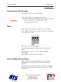
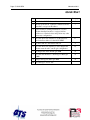
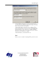
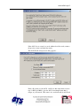
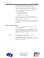
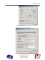
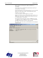
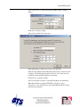
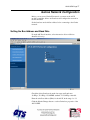
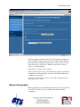
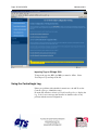
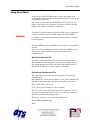
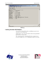
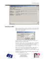
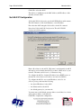
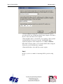
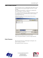
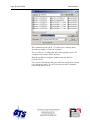
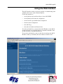
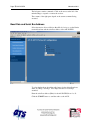
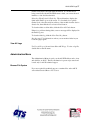
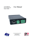
AN-X-GENI
Genius I/O
Communication
Module
User Manual
Page 2 AN-X-GENI
November 2011
Because of the variety of uses for the products described in this
publication, those responsible for the application and use of these
products must satisfy themselves that all necessary steps have been taken
to assure that each application and use meets all performance and safety
requirements, including any applicable laws, regulations, codes and
standards. In no event will Quest Technical Solutions be responsible or
liable for indirect or consequential damage resulting from the use or
application of these products.
Any illustrations, charts, sample programs, and layout examples shown
in this publication are intended solely for purposes of example. Since
there are many variables and requirements associated with any particular
installation, Quest Technical Solutions does not assume responsibility or
liability (to include intellectual property liability) for actual use based
upon the examples shown in this publication.
Throughout this manual we use notes to make you aware of safety
considerations.
Identifies information about practices or circumstances that can lead to
personal injury or death, property damage, or economic loss.
These warnings help to:
WARNING!
IMPORTANT!
TIP
•
identify a hazard
•
avoid the hazard
•
recognize the consequences
Identifies information that is especially important for successful
application and understanding of the product.
Identifies information that explains the best way to use the AN-X-GENI
Microsoft is a registered trademark of Microsoft Corporation.
Windows, Windows XP Windows Vista and Windows 7 are trademarks of Microsoft Corporation.
ControlLogix, RSLinx and RSLogix 5000 are trademarks of the Allen-Bradley Company, Inc.
AN-X-GENI MODULE OVERVIEW
2
Hardware Features
3
Package Contents
3
Other Requirements
3
Modes of Operation
3
INSTALLATION
4
Prevent Electrostatic Discharge
4
Power
4
Genius Cabling and Termination
4
Ethernet Cabling
5
Software Installation
5
QUICK START
6
ETHERNET CONFIGURATION
7
Ethernet Configuration
Example: Standalone Computer
7
12
Reconfiguring an AN-X from an Unknown State
16
GENIUS NETWORK CONFIGURATION
17
Setting the Bus Address and Baud Rate
17
Configuring the Genius Network
Autoconfiguration
18
18
Manual Configuration
19
Genius Configuration File Format
20
Viewing the Current Configuration
22
Saving the Current Configuration
22
Page 4 AN-X-GENI
November 2011
EXCHANGING SCHEDULED DATA WITH A CONTROLLOGIX
23
Mapping I/O Data
23
Other Mappable Data
Diagnostic Counters
Block Error Table
Block Fault Table
Connection Statistics
26
26
27
27
28
Viewing the Current Configuration
30
Saving the Current Configuration
31
Configuring the AN-X Module in RSLogix 5000
31
ControlLogix Tags
33
Using the ControlLogix Log
34
Using Ghost Mode
35
USING ANXINIT
37
AnxInit Log
37
Locating Available AN-X Modules
38
Selecting an AN-X
39
Set AN-X IP Configuration
40
Restart an AN-X
41
AN-X Info
41
Read Kernel Parameters
42
Run Config Mode
42
Update AN-X Flash
42
Update Firmware
Firmware Update Wizard
Update Firmware Command
43
43
47
Patch Firmware
47
USING THE WEB INTERFACE
49
Baud Rate and Serial Bus Address
50
Genius Network
51
Configure ControlLogix Support
52
View Configuration Files
52
View Active Configuration
53
Log Files
System Error Log
System Info Log
ControlLogix Log
Genius IO Fault Log
View All Logs
56
56
56
56
56
57
Administration Menu
Browse File System
AN-X IP Configuration
Archive Configuration
57
57
58
59
TROUBLESHOOTING
60
LEDs
Ethernet LEDs
SYS LED
NET LED – Network Status
Diagnostic Counters
60
60
60
61
61
UPDATING THE FIRMWARE
62
Reading Version Numbers
62
SPECIFICATIONS
63
SUPPORT
64
WARRANTY
65
AN-X-GENI Module Overview
The AN-X-GENI communications module connects a ControlLogix PLC
or other device to a Genius I/O network, over Ethernet.
The module supports scheduled connections with a ControlLogix
processor, over Ethernet, so the ControlLogix processor can read inputs
from the Genius network and write outputs.
The AN-X module acts as a scanner on the Genius network. It supports
up to 31 Genius blocks.
The AN-X-GENI module has a web interface for configuration. You can
communicate with the module using any standard web browser such as
Internet Explorer.
A watchdog timer is implemented in the module’s hardware. If the
firmware does not kick the watchdog within the timeout period the
watchdog times out and places the module into a safe fatal failure state.
The module firmware can be updated over Ethernet using the Windows
utility supplied. Refer to page 62 for details.
AN-X-GENI Page 3
Hardware Features
The module has:
•
LEDs to indicate the status of the connection to the Ethernet, the
module’s internal state, and state of the connection to the Genius
I/O network
•
an Ethernet connector
•
a power connector
•
a connector to connect to the Genius network
Package Contents
•
AN-X-GENI module
•
CD containing software and documentation
•
rubber feet for desktop use
Other Requirements
Genius handheld monitor to set the serial bus address for Genius blocks
and to configure blocks
Modes of Operation
There are three AN-X modes of operation:
•
Boot mode. The AN-X is running its low level startup firmware.
•
Configuration mode. This is the mode when you are updating the
firmware in the AN-X.
•
Production mode. This is the normal runtime mode of operation.
Page 4 AN-X-GENI
November 2011
Installation
Prevent Electrostatic Discharge
The module is sensitive to electrostatic discharge.
Electrostatic discharge can damage integrated circuits or
semiconductors. Follow these guidelines when you handle the module:
WARNING!
•
Touch a grounded object to discharge static potential
•
Do not touch the connector pins
Power
AN-X requires a DC power input of anywhere from 12 to 24 VDC.
Left to right the pins on the power connector are chassis ground, negative
voltage and positive voltage.
The chassis ground should be connected.
Power consumption internally is 250 mA @ 12VDC or 125 mA @
24VDC.
The part number for the power connector is Phoenix MSTB
2.5/3-ST-5.08
Contact QTS if you need a suitable wall adapter.
Genius Cabling and Termination
Refer to Genius I/O System and Communications User’s Manual,
GEK-90486F-1 for detailed information on Genius cabling and
installation.
The module has a 5-pin Phoenix connector for connection to the Genius
I/O network. The part number for the Genius bus connector is MSTB
2.5/5-ST-5.08
AN-X-GENI Page 5
Pin
Assignment
1
Not used
2
Shield out
3
Shield in
4
Serial 2
5
Serial 1
Ensure that the physical ends of the Genius I/O network are properly
terminated. The AN-X module does not have any internal termination.
WARNING!
Set the baud rate and serial bus address for the AN-X-GENI module
before connecting it to the Genius network.
Ethernet Cabling
AN-X has a standard RJ-45 connector for connecting to Ethernet.
If you are connecting AN-X to an existing network through a router or
switch, use a standard Ethernet cable.
If you are connecting directly between a computer and AN-X, use a
crossover cable.
Software Installation
You must uninstall any previous version of the software before you can
install a new version. Use the Windows Control Panel Add and Remove
Programs to remove the old version.
Insert the CD supplied with the AN-X module and run the program
setup.exe on the CD.
Page 6 AN-X-GENI
November 2011
Quick Start
Step
See page
1
Install the AN-X Windows software
5
2
Power up the AN-X, connect it to Ethernet and use
AnxInit to assign it an IP address
7
3
(Not needed for existing installations) Use the
Genius hand-held monitor to assign serial bus
addresses to Genius devices and perform any other
necessary configuration.
4
Use the AN-X web interface to set the baud rate
and serial bus address for the AN-X-GENI
17
5
Connect AN-X to the Genius network
4
6
Use the AN-X web interface to autoconfigure the
Genius network and ControlLogix configuration
18
7
Configure the AN-X in RSLogix 5000
31
8
Use the web interface to obtain tags for RSLogix
5000
33
9
Import the tags into RSLogix 5000
34
10
Use the tags to access data
AN-X-GENI Page 7
Ethernet Configuration
The AN-X-GENI module connects a computer or other device on
Ethernet to a Genius I/O network.
Before you can use the AN-X-GENI, you must configure its network
properties on Ethernet.
Ethernet Configuration
AN-X can be configured to use a static (unchanging) IP address or it can
be configured to obtain its IP address from a DHCP server.
Unless you have control of the DHCP server, in most applications you
will want to configure AN-X to use a static IP address. Otherwise the
DHCP server may assign a different IP address each time AN-X powers
up, and any software that accesses the AN-X module would have to be
reconfigured.
AN-X is shipped with DHCP enabled. If it finds a DHCP server on the
network, the DHCP server assigns it an IP address. You can use the
utility AnxInit to find the IP address that the DHCP server has assigned.
Select Utilities/Locate All AN-X Modules and AnxInit will locate the
AN-X and display its IP address.
If AN-X does not find a DHCP server within about three minutes of
starting up, it reverts to a temporary static IP address of 192.168.0.41 If
AN-X is using this temporary IP address, it repeatedly flashes the SYS
Page 8 AN-X-GENI
November 2011
LED three times followed by a pause. If your computer is on the same
subnet, you can use the web interface to change the IP address.
IMPORTANT!
Use this temporary IP address only for initial setup of AN-X. AN-X will
not function for its intended purpose at the temporary IP address.
If you are using multiple AN-X modules, configure one at a time,
especially if there is no DHCP server on the network, since they will all
revert to the same temporary IP address when they fail to find a DHCP
server.
IMPORTANT!
If you are connecting AN-X to an existing Ethernet network, consult the
network administrator to obtain a static IP address for AN-X and to
obtain information about how you should configure AN-X.
IMPORTANT!
The AN-X must be on the local Ethernet (same subnet) when you set its
IP address.
You configure the Ethernet properties using the Windows utility AnxInit
supplied with AN-X or the AN-X web interface.
Use the Configuration/AN-X IP Settings command to start the AN-X IP
configuration wizard, which takes you step by step through the IP
configuration process.
Step 1
In step 1, you identify the AN-X you are configuring.
AN-X-GENI Page 9
1. Select the Ethernet adapter that’s connected to the AN-X. In most
cases there will be just one Ethernet adapter in the computer. The AN-X
must be on the same subnet as the computer.
2. Enter the MAC address of the AN-X you are configuring. This is
printed on the AN-X label. It consists of six pairs of hexadecimal digits,
separated by hyphens. In the example above, it’s 00-0c-1a-00-00-09.
If the AN-X is already online, you can obtain its MAC address using the
Utilities/Locate All AN-X Modules command.
3. Enter the IP address you intend the AN-X to use.
Step 2
In step 2, you choose a method of restarting AN-X to put it in boot mode.
Page 10 AN-X-GENI
November 2011
The preferred method is to cycle power on the AN-X. Select the first
option on the screen and click the Next >> button.
An alternative method, useful if the AN-X in not easily accessible, is to
send it a command over Ethernet. The AN-X must be powered on and
completely running for this method to work. For example, if this is the
first time you are configuring a new AN-X, allow sufficient time for it to
acquire an IP address from a DHCP server or to time out and use its
default IP address (about 3 minutes). Select the second option on the
screen and click the Next >> button.
Step 3:
Wait for AN-X to enter boot mode. While AnxInit is waiting, the
Next>> button is disabled. When AN-X is in boot mode, the Next>>
button is enabled.
AN-X-GENI Page 11
If the AN-X does not enter boot mode within about 10 seconds, return to
the previous screens and check the entries.
The AN-X TCP/IP Configuration dialog appears.
Enter a Host Name for the AN-X. AN-X uses this name when it creates
tags for RSLogix 5000, so give the AN-X a meaningful name that is
unique on your network. This name is also used internally by AN-X and
Page 12 AN-X-GENI
November 2011
may be used to identify the AN-X if you have a DNS server on your
network. The name can be from 1 to 31 characters long.
To configure the AN-X to obtain its IP address from a DHCP server on
the network, select Obtain an IP address automatically (DHCP)
To configure the AN-X to use a static IP address, select Use the
following Settings and enter:
•
the desired IP address for the AN-X.
•
the Subnet mask for the AN-X
•
the default gateway for your network.
You must enter a default gateway address that is valid for the local
subnet even if there is no device at the gateway address on the network.
Click OK to complete the configuration.
If you Cancel the Configuration/AN-X IP Settings command, AN-X is
left running the boot code. Use the Utilities/Restart AN-X command to
restart the AN-X.
Example: Standalone Computer
Since you are connecting directly from the computer to AN-X, use a
crossover Ethernet cable.
The following instructions assume Windows 2000. The procedure for
Windows NT and Windows XP is very similar. They also assume that
an Ethernet network card has been installed in the computer and that
AnxInit has been installed on the computer.
TIP
The parameters in this example will work when you set up any
standalone computer to work with AN-X.
First configure the computer to use a static IP address. From the Start
menu, select Start/Settings/Network and Dialup Connections. Double
click on Local Area Connection.
AN-X-GENI Page 13
Click the Properties button.
Double click on Internet Protocol (TCP/IP).
Page 14 AN-X-GENI
November 2011
In this example, we will assign the computer an IP address of
192.168.0.10
Set the Subnet mask to 255.255.255.0 (standard mask for the Class C
network address of 192.168.0.x).
Set the Default gateway to 192.168.0.1 (this address does not exist on the
Ethernet network but AN-X requires a valid default gateway entry).
Click OK to accept the settings
Connect the computer to AN-X using the crossover cable.
If this is the first time you have used the AN-X module, it will look for a
DHCP server on the network. It waits about three minutes, then reverts
to a default IP address of 192.168.0.41
Power up the AN-X and wait for the search for a DHCP server to time
out. When the search for a DHCP server times out, AN-X will flash the
SYS LED red three times followed by a pause repeatedly.
Run AnxInit. Select Utilities/Locate All AN-X Modules and confirm that
it finds the AN-X.
AN-X-GENI Page 15
Select Utilities/Select An AN-X and enter the MAC Address and IP
address.
Click OK to accept the setting.
Select Utilities/AN-X IP Configuration.
Enter an IP Address. In this case we chose 192.168.0.20
Enter the same Subnet mask and Default gateway that you entered for the
computer. The default gateway address does not exist on the network
but AN-X requires that the field have a valid entry.
Click Finish to accept the settings.
Select Utilities/Restart AN-X to restart AN-X with the new parameters.
When the AN-X has restarted (SYS LED is solid green), select
Utilities/Locate All AN-X Modules and confirm that the AN-X is found
with the new parameters.
Page 16 AN-X-GENI
November 2011
Reconfiguring an AN-X from an Unknown State
It sometimes happens that an AN-X has been previously configured with
an IP address that causes it to be inaccessible on the current Ethernet
network. To reconfigure it to a known state, run the command
Configuration/AN-X IP Settings to start the AN-X IP Configuration
Wizard and reconfigure AN-X.
AN-X-GENI Page 17
Genius Network Configuration
Before you can scan a Genius I/O network, you must set the AN-X
module’s serial bus address and baud rate and configure the network in
the AN-X-GENI.
Set the baud rate and serial bus address before connecting to the Genius
network.
Setting the Bus Address and Baud Rate
From the AN-X web interface, select Automation Network/Genius
Baud/Node Settings.
Check the desired baud rate from the four supported baud rates:
38.4Kbps, 76.8 Kbps, 153.6 KBPS standard or 153.6 Kbps extended.
Enter the serial bus address (SBA) for the AN-X, in the range 1 to 31.
Click the Submit Changes button to set the Genius bus properties of the
AN-X-GENI.
Page 18 AN-X-GENI
November 2011
Configuring the Genius Network
There are two methods of configuring the Genius I/O that the
AN-X-GENI is to scan:
•
autoconfiguration. The AN-X-GENI reads the network contents by
sending messages to the attached network.
•
manual configuration. You build a configuration file and send it to
the AN-X-GENI.
You can also use autoconfiguration to build an initial configuration file,
edit the file to add features, then perform a manual configuration with the
modified file.
Autoconfiguration
Before you can perform an autoconfiguration, the Genius network must
be connected to the AN-X.
From the AN-X web interface, select Automation Network/Genius
Network Configuration.
AN-X-GENI Page 19
AN-X can generate a default ControlLogix data mapping configuration
based on the I/O it finds (see page 23). If you want to have it generate
the ControlLogix configuration, check Auto-configure Genius network
and ControlLogix configuration. Otherwise, check Auto-configure
Genius network (the default).
Click the Auto-configure Network button.
AN-X sends messages to all possible Genius bus addresses and builds a
configuration based on the replies it receives. AN-X then displays the
configuration it generated.
See page 22 for information on how to upload the configuration from
AN-X and save it to a file.
Manual Configuration
Manual configuration is useful when the Genius network is not attached
to the AN-X or when you need something other than the default
configuration.
Page 20 AN-X-GENI
November 2011
Create the configuration file using a text editor or a spreadsheet such as
Excel and save it as a comma separated variable (CSV) file, with
extension csv. The file format is described on page 20.
To send the configuration to AN-X:
1. From the AN-X web interface, select Automation Network/Genius
Network Configuration.
2. Type or browse the configuration file name into the Select file: area
3. Click the Send File To AN-X button to send the file to AN-X.
AN-X parses the file and displays either the current configuration if the
configuration was sent successfully or an error message if there was a
problem with the file.
Genius Configuration File Format
The Genius I/O configuration file defines the contents of the Genius
network to be scanned.
It is a comma-separated variable (csv) text file, which can be created
with a text editor or with a spreadsheet such as Excel.
Anything after a semicolon on a line is treated as a comment. Comments
can be inserted at the end of a line or on a separate line.
Genius Block Definitions
Each Genius block on the network is defined by a line in the
configuration file. The line contains various parameters that describe the
block.
Parameters are identified by keywords and are separated by commas.
Each definition begins with the parameter that defines the serial bus
address of the block being configured, for example, Block=7. The serial
bus address can be from 0 to 31.
The input length is defined by the keyword Inp= and can range from 0 to
128 bytes. If the input length definition is omitted, the input length
defaults to a length of 0.
The output length is defined by the keyword Out= and can range from 0
to 128 bytes. If the output length definition is omitted, the output length
defaults to a length of 0.
If the AN-X-GENI is to control the outputs on a module, include the
keyword Scan. If the AN-X-GENI is only to monitor the inputs on a
module, omit the keyword Scan.
The part number for a module is defined by the keyword Part= and can
be from 1 to 15 characters long. The part number text must be enclosed
in double quotes, for example Part="IC660BBD024".
AN-X-GENI Page 21
The description for a module is defined by the keyword Desc= and can
be from 1 to 95 characters long. The description text must be enclosed in
double quotes, for example Desc="12/24VDC 32 Ckt Source I/O Block".
The part number and description are used for comments only. You can
put whatever you want in them.
Each definition ends with the keyword EndBlock, which is required.
Parameter
Keyword
Valid entries
Serial bus address
Block=
0-31
Input length, bytes
Inp=
0-128
Output length, bytes
Out=
0-128
Scan mode
Scan
Scan
Part number
Part=
Maximum 15 characters, enclosed
in double quotes
Description
Desc=
Maximum 95 characters, enclosed
in double quotes
End of block
definition
EndBlock
Examples:
Block=0,Inp=0,Out=0,,Part="IC660HHM501",Desc="Hand-held Monitor",EndBlock
Block=1,Inp=2,Out=2,Scan,Part="IC660BBR101",Desc="16-Ckt Normally-open Relay
Block",EndBlock
When AN-X creates a Genius I/O configuration file after an
autoconfiguration, it inserts part numbers and descriptions from its
internal module database.
Global Data Sent by AN-X-GENI
If the AN-X-GENI is to send global data on the Genius network, add a
line of the form
GlobSend=length
to the configuration file. The length can be from 1 to 64. The length of
global data is in 16-bit words, not bytes.
Example:
GlobSend=4
Page 22 AN-X-GENI
November 2011
Sample Genius Configuration File
;QTS AN-X-GENI Scan Configuration Utility
;Copyright (c) 2005 Quest Technical Solutions
;Auto Config Geni I/O File
Block=0,Inp=0,Out=0,,Part="IC660HHM501",Desc="Hand-held Monitor",EndBlock
Block=1,Inp=2,Out=2,Scan,Part="IC660BBR101",Desc="16-Ckt Normally-open Relay
Block",EndBlock
Block=2,Inp=2,Out=2,Scan,Part="IC660BBD020",Desc="24/48VDC 16 Ckt Source I/O
Block",EndBlock
Block=3,Inp=8,Out=4,Scan,Part="IC660BBA020",Desc="24/48VDC 4In/2Out Analog
Block",EndBlock
Block=9,Inp=24,Out=24,Scan,Part="IC670GBI001",Desc="Genius Bus Interface
Unit",EndBlock
Block=16,Inp=64,Out=0,,Part="IC693BEM331",Desc="Series 90-30 Bus
Controller",EndBlock
Block=22,Inp=4,Out=4,Scan,Part="IC660BBD024",Desc="12/24VDC 32 Ckt Source I/O
Block",EndBlock
Block=31,Inp=64,Out=0,,Part="IC697BEM731",Desc="Series 90-70 Bus
Controller",EndBlock
GlobSend=24,; Global Data Sent by AN-X (16 bit words)
Viewing the Current Configuration
To view the Genius configuration currently in AN-X, access the web
interface and select Automation Network/View Active Configuration.
You can also view the configuration file by accessing the web interface
and selecting Automation Network/View Configuration Files. Click on
the AN-X-GENI Genius Network Configuration File link and select Open
to open the file in whatever application is associated with CSV files on
your computer, usually a spreadsheet or a text editor.
Saving the Current Configuration
To save the configuration currently in AN-X to a file, access the web
interface and select Automation Network/View Configuration Files.
Right click on the AN-X-GENI Genius Network Configuration File link
and save the file.
AN-X-GENI Page 23
Exchanging Scheduled Data with a ControlLogix
The AN-X-GENI supports multiple scheduled connections with a
ControlLogix processor over Ethernet.
The AN-X-GENI behaves like a 17-slot ControlLogix rack with an
ENBT/A module in slot 16 and generic modules in slots 0 to 15.
A ControlLogix processor can open a scheduled connection to each of
these 16 generic modules. Each scheduled connection consists of up to
248 words of output data from the ControlLogix processor to the AN-X
and up to 250 word of input data from the AN-X to the ControlLogix
processor.
Each connection can have a different RPI, from 5 to 750 ms.
In general, keep the number of connections small. There is significant
overhead in opening and maintaining each connection.
You map the inputs and outputs for the Genius blocks to these scheduled
connections. AN-X can create the mappings automatically or you can
create a mapping configuration manually.
You can let AN-X create a mapping file automatically, then edit the file
to better suit your application. For example, in order to make the most
efficient use of the available Ethernet bandwidth, you can organize the
data so that items that must update quickly are mapped to connections
with short RPIs and items that are less time critical are mapped to
connections with longer RPIs.
In addition, the AN-X module has diagnostic data that can be mapped to
ControlLogix scheduled input data.
Mapping I/O Data
You map Genius input and output data to the ControlLogix scheduled
data by creating a comma separated variable file that defines the
mappings and sending the file to the AN-X.
The file contains sections for each scheduled connection. Within each
scheduled connection are the definitions for the input and output data for
that connection. These definitions refer to the Genius module where the
data is to be found.
When you create a mapping for a Genius module, all the input or output
data for the module is mapped; you cannot map individual registers.
The file also contains options that apply to the whole configuration.
AN-X can automatically create a default mapping file when you
autoconfigure I/O. See page 18 for details.
Anything after a semicolon on a line is treated as a comment.
Page 24 AN-X-GENI
November 2011
ClxName
The first line in the file identifies the AN-X module. AN-X uses this
name in the address portion of the ControlLogix tags for the Genius data.
The ClxName consists of a line with the keyword ClxName, followed by
a comma and the name you give the emulated ENBT (see page 31)
Example:
ClxName, AnxGeniMas
ClxPrefix
The ClxPrefix is used in the alias names AN-X creates for import into
RSLogix 5000. AN-X prefixes each name with the ClxPrefix. The
ClxPrefix can be used to distinguish tags for the same Genius serial bus
address on different Genius networks when the ControlLogix processor
has connections to more than one AN-X-GENI.
For example, if the ControlLogix has connections to two AN-X-GENI
modules, each controlling a different Genius network, each Genius
network could have a block with the same serial bus address. Using a
different ClxPrefix in the configuration file for each AN-X-GENI makes
the tags for the two AN-X modules distinct.
The ClxPrefix consists of a line with the keyword ClxPrefix, followed by
a comma and the prefix text.
Example:
ClxPrefix,GENI1_
Scheduled Connections
Each scheduled connection to the AN-X begins with a line that consists
of the keyword ClxSlot followed by a comma and then a number from 0
to 15
Example:
ClxSlot, 0
Each scheduled connection consists of output data and input data.
The section that defines the scheduled outputs from the ControlLogix
processor for that connection begin with a line with just the keyword
DataOutput.
The section that defines the scheduled inputs to the ControlLogix
processor for that connection begin with a line with just the keyword
DataInput.
AN-X-GENI Page 25
Data definitions consist of lines that define the mapping between the
ControlLogix data table and the Genius module.
They consist of lines of the form
CLX_offset (optional), Genius_Location, tagname
The CLX_offset is the offset into the data for the connection. You can
select the offset where the data is located or you can leave it blank and
AN-X will automatically assign the offset.
The Genius_location consists of an address in the form bSBA where
SBA is the 2-digit serial bus address (SBA) of the module on the Genius
bus, from 1 to 31.
Example:
To associate ControlLogix offset 27 with the outputs from the Genius
module at serial bus address 4 and assign it tagname Block4Outputs, add
the following line to the DataOutput section of the connection
27, b4, Block4Outputs
Example:
To map the inputs from the Genius module at address 31 to the next
available ControlLogix location and assign it tagname Block31Inputs,
add the following line to the DataInput section of the connection
, b31, Block31Inputs
Global Data
To map the Global data sent by AN-X to the output data for a
connection, add the following line to the DataOutput section of the
connection:
GlobSend
AN-X obtains the length of the global data to map from the Genius I/O
configuration file (see page 21).
Program Mode Behaviour
The ControlLogix processor that is the exclusive owner of the connection
to the generic module in slot 0 controls how the AN-X-GENI module
scans the Genius network. For that reason, when you map the data, you
must always include a connection to the generic module in slot 0.
When the ControlLogix processor with the exclusive owner connection
to slot 0 on the AN-X is in program mode or the connection to slot 0 is
stopped or inhibited, the AN-X stops scanning the Genius network.
Page 26 AN-X-GENI
November 2011
Even if other ControlLogix processors have exclusive owner connections
to other slots on the AN-X and are in run mode, AN-X does not scan the
network.
You can override this behaviour by including a line with the keyword
ScanGeniProg in the configuration file. This causes the AN-X-GENI
module to continue to communicate with the Genius network when the
ControlLogix processor is in program mode but set all outputs to 0.
Similarly ControlLogix processors with exclusive owner connections to
other AN-X slots will also update. If the exclusive owner connection to
slot 0 stops, AN-X stops all communication with the Genius network.
WARNING!
This option is included for debugging since it allows inputs to update in
the ControlLogix. It should NOT be used in normal operation.
Other Mappable Data
In addition to the I/O data, there are other items that can be mapped to
connection input data.
If you create the ControlLogix configuration automatically when you
autoconfigure the Genius network, these items are mapped by default to
ClxSlot 15.
TIP
If you map the diagnostic data to a separate connection, use a long RPI
to reduce the Ethernet traffic, since the diagnostics do not need to be
updated as frequently as I/O data.
Diagnostic Counters
The AN-X-GENI maintains the following diagnostic counters.
Counter
Offset
Description
TxFrames
0
Transmitted network frames
TxMsgs
1
Transmitted network messages (datagrams)
RxFrames
2
Received network frames
RxMsgs
3
Received network messages (datagrams)
RxDup
4
Received duplicate frames
RxCrcErr
5
Received frames with a CRC error
RxStopErr
6
Received frames with a stop error
RxAbortErr
7
Received frames with an abort error
AN-X-GENI Page 27
Counter
Offset
Description
RxOverrunErr
8
Received frames with an overrun error
NoToken
9
No tokens received from network
To map the diagnostic counters, include a line with just the keyword
DiagCtrs in the input section of a connection. This maps all the
diagnostic counters (10 words); they cannot be mapped individually.
Block Error Table
The block error table consists of 2 16-bit words, one bit per serial bus
address. Bit 0 of the first word corresponds to serial bus address 0, bit 1
corresponds to serial bus address 1, and so on.
If a configured block is not active on the network, the bit is 1. If a
configured block is active on the network, the bit is 0. The bit is always
0 for an unconfigured block.
To map the block error table, include a line with just the keyword
BlockErr.
Example:
, BlockErr
TIP
Map the block error table to the beginning of input data of each
connection. If the connection to the AN-X module is lost, the
ControlLogix sets the first 2 words of the connection to FFFF
hexadecimal. If your program is monitoring the block error table, it will
see all the error bits as set.
Block Fault Table
A Genius block can generate fault messages for a variety of error
conditions. If the AN-X-GENI receives a fault message from a Genius
block, it sets the corresponding bit in the block fault table.
The block fault table consists to 2 16-bit words, one bit per serial bus
address. Bit 0 of the first word corresponds to serial bus address 0, bit 1
corresponds to serial bus address 1, and so on.
To map the block fault table, include a line with the keyword BlockFlt in
the input section of a connection.
Example:
,BlockFlt
If the block fault bit is set for a block, use the web interface on the
AN-X-GENI to view and clear the fault. Refer to page 56 for details.
Page 28 AN-X-GENI
November 2011
Connection Statistics
The module maintains statistics for each scheduled connection. In the
following table, O represents the connection originator (ControlLogix)
and T represents the connection target (AN-X).
The statistics for each connection consists of 10 words of data:
Offset
Description
0
Average time for last 100 O=>T updates
1
Minimum time for last 100 O=>T updates
2
Maximum time for last 100 O=>T updates
3
Maximum O=>T time since connection opened
4
Reserved
5
Average time for last 100 T=>O updates
6
Minimum time for last 100 T=>O updates
7
Maximum time for last 100 T=>O updates
8
Maximum T=>O time since connection opened
9
Reserved
The units for the times are 0.1 milliseconds. A value of 87 means 8.7
ms.
To map the statistics for a given connection, include a line with the
keyword ConnStatsn, where n is the connection number, from 0 to 16, in
the input section of a connection.
Example:
,ConnStats2
Values update at a rate equal to 100 times the RPI for the connection.
Averages are calculated for the last 100 updates.
Example Configuration File:
;QTS AN-X-GENI Scan Configuration Utility
;Copyright (c) 2005 Quest Technical Solutions
;Auto Config Ethernet/IP File
;ScanGeniProg
ClxName,AnxGeniMas
AN-X-GENI Page 29
ClxPrefix,GENI_
ClxSlot,0
DataOutput ; Outputs from ControlLogix
,b1,b01_Out, ; Ofs= 0 Len= 1 IC660BBR101 16-Ckt Normally-open Relay Block
,b2,b02_Out, ; Ofs= 1 Len= 1 IC660BBD020 24/48VDC 16 Ckt Source I/O Block
,b3,b03_Out, ; Ofs= 2 Len= 2 IC660BBA020 24/48VDC 4In/2Out Analog Block
,b9,b09_Out, ; Ofs= 4 Len=12 IC670GBI001 Genius Bus Interface Unit
,b22,b22_Out, ; Ofs= 16 Len= 2 IC660BBD024 12/24VDC 32 Ckt Source I/O Block
,GlobSend; Global Data Sent by AN-X-GENI
DataInput ; Inputs to ControlLogix
,BlockErr ; Map BlockErr here since Clx sets to -0xffffffff on Connection Failure
,b1,b01_Inp, ; Ofs= 2 Len= 1 IC660BBR101 16-Ckt Normally-open Relay Block
,b2,b02_Inp, ; Ofs= 3 Len= 1 IC660BBD020 24/48VDC 16 Ckt Source I/O Block
,b3,b03_Inp, ; Ofs= 4 Len= 4 IC660BBA020 24/48VDC 4In/2Out Analog Block
,b9,b09_Inp, ; Ofs= 8 Len=12 IC670GBI001 Genius Bus Interface Unit
,b16,b16_Inp, ; Ofs= 20 Len=32 IC693BEM331 Series 90-30 Bus Controller
,b22,b22_Inp, ; Ofs= 52 Len= 2 IC660BBD024 12/24VDC 32 Ckt Source I/O Block
,b31,b31_Inp, ; Ofs= 54 Len=32 IC697BEM731 Series 90-70 Bus Controller
;The following map 'Ghost Mode' Monitored Outputs to ClxSlot 8
;They must be 'uncommented' for 'Ghost Mode' Monitoring
;ClxSlot,8 ; This maps monitored 'Ghost Mode' outputs to Slot 8
;DataInput ; Inputs to ControlLogix
;,BlockErr ; Map BlockErr here since Clx sets to -0xffffffff on Connection Failure
;,m31>1[1],b01_OutMon, ; Ofs= 2 Len= 1 IC660BBR101 16-Ckt Normally-open Relay
Block
;,m31>2[1],b02_OutMon, ; Ofs= 3 Len= 1 IC660BBD020 24/48VDC 16 Ckt Source I/O
Block
;,m31>3[2],b03_OutMon, ; Ofs= 4 Len= 2 IC660BBA020 24/48VDC 4In/2Out Analog Block
;,m31>9[12],b09_OutMon, ; Ofs= 6 Len=12 IC670GBI001 Genius Bus Interface Unit
;,m31>22[2],b22_OutMon, ; Ofs= 18 Len= 2 IC660BBD024 12/24VDC 32 Ckt Source I/O
Block
;The following lines map Diagnostics into ClxSlot 15
ClxSlot,15
Page 30 AN-X-GENI
November 2011
DataInput ; Inputs to ControlLogix
0,BlockFlt, ; Ofs= 0 Len=2
10,DiagCtrs, ; Ofs= 10 Len=10
;ControlLogix Connection Statistics
,ConnStats0, ; Ofs= 20 Len=10
Viewing the Current Configuration
To view the ControlLogix configuration currently stored in the AN-X,
start the web interface and select View Active Configuration.
Click the Ethernet/IP link to view the current ControlLogix scheduled
data configuration.
AN-X-GENI ControlLogix Config File /home/axctrl/GeniEnetIpSvr.csv
5: ;DisOutOnProg
7: ClxExp: AnxGeniMas
8: ClxPrefix: GENI_
9: ClxSlot 0
11: DataOutput
12: 0 1 b01 b01_Out 16-Ckt Normally-open Relay Block
13: 1 1 b02 b02_Out 24/48VDC 16 Ckt Source I/O Block
14: 2 2 b03 b03_Out 24/48VDC 4In/2Out Analog Block
15: 4 12 b09 b09_Out Genius Bus Interface Unit
16: 16 2 b22 b22_Out 12/24VDC 32 Ckt Source I/O Block
21: DataInput
22: 0 2 BlockErr
23: 2 1 b01 b01_Inp 16-Ckt Normally-open Relay Block
24: 3 1 b02 b02_Inp 24/48VDC 16 Ckt Source I/O Block
25: 4 4 b03 b03_Inp 24/48VDC 4In/2Out Analog Block
26: 8 12 b09 b09_Inp Genius Bus Interface Unit
27: 20 8 b16 b16_Inp Series 90-30 Bus Controller
28: 28 2 b22 b22_Inp 12/24VDC 32 Ckt Source I/O Block
29: 30 64 b31 b31_Inp Series 90-70 Bus Controller
48: ClxSlot 15
50: DataInput
51: 0 2 BlockFlt
AN-X-GENI Page 31
52: 10 10 DiagCtrs
55: 20 10 ConnStats0
......Parse Successful
Each line begins with a line number, from the original ControlLogix
configuration file. Each mapping line shows the offset and length of the
data in the ControlLogix data connection.
Saving the Current Configuration
To save the ControlLogix configuration currently stored in the AN-X to
a file, start the web interface and select Automation Network/View Active
Configuration.
Right click the Ethernet/IP link and select Save target to save the current
ControlLogix scheduled data configuration to a file.
You can also save the ControlLogix configuration by selecting
Automation Network/View Configuration Files. Right click on the
AN-X-GENI ControlLogix Configuration File link and select Save target
to save the current ControlLogix scheduled data configuration to a file.
Configuring the AN-X Module in RSLogix 5000
To configure the AN-X-GENI in RSLogix 5000:
1. Right click on the ControlLogix Ethernet module that will be
communicating to the AN-X and select Add Module. Add a
1756-ENBT/A module. Set the Major Rev to 1.
Page 32 AN-X-GENI
November 2011
Set the Name to match the hostname of the AN-X in the Ethernet
configuration.
Set the Slot to 16. Set the chassis size to 17.
Set the Comm Format to None.
Set the IP address to match the AN-X module.
Set Electronic Keying to Disable Keying.
2. Add Generic modules for each required connection
Set the parameters as shown. Set the Slot to 0 for the first connection, 1
for the second connection, and so on.
3. Set the RPI for each connection.
AN-X-GENI Page 33
IMPORTANT!
Ensure that any check box that refers to Unicast connections is
unchecked.
ControlLogix Aliases
AN-X uses the Ethernet/IP configuration to create aliases that can be
imported into RSLogix 5000. Use these alias tags in your RSLogix 5000
program to access the data on the AN-X.
There are two sets of tag files, one for exclusive owner connections and
one for input only connections.
In the web interface, select Automation Network/View Configuration
Files.
To view the files, click either AN-X-GENI Ethernet/IP ControlLogix
Exclusive Owner Data Tags or AN-X-GENI Ethernet/IP ControlLogix
Input Only Data Tags.
To save the file to your computer, right click on the link and select Save
Target As…
Page 34 AN-X-GENI
November 2011
Importing Tags in RSLogix 5000
To import the tags into RSLogix 5000, you must be offline. Select
Tools/Import Tags and import the file.
Using the ControlLogix Log
If there are problems with scheduled connections to the AN-X, use the
ControlLogix log to identify the cause.
From the web interface, select Log Files/ControlLogix Log to display the
log. Look for error messages that describe in detail the cause of any
problem with the current configuration.
AN-X-GENI Page 35
Using Ghost Mode
In ghost mode, the AN-X-GENI monitors inputs and outputs on an
existing Genius network and passes the monitored data to a ControlLogix
via scheduled connections.
Ghost mode is useful when the AN-X-GENI and a ControlLogix is to
replace an existing control system and you want to verify the data and
timing on the existing system before replacing it.
WARNING!
You must be careful in setting up ghost mode that you do not disrupt the
existing sytem when you connect and configure the AN-X-GENI
Configuration is best performed when the existing system is connected
but is not running.
The AN-X-GENI requires an available serial bus address on the Genius
network.
You can use the autoconfiguration feature of the AN-X-GENI to locate
all the devices on the network and generate a starting Genius
configuration file.
Genius Configuration File
You must configure the Genius I/O on the network being monitored.
The configuration file format is the same as described earlier (see page
20). Ensure that the Scan field is removed from all Genius devices so
that the AN-X-GENI doesn’t write outputs to the network
ControlLogix Configuration File
The output data on the Genius network is mapped to ControlLogix
scheduled inputs.
Data definitions for the monitored outputs consist of lines that define the
mapping of the Genius output data into the ControlLogix data table.
They consist of lines of the form
CLX_offset (optional), Genius_Location, tagname
The CLX_offset is the offset into the data for the connection. You can
select the offset where the data is located or you can leave it blank and
AN-X will automatically assign the offset.
The Genius_location consists of an address in the form
msourceSBA>destSBA[length]
where
Page 36 AN-X-GENI
November 2011
sourceSBA is the serial bus address (SBA) of the module on the Genius
bus that is sending the data
destSBA is the serial bus address of the destination
length is the length of data in words
Genius bus input data is mapped as before.
Example:
A Genius bus controller at serial bus address 31 is sending 2 words of
output data to a Genius block at serial bus address 17. To map this data
to a offset 27 in a ControlLogix scheduled connection, and assign it
tagname Block17Outputs, add the following line to the DataInput section
of the connection
27, m31>17[2], Block17Outputs
ControlLogix Tags
As before, AN-X can create tags that can be imported into RSLogix 5000
to access the data.
Quick Start
Use the following steps to run the AN-X-GENI in ghost mode.
1. Use the web interface to set the baud rate and serial bus address
2. Connect AN-X-GENI to the Genius network.
3. Use the web interface to perform an autoconfiguation and
automatically generate a ControlLogix configuration.
4. Save and edit the Genius configuration file. Remove Scan from all
network devices.
5. Save and download the modified Genius configuration file to the
AN-X-GENI.
6. Save and edit the ControlLogix confguration file the AN-X-GENI
created when you performed the autoconfiguration. Comment out all
the DataOutput sections. Uncomment the ghost mode entries it
created and modify them to suit your application.
7. Save and download the modified ControlLogix configuration file.
8. Use the web interface to view the active configuration and locate the
data.
9. Use the web interface to export the tags for the ControlLogix
configuration and import them into RSLogix 5000.
10. Use the tags to access the data from RSLogix 5000.
AN-X-GENI Page 37
Using AnxInit
AnxInit is a 32-bit Windows application supplied with AN-X to perform
the following functions:
•
Locate and identify AN-X modules on the Ethernet network
•
Select a specific AN-X for configuration
•
Set the IP address and other network parameters for an AN-X
•
Restart an AN-X
•
Display information about the selected AN-X
•
Read the kernel parameters for the selected AN-X
•
Update the flash (low level firmware) on the selected AN-X
•
Update the firmware on the selected AN-X
•
Patch the firmware on the selected AN-X
In addition, it can be used to:
•
clear the AnxInit log
•
copy the contents of the log to the clipboard for use by another
application. This is often useful for technical support
AnxInit Log
AnxInit logs messages in its main window. These messages are often
useful for determining the cause of errors or for technical support.
To clear the log, select Edit/ClearLog.
To copy the contents of the Log to the Windows clipboard so that they
can be pasted into another application, select Edit/Copy.
Page 38 AN-X-GENI
November 2011
AN-X Log
Locating Available AN-X Modules
To locate all accessible AN-X modules on the Ethernet network, select
Utilities/Locate All AN-X Modules.
AnxInit displays a list of the AN-X modules it finds, showing their MAC
IDs, IP addresses and host names.
This command is useful for determining IP addresses when they have
been set by a DHCP server or for confirming that an AN-X is accessible.
AN-X-GENI Page 39
Selecting an AN-X
Before you can perform an operation on an AN-X, you must select which
AN-X you want the operation performed on. Choose Utilities/Select An
AN-X to select a specific AN-X.
From the Adapter list, select the network adapter that connects to the
Ethernet network that contains the AN-X.
In the Ethernet MAC Address field, enter the MAC Address of the AN-X
you wish to select. It can be found on the AN-X label or using the
Locate All AN-X Modules command. The format is as shown above, six
pairs of hexadecimal digits separated by hyphens.
In the IP Address field, enter the Ethernet IP address of the AN-X you
wish to select. It can be found using the Locate All AN-X Modules
command. The format is as shown above, four decimal numbers, each in
the range 0 to 255.
Both MAC address and IP address must match the settings on the AN-X
in order for communication to occur.
Page 40 AN-X-GENI
November 2011
Click OK to select the AN-X.
The title bar of AnxInit shows the MAC Address and IP Address of the
currently selected AN-X.
Set AN-X IP Configuration
Utilities/AN-X IP Configuration sets the AN-X IP address and hostname.
The AN-X must be on the local Ethernet to set its IP address.
First select the AN-X using the Utilities/Select An AN-X command.
Next select Utilities/AN-X IP Configuration. The AN-X TCP/IP
Configuration dialog appears.
Enter a Host Name for the AN-X. This name is used internally by AN-X
and may be used to identify the AN-X if you have a DNS server on your
network. The name can be from 1 to 31 characters long.
To configure the AN-X to obtain its IP address from a DHCP server on
the network, select Obtain an IP address automatically (DHCP)
To configure the AN-X to use a static IP address, select Use the
following Settings and enter the following:
•
the desired IP address for the AN-X.
•
the Subnet mask for the AN-X
•
the default gateway for your network.
You must enter a valid default gateway address even if there is no device
at the gateway address on the network.
Click OK to complete the configuration.
AN-X-GENI Page 41
Utilities/AN-X IP Configuration resets the selected AN-X. Use the
Utilities/Restart AN-X to restart the AN-X in production mode.
If you Cancel the Utilities/AN-X IP Configuration command, AN-X is
left running the boot code. Use the Utilities/Restart AN-X command to
restart the AN-X.
Restart an AN-X
Use the Utilities/Restart AN-X command to restart the currently selected
AN-X.
AN-X Info
The Utilities/AN-X Info command provides information about the
currently selected AN-X in the log window.
The information shown:
AN-X Info
Ethernet MAC address
SerNum
Serial number
DaughterID
Daughterboard ID, 0b hex for AN-X-GENI
BootRev
Boot code version
ConfigRev
Configuration kernel version
ProdRev
Production kernel version
HwRev
Hardware version
FirmwRev
Firmware release version (depends on current
operating mode)
Status
see below
VendorId
Vendor ID
ProdId
Product ID (0E hex, 14 decimal)
IpAddrStr
IP address assigned using Utilities/AN-X IP
Configuration
HostName
name assigned using Utilities/AN-X IP
Configuration
In boot mode, FirmwRev, Vendor ID and Product ID and not valid, and
IpAddrStr and HostName are not shown.
Page 42 AN-X-GENI
November 2011
Possible status values are:
Value
Meaning
1
Boot mode
2
Configuration mode
4
Production mode
Read Kernel Parameters
The Utilities/Read Kernel Parameters command displays various
communications parameters for the currently selected AN-X
This command resets the AN-X. You will be warned and given the
opportunity to cancel the command.
The Utilities/Read Kernel Parameters command leaves the AN-X
running the boot code. Use the Utilities/Restart AN-X command to
restart the AN-X in production mode.
Run Config Mode
The Utilities/Run Config Mode command is used to restart the currently
selected AN-X in configuration mode (normally used internally for
updating firmware).
This command is not used in normal operation but may be required for
technical support.
The AN-X is in configuration mode when the SYS LED flashes red
twice, followed by a pause.
To exit configuration mode, use the Utilities/Restart AN-X command to
restart AN-X in production mode.
Update AN-X Flash
The Utilities/Update AN-X Flash command updates the low-level
firmware (configuration and production kernels).
Files have extension qtf.
AN-X-GENI Page 43
This command resets the AN-X. You will receive a warning and be
given the opportunity to Cancel the command.
If you cancel at the filename dialog, the AN-X has already been reset and
is in boot mode. Use the Utilities/Restart AN-X command to restart it in
production mode.
Update Firmware
There are two ways to update all the firmware in an AN-X module.
1. The Configuration/Firmware Update command starts the firmware
update wizard, which takes you step by step through the firmware
update process.
2. The Utilities/Update Firmware command updates all the firmware
on an AN-X you have selected using the Utilities/Select An AN-X
command.
Firmware files have extension bin.
Firmware Update Wizard
Select the Configuration/Firmware Update command to start the
firmware update wizard.
Step 1:
In step 1, you identify the AN-X you are configuring.
Page 44 AN-X-GENI
November 2011
1. Select the Ethernet adapter that’s connected to the AN-X. In most
cases there will be just one Ethernet adapter in the computer. The AN-X
must be on the same subnet as the computer.
2. Enter the MAC address of the AN-X you are updating. This is printed
on the AN-X label. It consists of six pairs of hexadecimal digits,
separated by hyphens. In the example above, it’s 00-0c-1a-00-00-09.
If the AN-X is already online, you can obtain its MAC address using the
Utilities/Locate All AN-X Modules command.
3. Enter the IP address of the AN-X you want to update
Step 2
In step 2, you choose a method of restarting AN-X to put it in config
mode.
AN-X-GENI Page 45
The preferred method is to cycle power on the AN-X. Select the first
option on the screen and click the Next >> button.
The second method, useful if the AN-X in not easily accessible, is to
send it a command over Ethernet. The AN-X must be powered on and
completely running for this method to work. For example, if this is the
first time you are configuring a new AN-X, allow sufficient time for it to
acquire an IP address from a DHCP server or to time out and use its
default IP address (about 3 minutes). Select the second option on the
screen and click the Next >> button.
Step 3:
Wait for AN-X to enter config mode. While AnxInit is waiting, the
Next>> button is disabled. When AN-X is in boot mode, the Next>>
button is enabled.
Page 46 AN-X-GENI
November 2011
If the AN-X does not enter config mode within about 60 seconds, return
to the previous screens and check the entries.
Click the Next>> button, and select the firmware file you want to
download and click Open.
AnxInit transfers the firmware file and restarts the AN-X.
After you update the firmware, you must reconfigure the AN-X.
AN-X-GENI Page 47
Update Firmware Command
The Utilities/Update Firmware command updates all the firmware on an
AN-X you have previously selected using the Utilities/Select An AN-X
command.
This command resets the AN-X. You will receive a warning and be
given the opportunity to Cancel the command.
If you cancel at the filename dialog, the AN-X has already been reset and
is in configuration mode. Use the Utilities/Restart AN-X command to
restart it in production mode.
Click the Next>> button, and select the firmware file you want to
download and click Open.
AnxInit transfers the firmware file and restarts the AN-X.
After you run update the firmware, you must reconfigure the AN-X.
Patch Firmware
The Utilities/Patch Firmware command applies small patches to the
firmware running on the AN-X.
These patch files files have extension pch.
Page 48 AN-X-GENI
November 2011
This command resets the AN-X. You will receive a warning and be
given the opportunity to Cancel the command.
You do not have to reconfigure the AN-X after applying a patch. All
configuration information will be left intact.
When the patch has been applied, AnxInit restarts the AN-X in
production mode.
If you cancel at the filename dialog, the AN-X has already been reset and
is in configuration mode. Use the Utilities/Restart AN-X command to
restart it in production mode.
AN-X-GENI Page 49
Using the Web Interface
The AN-X module contains a webserver capable of communicating with
standard web browsers such as Internet Explorer.
Use the web interface to:
•
set the baud rate and serial bus address for the AN-X-GENI
•
set the Genius bus I/O network configuration
•
set the ControlLogix scheduled data configuration
•
view the current configuration
•
view AN-X logs
•
view and clear faults from Genius blocks
To use the web interface, you need to know the IP address of the AN-X.
Use the Utilities/Locate All AN-X Modules command in AnxInit to find
all AN-X modules on the Ethernet network.
To access the web interface, start your web browser and type the AN-X
IP address where you normally enter web addresses in the browser.
Page 50 AN-X-GENI
November 2011
The left pane contains commands. Click on the arrows at the left of the
main headings to expand or contract the sections.
The contents of the right pane depend on the current command being
executed.
Baud Rate and Serial Bus Address
Select Automation Network/Genius Baud/Node Settings to set the Genius
network baud rate and the serial bus address of the AN-X-GENI.
To select the baud rate, check the radio button for the desired baud rate,
either 38.4 Kbps, 76.8 Kbps, 153.6 Kbps Standard or 153.6 Kbps
extended.
Enter the serial bus address (SBA) for the AN-X-GENI, from 1 to 31.
Click the SUBMIT button to send the values to the AN-X.
AN-X-GENI Page 51
Genius Network
Select Automation Network/Genius I/O Network Configuration to
configure the I/O the AN-X-GENI is to scan.
Autoconfiguration
If you are autoconfiguring the Genius network, connect the Genius
network to the AN-X-GENI.
To configure just the I/O, check Auto-configure Genius network.
To configure the Genius network and also generate a default
ControlLogix configuration on the AN-X, check Auto-configure Genius
network and ControlLogix configuration
Click the Auto-configure Network button.
Manual Configuration
Manual configuration does not require that the network be online.
Create a configuration file. Refer to page 23 for details on the file
format.
Page 52 AN-X-GENI
November 2011
Browse or type the file name.
Click the Send File to AN-X button to send the values to AN-X.
Configure ControlLogix Support
AN-X exchanges scheduled data with a ControlLogix processor over
Ethernet. Refer to section Exchanging Scheduled Data with a
ControlLogix on page 23 for information on configuring scheduled data
exchange.
Select Automation Network/Configure ControlLogix Support in the web
interface to upload the configuration.
Type or browse the configuration file name into the Select file: area.
Then click the Send To AN-X button to send the file to AN-X.
Check the ControlLogix Log to determine if there have been any errors
with the upload.
AN-X-GENI Page 53
View Configuration Files
Select View Configuration Files to view the Genius and ControlLogix
configuration files.
Click on the links to view the files using the application that is associated
with CSV files.
Right click on the links to retrieve the files from AN-X and store them on
your computer.
View Active Configuration
Select View Active Configuration to view the Genius or ControlLogix
configuration file in the web browser.
Click the Genius network link to view the current Genius network
configuration.
Page 54 AN-X-GENI
November 2011
Click the Ethernet/IP link to view the current ControlLogix
configuration.
AN-X-GENI Page 55
Page 56 AN-X-GENI
November 2011
Log Files
AN-X maintains various logs to record diagnostic and error messages.
Use the Log Files menu in the web interface to view these logs.
System Error Log
The System Error log records errors that occur during AN-X operation.
This log is normally empty.
System Info Log
The System Info Log records informational messages during startup and
normal operation.
ControlLogix Log
The Ethernet/IP log shows messages and errors associated with the
ControlLogix scheduled data operation.
Genius IO Fault Log
AN-X-GENI Page 57
Genius bus modules can return fault information. If a module that is
being controlled by the AN-X-GENI returns a fault, you can use the web
interface to view and clear the fault.
Select Log Files/Genius IO Fault Log. The web interface displays the
faults in the Fault Log are of the screen. To clear faults for a specific
Genius block, select the serial bus address of the module from the Station
Number list, then click the Clear Station Faults button.
To clear the faults on all modules, click the Clear All Faults button.
If there is a problem clearing faults, an error message will be displayed in
the Fault Log area.
To clear the fault log, click the Clear Fault Log button.
See also page 27 for information on how you can monitor faults in your
ControlLogix program.
View All Logs
Use View All Logs to list and view all the AN-X logs. To view a log file,
double click on the file name.
Administration Menu
The Administration Menu is used to set the AN-X IP address and to view
and edit files on AN-X. The file edit function is password protected and
is used only for AN-X technical support.
Browse File System
If you are required by technical support to examine files on the AN-X,
select Administration/Browse File System.
Page 58 AN-X-GENI
November 2011
Technical support will provide the password and supply detailed
information on any further steps.
AN-X IP Configuration
You can change the AN-X IP configuration from the web interface. This
requires that you already know the currect IP address and can use it to
access the web interface.
Select Administration/AN-X IP Configuration.
AN-X-GENI Page 59
You can configure the AN-X to use DHCP or to use a static IP address.
Click SUBMIT to set the parameters.
When prompted, click CONTINUE to reboot the AN-X with the new
parameters.
Archive Configuration
You can archive all the current AN-X configuration files and log files
from the web interface. The archive file is a standard gzip compressed
tar archive.
Select Administration/Archive configuration.
Click on the Archive File link and save the file. Select the destination
where the file will be stored.
Page 60 AN-X-GENI
November 2011
Troubleshooting
LEDs
The AN-X-GENI has LEDs that indicate the state of the Ethernet
connection, the overall module state and the connection to the Genius
network.
Ethernet LEDs
There are two LEDs that indicate the state of the Ethernet connection.
The orange LED, labelled 100, is on if the link is running at 100
Mbits/second and is off otherwise.
The green Link/Act LED is off if the link is inactive and is on if the link
is active. If activity is detected, the link blinks at 30 ms intervals and
continues blinking as long as activity is present.
SYS LED
The SYS LED is used by the AN-X operating system and software to
indicate the state of operations and errors. Errors or status indication in
boot mode cause the LED to flash yellow. In the other modes, the LED
flashes red.
The SYS LED should be used in conjunction with the logs to locate the
cause of problems.
In the following, red 3 means three red flashes followed by a pause, and
so on.
SYS LED State
Possible cause
Red 2
AN-X is in config mode
Red 3
DHCP configuration failed
Red 4
Fatal application error, check logs for cause
Red 5
Application memory access violation, check logs
Red 6
Application failed, illegal instruction, check logs
Red 7
Application crashed, unknown cause, check logs
Fast red flash
Reconfiguration (set station number and baud
rate) failed
Single red flash
Unscheduled messaging, addressing or
connection problem
Slow red flash
Script or application problem during startup
AN-X-GENI Page 61
At startup, the SYS LED sequence is:
•
boot code starts – fast flashing red
•
boot code loads a kernel – solid red
•
if the configuration kernel is loaded, 2 red flashes followed by a
pause
•
if the production kernel loads with no errors, solid green
NET LED – Network Status
The NET LED indicates the status of the Genius network connection.
Solid green
All configured blocks are active on the Genius bus
Some blocks may be in error
Yellow
No configured Genius I/O, and no Genius network
activity
Flashing or
solid red
One or more configured Genius blocks is not active on
the network
Network error (CRC, stop, abort, etc.)
Baud rate mismatch
Diagnostic Counters
Map the diagnostic counters to the ControlLogix data and check the error
counters.
Page 62 AN-X-GENI
November 2011
Updating the Firmware
The AN-X operating software consists of several parts:
•
boot code, runs at startup
•
configuration kernel, runs when you update firmware
•
production kernel, runs in normal operation
•
application software, for Genius network communication and
scheduled messaging
The kernels are supplied in files with extension qtf and are updated using
the AnxInit utility. Run the command Utilities/Update AN-X Flash and
select the file you wish to download. Refer to page 42 for details.
Firmware files contain the application programs for AN-X and have
extension bin. They are downloaded using the command
Configuration/Firmware Update or Utilities/Update Firmware in
AnxInit. Refer to page 43 for details.
Occasionally individual patch files are released. They have extension pch
and are downloaded using the Utilities/Patch Firmware command in
AnxInit. Refer to page 47 for details.
Reading Version Numbers
To read the version numbers of the various software components:
Boot code
AnxInit – AN-X Info
Configuration kernel
AnxInit – AN-X Info
Production kernel
AnxInit – AN-X Info
Firmware
AnxInit – AN-X Info (version depends on
current mode, boot, configuration or
production)
Individual applications
Web interface, System Info Log
AN-X-GENI Page 63
Specifications
Parameter
Specification
Function
Bridge between Ethernet/IP and Genius
network
Typical Power
Consumption
250 mA @ 12 VDC or 125 mA @ 24 VDC
Maximum Power
dissipation
3.0W
Environmental
Conditions:
Operational
Temperature
0-50°C (32-122°F)
Storage Temperature
–40 to 85°C (–40 to 185°F)
Relative Humidity
5-95% without condensation
Page 64 AN-X-GENI
November 2011
Support
How to Contact Us: Sales and Support
Sales and Technical Support for this product are provided by ProSoft
Technology. Contact our worldwide Sales or Technical Support teams
directly by phone or email:
Asia Pacific
+603.7724.2080, [email protected]
Europe – Middle East – Africa
+33 (0) 5.34.36.87.20, [email protected]
North America
+1.661.716.5100, [email protected]
Latin America (Sales only)
+1.281.298.9109, [email protected]
AN-X-GENI Page 65
Warranty
Quest Technical Solutions warrants its products to be free from defects
in workmanship or material under normal use and service for three years
after date of shipment. Quest Technical Solutions will repair or replace
without charge any equipment found to be defective during the warranty
period. Final determination of the nature and responsibility for defective
or damaged equipment will be made by Quest Technical Solutions
personnel.
All warranties hereunder are contingent upon proper use in the
application for which the product was intended and do not cover
products which have been modified or repaired without Quest Technical
Solutions approval or which have been subjected to accident, improper
maintenance, installation or application, or on which original
identification marks have been removed or altered. This Limited
Warranty also will not apply to interconnecting cables or wires,
consumables nor to any damage resulting from battery leakage.
In all cases Quest Technical Solutions’ responsibility and liability under
this warranty shall be limited to the cost of the equipment. The purchaser
must obtain shipping instructions for the prepaid return of any item under
this Warranty provision and compliance with such instruction shall be a
condition of this warranty.
Except for the express warranty stated above Quest Technical Solutions
disclaims all warranties with regard to the products sold hereunder
including all implied warranties of merchantability and fitness and the
express warranties stated herein are in lieu of all obligations or liabilities
on the part of Quest Technical Solutions for damages including, but not
limited to, consequential damages arising out of/or in connection with
the use or performance of the Product.