1
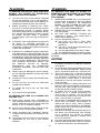
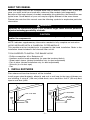
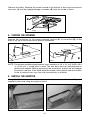
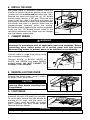
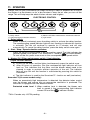
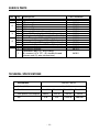
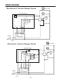
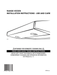
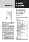
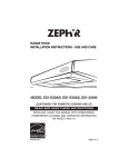
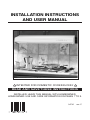
INSTALLATION INSTRUCTIONS
AND USER MANUAL
HB0018
!
INTENTED FOR DOMESTIC COOKING ONLY
!
READ AND SAVE THESE INSTRUCTIONS
INSTALLER: LEAVE THIS MANUAL WITH HOMEOWNER.
HOMEOWNER: USE AND CARE INFORMATION ON PAGES 7 TO 9.
04741
rev. C
!
WARNING
!
TO REDUCE THE RISK OF FIRE, ELECTRIC
SHOCK, OR INJURY TO PERSON(S)
OBSERVE THE FOLLOWING:
1.
Use this unit only in the manner intended
by the manufacturer. If you have questions,
contact the manufacturer at the address or
telephone number listed in the warranty.
2.
Before servicing or cleaning unit, switch
power off at service panel and lock service
disconnecting means to prevent power
from being switched on accidentally. When
the service disconnecting means cannot
be locked, securely fasten a prominent
warning device, such as a tag, to the service
panel.
3.
Installation work and electrical wiring must
be done by qualified personnel in
accordance with all applicable codes and
standards, including fire-rated construction
codes and standards.
4.
Sufficient air is needed for proper combustion
and exhausting of gases through the flue
(chimney) of fuel burning equipment to prevent
backdrafting. Follow the heating equipment
manufacturer’s guidelines and safety standards
such as those published by the National
Fire Protection Association (NFPA), and
the American Society for Heating,
Refrigeration and Air Conditioning
Engineers (ASHRAE), and the local code
authorities.
5.
When cutting or drilling into wall or ceiling,
do not damage electrical wiring and other
hidden utilities.
6.
Ducted fans must always be vented to the
outdoors.
7.
Do not use this unit with any solid-state
speed control device.
8.
To reduce the risk of fire, use only steel
ductwork.
9.
This unit must be grounded.
1.
SMOTHER FLAMES with a close-fitting lid,
cookie sheet, or metal tray, then turn off the
burner. BE CAREFUL TO PREVENT
BURNS. IF THE FLAMES DO NOT GO
OUT IMMEDIATELY, EVACUATE AND
CALL THE FIRE DEPARTMENT.
2. NEVER PICK UP A FLAMING PAN – You
may be burned.
3. DO NOT USE WATER, including wet
dishcloths or towels – This could cause a
violent steam explosion.
4. Use an extinguisher ONLY if:
A. You know you have a Class ABC
extinguisher and you know how to
operate it.
B. The fire is small and contained in the
area where it started.
C. The fire department has been called.
D. You can fight the fire with your back to an exit.
* Based on “Kitchen Fire Safety Tips” published
by NFPA.
CAUTION
1.
2.
3.
4.
5.
TO REDUCE THE RISK OF A RANGE TOP
GREASE FIRE:
a)
Never leave surface units unattended at
high settings. Boilovers cause smoking and
greasy spillovers that may ignite. Heat oils
slowly on low or medium settings.
b) Always turn hood ON when cooking at high
heat or when cooking flaming foods.
c)
Clean ventilating fans frequently. Grease
should not be allowed to accumulate on fan
or filter.
d) Use proper pan size. Always use cookware
appropriate for the size of the surface
element.
WARNING
TO REDUCE THE RISK OF INJURY TO
PERSON(S) IN THE EVENT OF A RANGE
TOP GREASE FIRE, OBSERVE THE
FOLLOWING*:
6.
7.
8.
9.
-2-
For general ventilating use only. Do not use
to exhaust hazardous or explosive materials
and vapors.
To avoid motor bearing damage and noisy
and/or unbalanced impellers, keep drywall
spray, construction dust, etc. of power unit.
Your hood motor has a thermal overload
which will automatically shut off the motor
if it becomes overheated. The motor will
restart when it cools down. If the motor
continues to shut off and restart, have the
hood serviced.
For best capture of cooking impurities, the
bottom of the hood should be a minimum of
20” (24” over a gas range) and a maximum
of 30” above the cooking surface.
To reduce the risk of fire and to properly
exhaust air on a ducted installation, be
sure to duct air outside – Do not exhaust
air into spaces within walls or ceiling or into
attics, crawl spaces, or garage.
This product is equipped with a thermostat
which may start blower automatically. To
reduce the risk of injury and to prevent
power from being switched on accidentally,
switch power off at service panel and lock
or tag service panel.
Because of the high exhausting capacity of
this hood, you should make sure enough
air is entering the house to replace
exhausted air by opening a window close
to or in the kitchen.
Use with approved cord-connection kit only.
Please read specification label on product
for further information and requirements.
ABOUT THIS MANUAL
Your new range hood can be installed either with an exterior outlet or not. In this last
case, you must install your hood with a charcoal filter module (sold separately).
Because of the large amount of models covered by this publication, the illustrations are
typical ones. Some details of your unit may be slightly different of the ones shown.
Please take note that this manual uses the following symbols to emphasize particular
information:
! WARNING
Identifies an instruction which, if not followed, might cause serious personal
injuries including possibility of death.
CAUTION
Denotes an instruction which, if not followed, may severely damage the unit
and/or its components.
NOTE: Indicates supplementary information needed to fully complete an instruction.
HOOD INSTALLED WITH A CHARCOAL FILTER MODULE
This module must be installed prior to proceed to the hood installation. Refer to the
installation sheet included in the charcoal filter unit kit.
TOOLS NEEDED TO INSTALL THE RANGE HOOD
-
Phillips screwdriver #2 or Robertson #1
Hammer and flat head screwdriver (to open the knockout holes)
Sheet metal sheers (ducted installation only, for duct adjustment)
Pair of pliers (ducted installation only, for duct adjustment)
Scissors (to cut duct tape)
Pen
1. INSTALL DUCTWORK
Plan where and how the ductwork will be installed.
Install proper-sized ductwork, elbow(s) and roof or wall cap for the type of blower you
are installing. If using 6’’ (150 mm) round ducts, use a transition. Use 2’’ (50 mm) duct
tape to seal duct joints.
Roof cap
Roof cap
6" round duct
Wall
cap
3 1/4" x 10" duct
Wall
cap
3 1/4" x 10"
to 6" transition
Hood
Hood
HH0011A
HH0014A
-3-
2. MEASURE INSTALLATION
Dimensions for the most common installations are shown below.
We recommend to install the hood at a minimum of 20” (508 mm) from an electric
range and at 24” (610 mm) from a gas range.
For optimal performance, the hood should not be installed more than 30” (762 mm)
from cooktop.
Cabinets
Cabinets
Hood
Hood
20" minimum
clearance
(24" for gas)
30" maximum
clearance
Standard 36" h.
cook top
Standard 36" h.
cook top
HH0012A
HH0013A
3. PREPARE THE INSTALLATION
Make sure that the following items are included:
-Hood
-Filters
-Bag of parts including :
(1) wire clamp, (5) 1/2’’ double thread screws, (2) wire connectors and (6) 1/2’’ screws
-Adapter/damper assembly 3-1/4’’ x 10’’ (located inside the hood, under the cover)
Parts sold separately:
- Appliance bulbs (40W maximum, A15 model)
- Transition 3-1/4”x 10” to 6”round (optional, for ducted installation only)
NOTE: If the bottom of the cupboard is recessed, attach wood strips (not included),
as shown below, to be able to properly install the range hood (A) or charcoal
filter unit to the cabinet (B).
B
A
2-3/8''
HD0033
HO0002
-4-
Remove the filters. Remove the screw located at the bottom of the hood and remove
the cover (A) and the adapter/damper assembly (B) from the inside of hood.
B
1
2
3
A
HO0003
4. CHOOSE THE OPENING
Remove the knockouts for the chosen opening (vertical (A) or horizontal (B)) at the
back or on top of the hood and for electric connection.
A
B
HD0039
HD0038
NOTE: For the best ventilation performance, use a transition 3-1/4’’ x 10’’ to 6’’ (8.25 x 25.4
to 15.24 cm), if round duct is used. The wall duct must be well prepared to
receive the adapter. Before performing the installation, make sure the adapter
fits easily in the duct. If this hood replaces another hood, please note that location
of the air exhaust can vary from one manufacturer to another.
5. INSTALL THE ADAPTER
Using (2) 1/2’’ screws, secure the adapter to the top or back of the hood. Tape the
adapter to the hood using duct tape to seal it.
HD0005
HD0006
-5-
6. INSTALL THE HOOD
Run power cable to installation location. Place the
hood at its location. Mark the position of the screws
(smaller part of the embossed key holes) with a pen.
Remove the hood and install the (4) 1/2” double
thread screws leaving a 1/8” gap. Place the wire
clamp, insert the cable in the hood and tighten the
wire clamp to secure the cable. Place the hood under
the cabinet and slide it in position. Make sure the
adapter/damper assembly enters the ducting.
Secure the hood by tightening the screws completely.
Insert the last 1/2” double thread screw in the
remaining embossed hole. Make sure the damper
over the adaptor opens freely.
1
2
3
HD0032
7. CONNECT WIRING
! WARNING
Risk of electrical shock. Electrical wiring must be done by qualified
personnel in accordance with all applicable codes and standards. Before
connecting wires, switch power off at service panel and lock service
disconnecting means to prevent power to be switched on accidentally.
Connect cable to range hood wiring using
wire connectors included.
Connect BLACK to BLACK, WHITE to
WHITE, and GREEN wire under GREEN
ground screw. DO NOT FORGET TO
CONNECT THE GROUND.
HE0011
1
1) Ground screw
8. REINSTALL BOTTOM COVER
Reinstall the bottom cover, using 5 screws,
as shown. Then, install filters.
1
2
3
CAUTION
Remove protective plastic film
covering filters before installing them
(if applicable).
HO0007
9. LIGHT BULBS
This range hood uses two appliance bulbs,
maximum 40 watts, A15 model (not included).
To install them, remove the light diffuser by
pushing on its claps and pull down, as
shown. Then, install the bulbs by rotating
them clockwise into their socket holder.
Reinstall the light diffuser.
1
2
3
HD0036
CAUTION
Always use appliance bulbs. Failure to do so will damage the light diffuser.
-6-
10. USE AND CARE
Filters and impeller
The filters, impeller and the intake ring should be cleaned
frequently. Use a warm detergent solution. The intake ring
and impeller are dishwasher safe.
NOTE: It is not recommended to wash the grease filters
in the dishwasher, because some minerals, when in
contact with dishwasher soap additives, may cause
a discoloration of the filters. This discoloration
is not covered by the warranty.
To remove the impeller, first take off the intake ring. Then
remove the impeller by pulling it down smoothly.
HD0037
There is a tab on the interior ring of the wheel, make sure it fits into one of the holes
on the motor (you will feel it fall into position), when reinstalling the wheel.
! WARNING
We take great care to keep sharp edges to a minimum, but please be careful;
the hood bottom cover edges may be sharp.
Hood cleaning
Stainless steel cleaning: How to maintain its « BRIGHT LOOK »
Do:
- Regularly wash surfaces with clean cloth or rag soaked with warm water and mild
soap or liquid dishwashing detergent.
- Always clean in the direction of original polish lines.
- Always rinse well with clear water (2 or 3 times) after cleaning. Wipe dry completely.
- You may also use a specialized household stainless steel cleaner.
Don’t:
- Do not use any steel or stainless steel wool or any other scrapers to remove
stubborn dirt.
- Do not use any harsh or abrasive cleansers.
- Do not allow dirt to accumulate.
- Do not let plaster dust or any other construction residues reach the hood. During
construction or renovation, cover the hood to make sure no dust sticks to stainless
steel surface.
Avoid: when choosing a detergent
- Any cleaners that contain bleach will attack stainless steel.
- Any products containing : chloride, fluoride, iodide or bromide will deteriorate
surfaces rapidly.
- Any combustible products used for cleaning such as acetone, alcohol, ether,
benzol, etc., are highly explosive and should not be used close to a range.
Enamel finish:
Clean with warm water and mild detergent only. If discoloration occurs, use a good
enamel polish such as automotive polish. (DO NOT use rough abrasive cleaner or
porcelain cleaner.)
-7-
11. OPERATION
Always turn ON your hood before you begin cooking in order to establish an air flow in
the kitchen. Let the blower run for a few minutes to clear the air after you turn off the
range. This will help keep the whole kitchen cleaner and brighter.
ELECTRONIC CONTROL
HC0001
1
1) Delay switch
2) Start/Stop/Speed selection switches
2
3
4
3) Master OFF/Filter maintenance switch/Heat detector
4) Light switch
1. Delay switch:
When a speed is selected, press the delay switch to activate the delay function.
The corresponding speed indicator light will start flashing to indicate this function
is activated. The fan will continue to operate for 5 minutes and will stop
automatically. To cancel the delay function, press the delay switch once again.
2. Start / Stop / Speed selection switches:
Press the switch corresponding to the desired fan speed. The light indicates the
selected speed (from speed “1” for Silentsure™* mode to
for “Boost Mode”).
To turn off the fan, press once more on the corresponding fan speed switch.
3. Master Off / Filter maintenance switch / Heat detector:
(Triple function switch)
a) To turn Off the motor and the lights simultaneously, press the switch once.
b) After 25 hours of operation, the filter maintenance light indicator will turn
itself on. This indicates that the filters and the blower wheel need to be
cleaned in order to maintain efficient operation of the unit. The indicator
light will stay ON until the function is reactivated by pressing this switch for
3 seconds.
c) The light indicator is used for the Smartvent™* function as well (see below).
Smarvent™*(on some models only):
When an excessively high temperature is detected, the detector takes control
over the blower and ensure that an appropriate ventilation is produced. The
controller is equipped with two detection levels.
Protected mode level 1: When medium heat is detected, the blower sets
itself to speed 3, the corresponding light indicator
comes ON and the
indicator flashes.
*TM in Canada only. US TM pending.
-8-
ELECTRONIC CONTROL (cont’d)
2
1
HC0001
1) Delay switch
2) Start/Stop/Speed selection switches
3
4
3) Master OFF/Filter maintenance switch/Heat detector
4) Light switch
Smarvent™*(cont’d):
Protected mode level 2: When a greater heat is detected, the blower then sets
itself to Boost mode, the corresponding light indicator
turns ON and the
indicator flashes.
! WARNING
The protected mode can start the blower even if the hood is turned OFF. In protected mode, it is impossible to turn the blower OFF with the push buttons. If you
must stop the blower, do it from the main electrical panel.
The blower will remain ON until the heat is back to normal, it then returns to
the speed previously selected.
NOTE: In a case of range top grease fire (temperature exceeding 90 C°), the
protected mode will be deactivated to prevent fire propagation.
*TM in Canada only. US TM pending.
4. Light switch:
The light switch allows three different lighting levels according to your needs.
Use appliance light bulbs (120V, 40W, A15 model).
MECHANICAL CONTROL
HC0002
1
1) OFF / ON light switch
2
2) OFF / ON motor and speed control switch
1. OFF / ON light switch:
Slide this switch to turn on the light. Use appliance light bulbs (120V, 40W, A15 model).
2. OFF / ON motor and speed control switch:
Slide this switch corresponding to the desired fan speed. Speed ‘’S’’ indicates
Silentsure™* mode.
*TM in Canada only. US TM pending
-9-
SERVICE PARTS
1
2
3
5
4
HL0015
- 10 -
SERVICE PARTS
Ref.# Qty. Description
1
2
3
4
5
1
1
1
1
1
1
1
1
1
1
2
1
1
1
1
Part Number
Light Diffuser
30” clear glass
36” clear glass
30” tinted glass
36” tinted glass
White glass holder (the pair)
Almond / Biscuit glass holder (the pair)
Black glass holder (the pair) (also for s/s)
Mesh filters for 30” hood (the pair)
Micromesh filters for 30” hood (the pair)
Mesh filters for 36” hood (unit)
Micromesh filters for 36” hood (the pair)
Adapter and damper
Instruction manual
Installation bag ((1) wire clamp,
(6) screws # 6 x 1/2", (5) double thread
screws and (2) wire connectors)
01752
01832
02049
01874
02050
01991
01993
01992
01989
14131
02070
14132
13296
04741
04281
TECHNICAL SPECIFICATIONS
Transformer
120 VAC, 60 Hz
Bulbs (A15)
2 x 40 W max.
Models
Total power consumption
cfm
S1x / 1200 S2x / 1400 S3x / 1600 S4x / 1800
200 W
245 W
245 W
245 W
270
370
270/370
300/440
- 11 -
WIRING DIAGRAMS
Mechanical Control Range Hoods
BULB 40W
CONTROL BOARD
BULB 40W
J1-3
S2
S1
FAN
MOTOR
120W
CW
J2-5
J2-1
75 VAC
120 VAC
J2-3
J2-2
50 VAC
J1-2
EL
LO
ME
HI
10 VAC
J1-1
CAPACITOR
AUTOTRANSFORMER
120 VAC
LINE
120 VAC
NEUTRAL
HE0014
BULB 40W
Electronic Control Range Hoods
CONTROL BOARD
J1-3
LOGIC
LOGIC REFERENCE
GROUND
K2 NO
K3 NO
J2-4
85 VAC
70 VAC
120 VAC
J2-1
J2-2
J2-3
50 VAC
AUTOTRANSFORMER
BOOST
EL
LO
ME
HI
J1-2
10 VAC
J1-1
K4 NO
120 VAC
LINE
J2-5
K1 NO
120 VAC
NEUTRAL
HE0013
- 12 -
K1 NC
BULB 40W
FAN
MOTOR
165W
CW
K2 NC
K3 NC
CAPACITOR