1
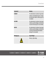
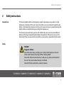
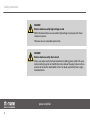
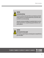
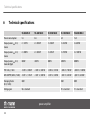
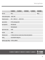
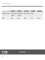
TA 450 MK-X
TA 600 MK-X
TA 1050 MK-X
TA 1400 MK-X
TA 2400 MK-X
power amplifier
user manual
Musikhaus Thomann e. K.
Treppendorf 30
96138 Burgebrach
Germany
Telephone: +49 (0) 9546 9223-0
E-mail: [email protected]
Internet: www.thomann.de
14.08.2012
Table of contents
Table of contents
1
General notes............................................................................................................................................... 4
2
Safety instructions..................................................................................................................................... 7
3
Features....................................................................................................................................................... 12
4
Installation and starting up................................................................................................................ 13
4.1 Pin assignment.................................................................................................................................. 13
5
Connections and operating elements........................................................................................... 17
6
Technical specifications....................................................................................................................... 22
7
Protecting the environment.............................................................................................................. 25
TA 450 MK-X TA 600 MK-X TA 1050 MK-X TA 1400 MK-X TA 2400 MK-X
3
General notes
1
General notes
This user manual contains important information on safe operation of the device. Read and
follow all safety notes and all instructions. Save this manual for future reference. Make sure
that it is available to all persons using this device. If you sell the device, include the manual for
the next owner.
Our products are subject to a process of continuous development. We therefore reserve the
right to make changes without notice.
Symbols and signal words
This section provides an overview of the symbols and signal words used in this user manual.
power amplifier
4
General notes
Signal word
Meaning
DANGER!
This combination of symbol and signal word
indicates an immediate dangerous situation
that will result in death or serious injury if it is
not avoided.
CAUTION!
This combination of symbol and signal word
indicates a possible dangerous situation that
can result in minor injury if it is not avoided.
NOTICE!
This combination of symbol and signal word
indicates a possible dangerous situation that
can result in material and environmental
damage if it is not avoided.
Warning signs
Type of danger
Warning – high-voltage.
TA 450 MK-X TA 600 MK-X TA 1050 MK-X TA 1400 MK-X TA 2400 MK-X
5
General notes
Warning signs
Type of danger
Warning – danger zone.
power amplifier
6
Safety instructions
2
Safety instructions
Intended use
This device amplifies electric audio frequency signals to operate passive speakers. Use the
device only as described in this user manual. Any other use or use under other operating con‐
ditions is considered to be improper and may result in personal injury or property damage. No
liability will be assumed for damages resulting from improper use.
This device may be used only by persons with sufficient physical, sensorial, and intellectual
abilities and having corresponding knowledge and experience. Other persons may use this
device only if they are supervised or instructed by a person who is responsible for their safety.
Safety
DANGER!
Danger for children
Ensure that plastic bags, packaging, etc. are disposed of properly and are not
within reach of babies and young children. Choking hazard!
Ensure that children do not detach any small parts (e.g. knobs or the like) from
the unit. They could swallow the pieces and choke!
Never let children unattended use electrical devices.
TA 450 MK-X TA 600 MK-X TA 1050 MK-X TA 1400 MK-X TA 2400 MK-X
7
Safety instructions
DANGER!
Electric shock caused by high voltages inside
Within the device there are areas where high voltages may be present. Never
remove any covers.
There are no user-serviceable parts inside.
DANGER!
Electric shock caused by short-circuit
Always use proper ready-made insulated mains cabling (power cord) with a pro‐
tective contact plug. Do not modify the mains cable or the plug. Failure to do so
could result in electric shock/death or fire. If in doubt, seek advice from a regis‐
tered electrician.
power amplifier
8
Safety instructions
CAUTION!
Possible hearing damage
The device can produce volume levels that may cause temporary or permanent
hearing impairment. Over an extended period of time, even levels that seem to
be uncritical can cause hearing damage.
Decrease the volume level immediately if you experience ringing in your ears or
hearing impairment. If this is not possible, keep a greater distance or use suffi‐
cient ear protectors.
CAUTION!
Risk of injury due to heavy weight
Due to the heavy weight of the device, at least two persons are required for trans‐
port and installation.
TA 450 MK-X TA 600 MK-X TA 1050 MK-X TA 1400 MK-X TA 2400 MK-X
9
Safety instructions
NOTICE!
Risk of fire
Do not block areas of ventilation. Do not install the device near any direct heat
source. Keep the device away from naked flames.
NOTICE!
Operating conditions
This device has been designed for indoor use only. To prevent damage, never
expose the device to any liquid or moisture. Avoid direct sunlight, heavy dirt, and
strong vibrations.
power amplifier
10
Safety instructions
NOTICE!
Power supply
Before connecting the device, ensure that the input voltage (AC outlet) matches
the voltage rating of the device and that the AC outlet is protected by a residual
current circuit breaker. Failure to do so could result in damage to the device and
possibly injure the user.
Unplug the device before electrical storms occur and when it is unused for long
periods of time to reduce the risk of electric shock or fire.
NOTICE!
Magnetic fields
The device generates strong magnetic fields that can interfere with the function
of poorly shielded devices. The strongest magnetic fields are directly above and
below the power amplifier. Therefore, never place sensitive devices such as preamplifiers, radio transmission systems, or tape decks directly above or below the
power amplifier. When installing the power amplifier into a rack, you should place
it in the lowest position, and further equipment such as pre-amplifiers in the
highest position.
TA 450 MK-X TA 600 MK-X TA 1050 MK-X TA 1400 MK-X TA 2400 MK-X
11
Features
3
Features
n Inputs
– 2 × XLR
– 2 × 1/4" phone sockets
n Outputs
– 2 × NL4 (lockable)
– 2 × screw terminals
n Protection circuits
– Audio limiter
– Thermal protection
– Short circuit protection
– DC protection
– Overcurrent
– Subsonic noise protection
n Cooling via integrated two-stage fans
n Suitable for 19" racks (2 RU, installation depth 44 cm)
power amplifier
12
Installation and starting up
4
Installation and starting up
Unpack and check carefully there is no transportation damage before using the unit. Keep the
equipment packaging. To fully protect the device against vibration, dust and moisture during
transportation or storage use the original packaging or your own packaging material suitable
for transport or storage, respectively.
Establish all connections as long as the unit is switched off. Use the shortest possible highquality cables for all connections.
4.1 Pin assignment
You can use XLR and 1/4" plugs with balanced or unbalanced wiring. In the following, we will
give you an overview of the various options
TA 450 MK-X TA 600 MK-X TA 1050 MK-X TA 1400 MK-X TA 2400 MK-X
13
Installation and starting up
XLR connections for signal
inputs
Balanced XLR mounting sockets serve as signal inputs. The following drawings and tables indi‐
cate the XLR pin assignment.
Balanced wiring:
1
Ground, shielding
2
Positive signal (+)
3
Negative signal (–)
Unbalanced wiring:
1
Ground, shielding
2
Signal
3
Bridged to pin 1
power amplifier
14
Installation and starting up
1/4" phone sockets for signal
inputs
The TRS inputs of the amplifier are only suitable for mono operation. The following drawings
and tables indicate the pin assignment of a 1/4" phone plug to be used.
Balanced wiring:
1 (Tip)
Positive signal (+)
2 (Ring)
Negative signal (–)
3 (Sleeve)
Ground, shielding
Unbalanced wiring:
1
Signal
2, 3
Ground, shielding
TA 450 MK-X TA 600 MK-X TA 1050 MK-X TA 1400 MK-X TA 2400 MK-X
15
Installation and starting up
NL4 mounting connectors
The drawing alongside shows the pin assignment of the lockable NL4 mounting connectors.
power amplifier
16
Connections and operating elements
5
Connections and operating elements
Front panel
TA 450 MK-X TA 600 MK-X TA 1050 MK-X TA 1400 MK-X TA 2400 MK-X
17
Connections and operating elements
1 POWER
Main switch to turn the device on or off.
2 CH-A/B
Input gain control for the channels CH-A and CH-B.
3 LED indicators for channels CH-A/B
These LEDs indicate operational readiness of the unit (Power), the input signal level (Signal), overloading (Clip) and
fault condition (Fault) an.
During operation, the Power LED lights up constantly. The Signal LEDs respond to
the input signal. If one of these LEDs lights up without an input signal is present, dis‐
connect the speakers from the amp and turn the input gain control of both channels
down to minimum. If the LEDs continue to light up, the device must be inspected by
an authorized service centre.
power amplifier
18
Connections and operating elements
Rear panel
TA 450 MK-X TA 600 MK-X TA 1050 MK-X TA 1400 MK-X TA 2400 MK-X
19
Connections and operating elements
4 Fuse holder.
5 OUT A | OUT B
Lockable NL4 mounting connectors for signal outputs to connect speakers.
6 OUT A | OUT B
Screw terminals (+/–) for signal outputs to connect speakers.
7 IN A | IN B
XLR mounting connectors for signal inputs.
8 IN A | IN B
1/4" phone sockets for signal inputs.
9 STEREO | PARALLEL | BRIDGED switch
Switch to select the operating modes ‘STEREO’ (both channels operate independently of each other), ‘PARALLEL’ (the
inputs of both channel are interconnected) and ‘BRIDGED’ (both channels are interconnected to form one channel
with double output power).
power amplifier
20
Connections and operating elements
10 Lift | Ground switch
Use the Ground / Lift switch to separate the connection between the earth pin of the device and the signal ground in
the unit. This prevents ground loops (position ‘Lift’ [switch is not pressed]: no connection. Position ‘Ground’ [switch is
pressed]: earth pin and signal ground are electrically connected).
11 IEC chassis connector for operating voltage supply.
TA 450 MK-X TA 600 MK-X TA 1050 MK-X TA 1400 MK-X TA 2400 MK-X
21
Technical specifications
6
Technical specifications
TA 450 MK-X
TA 600 MK-X
TA 1050 MK-X
TA 1400 MK-X
TA 2400 MK-X
Power consumption
5A
6A
7A
8A
15 A
Output power RMS 8 W,
stereo
2 × 125 W
2 × 200 W
2 × 350 W
2 × 450 W
2 × 650 W
Output power RMS 4 W,
stereo
2 × 200 W
2 × 300 W
2 × 525 W
2 × 700 W
2 × 1200 W
Output power RMS 8 W,
mono bridged
300 W
450 W
800 W
1200 W
2000 W
THD 4 W @ 1 kHz
< 0.05 % / 200 W
< 0.05 % / 300 W
< 0.05 % / 525 W
< 0.05 % / 700 W
< 0.05 % / 1200 W
IMD-SMPTE (60 Hz, 7 kHz) < 0.01 % / 125 W
< 0.01 % / 200 W
< 0.01 % / 350 W
< 0.01 % / 450 W
< 0,01 % / 650 W
Damping factor
(8 W, 1 kHz)
300:1
350:1
500:1
Voltage gain
50 × standard
70 × standard
91 × standard
power amplifier
22
Technical specifications
TA 450 MK-X
TA 600 MK-X
Slew rate
40 V/ms
Common mode rejection
> 60 dB (1 kHz)
Frequency response
20 Hz … 20 kHz (+ 0.1 …– 3 dB, 1 W, 8 W)
Input sensitivity
0.775 V @ rated power (8 W)
Input impedance
20 kW (balanced)
TA 1050 MK-X
TA 1400 MK-X
TA 2400 MK-X
60 V/ms
10 kW (unbalanced)
Signal-to-noise ratio
103 dB
Crosstalk
< 60 dB
Protective circuits
DC, thermal, short circuit, subsonic noise and overcurrent protection
Cooling
two controlled DC voltage fans
Operating supply voltage AC 230 V
, 50/60 Hz
TA 450 MK-X TA 600 MK-X TA 1050 MK-X TA 1400 MK-X TA 2400 MK-X
23
Technical specifications
TA 450 MK-X
TA 600 MK-X
TA 1050 MK-X
TA 1400 MK-X
Dimensions (W × H × D)
483 mm × 103 mm 485 mm × 103 mm 483 mm × 103 mm × 475 mm
× 475 mm
× 470 mm
Weight
13.3 kg
13.7 kg
16.4 kg
power amplifier
24
17.5 kg
TA 2400 MK-X
19.7 kg
Protecting the environment
7
Protecting the environment
Disposal of the packaging mate‐
rial
For the transport and protective packaging, environmentally friendly materials have been
chosen that can be supplied to normal recycling.
Ensure that plastic bags, packaging, etc. are properly disposed of.
Do not just dispose of these materials with your normal household waste, but make sure that
they are collected for recycling. Please follow the notes and markings on the packaging.
Disposal of your old device
This device is subject to the European directive 2002/96/EC.
Do not dispose of the device with your normal household waste.
Dispose of this device through an approved waste disposal firm or through your local waste
facility. When discarding the device, comply with the rules and regulations that apply in your
country. If in doubt, consult your local waste disposal facility.
TA 450 MK-X TA 600 MK-X TA 1050 MK-X TA 1400 MK-X TA 2400 MK-X
25
Notes
power amplifier
26
Musikhaus Thomann e.K. · Treppendorf 30 · 96138 Burgebrach · Germany · www.thomann.de