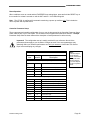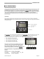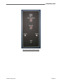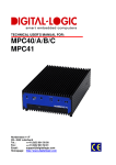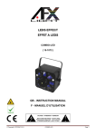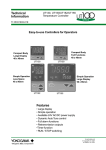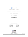
1
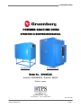
GRUENBERG OVEN POWDER COATING OVEN OPERATION & MAINTENANCE MANUAL Model MPC35.21 Model MPC45.96 - 2D Model No. MPCXX.XX Serial No. XXXXXXXXXX, Order No. XXXXX Part No. xxxxxx 2821 Old Route 15 New Columbia, PA 17856 570-538-7200 Fax: 570-538-7380 Rev. 04/17/09 Powder Coating Oven Page 1 GRUENBERG OVEN TABLE OF CONTENTS SECTION Page INFORMATION 1.0 COMPANY INFORMATION & ASSISTANCE ____________________________________ 4 2.0 SAFETY WARNINGS & SYMBOLS ___________________________________________ 5,6 3.0 PRODUCT OVERVIEW & SPECIFICATIONS 3.1 3.2 3.3 3.4 3.5 3.6 Application _______________________________________________________________ Specifications ____________________________________________________________ Conditioning Functions with an Electric Heating System ___________________________ Conditioning Functions with a Gas Fired Heating System __________________________ Control Equipment Features _________________________________________________ Operating Parameters and Requirements _______________________________________ 4.0 DRAWINGS, INFORMATION, and VENDOR INSTRUCTION LISTINGS ______________ 10 5.0 INSTALLATION INSTRUCTIONS 5.1 5.2 5.3 5.4 5.5 5.6 5.7 5.7.1 5.8 5.9 Delivery and Uncrating of Unit ________________________________________________ Location and Installation of Unit ______________________________________________ Equipment Access & Features _______________________________________________ Exhaust Connection for Electric Heated Units ___________________________________ Exhaust Connection for Gas Heated Units ______________________________________ Gas Supply Connection for Gas Heated Units ___________________________________ Power Supply Specifications _________________________________________________ Electric Heated Units – Ratings & Wiring Specifications ___________________________ Making the Power Supply Connection to the Chamber _____________________________ Application of Power _______________________________________________________ 7 8 8 8 9 9 11 11 12,13 14 14 15 16 17 18,19 19 SYSTEMS and CONTROL 6.0 AIR CIRCULATION SYSTEM – ELECTRIC HEATED UNITS 6.1 6.2 Overview ________________________________________________________________ 20 Airflow Description ________________________________________________________ 21-24 7.0 ELECTRIC HEAT CONTROL SYSTEM ________________________________________ 25 8.0 AIR CIRCULATION SYSTEM – GAS FIRED HEATED UNITS 8.1 Overview ________________________________________________________________ 26 Powder Coating Oven Page 2 GRUENBERG OVEN 8.2 8.3 8.4 Airflow Description – Double Module Using Blower Wheels _________________________ 27 Airflow Description – Double Module Using Fans _________________________________ 28,29 Special Equipment ________________________________________________________ 30,31 9.0 GAS HEATING SYSTEM ___________________________________________________ 32-35 10.0 TEMPERATURE CONTROL - YOKOGAWA UT150 CONTROLLER 10.1 10.2 10.3 10.5 Controller Features ________________________________________________________ Temperature Control _______________________________________________________ Setting the Alarm Setpoint - Used to Start the Heat Process Timing Cycle _____________ UT150 Controller Parameter Setup ____________________________________________ 11.0 OVERTEMPERATURE PROTECTION - YOKOGAWA UT150L _____________________ 39,40 12.0 PROCESS TIMER ________________________________________________________ 41 36 37 37 38 CHAMBER OPERATION & MAINTENANCE 13.0 SEQUENCE OF OPERATION for ELECTRIC HEATED UNITS ______________________ 42,43 14.0 SEQUENCE OF OPERATION for GAS FIRED UNITS _____________________________ 44,45 15.0 PREVENTATIVE MAINTENANCE & SERVICE __________________________________ 46 15.1 15.2 15.3 Cleaning ________________________________________________________________ 46 Maintenance Checks / Procedures ____________________________________________ 46,47 Preventative Maintenance Schedule / Log ______________________________________ 48 16.0 TROUBLESHOOTING – ELECTRIC HEATED SYSTEMS ONLY ____________________ 49,50 SUPPLEMENTAL INSTRUCTIONS Powder Coating Oven Page 3 GRUENBERG OVEN 1.0 COMPANY INFORMATION & ASSISTANCE Congratulations on purchasing a chamber from one of the fine divisions of TPS - Thermal Product Solutions. You probably already know us as Lunaire Limited. We’ve changed our name and expanded our vision with the intent to provide you with more diversified solutions to your thermal product process requirements. We truly hope that every aspect of chamber design and quality will measure up to your strictest standards. Your chamber has been designed to operate with the reliability you expect for the demands you impose on your product and research testing. Headquartered in New Columbia, Pennsylvania, which is located in the North-central part of the state, TPS includes the following five divisions that manufacture environmental test chambers and industrial ovens. Tenney Environmental - - - - Lunaire Environmental - - - - Gruenberg Oven - - - - Blue M - - - - Lindberg Parts and service inquiries for equipment within each division should be directed to TPS by any of the following methods. Important! Please have the Model and Serial Numbers of your unit available when contacting us. Model No. Serial No. Thermal Product Solutions PO Box 150 White Deer, PA 17887 Thermal Product Solutions 2821 Old Route 15 New Columbia, PA 17856 Phone: 570 - 538 - 7200 Fax - Parts Dept. 570 - 538 - 7385 Fax - Service Dept. 570 - 538 - 7391 Fax - Main: 570 - 538 - 7380 E - Mail Address: [email protected] Web site: www.thermalproductsolutions.com Mailing Address Physical Address Parts Replacement Your equipment has been designed and manufactured to provide years of reliable service. In the event a component should fail, it is recommended that only OEM approved parts be used as replacements. Please contact the Parts Department for component replacement, or repair. Powder Coating Oven Page 4 GRUENBERG OVEN 2.0 SAFETY WARNINGS & SYMBOLS You must follow these and all Warning statements listed throughout the manual! 1. Read this entire Operation Manual, as well as the vendor manuals and cut-sheets provided before operating this equipment! Failure to adhere to any Safety Warning, or failure to follow the proper operating procedures listed throughout any of the information provided, could cause damage to your equipment, personal injury, or death. 2. Obey all “CAUTION”, “DANGER”, and “WARNING” signs / labels mounted on the equipment. Do not remove any of these signs / labels. 3. Do not use this equipment in any manner not specified in this manual. Improper use may impair the safety features employed and will void your warranty. 4. This equipment is NOT designed for use with volatile or explosive materials unless specifically stated in your purchase order. Loading of such materials may result in explosion or fire. 5. Operators and service personnel must be familiar with the location and function of all controls and the inherent dangers of the equipment before operating or maintaining it. 6. Only qualified service personnel should ever be permitted to perform any service-related procedure on this equipment! 7. Do not place the unit near combustible materials or hazardous fumes or vapors. 8. Do not install unit in a corrosive environment. A corrosive environment may lead to poor performance and deterioration of unit. 9. Make sure the chamber and any remote equipment provided are leveled when installed. The chamber door may swing shut on personnel if unit is tilted. 10. A main power disconnect may not be provided with your unit. If not provided, we recommend that a fused disconnect switch on a separate branch circuit be installed as the power source in accordance with all National and Local Electrical Codes. 11. Do not position the chamber in a manner that would make it difficult to operate your main power disconnect switch. 12. Your power supply line voltage may be too low or too high to properly and safely operate your equipment. Before making the power supply connection to your equipment, you must follow the specific directions stated under “Power Connection” in the Installation Instructions section. Failing to perform the directions stated may damage your equipment and void your warranty! 13. Control panels, gauge boxes, the conditioning compartment, etc., contain exposed electrical connections. Keep panels in place properly when the unit is in operation. Disconnect and Lock-Out / Tag-Out all electrical power from the unit at its source before servicing or cleaning. 14. Do not adjust any mechanical components or any electrical components except as directed in this manual. 15. Do not overload the floor of the chamber workspace or load the unit unevenly. 16. Do not exceed the temperature rating of your chamber. Powder Coating Oven Page 5 GRUENBERG OVEN 17. Human exposure to temperature extremes can cause injury. Do not open oven doors until oven temperature drops below 200° F (93° C), when applicable. Take appropriate precautions before opening oven doors and upon handling any chamber contents. 18. Always cool the oven down below 167° F (75° C) before shutting it down. Otherwise, damage to the circulation motor shaft bearings will result. 19. Do not modify any component on this unit. Use only original equipment manufactured (OEM) parts as replacement parts. Modifications to any component, or the use of a non-OEM replacement part could cause damage to your equipment, personal injury, or death. 20. Do not stand on the roof of the oven. The roof is not designed to withstand additional weight. INTERNATIONAL WARNING / SAFETY SYMBOL DEFINITIONS Obey all “DANGER”, “WARNING”, and “CAUTION” labels shown in the manual and mounted on the equipment. Do not remove any labels mounted on the equipment. “WARNING OF HAZARDOUS AREA” “WARNING OF DANGEROUS ELECTRIC VOLTAGE” “WARNING OF HOT SURFACE” “EARTH (GROUND) PROTECTIVE CONDUCTOR TERMINAL” Powder Coating Oven Page 6 GRUENBERG OVEN 3.0 3.1 PRODUCT OVERVIEW & SPECIFICATIONS Application This manual applies to the Gruenberg Powder Coating MPC Series Ovens. These ovens are designed with ruggedness and operational simplicity to meet a variety of demands for the paint, powder, and coating heat processes. The oven interior consists of aluminized cold rolled steel with a ceiling that can support a hangar bar loaded with 250 pounds. This diverse series of ovens includes a bench top model for reach-in applications, and modular walk-in types that can be configured for expanded applications requiring increased processing quantities. Standard ovens employ an electric heating system. Gas heating systems that use either natural gas or liquid propane may also be employed. Their use would be designated in the model number with the letter “G”, e.g., Model 2MPCG45.96 - 2D. Standard model numbers with electric systems are listed and described below. Gas fired units are similar in size and temperature ratings, and are more detailed in Section 3.4. Model MPC35.21 Model MPC45.96 - 2D Model 2MPC45.96 - 2D Model 2MPC45.96 - 2D - C Model 3MPC45.96 - 2D - C The Model MPC35.21 is a reach-in type oven that has a workspace capacity of 21 cubic feet, and an operating temperature of 450° F maximum. This bench sized oven may be provided with a mounting stand. The Model MPC45.96 - 2D is a walk-in type oven that has a workspace capacity of 96 cubic feet, and an operating temperature of 450° F max. Split double doors provide easy access to the workspace. This unit is a modular design, having a removable back wall panel for the addition of another 96 cubic foot module. The Model 2MPC45.96 - 2D incorporates two 96 cubic foot modules assembled together. The second module has no conditioning equipment or controls. Only the shell is provided along with a plenum extension panel, which attaches to the main module plenum panel. The extension plenum panel directs the flow of conditioned air into the workspace of the second module. This oven is normally shipped as a one-piece unit. The Model 2MPC45.96 - 2D - C incorporates two 96 cubic foot modules assembled together with the second module employing an identical conditioning plenum to that of the main module. Fans and heaters of the second module operate in tandem with the main module and are controlled by the main control circuitry. The Model 3MPC45.96 - 2D - C incorporates three 96 cubic foot modules assembled together. The second module is a basic blank shell. The third module employs an identical conditioning plenum to that of the first module. Fan and heaters of this module operate in tandem with the first module. Note: An optional 250 lb. capacity part hanging bar assembly may be installed in each module. Powder Coating Oven Page 7 GRUENBERG OVEN 3.2 Specifications POWDER COATING OVEN SPECIFICATIONS 3.3 Temperature Rating (Maximum) Workspace Capacity MPC35.21 450° F 35 Cubic Feet MPC45.96 - 2D 450° F 96 Cubic Feet 2MPC45.96 - 2D 450° F 192 Cubic Feet 2MPC45.96 - 2D - C 450° F 192 Cubic Feet 3MPC45.96 - 2D - C 450° F 288 Cubic Feet Conditioning Functions with an Electric Heating System Heating of the oven with an electric heating system is achieved by recirculating oven air through Incoloy sheathed tubular heaters. The heaters are mounted in the conditioning plenum, and are isolated from the workspace to prevent direct heat radiation. Air circulation is generated by either one or two propeller type fans, which are driven by externally mounted motors. The Model MPC35.21 employs one fan, while the Model MPC45.96 employs two. Air flow is in a compound horizontal pattern through the oven workspace. A two inch diameter exhaust port is provided at the top of the oven to vent moisture or undesirable vapors given off by your heating process. An exhaust kit for connection to an exhaust stack is optional. 3.4 Conditioning Functions with a Gas Fired Heating System Gas fired ovens are heated using either natural gas or liquid propane. These ovens are direct-fired units. Process air is recirculated through a vertical burner manifold in the conditioning plenum. Air circulation is generated by either one or two propeller type fans or centrifugal type blower wheels, which are driven by externally mounted motors. The Model MPCG35.21 employs one blower wheel, while the modular Model MPCG45.96 units employ two. When an additional 96 cubic foot module is added, the entire unit can employ either blower wheels or fans for airflow generation. Units with blower wheels employ a horizontal front-to-back air flow pattern in the workspace. Units with fans employ a compound horizontal air flow pattern in the workspace. An exhaust blower is provided along with an air intake port to maintain a constant flow of fresh ambient air through the oven. A purge timer is used to purge oven air equal to four volumes of the oven interior before a new process cycle is allowed to begin. Note: Gas heated units are designed with some slightly different configurations than those with electric heating systems due to the dangers associated with explosive vapors. Powder Coating Oven Page 8 GRUENBERG OVEN 3.5 Control Equipment Features Temperature Controller: Temperature conditions are controlled by a Yokogawa Model UT150 Controller. The UT150 is a non-profiling type 1/16 DIN single channel controller that features automatic control. Either a time proportioned heat output or a 4-20 ma control signal is used for precise temperature control. Overtemperature Protection: A Yokogawa Model UT150L Limit Controller is provided for overtemperature protection. The UT150L will remove power to the heating system when an over temperature condition is detected. Alarm circuitry may be included as an option. Process Timer: An Eagle Signal Model B856 Process Timer is provided, which has five user-selectable timing ranges from 0.01 seconds to 9999 hours. The timer will automatically start timing once the process setpoint temperature is reached. When the total preset time has elapsed, power to the heat control circuitry will be disabled. Additional Features: Gruenberg ovens are designed with the capability to incorporate many other optional features for safety purposes, enhanced process control, and simplified operator interface. Consult a Gruenberg Applications Engineer or our Service Department for more information or questions. 3.6 Operating Parameters and Requirements This equipment is designed to operate safely when the following environmental conditions are met: Indoor use only. Within a temperature range of 5°C to 30°C (max). Maximum relative humidity 90%. The listed chamber specifications are based on operation at 24° C ambient temperature, altitude at sea level, and a 60 Hz power supply. Chamber operation utilizing a 50 Hz power supply may derate the listed performance specifications. Equipment damage, personal injury, or death may result if this equipment is operated or maintained by untrained personnel. Operators and service personnel must be familiar with the location and function of all controls and the inherent dangers of the equipment before operating or maintaining it. TPS shall not be liable for any damages, including incidental and/or consequential damages, regardless of the legal theory asserted, including negligence and/or strict liability. Observe all safety warnings and operating parameters listed in this manual, as well as all Caution, Danger, and Warning signs or labels mounted on the equipment to reduce the risk of equipment damage and personal injury. Powder Coating Oven Page 9 GRUENBERG OVEN 4.0 DRAWINGS, INFORMATION, and VENDOR INSTRUCTION LISTINGS The following drawings are provided: Electrical Schematic(s) A800, A8xx Relay Pan Layout A801 General Layout D001 Gas Burner Train Layout (Gas Fired Units) D5xx The following information and vendor manuals are provided: Electrical Parts List Yokogawa UT150 Temperature Controller Manual Yokogawa UT150L Limit Controller Manual Eagle Signal B856 Timer Manual Gas Burner Manual (Gas Fired Units) Note: Various other vendor manuals and product information sheets may be provided, which contain important operation and maintenance instructions. Their inclusion is subject to vendor availability. Powder Coating Oven Page 10 GRUENBERG OVEN 5.0 INSTALLATION INSTRUCTIONS Read this section completely before attempting to install, or operate the equipment. 5.1 Delivery and Uncrating of Unit Inspect equipment and shipping crate immediately upon receipt. If any damage is apparent, you should discuss it with the trucking delivery person and contact the transportation company immediately. Make notes of any damage on the Bill Of Lading. Retain all shipping materials for inspection. Any claims for damage must start at the receiving point. Check packing slip carefully and make sure all materials have been received as indicated on the packing ticket. Unless otherwise noted, YOUR ORDER HAS BEEN SHIPPED COMPLETE. Chambers and any remote machinery skids or control cabinets should be handled and transported in an upright position. They must never be carried on their back, front, or any side unless clearly indicated on the shipping pallet. Important! Do to the vibration incurred during shipping and handling, it is possible that mechanical connections could become loose. Check all connections to make sure they are secure. Four removable lifting lugs are normally provided on top of the oven to lift and move your unit with the proper handling equipment. Follow the installation requirements below. 5.2 Location and Installation of Unit Oven Classification – Electric Heated Units: NFPA 86 Class B ovens are heat utilization equipment operating at approximately atmospheric pressure wherein there are no flammable volatiles or combustible material being heated in the oven. Oven Classification – Gas Heated Units: NFPA 86 Class A: “Class A ovens and furnaces are heat utilization equipment operating at approximately atmospheric pressure wherein there is a potential explosion or fire hazard that could be occasioned by the presence of flammable volatiles or combustible materials processed or heated in the furnace.” Do not locate unit in areas of wide ambient temperature variation such as near vents or outdoor entrances. Do not place the unit near combustible materials or hazardous fumes or vapors. Do not install unit in a corrosive environment. A corrosive environment may lead to poor performance and deterioration of unit. Ventilation: The oven should be installed in an area where there is good air ventilation. Allow a minimum of 5 inches between any wall and any oven side. Do not position the oven in a manner that would make it difficult to operate your main power disconnect switch. Make sure the oven is leveled when set up. The floor of the chamber should be leveled with a Spirit Level to +/- 1/8” (3.175 mm) front to back and side to side. Sometimes control panels are removed to facilitate shipment. When required, replace the panels securely and reconnect numbered electrical wires to matching numbered terminal blocks. Very Important! Upon completion of the initial installation of the chamber and upon completion of any maintenance procedure, make sure that all access panels that have been removed are reinstalled securely before operating the unit. Powder Coating Oven Page 11 GRUENBERG OVEN 5.3 Equipment Access and Features Door Latches Exhaust Port Control Cabinet SINGLE MODULE - FRONT RIGHT VIEW Lifting Lugs Exhaust Port SINGLE MODULE (MPC) - FRONT TOP VIEW Powder Coating Oven Page 12 GRUENBERG OVEN DOUBLE MODULE (2MPC) - FRONT RIGHT VIEW Exhaust Blower & Port Gas Burner Train nd 2 Module Conditioner Motor Cabinet Control Cabinet GAS FIRED - DOUBLE MODULE (2MPCG) - FRONT RIGHT VIEW Powder Coating Oven Page 13 GRUENBERG OVEN 5.4 Exhaust Connection for Electric Heated Units A two inch exhaust port is provided at the top of the oven to purge moisture or undesirable vapors given off by your heating process. When exhausting undesirable / harmful vapors, an exhaust duct should be connected to the port and run to a location outside of the building, in accordance with all local code regulations. As an option, an exhaust kit may be provided for connection of the 2 inch port to an exhaust stack. Exhaust Port EXHAUST PORT 5.5 Exhaust Connection for Gas Heated Units An exhaust port connection consisting of a 6” O.D. collar is installed with the exhaust blower assembly at the top of the oven. The exhaust housing includes a manual damper. A vent duct should be connected to the exhaust port collar and run to a location outside of the building (as necessary). This should be done in accordance with all local code regulations. Make sure the connection is secure. Differential Pressure Switch Manual Damper EXHAUST BLOWER & PORT Powder Coating Oven Page 14 GRUENBERG OVEN 5.6 Gas Supply Connection for Gas Heated Units Gas fired ovens may use either natural gas or liquid propane for combustion to heat the oven. You must follow your specific supply specifications listed on your General Arrangement Drawing D001 and when listed here. Important! Please read the entire Gas Heating System section and all vendor manuals / cutsheets to familiarize yourself with all gas components before making your gas supply connection. The gas supply connection is made to a ball valve with a ½” FPT type connection. Make sure the connection is secure and is checked for leaks before operation. Gas Supply - Liquid Propane: Pressure = xxx PSIG, xxxx CFH Gas Supply - Natural Gas: Pressure = xxx PSIG, xxxx CFH Dual Gas Solenoid Valve High Gas Pressure Switch Valve Position Indicators Low Gas Pressure Switch Gas Inlet with Ball Shutoff Valve Red = Open White = Closed DUNGS DUAL GAS VALVE CHECK SYSTEM & SUPPLY CONNECTION IMPORTANT! YOU MUST REFER TO THE ENCLOSED VENDOR'S MANUALS FOR COMPLETE COMPONENT SAFETY AND OPERATING INSTRUCTIONS. DANGER! NEVER BYPASS ANY SAFETY FEATURE. DANGER! NEVER ATTEMPT TO LIGHT THE BURNER IF ANY COMPONENT WITHIN THE FACILITY SHOWS SIGNS OF DAMAGE OR MALFUNCTIONING. Powder Coating Oven Page 15 GRUENBERG OVEN 5.7 Power Supply Specifications Important! Power supply specifications are unique for electric heated units and for gas fired heated units. Make sure that you read and understand this entire section before proceeding. For standard electric heated units, reference the chart on the following page and your serial tag. For special oven Model No. xxxxxxxxxxxxxxxxxxx, O/N xxxxx, the following custom power supply specifications apply. xxx VAC, x PH, xx HZ, xxx A Your Main Power Disconnect should be rated xxx Amps. Warning! Before making the power supply connection to your unit, you must perform the following procedure: 1. Verify the power supply voltage rating established for your chamber (if listed above). The voltage rating is also found on the serial tag on the side of the oven. Note the rated value here: For electric heated units, also refer to the expanded Electrical Specifications Chart in Section 5.7.1. 2. Measure and record the intended voltage source. Note the measured value here: 3. Reference the “Line Voltage Min/Max Tables” below. Verify that the power supply voltage source you measured and recorded is within the minimum and maximum allowable operating voltages for your chamber voltage rating. If it is not within this operating range, do not make the power connection! Otherwise, erratic operation and damage may occur to your equipment, which may void your warranty. If you have any questions, please call the TPS Service Department. Important! One of the most common causes of equipment malfunction is low line voltage as the power source to the unit. Ordinarily in this condition, the heat output would be reduced and the system's motors would operate erratically, eventually overheat, and shut down. You must be certain that your equipment is connected to a circuit with an adequate voltage and current source. An oversupply voltage would also cause erratic operation and eventual shutdown, or damage to your equipment. - 60 HERTZ SUPPLIES - - 50 HERTZ SUPPLIES - LINE VOLTAGE MIN. / MAX. TABLE LINE VOLTAGE MIN. / MAX. TABLE Chamber Voltage Rating Minimum Voltage Maximum Voltage Chamber Voltage Rating Minimum Voltage Maximum Voltage 120 108 127 200 180 220 208 188 228 220 198 242 230 207 253 380 342 418 460 414 506 400 360 440 480 432 528 415 374 456 60 Hz Supply Operation outside these limits can result in damage to chamber equipment. Powder Coating Oven 50 Hz Supply Operation outside these limits can result in damage to chamber equipment. Page 16 GRUENBERG OVEN 5.7.1 Electric Heated Units – Ratings & Wiring Specifications The chart below is provided explicitly for electric heated units with a “Y” type power supply system due to the requirement of needing both a neutral and a ground connection. The total number of wires necessary in the power supply cable is listed. Consult your General Arrangement Drawing D001 and your serial tag if you are not employing a “Y” type power supply system for the Part Numbers listed below. Warning! When referring to the chart below, make sure you have the correct Model and Part No. Warning! All power supplies require both a neutral and a ground wire connection. ELECTRICAL SPECIFICATIONS CHART - 60 HERTZ UNITS Model Part No. Electrical Rating MPC35.21 800156 230 Volts, 26.6 Amps, 3 Phase, 5 Wire MPC35.21 800157 230 Volts, 42.7 Amps, 1 Phase, 4 Wire MPC45.96 - 2D 800129 230 Volts, 51.0 Amps, 3 Phase, 5 Wire MPC45.96 - 2D 800130 230 Volts, 76.0 Amps, 1 Phase, 4 Wire MPC45.96 - 2D 800131 460 Volts, 21.6 Amps, 3 Phase, 5 Wire 2MPC45.96 - 2D 800132 230 Volts, 51.0 Amps, 3 Phase, 5 Wire 2MPC45.96 - 2D 800133 230 Volts, 76.0 Amps, 1 Phase, 4 Wire 2MPC45.96 - 2D 800134 460 Volts, 21.6 Amps, 3 Phase, 5 Wire 2MPC45.96 - 2D - C Powder Coating Oven 800130 Expansion Page 17 GRUENBERG OVEN 5.8 Making the Power Supply Connection to the Chamber A main power disconnect switch is not provided with your chamber. We recommend that a fused disconnect switch on a separate branch circuit be installed as the power source to your chamber, in accordance with all national and local electrical codes. Reference your Electrical Schematic for all electrical requirements. The power supply connection is made to the main terminal blocks in the control cabinet, which are labeled for the correct service. A power supply cable entry hole may need to be punched into the main control cabinet. Warning! High Accessible Current – An Earth / Ground connection is essential before connecting the power supply. Make sure equipment is properly grounded in accordance with all codes. Utilize proper grounding techniques to also reduce RFI and EMI emissions. Electric heated units employing a “Y” type power supply also require a neutral connection. (See table in Section 5.7.1.) Warning! Make sure that all electrical wiring is properly installed in accordance with all National and Local Electric Codes. Make sure all connections are secure. Circ. Motor Main Terminal Blocks Electric Heater Conn.’s MAIN SUPPLY TERMINAL BLOCK – ELECTRIC HEATED UNIT Circ. Motor ELECTRIC HEATED CONTROL CABINET - MODEL MPC45.96 Powder Coating Oven Page 18 GRUENBERG OVEN Conditioner Motor Power Connection Conditioner Motors Purge Timer Conditioner Motor GAS HEATED CONTROL CABINETS (DUAL MODULE) – O/N 60530 5.9 Application of Power Before energizing any equipment, make a visual inspection for loose components, electrical connections, fittings, etc. Shut all operating switches to the “OFF” position before energizing. Have trained personnel start and check out the equipment before its first cycle. Powder Coating Oven Page 19 GRUENBERG OVEN 6.0 6.1 AIR CIRCULATION SYSTEM – ELECTRIC HEATED UNITS Overview A high volume compound horizontal airflow system is employed with the electric heating system to provide maximum temperature uniformity. The heating and generation of airflow occurs in the conditioning plenum, which is normally located on the right side wall of the oven. Air flow is generated by propeller type fans at approximately 2400 CFM. The fans are driven with extended shafts by motors mounted in the control cabinet. Heating is achieved with Incoloy sheathed type tubular heaters, which are suspended in the conditioning plenum. This location prevents direct radiation to the product. To condition the workspace, Model MPC35.21 ovens utilize one heater bank with one circulation fan, and the Model MPC45.96 - 2D ovens utilize two heater banks with two circulation fans. When additional heated modules are added to the MPC45.96 series, the plenums will be identical in construction and controlled by the same conditioning circuitry. Heaters CONDITIONING PLENUM - MODEL MPC45.96 - 2D Thermocouples used for temperature sensing are normally mounted on the plenum panel beneath the top fan opening. This location may vary with the double module Model 2MPC45.96 - 2D. Powder Coating Oven Page 20 GRUENBERG OVEN 6.2 Airflow Description Process air is drawn from the workspace by the fans into the plenum and is heated as it flows through the heaters. Heated air is discharged into the workspace through grates along both sides of the plenum panel. As the air exits the grates, it encounters the oven wall and is forced to flow into the workspace in a horizontal pattern throughout the entire height of the oven. Hot air conditions the product and returns to the plenum to continue the cycle. A small portion of process air is continually exhausted out through the 2 inch diameter exhaust port. Thermocouples MODEL MPC45.96 - 2D Powder Coating Oven Page 21 GRUENBERG OVEN Plenum Extension Panel Thermocouples DOUBLE MODULE - MODEL 2MPC45.96 - 2D Powder Coating Oven Page 22 GRUENBERG OVEN Plenum #2 Blank Extension Panel Plenum #1 Thermocouples Thermocouples TRIPLE MODULE - MODEL 3MPC45.96 - 2D - C Powder Coating Oven Page 23 GRUENBERG OVEN DOUBLE MODULE - HEATED - MODEL 2MPC45.96 - 2D - C Part Hanging Bar MODEL MPC35.21 (BENCH TYPE) Powder Coating Oven Page 24 GRUENBERG OVEN 7.0 ELECTRIC HEAT CONTROL SYSTEM Incoloy sheathed tubular heating elements are used to heat the oven. The unheated heater ends protrude through the wall of the oven and into the control cabinet where they are electrically terminated. Heat Control: The heat control circuitry is enabled through the High Limit output of the Yokogawa UT150L Limit Controller, along with either one or two heat enable contactors (CON1 / CON2). In the Model MPC35.21, one contactor is used in both single and three phase power supplied units. In the Model MPC45.96 - 2D, one contactor is used with a three phase power supply, and two contactors are used with a single phase power supply. Two contactors are required with a single phase supply because the heaters are split into two separate circuits. The heaters are controlled by the time proportioned Heat Output of the Yokogawa UT150 Temperature Controller. This output energizes a two-pole solid state relay, which provides power to the heaters. The relay employs two SCRs in each pole in a back-to-back configuration. Zero cross voltage switching is employed to give precise temperature control with minimal noise generation. SSR1 FAN AND HEATER BANK Powder Coating Oven Page 25 GRUENBERG OVEN 8.0 8.1 AIR CIRCULATION SYSTEM – GAS FIRED HEATED UNITS Overview Gas fired heating systems are normally installed in walk-in modular ovens. A high volume airflow system is employed to provide maximum temperature uniformity. The type of air circulation system used depends on the configuration of the unit. Single module units can only employ a horizontal front-to-back airflow type pattern using centrifugal type blower wheels to generate air circulation. Double module units can employ two different types of air circulation systems, as listed below. • • Horizontal front-to-back pattern using centrifugal type blower wheels. Compound horizontal pattern using propeller type fans. The heating and generation of airflow occurs in the conditioning plenum, which is normally located on the right side wall of the oven. Blower wheels or fans are driven with extended shafts by motors mounted in the control cabinet. Heating is achieved by a gas burner that directs a flame down into a vertical perforated flame tube mounted in the manifold next to the conditioning plenum. Thermocouples used for temperature sensing are normally mounted in the workspace on the plenum panel. Burner Manifold Blower Wheel Location Airflow Thermocouples Blower Wheel Location SINGLE MODULE - MODEL MPC45.96 - 2D Powder Coating Oven Page 26 GRUENBERG OVEN 8.2 Airflow Description – Double Module Using Blower Wheels Gas ovens using centrifugal type blower wheels for airflow generation employ a horizontal front-to-back type airflow system. The burner manifold is designed with a vertically mounted flame tube along with perforations on the back side of the manifold. Processed air is drawn into the burner manifold and conditioning plenum, and is heated as it mixes with hot air emitted from the flame tube. Fresh ambient air is also drawn into the plenum where it mixes with the heated air. Conditioned air is discharged into the workspace through perforations near the front of the plenum housing. The air flows back through the workspace in a horizontal manner to condition the product and then returns to the plenum for reconditioning. A portion of the processed air is exhausted through a port in the chamber ceiling by the exhaust blower. An air intake port with a manual slide damper is installed in the ceiling of each module to allow fresh ambient air to replenish the exhausted air. Slide dampers are mechanically locked to a predetermined minimum opening. Blower Wheel Location Thermocouples Airflow Blower Wheel Location DOUBLE MODULE with BLOWER WHEELS Powder Coating Oven Page 27 GRUENBERG OVEN 8.3 Airflow Description – Double Module Using Fans Gas ovens using propeller type fans for airflow generation employ a compound horizontal type airflow system. The burner manifold is designed with a vertically mounted flame tube along with air grates installed on the vertical sides. This design permits hot air emitted from the flame tube to be drawn into each module conditioning plenum. A close-up photo of the conditioning plenums is shown on the next page. Conditioner fans draw processed air from the workspace, hot air from the burner manifold, and fresh ambient intake air into the plenum. The air is mixed and then discharged into the workspace through a vertical grate installed on the ends of the plenum housing (opposite the burner manifold). Conditioned air flows in a horizontal pattern through the workspace and then back into the center of each plenum to be reconditioned. A portion of the processed air is exhausted through a port in the chamber ceiling by the exhaust blower. An air intake port with a manual slide damper is installed in the ceiling of each module to allow fresh ambient air to replenish the exhausted air. Slide dampers are mechanically locked to a predetermined minimum opening. Intake Air Ports Exhaust Port Thermocouple DOUBLE MODULE with FANS Powder Coating Oven Page 28 GRUENBERG OVEN Intake Airflow Diff. Press. Air Sense Tube Cover Discharge Air Burner Manifold Discharge Air DOUBLE MODULE with FANS Powder Coating Oven Page 29 GRUENBERG OVEN 8.4 Special Equipment Circulation Blower Spark-Proof Design: Gas ovens utilizing centrifugal type blower wheels for airflow generation employ non-sparking type construction. The blower housings and inlet rings are made of aluminum while the blower wheels are made of stainless steel. Should a blower wheel come off its shaft and strike the blower housing or inlet ring, no sparks can be generated between the two metals. Circulation Fan Spark-Proof Design: Gas ovens utilizing propeller type fans for airflow generation employ non-sparking type construction. The plenum housing and fan blade supports are made of stainless steel while the fan blades are made of aluminum. Should a fan blade become loose and strike the plenum housing, no sparks can be generated between the two dissimilar metals. Differential Air Pressure Switches (FLS): Differential air pressure type switches are used to monitor airflow generation of each fan or blower wheel, and for correct operation of each conditioner motor. Correct rotation of the motor is necessary for the switch to properly operate. These devices use a diaphragm to sense pressure and to mechanically trigger a SPDT Snap Switch when the proper pressure is developed across the blower wheel or fan. If a loss of pressure / airflow were detected, the switch would open and remove power from the gas burner. Loss of airflow may result from a motor malfunction or a loose blower wheel or fan. DIFF. PRESS. AIRFLOW SWITCH Powder Coating Oven Page 30 GRUENBERG OVEN Spark-proof Explosion Venting Latches: A Brixon Explosion Venting Latch is employed at the top of each chamber door to provide venting in the event of an internal explosion. The latches are non-sparking types, which are made of brass and are designed to release at a predetermined pressure. When chamber air pressure rises to the release point of the latch, the latch disengages and allows the door to blow out away from the chamber. Door Limit Switch DOOR LATCHES & DOOR SWITCH Door Limit Switch: A Door Limit Switch (LS1) is installed for the operation of two important functions. Initially it is used to sense that the chamber doors have been properly closed in order to start the air purge cycle and subsequently energize the gas burner. If during the process cycle the oven doors are inadvertently opened, LS1 will immediately cause the gas burner to shut down. The circulation and exhaust blowers will remain running. Powder Coating Oven Page 31 GRUENBERG OVEN 9.0 GAS HEATING SYSTEM Important Note: Due to the diverse array of configurations available in a gas heating system, this section will describe basic system requirements, standard equipment used, and fundamental operation. Application: Gruenberg gas heated ovens are designed to operate with either a natural gas supply or a liquid propane supply according to NFPA 86 (National Fire Protection Association) safety standards. To meet NFPA main gas train requirements, a Closed Position Indicator CPI is used for electrical indication of the safety valve closed position. A direct-fired type gas system is used in which the flame is shot through a burner manifold in the conditioning plenum. Recirculating oven air is heated as it is drawn through the flame. Direct-fired systems are typically greater than 90% efficient. Since products of combustion enter the workspace with this type, it is reserved for those processes that are not emission sensitive. However, many safety precautions are employed with a direct-fired system to compensate for the presence of an open flame. The following sections detail the standard gas heating components used and their operation. The actual components used will vary with your application, so it's important to check your oven specifications. IMPORTANT! YOU MUST REFER TO THE ENCLOSED VENDOR'S MANUALS FOR COMPLETE COMPONENT SAFETY AND OPERATING INSTRUCTIONS. DANGER! NEVER BYPASS ANY SAFETY FEATURE. DANGER! NEVER ATTEMPT TO LIGHT THE BURNER IF ANY COMPONENT WITHIN THE FACILITY SHOWS SIGNS OF DAMAGE OR MALFUNCTIONING. Exhaust Blower Shutoff Valve Modulation Valve Dual Gas Valve Inlet Supply Shutoff Valve Gas Burner Closed Position Indicators GAS BURNER TRAIN Powder Coating Oven Page 32 GRUENBERG OVEN Exhaust Blower: An exhaust blower is standard with all direct-fired systems to serve two purposes. Initially, the blower is used along with a purge air timer to purge oven air for a fixed time before the gas burner is fired. When the purge cycle time is complete, the exhaust blower is used to maintain a constant exchange of oven air with fresh ambient air. Ambient air is drawn into the oven through slide dampers mounted atop each module. A differential pressure switch is used to monitor airflow generation by the exhaust blower, and subsequently for correct operation of the blower motor. These devices use a diaphragm to sense pressure and to mechanically trigger a SPDT Snap Switch when the proper pressure is developed across the blower wheel (or fan). Correct rotation of the motor is necessary for the switch to operate properly. If a loss of pressure / airflow were detected, the switch would open and remove power from the gas burner. Loss of airflow may result from a motor malfunction, a loose blower wheel (or fan), or constricted air intake or exhaust ports. Blower Spark-Proof Design: The blower housing is designed with a non-sparking type construction. The housing and inlet rings are made of aluminum while the blower wheel is made of stainless steel. Should the blower wheel come off its shaft and strike the blower housing or inlet ring, no sparks can be generated between the two metals. Purge Oven Timer -- Direct-fired Units: A timed pre-ignition purge of the oven is required before each system start-up. A minimum of four complete air volume changes is necessary for the removal of all flammable vapors and gases that might have entered the workspace during the shutdown period. Residual gases in the plenum are also of concern. The Purge ON light on the main control panel will illuminate during the purge cycle. For O/N xxxxx, the exhaust purge time is x minutes at xxx CFM exhaust airflow. Air Intake Port Air Intake Port GAS BURNER TRAIN Powder Coating Oven Page 33 GRUENBERG OVEN Dungs Dual Gas Valve Check System: A Dungs Dual Gas Valve Check System is installed in the gas supply train. Low and high pressure monitoring chambers with pressure switches and safety shut-off valves are provided. The following safety features are employed. Low-Gas Pressure Switch: The gas supply first enters the dual gas valve system through a chamber that monitors for low gas pressure. When a predetermined inlet gas pressure rises above the minimum switch setting, the switch will close and the valve will energize and open to permit gas flow to the high pressure chamber. If the pressure drops below the switch setting, the switch will open and remove power to the burner. High-Gas Pressure Switch: After passing the through the low pressure chamber, the gas enters another chamber that is used to monitor for high pressure. The high-gas pressure switch is normally closed as long as the gas pressure is below a predetermined switch setting. The valve in this LOW-GAS PRESSURE SWITCH chamber is energized and opened to permit gas passage through to the rest of the gas train. If the pressure rises above the switch setting, the switch will open. The valve will deenergize and close to shut off the supply of gas to the rest of the gas train. The switch will also remove power to the burner. Valve (Visual) Position Indicator: Valve (Visual) Position Indicators are provided on the bottom of the dual valve system to give visual indication of whether each safety shut-off valve is opened or closed. A red indicator can be seen when the valve is open. A white indicator can be seen when the valve is closed. Eclipse Rotary Actuator – Heat Control: Heat control of the oven is achieved by regulating the flow of gas to the burner with a modulating valve in the gas train. An Eclipse Rotary Actuator is installed in the gas train after the dual valve check system. A modulation motor is installed in the actuator, which opens and closes a butterfly valve in the gas train to regulate gas flow to the burner. The motor is activated by a 4-20 ma process signal from the main temperature controller. ECLIPSE GAS MODULATION VALVE Powder Coating Oven Page 34 GRUENBERG OVEN Gas Burner - Combustion Blower: The three elements necessary for combustion are fuel, oxygen, and ignition. The combustion blower supplies a constant flow of fresh air to the burner. The air is mixed with gas by various methods in order to establish ignition and to sustain complete combustion. The combustion motor starts immediately when the OVEN ON switch is closed. A combustion airflow switch monitors airflow from the combustion blower. This is a differential air pressure type, which will shut down the burner if a loss of airflow is detected. Gas Burner: A burner is defined as a device used for the introduction of fuel and air into an oven at the required velocities, turbulence, and concentration to maintain ignition and combustion of fuel. A Blast type burner is normally used. This burner delivers a combustible mixture under pressure, normally above 0.3 inch W.C. to the combustion zone. Various flame safety devices are installed within the burner. Powder Coating Oven Page 35 GRUENBERG OVEN 10.0 10.1 TEMPERATURE CONTROLLER Controller Features Temperature control is achieved with the Yokogawa Model UT150 Controller. The UT150 is a non-profiling type, 1/16 DIN controller with the following main features. Single Channel Automatic Control Only 1 Input: Type J Thermocouple is used to sense oven temperature 1 Heat Control Output: Time Proportioned Alarm Output A1 - Used to Start Process Timing Alarm Output A2 - Not Used YOKOGAWA UT150 Displays: PV Display (Top): SP Display (Bot.): Process Value. Parameter and Error codes when appropriate. Setpoint Value. Parameter values when appropriate. Indicator Lights: OUT: AL 1 & 2: Output Light. Left OUT light illuminates whenever heat output energizes. Alarm Output 1 & 2. Illuminate when energized. Keys: Up Arrow: Down Arrow: Note: Changes parameter value. Increases setpoint value. Changes parameter value. Decreases setpoint value. Whenever you change the value of a setpoint or parameter, the decimal point flashes to remind you to register the change by pressing the SET/ENT Key. SET/ENT Key: Data Registering Key - performs the following functions: - Registers the data value changed using the data change (up / down arrow) keys. Switches between operating displays or parameter setting displays sequentially. Pressing the key for 3 seconds or longer in the normal operation display retrieves the Operating Parameter Setting display. Pressing the key for 3 seconds or longer in either the Operating or Setup Parameter Setting display, transfers back to the normal operation display. Powder Coating Oven Page 36 GRUENBERG OVEN 10.2 Temperature Control Electric Heated Units: Temperature control with the Yokogawa UT150 is achieved with a time proportioned output signal (Output 1). This output will energize solid state relay SSR1, which closes to provide power to the electric heaters. Gas Fired Heated Units: Temperature control with the Yokogawa UT150 Controller is achieved with a 4-20 ma output signal. This signal is sent to the modulation motor, which regulates the flow of gas to the burner with a butterfly valve. Setting the Temperature Setpoint: To enter a temperature setpoint, follow the procedure below. 1. 2. 10.3 Press the Up / Down Arrow keys until the desired setpoint is indicated on the bottom display. (The period will flash while changing.) Press the SET/ENT key to register the new setpoint. Setting the Alarm Setpoint - Used to Start the Heat Process Timing Cycle Alarm Setpoint A1 is the temperature setpoint that is used to start the heat process timing cycle. A1 is preset to a value that is between 2 and 5 degrees below the heat process Setpoint Temperature SP, which is shown in the bottom display. To enter a new Alarm Setpoint A1, follow the procedure below. 1. Press the SET/ENT key for at least 3 seconds to enter into the Operating Parameter Setting mode. A1 will be shown in the top display. 2. Press the Up or Down Arrow keys to change the current A1 setting to the required value. This value is shown in the bottom display. Press the SET/ENT key once to register the new value. Press the SET/ENT key for at least 3 seconds to return to the normal operating display. Powder Coating Oven Page 37 GRUENBERG OVEN 10.4 UT150 Controller Parameter Setup The pre-programmed controller configuration for your oven is documented in the UT150 Controller Parameter Setup Chart, which is part of your Test Report. This is located in the Supplemental Instructions Section. A sample Parameter Setup Chart is shown below with a description of each parameter for reference only. Important! The configuration set-up is mainly provided for your reference. Not all of the parameters shown apply to your chamber. Changes to some of the set-up parameters may drastically affect your chamber performance and void your warranty. Contact the TPS Service Dept. before attempting any changes. UT150 CONTROLLER PARAMETER SETUP Parameter Code Factory Set Value Description OPERATING PARAMETERS (Access by holding the SET/ENT key) Alarm Setpoint ( °F ) (triggers process timer) A1 CtL Pid At oFF P Control Mode Auto Tuning Proportional Band ( °F ) I Integral Time d Derivative Time Ct 2 FL off bS LoC Note: This is a sample chart with only some of the actual factory set value shown. Refer to your Test Report for the completed chart. Heat Cycle Time Sensor Filter PV Bias (offset) 0 Key Lock SETUP PARAMETERS (Access by setting LoC = -1) Powder Coating Oven In 35 Input Type (J Thermocouple in °F) SPH 450 High Setpoint Limit ( °F ) SPL 0.0 Low Setpoint Limit ( °F ) Upr oFF Up Ramp Rate (degrees C or F / minute) dnr oFF Down Ramp Rate (degrees C or F / minute) AL 1 1 Alarm A1 Type - (high limit - contacts close) AL2 oFF HY 1 1 Alarm 1 Hysteresis ( °F ) HY 2 1 Alarm 2 Hysteresis SC On dr 0 Alarm A2 Type Super Control Direct / Reverse Action Page 38 GRUENBERG OVEN 11.0 OVERTEMPERATURE PROTECTION – YOKOGAWA UT150L The Yokogawa Model UT150L Limit Controller provides an independent temperature control system to protect the oven from an overtemperature condition. This is a 1/16 DIN type controller, which is mounted on the main control panel. A Type J thermocouple is used for temperature sensing, which is mounted on the plenum panel beneath the top fan opening. The High Limit setpoint (SP) is normally set 11° C (20° F) either above the maximum rated operating temperature of the oven, or above the normal operation temperature. Setting the High Limit and Alarm Setpoints: Note: Your high limit alarm value must be set identically for both the SP (Setpoint) and A1 parameters. Please note that alarm output A1 is only supplied as an option. 1. Press the SET/ENT key for at least 3 seconds. SP will appear in the top display. Press the Up / Down arrow keys to change the SP value in the bottom display. Press the SET/ENT key to register this value. 2. Press the SET/ENT key once to advance to the A1 Alarm parameter. Press the UP / Down arrow keys to change the A1 value in the bottom display. Press the SET/ENT key once to register this value. 3. Press the SET/ENT key for at least 3 seconds to return to the normal operating state. YOKOGAWA UT150L High Limit Operation: During normal operating conditions, Output #1 contacts are closed to enable the heat contactor CON. When the process temperature value exceeds the High Limit setpoint SP, the controller’s EXCEEDED and OUT LEDs will illuminate. Output #1 will open to remove power to the heat contactor. The EXCEEDED LED will go out once conditions return to normal. The OUT LED will remain lit until the UT150L is reset. High Alarm Limit Operation: Alarm Output 1 (A1) of the UT150L is used for redundant alarm shutdown operation and serves as a digital input to the PLC (when employed). The A1 setpoint is normally set identical to the High Limit setpoint SP. Once the alarm setpoint is exceeded, A1 contacts will close and cause the PLC to go into the alarm mode, which disables the heat control output and activates the alarm circuitry. The AL1 LED on the controller will also illuminate. It will remain lit until the UT150L is reset. Powder Coating Oven Page 39 GRUENBERG OVEN Reset Operation: When conditions return to normal and the EXCEEDED lamp extinguishes, press and hold the RESET key on the controller for at least 2 seconds or until the OUT and AL1 / AL2 LEDs extinguish. Note: The UT150L is configured for automatic reset during a power up condition only. This includes the return of power after a power failure. Controller Parameter Setup: The pre-programmed controller configuration for your oven is documented in the Controller Parameter Setup Chart, which is part of your Test Report. This is located in the Supplemental Instructions Section. A sample Parameter Setup Chart is shown below with a description of each parameter for reference only. Important! The configuration set-up is mainly provided for your reference. Not all of the parameters shown apply to your chamber. Changes to some of the set-up parameters may drastically affect your chamber performance and void your warranty. Contact the TPS Service Dept. before attempting any changes. UT150L CONTROLLER PARAMETER SETUP Parameter Code Factory Set Value Description OPERATING PARAMETERS (Access by holding the SET/ENT key) 470 Setpoint for Limit Alarm ( °F ) SP HYS 1 FL Off bS -3 PV Input Bias LoC 0 Key Lock Note: This is a sample chart with only some of the actual factory set value shown. Refer to your Test Report for the completed chart. Hysteresis for Control Output ( °F ) PV Input Filter SETUP PARAMETERS (Access by setting LoC = -1) In 35 Input Type (J Thermocouple in °F) SPH 470 Maximum Value of Setpoint Range ( °F ) SPL 0.0 Minimum Value of Setpoint Range ( °F ) AL 1 oFF Alarm A1 Type AL2 oFF HY 1 1 HY 2 1 Alarm 2 Hysteresis HI .Lo Hi Limit Control Type 1 Restart Mode(1= auto reset at power-up) oP.SL Rnd Powder Coating Oven Alarm A2 Type Alarm 1 Hysteresis ( °F ) Operating Display Selection Page 40 GRUENBERG OVEN 12.0 PROCESS TIMER An Eagle Signal Model B856 Digital Process Timer is provided to start and stop your heat process cycle. The Model B856 is a programmable 1/16 DIN timer that features five selectable standard timing operations, with five selectable time ranges. The unit is preset to operate with an On-Delay sequence. Preset times ranging from .01 seconds to 9999 hours can be set by the operator. The four digit preset time display is set up with a 1 thru 4 button-per-digit keypad. A dual line LCD display shows the preset time, and the elapsed or remaining cycle time. Display indicators provide information such as the time range and the status of the input and outputs. Time Setup: This procedure explains how to set the process time using the factory set Hours / Minutes configuration. Since the timer is preset with an On-Delay sequence, you do not need to make any changes with the Edit (E) or Program (P) keys. Process or Timed Value Set Time Entered by Keys 1 thru 4 Edit Key Program Key The top display is the actual process or timed value. The bottom display is the set time that you enter in. The four keys labeled 1 thru 4 below the display are used to enter in the set time value. Each key can only change the corresponding Set Time digit 1 thru 4 from right to left (increment only), e.g., Key 1 changes the first place digit Key 2 changes the second place digit Key 3 changes the third place digit Key 4 changes the fourth place digit The process / timed value in the top display is factory set for a ‘Count-Up’ value. From the photo at the right, the preset time in the lower display is set for 3 Hrs. 0 Min. When the preset process temperature is reached upon heat-up, the timer will start counting up from 0 to 3 Hours in the top display. Factory Set Parameters - Program Mode (All Others at Default): Operating Function: On-Delay (“Func / OndL”) Time Range: Hours:Minutes (“trnG / _ _ H _ _ M”) Timing Direction: Increment (“tdir / uP”) Powder Coating Oven Page 41 GRUENBERG OVEN 13.0 SEQUENCE OF OPERATION for ELECTRIC HEATED UNITS WARNING! This equipment is not designed for use with volatile or explosive materials unless it is equipped with the solvent venting package and specifically stated in your oven specifications. Loading of such materials may result in explosion or fire. Important! Make sure you have read (and understand) this entire manual along with all vendor manuals enclosed before beginning oven operation. Important! Make sure the Installation Instructions have been properly followed before operating the oven. All switches should be in the OFF position before starting the sequence below. Important! When changing any setpoint into the Temperature Controller, the High Limit Controller, or the Process Timer, refer to the corresponding section in this manual for the correct procedure. 1. Turn on the power source to the oven. When provided, close the oven main power disconnect switch. 2. Load product and close the door(s) securely. 3. Turn the “OVEN ON” switch to the right. The white switch light will illuminate. The circulation motor(s) will start. Note: The UT150L is configured for automatic reset during a power up condition only. This includes the return of power after a power failure. 4. Set your process temperature and alarm setpoint temperature into the Temperature Controller. Note: The Alarm Setpoint A1 is preset at the factory for the rated temperature of the oven and should not need to be adjusted. The alarm setpoint should be 2 to 5 degrees less than the process temperature setpoint. The alarm setpoint is used to trigger the Eagle Signal Timer to start process timing. 5. Set the high limit temperature setpoint into the High Limit Controller. (+20 deg. above process temp.) Note: The High Limit Controller temperature setpoint is preset at the factory for the rated temperature of the oven and should not need to be adjusted. 6. Enter the process set time into the Process Timer by pressing the corresponding keys 1 thru 4. 7. Turn the “HEAT ON” switch to the right. The switch light will illuminate and heating will begin. Important Note! For complete programming and/or operating instructions on any of the controllers, you must refer to their operating manuals, which are included with your Gruenberg manual. Powder Coating Oven Page 42 GRUENBERG OVEN ELECTRIC HEATED CONTROL PANEL Powder Coating Oven Page 43 GRUENBERG OVEN 14.0 SEQUENCE OF OPERATION for GAS FIRED HEATED UNITS Important! Make sure you have read (and understand) this entire manual along with all vendor manuals enclosed before beginning oven operation. Important! Make sure the Installation Instructions have been properly followed before operating the oven. All switches should be in the OFF position before starting the sequence below. Important! When changing any setpoint into the Temperature Controller, the High Limit Controller, or the Process Timer, refer to the corresponding section in this manual for the correct procedure. 1. Turn on the power source to the oven. When provided, close the oven main power disconnect switch. The instrumentation circuitry will be energized. IMPORTANT NOTE! You must reset the Flame Safety Relay, which is part of the Riello Gas Burner located on top of the chamber whenever the gas supply is reconnected to the facility after being disconnected. Please refer to the Riello Gas Burner User’s Manual. Note: The UT150L is configured for automatic reset during a power up condition only. This includes the return of power after a power failure. 2. Load product and close the door(s) securely. 3. Turn the “OVEN ON” switch to the right. The white switch light will illuminate. The circulation motor(s) and the exhaust motor will start. 4. Set your process temperature and alarm setpoint temperature into the Temperature Controller. Note: The Alarm Setpoint A1 or A1H is preset at the factory for the rated temperature of the oven and should not need to be adjusted. The alarm setpoint should be 2 to 5 degrees less than the process temperature setpoint. The alarm setpoint is used to trigger the Eagle Signal Timer to start process timing. 5. Set the high limit temperature setpoint into the High Limit Controller. (+20° above process temp.) Note: The High Limit Controller temperature setpoint is preset at the factory 20° above the rated temperature of the oven and should not need to be adjusted. 6. Enter the process set time into the Process Timer by pressing the corresponding keys 1 thru 4. 7. Turn the “HEAT ON” switch to the right. The oven purge air cycle will start and the Purge Air light on the main control panel will illuminate. An equivalent of four times the oven volume will be purged by the exhaust blower. For O/N xxxxx, this will take xx minutes to complete. It is critical that all gases left over from the last process are exhausted before another cycle is allowed to begin. When completed, the Purge Air light will extinguish and the HEAT ON switch light will illuminate. The gas burner will energize and fire as long as the Low Gas and High Gas Pressure switches detect their appropriate settings. Powder Coating Oven Page 44 GRUENBERG OVEN 8. When the Process Timer’s timing cycle is complete, the timer’s contacts will open to shut down power to the gas burner. The HEAT ON switch light will extinguish. 9. Cycle the HEAT ON switch off and then back on to begin a new cycle. Important Note! For complete programming and/or operating instructions on any of the controllers, you must refer to their operating manuals, which are included with your Gruenberg manual. GAS HEATED CONTROL PANEL Powder Coating Oven Page 45 GRUENBERG OVEN 15.0 PREVENTATIVE MAINTENANCE & SERVICE Warning! Only qualified maintenance and electrical personnel should be allowed to perform any maintenance or repair work. Warning! Turn the main power disconnect switch on the front of the oven to the OFF position and proceed with your company’s Lock-Out / Tag-Out procedure before servicing or cleaning. The oven’s main power disconnect switch is a lockable type. Frequency of preventative maintenance operations depends upon your particular process application and frequency of use. Because of this, a hard and fast schedule of maintenance operations is difficult to present. A set of guidelines suitable for an “average use” oven might not be sufficient for an oven with a high frequency use. Therefore, the preventative maintenance measures given here are offered as a guide, allowing you to arrange your own program. A Preventative Maintenance Schedule / Log chart is provided at the end of this section. The suggested inspection / service dates given are for average use. 15.1 Cleaning Remove All Power From Chamber! Clean the oven interior with a cloth dampened with clean water. Remove stubborn stains with mild dishwashing detergent. 15.2 Maintenance Checks / Procedures Door Gasket: Inspect your door gasket(s) for wear (cracks, tears, etc.). Inspection Period: 3 Months Door Gasket Replacement: The P-Type door gasket is held in place by compression with the outside flange of the oven liner. You must first remove all screws around the perimeter of the oven liner. Carefully slide out the liner enough to remove the old gasket. Install a new gasket and carefully push in the oven liner to its original position. Be very careful not to deform or tear the gasket during this procedure. Reinstall all screws. Door Sealing Quality: Check that the door seals evenly around its perimeter to negate heat loss. Adjust door latches if necessary. Inspection Period: 3 Months Powder Coating Oven Page 46 GRUENBERG OVEN Motors and Motor Shaft Seals: Remove All Power From Chamber! Note: The motors are permanently sealed ball bearing types and require no lubrication. Check motor shaft seals for deterioration. Inspection Period: 6 Months Conditioner Fans / Blower Wheels & Exhaust Blower Wheel: Remove All Power From Chamber! Check to see that the conditioner fans / blower wheels and exhaust blower wheel are tight on their shafts and that they spin freely. Clean the blower wheels and fans. Inspection Period: 6 Months Electrical Connections: Remove All Power From Chamber! Heater connections may become loose due to oven vibration. Verify that all connections are secure. Inspection Period: 1 Month Verify that all other electrical connections are secure. Inspection Period: 1 Month Controller Calibration: The main temperature and high limit controllers should be checked for temperature indicating accuracy, and for the proper activation of limit or alarm outputs. Please reference the controller user manuals for more information. Inspection Period: 1 Year Electrical Supply Voltage: Measure the power supply voltage to your oven and verify that it is within the ±10% tolerance established for the nameplate rating of your oven. Inspection Period: 6 Months Gas Burner Train and Gas Burner: Remove All Power From Chamber! Inspect the gas burner train and the gas burner for proper operation and connection security. Refer to the gas burner manual supplied with your oven. Inspection Period: 3 Months Powder Coating Oven Page 47 GRUENBERG OVEN 15.3 Preventative Maintenance Schedule / Log Important: For each of the items to be inspected, refer to item description sections for details on maintenance and service. PREVENTATIVE MAINTENANCE SCHEDULE / LOG ITEM TO BE INSPECTED Inspection Period Door Gasket 3 Months Door Sealing Quality 3 Months Motor Shaft Seals 6 Months Conditioner Fans / Blower Wheels 6 Months Exhaust Blower Wheel 6 Months General Electrical Connections 1 Month UT150L Limit Contr. Alarm Operation 6 Months Main Temperature Controller Calibration 1 Year Electrical Supply Voltage 6 Months Gas Burner Train 3 Months Gas Burner 3 Months Powder Coating Oven Actual Date Inspected / Serviced Actual Date Inspected / Serviced Actual Date Inspected / Serviced Actual Date Inspected / Serviced Page 48 GRUENBERG OVEN 16.0 TROUBLESHOOTING – ELECTRIC HEATED SYSTEMS ONLY The troubleshooting chart is provided to help you locate and solve problems that could occur when operating your oven. This is not meant to be a complete list. Only the most common or obvious problems are listed. Troubleshooting procedures that require any working knowledge of electricity should only be performed by qualified personnel. Troubleshooting procedures may involve working with voltages that can cause injury or death. TROUBLESHOOTING CHART PROBLEM Oven On/Off switch light does not illuminate, controller / timer displays do not illuminate, circulation motors do not start. Oven does not heat. PROBABLE CAUSES SOLUTION The oven is not properly connected to the power supply. Check oven connection to power source. Fuse(s) blown. Replace fuse(s) and verify power connections. Oven On/Off switch is defective. Replace switch. Heat On/Off switch not turned On. Turn switch On. High Limit Controller not reset. Press Reset button on High Limit Contr. Heater fuse(s) blown, heat enable contactor or heater solid state relay not closing, or defective. Check power source to heaters. Verify correct operation of contactor and relay. Replace faulty component(s). Temperature Controller malfunction. Verify controller parameters. Replace faulty controller. High Limit Controller malfunction. Verify controller parameters. Replace faulty controller. Defective thermocouple sensor from either controller. Replace sensor. Process Timer malfunction. Verify time operation. Low power supply voltage to oven. Measure power supply voltage. Verify it is within limits per Section 5.4. One or more heater elements burned out. Replace heater(s). With single phase voltage supplies, heaters are split in two sets and are wired separately. One set may have blown fuses or a defective enable contactor. Replace faulty component(s). Improper loading. Test the unit empty. If results are satisfactory, the oven was improperly loaded. Redistribute the load. Poor sensor connections. Check connections. Clean and tighten. Slow heat up. Temperature varies or fluctuates. Contaminated sensor. Replace sensor. Intermittent failure of switches, controllers, or wiring. Verify operation of all controllers and components. Check wiring integrity. Temperature Offset. Controller degradation and/or sensor degradation. Calibrate the controller and/or replace the sensor. Timer not set up correctly. Set up timer per manual directions. Process Timer will not start timing. Alarm Output A1 Temperature Setpoint from Temperature Controller not set correctly, or Temp. Contr. malfunction. Verify A1 Setpoint and controller operation. Replace faulty controller. UT150 Temp. Controller Error Display Powder Coating Oven See chart on next page. Page 49 GRUENBERG OVEN UT150 Temp. Controller Error Display: For easy reference, the following Error Display chart is taken from the Yokogawa UT150 Controller Manual. Powder Coating Oven Page 50 GRUENBERG OVEN SUPPLEMENTAL INSTRUCTIONS Powder Coating Oven Page 51