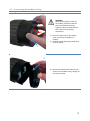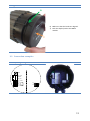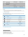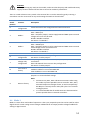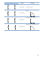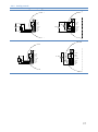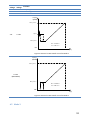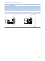
1
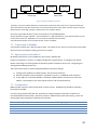
NMTC module
Functional profile and user manual
preliminary, 7340055, v4
2
6.1
Contents
6.2
Connecting to pump ad-hoc with a
cross over cable .........................................22
1 Symbols and conventions used in this
document ........................................................4
1.1
2
3
4
Bus topology ...................................21
Abbreviations and conventions .........4
7
Introduction.............................................5
6.3
Connecting to pump via router .......26
6.4
Pump configuration over Ethernet ..27
Modbus .................................................31
7.1
Modbus related interface ...............31
2.1
System diagram ................................5
7.2
Bus topology ...................................31
2.2
Specifications ...................................5
7.3
Connection to Modbus ...................32
Module layout .........................................7
7.4
Speed, parity and address ...............32
3.1
Connection considerations ...............8
7.5
Termination ....................................32
3.2
Connecting the module wiring ..........9
7.6
Register block overview ..................33
3.3
Connection examples .....................11
7.7
NMTC Configuration register block .33
Control modes and priorities .................12
7.8
NMTC Status register block .............34
4.1
Priority of settings ..........................12
7.9
Pump control register block ............34
4.2
Control variables.............................13
7.10
Pump status register block ..............36
4.3
Module mode selection ..................13
7.11
Pump data register block ................38
4.4
Mode 1 ...........................................14
7.12 Modbus telegrams and function
codes 39
4.4.1
Digital (switch) control ............15
4.4.2
Analog control ........................17
8
Fault finding...........................................39
Mode 2 ...........................................18
8.1
Error codes .....................................39
5
Relay output ..........................................20
8.2
Communication faults .....................41
6
Ethernet.................................................21
4.5
WARNING!
Prior to installation and commissioning, read these instructions first. Installation and operation must
comply with local regulations.
WARNING!
Installation and use of this product requires experience and knowledge of this or similar products.
Persons with reduced physical, mental or sensory capabilities must not use this product, unless
properly instructed and supervised. Children must not be allowed to play with this product.
3
1 Symbols and conventions used in this document
WARNING!
Denotes that a failure to observe those instructions might cause damage to equipment or pose danger
to the user.
NOTE: - Gives additional tips or instructions that might ease the job and ensure proper operation.
1.1 Abbreviations and conventions
Abbreviation
Baud, Baud rate
CRC
Ethernet
H
LED
Modbus
NMTC
Q
RTU
RS-485
Description
Serial communication speed, in bits per second including start, parity and stop bits.
Cyclic Redundancy Check, additional bytes used to confirm valid data transmission.
IEEE 802.3, mostly referring to 10BASE-T RJ-45 connector present on board.
Differential pressure, often called Head.
Light Emitting Diode.
A serial communication protocol used for device automation and remote access.
NMT pump Communication module.
Pump flow or flow rate.
Remote Terminal Unit.
Multi drop serial network wiring, used to transfer Modbus data.
For Modbus use, this manual assumes that the reader is familiar with commissioning and configuring of
Modbus devices. It is also assumed that an existing Modbus RTU network on RS-485 wiring with
Modbus master is present.
For Ethernet and web interface use, this manual assumes that the reader knows how to configure or
already has preconfigured Ethernet network.
For use of analog signals and relay output signals, external controller needs to be configured and used.
Proper operating mode must also be selected for the module.
NOTE:
•
•
•
•
•
Data in this document are subject to change.
Actual implementation might differ by pump model and software revision.
Make sure you are using the right manual for your product.
Verify proper operation in the final system.
Manufacturer cannot be held responsible for problems caused either directly or indirectly by
the use of information in this manual.
4
2 Introduction
This manual describes the NMTC module for NMT range of pumps that is either integrated or separately
available. This module is used for various remote control applications, including:
•
•
•
•
•
Remote on/off
Analog 0..10V voltage control
Modbus remote control
Status relay feedback
Web access over Ethernet
It is suitable for medium size NMT pumps, 90-440W of rated power.
2.1 System diagram
There are several possible connection configurations. Not all functions can be used simultaneously.
on/off + 0..10V + relay output
Modbus RTU + Relay output
Ethernet + on/off + 0..10V
Modbus RTU + Ethernet
Ethernet + on/off + relay output
…
2.2 Specifications
The table below is an overview of NMTC specifications. For details, please refer to appropriate
sections of this manual.
General data
Ambient humidity
Dimensions [∅ x H]
Power supply and
connection
<95 % relative, noncondensing
112 mm x 32 (45) mm
5V@500mA supplied
by the pump
Also see appropriate pump data for other
ambient specifications.
Dimensions without glands.
6-pin connector further extended for display.
5
Modbus specifications
Data protocol
Modbus RTU
Modbus connector
Screwless terminals
Modbus connection
type
Modbus wire
configuration
Communication
transceiver
Maximum cable
length
2+1 pins. See section 7.3 “Connection to
Modbus”.
RS-485
Two-wire + common
Integrated, 1/8 of
standard load
1200 m
Conductors: A, B and COM (Common).
See section 7.3 “Connection to Modbus”.
Connect either via passive taps or daisy chain.
See section 7.5 “Termination”.
Default is 245, settable over Modbus. See
section 7.4 “Speed, parity and address”.
Line termination is not integrated. For low
speed/short distance, termination can be
omitted. Otherwise, terminate the line
externally on both ends.
Slave address
1-247
Line termination
Not present
Supported
transmission speeds
1200, 2400, 4800,
9600, 19200, 38400
baud
Settable over Modbus register [default=19200].
Start bit
1
Fixed.
Data bits
8
Stop bits
1 or 2
Fixed.
1 stop bit minimum, up to 2 when parity not
enabled [default=1]
Parity bit
Even/odd/none
Modbus visual
diagnostics
Maximum number of
Modbus devices
Maximum Modbus
packet size
Isolation
LED2
247
[default=Even]
Flashing yellow when data reception detected.
Combined (OR) with Ethernet ACT function.
Limited by possible Modbus addresses to 247.
1/8 nominal load enables 256 devices.
256 bytes
Including address (1) and CRC (2) bytes.
Common ground
(COM) with SET1,
SET2 and SET3.
Modbus shares common ground with other
signals.
Ethernet specifications
Ethernet connector
Connection type and
services
Default IP address
Ethernet visual
diagnostics
RJ-45
10BASE-T, 10Mbit/s connection.
- Web server (port 80)
- Firmware update over web interface
- Optional Modbus RTU over TCP/IP
192.168.0.245
192.168.0.246 for right twin pump.
Slowly blinking when module is powered,
LED1 / LINK
permanently lid when link established.
Flashing yellow when data reception detected.
LED2 / ACT
Combined (OR) with Modbus data reception
indication.
6
Mode selection switch
Adjustment
10 position rotary
switch
Position read at power-on.
Used for relay configuration and module
configuration reset.
Analog signals (SET1, SET2, SET3)
Input voltage range
Output voltage
range
Input resistance
Output current sink
range
-1..32VDC
~100k
When used as input.
When used as output. 5mA max. load allowed
per output.
0.5mA load is added for most configurations.
0..33mA (4-20mA)
Current sink to COM if configured as output.
0..12V
Relay specifications
Connection type
Rating
Screwless terminals
- 230 VAC, 3 A, AC1
- 32 VDC, 3 A
Potential free changeover contact.
3 Module layout
23
6 78
45
9 1
0
MODE
LED1 / LINK
ETHERNET
Modbus signal
LED2 / ACT
B/D RS-485
A/D +
SET1 / RUN
COM / 0V
SET2 / MAX
SET3 / FB
NC
C
NO
ALARM
RUN MAX
Figure 1: Typical module connection
7
Terminal
Description
Designation
Mode selection rotary switch. Used to configure mode of operation for the circuit. See
MODE
section 4.3 “Module mode selection”.
Slowly blinking when module is powered.
LED1 / LINK Blinking fast when Modbus Error
Permanently lid when Ethernet link established.
Ethernet
10BASE-T RJ-45 connector.
LED2 / ACT Indicates Ethernet activity or Modbus activity.
B/DRS-485 negative data signal for Modbus.
A/D+
RS-485 positive data signal for Modbus.
SET1 / RUN Control signal 1.
COM / 0V
RS-485 common and analog input common (ground).
SET2 / MAX Control signal 2.
SET3 / FB
Control signal 3.
NC
Normally closed relay contact. Opens when relay is active.
C
Relay common contact.
NO / OK
Normally open relay contact. Closes when relay is active.
3.1 Connection considerations
•
•
•
•
All cables connected must be heat-resistant to at least +85°C.
All cables connected must be installed in accordance with EN 60204-1.
All wires to the communications module must be connected to the terminals or cut. No loose wiring
permitted.
If voltages over 24VAC/DC are possible on NO, C, NC terminals:
WARNING!
•
•
Wires should be routed so no wire crosses the center barrier.
Relay cable (NO, C, NC) must be separated from all other wiring with reinforced
insulation. Cable outer layer must not be stripped longer than 15mm. See “Cabling
preparation” below.
Cabling preparation
max. 15 mm
0.25 - 1 mm2
Cable for the screwless terminals should
be prepared as shown on the left.
8(7-10)mm
Tools
2.4mm wide flat-bladed screwdriver is
needed to press the terminal spring
while inserting the cable.
Same tool is also used to rotate the
Mode switch.
8
3.2 Connecting the module wiring
Opening the cover
1.
WARNING!
Before performing any work on
the module, make sure that the
pump and module electricity
supply has been switched off and
that it cannot be accidently
switched on.
2.
1) Press two top hooks on the display
panel. Use flat tip screwdriver if
needed.
2) Simultaneously pull display panel away
from the pump.
1.
3.
3) Disconnect display panel cable to ease
access to the module wiring. Wiring can
now be connected.
9
Closing the cover
4.
WARNING!
Before performing any work on the
module, make sure that the pump
and module electricity supply has
been switched off and that it
cannot be accidently switched on.
4) Reconnect display panel cable.
5) Make sure that the position tab and
position slot are aligned.
5.
10
Closing the cover
6.
6) Make sure that the hooks are aligned.
7) Push the display back to the NMTC
module.
7.
3.3 Connection examples
Default (factory) configuration
23
6 78
45
9 1
0
MODE
LED1 / LINK
ETHERNET
LED2 / ACT
B/D RS-485
A/D +
SET1 / RUN
COM / 0V
SET2 / MAX
SET3/ FB
NC
C
NO
11
Relay and Modbus connection
23
6 78
45
9 1
0
MODE
LED1 / LINK
ETHERNET
Modbus signal
LED2 / ACT
B/D RS-485
A/D +
SET1 / RUN
COM / 0V
SET2 / MAX
SET3 / FB
NC
C
NO
ALARM
RUN MAX
Relay and Ethernet connection
23
6 78
45
9 1
0
MODE
LED1 / LINK
ETHERNET
LED2 / ACT
B/D RS-485
A/D +
SET1 / RUN
COM / 0V
SET2 / MAX
SET3/ FB
NC
C
NO
NOTE: To maintain pump IP protection, the
network cable should be pulled through the gland
inlet and then crimped to a connector.
4 Control modes and priorities
4.1 Priority of settings
Several signals will influence the pump operation. For this reason, settings have priorities as shown in
the table below. If two or more functions are active at the same time, the one with highest priority will
take precedence.
12
Priority
1
2
3
4
5
6
7
8
Pump control panel &
Ethernet settings
Stop (OFF)
Night mode active2
Max. RPM (Hi)
Setpoint setting 4
External signals 1
Modbus control
Min. curve4
Stop (Run not active)
Max. curve4
Setpoint setting4
Stop3
Setpoint setting 3
Examples:
•
•
Stop on the pump display panel will stop the pump, regardless of external setpoint.
If External Run input is inactive, the pump cannot be started over Modbus, but can be set to max
RPM on the display panel.
4.2 Control variables
Pump will respond to external controls according to selected pump operating mode. Consult proper
pump operating manual for explanation.
Symbol
A
Regulation mode
Auto mode
Module setpoint controls:
(RUN only)
Proportional pressure
Maximum head
Constant pressure
Maximum head
Constant speed
Free 5
Night mode6
Speed
(RPM)
(Web interface only)
(RUN only)
4.3 Module mode selection
1
Not all inputs are available in all modes.
External and Modbus Stop signals become active in night mode. Due to possible confusion, use of night mode is
discouraged while using external control.
3
Only available when pump is bus controlled.
4
Not available when pump is bus controlled.
5
Multiple limits can be set. Not available on all pumps.
6
Night mode is not independent regulation mode.
2
13
WARNING!
Before performing any work on the module, make sure that the pump and module electricity
supply has been switched off and that it cannot be accidently switched on.
There is a mode selection rotary switch in the terminal box. It can be rotated by gently inserting a
screwdriver into the arrow mark on top and rotating the switch to desired value.
Mode
switch
position
Function
Description
0
Free
configuration
Terminal functions are configured over Ethernet interface.
1
Mode 1
2
Mode 2
3..5
RESERVED
Show relay
configuration
6
7
Change relay
configuration
8
Twin reset to
factory
SET1 = RUN input
SET2 = MAX input
SET3 = FB (10.5V) output, used to supply RUN and MAX inputs. External
voltage source can also be used.
RS-485 = Modbus interface.
See section “4.4 Mode 1”.
SET1 = RUN input
SET2 = SPEED input
SET3 = FB (10.5V) output, used to supply RUN and MAX inputs. External
5-24V voltage source can also be used.
RS-485 = Modbus interface
See section “4.5 Mode 2”.
Reserved for future or customer specific use.
LED1 and LED2 will show relay configuration.
See section “5 Relay output”.
Relay configuration will be increased (0->1, 1->2, 2->0) when electricity
is turned on.
LED1 and LED2 will show current relay configuration.
See section “5 Relay output”.
Same as Mode 9, with exception of:
module IP address is set to 192.168.0.246
Twin IP address is set to 192.168.0.245
This mode will set communication interface to default values. Main
purpose is to restore default settings.
NOTE:
•
9
Reset to factory
•
Disconnect any SET1, SET2 and SET3 connections when using
this mode to prevent possible harm to controller. SET1, SET2,
SET3 will output test voltages of 10V, 7V and 5V respectively.
RS-485 port is actively driven. Relay will cycle. This is used for
testing purposes.
It is recommended that all module wires are disconnected to
prevent possible harm to external controllers.
4.4 Mode 1
Mode 1 is most often used mode of operation. It has 2 pre-prepared inputs that can be used for either
digital control or with analog control voltages. Additional 10.5V output provides voltage feedback for
analog or digital control.
14
Terminal
designation
SET1 / RUN
COM / 0V
SET2 / MAX
SET3 / FB
Signal function
RUN input. Signal load 0.5mA.
Common ground for voltage input.
MAX input. Signal load 0.5mA
10.5V feedback voltage for SET1 and SET2.
4.4.1 Digital (switch) control
Mode 1 connection configurations (switch)
23
6 78
45
9 1
0
MODE
LED1 / LINK
ETHERNET
LED2 / ACT
RUN
MAX
B/D RS-485
A/D +
SET1 / RUN
COM / 0V
SET2 / MAX
SET3/ FB
15
Contact position
RUN
MAX
Function
Stop the pump
Description
The pump is stopped
The pump will run with internal
setpoint
Start the pump
H
Q
The pump will run with minimal speed
for selected regulation mode
Minimum curve
H
Q
The pump will run with maximum
speed form selected regulation mode
Maximum curve
H
Q
16
4.4.2 Analog control
Mode 1 connection configurations (analog)
23
23
45
MODE
9 1
9 1
0
0
LED1 / LINK
ETHERNET
ETHERNET
LED2 / ACT
23
LED2 / ACT
0...10V
B/D RS-485
A/D +
SET1 / RUN
COM / 0V
SET2 / MAX
SET3/ FB
23
45
9 1
9 1
0
RUN
6 78
6 78
45
MODE
LED1 / LINK
B/D RS-485
A/D +
SET1 / RUN
COM / 0V
SET2 / MAX
SET3/ FB
RUN
6 78
6 78
45
MODE
0
MODE
LED1 / LINK
LED1 / LINK
ETHERNET
ETHERNET
LED2 / ACT
B/D RS-485
A/D +
SET1 / RUN
COM / 0V
SET2 / MAX
SET3/ FB
0...10V
LED2 / ACT
B/D RS-485
A/D +
SET1 / RUN
COM / 0V
SET2 / MAX
SET3/ FB
17
RUN
voltage
<2V
>3V
<2V
MAX
voltage
<1V
<1V
2..10V
Function
Pump stopped
Internal regulation
Minimum curve
H [m] /
n[RPM]
Hmax / nmax
>3V
2..10V
H/ n
Hmin / nmin
Hmin = 15% Hmax
nmin = 25% nmax
Off
1
2
10
3
U[V]
Figure 2: External 2..10V transfer curve for Mode 1
H [m] /
n[RPM]
Hmax / nmax
0..10V
(RUN+MAX)
Hmin / nmin
Hmin = 15% Hmax
nmin = 25% nmax
Off
1
2
3
10
U[V]
Figure 3: External 0..10V transfer curve for Mode 1
4.5 Mode 2
18
Mode 2 is used for external 0..10V voltage control.
Terminal
designation
SET1 / RUN
COM / 0V
SET2 / MAX
SET3 / FB
Signal function
RUN input. Signal load 0.5mA.
Common ground for voltage input.
SPEED input. Signal load 0.5mA
10.5V feedback voltage for SET1 and SET2.
Mode 2 connection configurations
23
23
45
MODE
9 1
9 1
0
0
MODE
LED1 / LINK
LED1 / LINK
ETHERNET
ETHERNET
LED2 / ACT
RUN
6 78
6 78
45
B/D RS-485
A/D +
SET1 / RUN
COM / 0V
SET2 / MAX
SET3/ FB
RUN
0...10V
LED2 / ACT
B/D RS-485
A/D +
SET1 / RUN
COM / 0V
SET2 / MAX
SET3/ FB
19
RUN
MAX
voltage voltage
<2V
0..10V
Function
Pump stopped.
H [m] /
n[RPM]
Hmax / nmax
>3V
0..10V
Hmin = 15% Hmax
nmin = 25% nmax
Hmin / nmin
Off
0.5
10
U[V]
Figure 4: External 0..10V transfer curve for Mode 2
5 Relay output
Terminal
designation
MODE
LED1 / LINK
LED2 / ACT
NC
C
NO / OK
Terminal description
Mode selection rotary switch. Used to show and configure mode of operation for relay.
Slowly blinking when module is powered, permanently lid when link established7.
Flashing yellow when data reception detected. Combined (OR) with Modbus data
reception indication7.
Normally closed relay contact. Opens when relay is active.
Relay common contact.
Normally open relay contact. Closes when relay is active.
The module contains one status relay, used to signal pump operation or malfunction. See table below
for functionality.
Relay
configuration
Output
status
Description
Relay
position
LED status 7
LED 1 LED 2
7
When mode Mode 6 or Mode 7 is selected, LED1 and LED2 will show relay configuration. See section “4.3
Module mode selection”
LED is on
LED is off
20
Error
[default]
0
1
Only active when the pump is powered
up and detects a problem with
operation.
NO
C
NC
NO
C
NC
NO
C
NC
NO
C
The relay signal is active when the pump
is ready for operation.
Ready
The relay signal is active as long as the
pump is operating. If the pump comes to
Operation
a stop or an error occurs, relay will
deactivate.
2
NC
-
Relay output not active.
Relay configuration number can be modified by either the web interface, Modbus register 012 or the
Mode switch.
6 Ethernet
Terminal
designation
MODE
LED1 / LINK
Ethernet
LED2 / ACT
Description
Can be used to reset network configuration
Slowly blinking when module is powered, permanently lid when link established.
10BASE-T RJ-45 connector.
Indicates Ethernet activity or Modbus reception.
The communications module has a built in web server which allows you to access your pump directly to
an existing Ethernet connection. Direct connection to a computer is also possible with a cross over
cable.
The web server uses HTML pages to set/view:
•
•
•
•
•
•
Regulation mode settings
Regulation parameters (power, RPM, head, flow, efficiency)
Relay settings
External control inputs
Current and previews error
Pump statistics (power consumption, run time and other).
6.1 Bus topology
21
Ethernet connection topologies
Figure 5: connecting to a computer with a cross-over cable
Figure 6: connecting to a network via router
6.2 Connecting to pump ad-hoc with a cross over cable
Connecting directly to a computer
USE CROSSOVER CABLE
These instructions are made for Microsoft Windows 7. You can connect the pump using any other OS
with a set IP address when connecting directly to a computer or any other device with a web browser
when connecting via a local network.
Requirements:
•
•
Computer with an internet browser (Chrome, Internet explorer, Firefox, Netscape, Safari,
Mosaic, Opera…) if connecting directly or device with a internet browser.
Ethernet crossover cable or Ethernet patch cable
Setting a local IP address:
1. Open your start menu and
then your „Control Panel“
22
2. Select „Network and Internet“
3.Open „Network and Sharing
Center“
23
4. Select „Change adapter
settings“
5. Right click on your wired
„Local Area Connection“ and
select „Properties“
24
6. Select „Internet Protocol
Version 4(TCP/IPv4)“ and select
„Properties“
8. Type in IP address
„192.168.0.XXX“, where XXX can
be any number from 2 to 244.
Subnet mask will be
automatically inserted. Select OK,
to confirm
9.Open your web browser
25
10. Type „nmtpump/“* in your
address bar**
11. You are now connected to
the pump
*or „192.168.0.245/“
**If connecting to a duplex pump
the right pumps has
„nmtpump/“(„or
192.168.0.245/“) and the left
„nmtpump2/“(„ or
192.168.0.246/“)
6.3 Connecting to pump via router
Connecting via a router
Requirements:
•
•
•
Ethernet patch cable
Device with an internet browser that can connect to a local network (computer, mobile
phone…)
Router
1. Connect your computer with your router.
Open your command line by typing cmd in windows search.
2. Then type „ipconfig“ in to the
command line
3. Look for IPV4 Address under
the network adapter that you
are currently using(wireless or
wired)
26
4. Connect your computer to the NMT pump, as described previous chapter.
5. Open your network page on
the pump and type in the first
three set of numbers of your ip
address that you got on the last
slide under „Pump IP address“
and press save.
Change according to your
network configuration
6. Connect the pump and router with an Ethernet patch cable
7. Open your web browser
9. Type „nmtpump/“* in your
address bar**
10. You are now connected to
the pump
*or „192.168.0.245/“
**If connecting to a duplex
pump the right pumps has
„nmtpump/“(„or
192.168.0.245/“) and the left
„nmtpump2/“(„ or
192.168.0.246/“)
6.4 Pump configuration over Ethernet
Monitor and adjust the NMT pump via the web pages
When you are connected to the pump and enter the settings page you see that it has 5 subpages:
•
•
•
•
•
Overview
Pump
Network
Log
Help
27
Overview Page:
The Overview page is opened when you enter the NMT web pages. You can monitor the NMT pump on
this page. Current operation parameters, pump temperature, control status and statistics are all
displayed in this section.
On the top right side of the page you can find the Refresh the view option. Using it you can decide
whether to automatically refresh every 3, every 30 seconds or to never refresh the Overview page.
Below, pump parameters are displayed in the following order:
•
•
•
•
Operation: Here, various pump operation parameters are shown, which display the current
measured or estimated (calculated) value. Next to the measured/estimated value, the user set
value is displayed in brackets.
Temperatures: The pumps temperature, measured on its heatsink and the motor status is displayed
here. If the temperature in the motor is too high, HOT will be displayed next to the Motor
parameter and the pump will automatically lower its power. The same will happen if the heatsink
temperature rises over the set limit.
Statistics: Various pump statistics data are displayed here.
Control: The status of the digital input control signals, relay status and the twin pump mode status
are all displayed here. The latter tells us if the monitored pump is connected with a second one in
the twin pump mode. The first two parameters are described in a separate manual.
Pump page:
28
This page is used to adjust the values of various pump parameters. On the basis of these user input
parameters, the pump will automatically regulate itself. On the top right side of the page you can find
the Regulation settings column.
The settings are in the following order (from top to bottom):
•
•
Limit head (Hmax): sets the maximum output head (differential
pressure).
Hmax proportional: sets the percentage of proportionality
between head and flow. 0% proportionality sets the Q-H curve to
constant pressure. Here the pressure doesn‘t change with flow,
there is no proportionality. X% proportionality sets the Q-H curve
to proportional pressure. This value determines the percentage of
pressure fall in relation to Hmax. Example: Limit head value (Hmax)
is set to 10 m and Hmax proportional is set to 50%. As a result the Q
–H curve is going to start at 5 m and rise in a straight line until it
reaches 10 m. After that point, it will follow the unregulated curve.
See the graph on the right for the shape of the Q-H curve if Limit
head or Hmax proportional is set.
•
Limit RPM: sets the maximum RPM of the pump. Comparing to
the unregulated curve, the Q-H curve scales down. RPM
limiting is recommended when you want to change the curve.
This sort of regulating is similar to a manual adjustable pump.
•
Limit power: sets the maximum power of the pump. When
limiting power the Q-H curve scales down and its slope
gradually decreases
•
Switch on the relay
•
Input 1
29
•
Input 2
You can combine different settings (i.e.: Limit Power and Limit Head) and by doing that, shape the Q-H
curve to your liking.
On the bottom right side of the page three buttons are located: SAVE, TEST and RESTORE. The SAVE
button is used to save the current set values into permanent memory, while the TEST button is used to
apply changes to the pump without saving the set values into memory (only to check how possible
changes affect the pump). The RESTORE button retrieves the saved settings from memory.
Network page:
This page is used for adjusting the network settings of the pump.
You can change the following values:
•
•
•
•
•
Pump IP address
Subnet mask
Default gateway
NetBIOS name
Twin mode with IP
The SAVE, TEST and RESTORE buttons work in the same way as on the Pump page.
Log Page
This page is used to monitor and check if the pump is reporting any errors (Errors are also displayed by
the pumps LED light). The following data is displayed here:
-
Current error
-
Last error (the last detected error)
30
-
Startup diagnosis (shows a chain of numbers and represents information for service personnel)
In the Current error and Last error row, next to the error number there is a link, which redirects you to
the reference error list.
Error Page
Here, error descriptions are given for the corresponding blink/error code. Next to the descriptions,
probable causes and solutions to the problem are given. See user manual for error descriptions
Help Page
This page redirects you to www.imp-pumps.com, where software updates and manuals will be
available.
7 Modbus
7.1 Modbus related interface
Designation
MODE
LED2 / ACT
B/DA/D+
COM/0V
Description
Can be used to reset network configuration
Indicates Ethernet activity or Modbus reception.
RS-485 negative data signal for Modbus.
RS-485 positive data signal for Modbus.
RS-485 common and analog input common (ground).
7.2 Bus topology
NMTC is a Modbus slave, connected directly to a Modbus RTU network. Connection can be made in
either daisy chain style (if cabling allows such a connection) or a limited length passive tap. Schematic
example is in Figure 7.
31
Slave 1
Master
Slave 3
Daisy chain
Line
termination
Line
termination
Passive tap
Slave 2
Figure 7: Example of Modbus network
Typically, only one master device is connected to the serial bus, and one or several slaves are
also connected to the bus. Slaves do not communicate with each other and will never transmit
data without receiving a proper request from the master device.
Up to 32 single load devices can be connected to one RS-485 Modbus
system without using a repeater. As this module is a 1/8 load device, up to 256 modules can be
connected to the bus. Repeaters can be used to extend the maximum
transmission distance and increase device count if needed.
7.3 Connection to Modbus
A screened, twisted-pair cable should be used. The cable screen must be connected to the COM
terminal and connected to safety ground at one point.
7.4 Speed, parity and address
By default, each device is set to 19200-E-1 (even parity), address 245.
Properly set registers in section “7.7 NMTC Configuration register block” to configure each device
before connecting it to existing network. Optionally power each device one by one, configuring the
settings before adding another one.
There are several ways to restore forgotten Modbus connection settings:
1) Configure the module over Web interface. See section 6 “Ethernet”.
2) Reset the module to factory defaults. See Mode 9, section “4.3 Module mode selection”.
3) If only address is unknown, Modbus “broadcast” (0x00) address can be used to write new
address. Use carefully as the value will be written to all connected devices.
7.5 Termination
NMTC module contains neither termination nor bias circuitry. RS-485 wiring should be externally
terminated if needed.
For short wiring and/or low baud rate, interface can operate without termination. However it is
recommended that termination (~150 ohm resistor) is added on both ends of bus wiring. There are
wiring length limits regarding to speed and termination:
Maximum speed [baud]
38400
9600
19200
38400
Maximum cable length [m]
1200, terminated cable
1200
500
250
32
NOTE: Any branch/derivative cable is considered unterminated. Keep them short, below 250m
combined for maximum speed and reliability.
7.6 Register block overview
NMTC Modbus RTU registers are grouped in the following register blocks:
Start
address
Register block
Readable/Writeable Description
001
NMTC
configuration
R/W
021
NMTC status
R
101
Pump control
R/W
Configuration of the NMTC
module.
Status registers for the NMTC
module.
Pump control registers.
201
Pump status
R
Status data from the pump.
301
Pump data
R
Measured data from the pump.
All addresses contain 16 bit (one Word) registers. Some are bit interpreted while others are
combined for a 32 bit value.
NOTE: All register addresses are 1-based. Address 001 is thus transmitted over bus as 0x0000.
7.7 NMTC Configuration register block
Registers in this block are read with either function codes 0x03 or 0x04. They can be written as
holding registers with function codes 0x06 and 0x10.
NOTE: All values in this block are stored in nonvolatile memory immediately after write.
NOTE: See section “4.3 Module mode selection” an use Mode 8 or 9 to restore default settings if
you cannot access the controller after writing to these registers.
33
Address
Register name
Range
001
SlaveDelay
0..10000 1 ms
002
003
RESERVED
ModbusAddress 1..247
1
004
BitRate
1
005..
008
RESERVED
009
Parity
0..2
1
010
StopBits
1..2
2
011
RESERVED
012
RelayControl
0..5
0..2
Resolution
1
Description
Delay in milliseconds for slave reply. This delay
will be added to every Modbus reply
[default = 0].
Modbus address [default = 245].
Modbus transmission speed enumeration.
0 = 1200 baud
1 = 2400 baud
2 = 4800 baud
3 = 9600 baud
4 = 19200 baud [default]
5 = 38400 baud
Parity setting to be used for communication.
0 = No parity
1 = Even parity [default]
2 = Odd parity
Stop bits used for communication. 2 stop
bits will only be used when “Parity” is set to
0.
1 = 1 stop bit [default]
2 = 2 stop bits
Configures module relay output.
0 = indicates fault
1 = indicates pump ready
2 = indicates pump operation
See section “5 Relay output”.
7.8 NMTC Status register block
Registers in this block are read with either function codes 0x03 or 0x04. They are readonly. This block can be used for various kinds of fault finding.
Address
021..
022
023
024..
029
Register name
Resolution
Description
0.1
Module software version
1
Product version
[32x for NMTC module, x denotes hardware revision]
0.1
Module software version
[10 = 1.0]
RESERVED
SoftwareVersion
RESERVED
030
ProductVersion
031
RESERVED
032
SoftwareVersion
7.9 Pump control register block
Registers in this block are read with either function codes 0x03 or 0x04. They can be written as
holding registers with function codes 0x06 and 0x10.
34
Address
Register name
Range
b0:
RemoteAccess
101
ControlReg
b1:
OnOffReq
b2..15:
RESERVED
102
Description
Control bit that sets local or remote control.
Setting this bit will enable pump control over
Modbus.
0 = Local
1 = Remote (controlled by Modbus master).
Control bit that switches the pump on or off.
0 = Off (stop)
1 = On (start).
Alternative Control mode. Use of register 108 is
preferred.
Sets the control mode enumeration.
0 = ConstantRPM
1 = ConstantRPM
3 = ConstantHead
4 = ConstantHead
5 = ConstantHead
6 = ProportionalHead
128 = AutoHeadMode
AltControlMode
NOTE: values outside this range reserved.
103
OperationMode
RESERVED
104
SetPoint
0..
10000
105
RelayControl
0..2
See section “5 Relay output”.
106..107 RESERVED
108
ControlMode
Sets desired pump setpoint.
0 will stop the pump. 10000 will set the pump to
maximum output for desired mode.
Values outside of valid range will cause the pump
to operate with front panel set values.
Configures relay output.
0 = indicates fault
1 = indicates pump ready
2 = indicates pump operation
0..3
Sets the pump control mode.
0 = AutoHeadMode (Automatic head mode)
1 = ProportionalHead (Head proportional to flow)
2 = ConstantHead (Head is kept constant)
3 = ConstantRPM (Speed is kept constant)
NOTE: values outside this range reserved.
See section “4.2 Control variables” for exact
parameter to be controlled.
35
7.10 Pump status register block
Registers in this block can be read by means of function codes 0x03 and/or 0x04. They are
read-only.
36
Address
Register name
StatusReg
b0..b5:
RESERVED
b6: Rotation
b7: RESERVED
Bit 8:
AccessMode
Bit 9: IsOn
201
Bit 10: Error
Bit 11:
RESERVED
Bit 12:
RESERVED
Bit 13:
NearMaxSpeed
Bit 14:
RESERVED
Bit 15:
NearMinSpeed
202
RESERVED
203
ControlMode
204
RESERVED
205
ErrorCode1
206
ErrorCode2
207
ErrorCode3
Description
Indicates if the pump is rotating (running) or not.
0 = No rotation
1 = Rotation.
Indicates if the pump is locally or remotely controlled.
0 = Local (a source with higher priority controls the pump)
1 = Remote (controlled by Modbus master).
Indicates if the pump is on or off.
0 = Off
1 = On
It not necessarily indicate rotation as an error might stop the
pump.
Indicates if there is a problem with proper operation.
0 = No problem
1 = Error present.
Pump might still run.
Indicates if the pump is running near maximum speed.
0 = No
1 = Yes.
This flag is set when power or speed is over 95% of rated maximum.
Indicates if the pump is running near minimum speed.
0 = No
1 = Yes.
This flag is set when speed falls below 1/3 of rated maximum.
(TBD)
Indicates the actual control mode.
0 = ConstantRPM
1 = ConstantRPM
3 = ConstantHead
4 = ConstantHead
5 = ConstantHead
6 = ProportionalHead
128 = AutoHeadMode.
Current first error code.
0 - when pump is operating without problems.
This value will always be non-zero when there is an error present.
See section “9.1 Error codes” for code details.
Second error code. Non-zero when there is more than one error.
See section “9.1 Error codes” for code details.
Third error code. Non-zero when there is more than two errors.
See section “9.1 Error codes” for code details.
37
Address
208
Register name
ControlMode
Description
Indicates the actual control mode.
0 = AutoHeadMode (Automatic head mode)
1 = ProportionalHead (Head proportional to flow)
2 = ConstantHead (Head is kept constant)
3 = ConstantRPM (Speed is kept constant).
NOTE: values outside this range reserved.
See section “4.2 Control variables” for exact parameter to be
controlled.
7.11 Pump data register block
Registers in this block can be read by means of function codes 0x03 and/or 0x04.
They are read-only.
Modbus
address
Register name
301
Head
0.01 m
302
303
304
Flow
Efficiency
Speed
0.1 m3/h
0.01 %
1 rpm
305
Frequency
0.1 Hz
306..307
RESERVED
308
ActualSetPoint
0..10000 0.01%
309..311
312
313
314..317
RESERVED
PowerHI
PowerLO
RESERVED
Indicates actual setpoint of the pump.
(-1 for internal pump regulation). tbd
0..232
1W
Total power consumption of the
system.
318
CircuitTemp
0.01 °C
Power electronics hotspot
temperature.
319
MotorTemp
0.01 °C
Motor compartment temperature.
320..321
RESERVED
322
LiquidTemp
0.01 °C
Liquid temperature.
323..326
327
328
329
330
331
332
333
RESERVED
OperationTimeHI
OperationTimeLO
TotalPoweredTimeHI
TotalPoweredTimeLO
RESERVED
EnergyHI
EnergyLO
1 hour
Total operation time (above zero
speed) of the pump. 8
1 hour
Total power-on time of the module.8
1 kWh
Total energy consumption of the
system.8
8
Range
-5500..
16000
-5500..
16000
-5500..
16000
Resolution
Description
Pump head estimation in meters of
water column.
Pump flow estimation.
Estimated pump efficiency.
Motor speed.
Motor frequency
[100.0Hz for 3000rpm and 4 pole
motor].
Not available on all models.
38
7.12 Modbus telegrams and function codes
8 Fault finding
8.1 Error codes
The following codes will show up on display panel and on the appropriate Modbus registers to help you
diagnose the cause of improper operation.
39
Error code
E1x
Description
Load errors
E10 (drY)
Low motor load
E11
High motor load
E2x
Protection active
E22 (hot)
Converter temperature limit
E23
Converter temperature protection
E24
Converter overcurrent
E25
Overvoltage
E26
Undervoltage
E3x
Pump errors
E31
Software motor protection active
E4x
Device specific error codes
E40
General frequency converter error
E42 (LEd)
LED faulty
E43 (con)
Communications failed
E44
DC link current offset
E45
Motor temperature outside limits
E46
Circuit temperature outside limits
E47
Voltage reference outside limits.
E48
15V outside limits
E49
Test load does not match
E5x
Motor error codes
E51
Motor parameters out of range
Probable cause
Low load detected. Pump is
running dry.
Motor might be faulty or
viscous medium is present.
Circuit is too hot and power
was reduced to less than 2/3 of
rated power.
Circuit is too hot to run, pump
stopped.
Hardware overcurrent
protection triggered.
Line voltage is too high.
Line voltage is too low for
proper operation.
Average motor current was too
high, pump load is much higher
than expected.
Electrical circuitry did not pass
self-test.
One of the display segment
diodes is faulty (open/short).
Display board does not detect
proper connection to main
board, but power supply is
present.
Voltage on DC link shunt (R34)
not in expected range.
During MFG. TEST, this is 10k,
1% resistor for 10..30C
During operation, expected
values are -55°C..150°C.
During MFG. TEST, this is
0..50°C.
During operation, expected
values are -55°C..150°C.
Comparison between internal
references does not match.
15V supply not 15V.
No test load detected or
current measurement does not
work properly (MFG. TEST).
Motor does not behave as
expected.
40
8.2 Communication faults
(tbd)
41