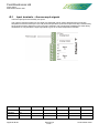
1
Field 5000
Alarm Monitor Unit
User Manual
V1.0
Field Electronics Ltd
5000 Alarm Monitor Unit
Contents
Overview ............................................................................. Section 1
Hardware ............................................................................. Section 2
HMI Operation..................................................................... Section 3
Screen Navigation .............................................................. Section 4
Alarms ............................................................................. Appendix A
User Wiring ..................................................................... Appendix B
Revision
1
Date
25/11/2010
Originator
HP
Approved
LA
Title Page.doc
Field Electronics Ltd
5000 Alarm Monitor Unit
Section 1 - Table of Contents
1
Overview ................................................................................................................................................................ 2
Revision
1
Date
25/11/2010
Originator
HP
Approved
LA
Section 1.doc
Section 1.1
Issue 1
25 November 2010
Field Electronics Ltd
5000 Alarm Monitor Unit
1
Overview
The 5000 alarm monitoring system uses a HMI touch screen panel to interface with the hardware configuration and
commissioning parameters, to monitor and display the connected signal values and to display and record alarm
activity. This manual has been prepared to aid and assist in installing and using the equipment.
Revision
1
Date
25/11/2010
Originator
HP
Approved
LA
Section 1.doc
Section 1.2
Issue 1
25 November 2010
Field Electronics Ltd
5000 Alarm Monitor Unit
Section 2 - Table of Contents
2
Hardware ............................................................................................................................................................... 2
2.1
User Connections (see figure 2.1) ................................................................................................................... 3
2.1.1
Power ...................................................................................................................................................... 3
2.1.2
Common Alarm Outputs ......................................................................................................................... 4
2.1.3
USB ......................................................................................................................................................... 4
2.1.4
Serial Communications ........................................................................................................................... 4
2.1.5
User Wiring ............................................................................................................................................. 5
2.2
User Indicators ................................................................................................................................................. 6
2.2.1
Alarm Indicators ...................................................................................................................................... 6
2.2.2
Heartbeat Indicator.................................................................................................................................. 6
2.2.3
Communications Activity Indicator .......................................................................................................... 6
Revision
1
Date
25/11/2010
Originator
HP
Approved
LA
Section 2.doc
Section 2.1
Issue 1
25 November 2010
Field Electronics Ltd
5000 Alarm Monitor Unit
2
Hardware
The basic 5000 instrument supports up to 6 analogue monitor channels in a single chassis. It is also available in
larger chassis that support 12 and 24 channnels.
Each channel is capable of interfacing a wide range of input signal types from mV and thermocouples, resistance,
thermistors and RTD devices through volts and mA inputs. Linearisation (TCs, RTDs etc) is performed by the
individual channel controller as is input scaling and ranging. Selection of the input type is performed via the HMI
and requires no hardware changes to the input circuit other than the physical input connections (resistance inputs
require a bridge circuit supply, and mA inputs require a burden resistance).
LEDs
Relay
A
Relay
B
Relays
Common
Alarm
Relays
(F100)
Retran
Process
Input
Channel
1
LEDs
Relays
Retran
Process
Input
Channel
up to 24
max
Internal
RS485 Comms
24Vdc Bus
HMI User
Interface
PSU
240/120Vac
Back-up
PSU
24Vdc
USB
Modbus
Comms
Figure 1: Series 5000 Alarm Monitor System Schematic.
Revision
1
Date
25/11/2010
Originator
HP
Approved
LA
Section 2.doc
Section 2.2
Issue 1
25 November 2010
Field Electronics Ltd
5000 Alarm Monitor Unit
2.1
User Connections (see figure 2.1)
All instrument user wiring and connections are accessible from the rear of the instrument. Field wiring uses 2part connectors to simplify maintenance.
Figure 2.1: 5000 Unit Rear Terminals – 6 channel chassis.
2.1.1
Power
The 5000 unit uses 240Vac mains power as its primary source. This is connected via a plug-in main cable
using a switched IEC connector at the rear of the unit. This is fitted with a 1.25A fuse (Farnell: 136-0830)
The internal 24Vdc power supply is distributed via the F1 and F2 fuses. These are both 500mA rated.
Fuse F1 protects the HMI panel. 20mm / 500mA. Anti-surge (Farnell: 112-3206)
Fuse F2 protects the IO cards. 20mm / 500mA. Anti-surge (Farnell: 112-3206)
Revision
1
Date
25/11/2010
Originator
HP
Approved
LA
Section 2.doc
Section 2.3
Issue 1
25 November 2010
Field Electronics Ltd
5000 Alarm Monitor Unit
2.1.2
Common Alarm Outputs
Each system has two common relay outputs available which can be driven by any selected alarm signals.
These alarms are defined as global or common alarms and the active alarm signals are set up from the HMI
panel and are driven by the HMI panel.
These common alarm signals are non-latching and respond only to the actual alarm (non-latching) signals
from the individual input channels.
The common alarms can be configured as a ‘True Alarm with re-flash’ or as a klaxon output.
i)
True Alarm with re-flash
This sequence has advantages when used in conjunction with an annunciator panel, data logging or
telemetry system, since the common relay outputs always show the true overall system status. The Common
Alarm relays only reset when all system alarm indications designated for common relay action are normal
and therefore there is no user reset function. This alarm is always NON-LATCHING.
After the first alarm, subsequent alarms are indicated by a 1/2 second toggling of the common relay to the
normal state, which is sufficient to communicate such further alarms to any downstream system (not yet
implemented).
ii)
Klaxon mode
This is a latching sequence with manual reset and is designed for use with a local audible warning. The
common alarm relays are reset by operation of the ALARM ACK key on the front panel, regardless of alarm
status on the system. It follows that the relay output cannot be relied upon to indicate the overall alarm
status.
2.1.3
USB
The HMI is programmed using a USB download cable. Also, it is intended to allow archiving of alarm states
and to back-up loop configurations, to a memory stick. This port allows both the download cable to be
installed without dismantling the instrument, and also allows the insertion of a memory stick.
2.1.4
Serial Communications
The 9-way ‘D’ connector situated below the USB port allows the user to connect to the loop comms circuit if
the HMI comms is disabled. Using a PC based tool, the loops can be configured via this port without having
to resort to using the HMI.
Revision
1
Date
25/11/2010
Originator
HP
Approved
LA
Section 2.doc
Section 2.4
Issue 1
25 November 2010
Field Electronics Ltd
5000 Alarm Monitor Unit
2.1.5
User Wiring
Each channel has a number of terminals dedicated to its input and output
requirements. There are 2 sets of channel connections per plug-in board as
each circuit board supports 2 channels. Figure 2.2 describes the terminal
assignment of a single circuit board (2 x analogue monitor channels).
Note that although the physical terminal layout is mirrored, the sense of the
input and output terminals is NOT mirrored – the analogue input and output
+ve terminals are always above the corresponding –ve terminals, and the
relay connections are grouped in threes with the change-over connection the
lowest of the three terminals.
Revision
1
Date
25/11/2010
Originator
HP
Approved
LA
Section 2.doc
Section 2.5
Issue 1
25 November 2010
Field Electronics Ltd
5000 Alarm Monitor Unit
2.2
User Indicators
Although the HMI monitors and displays the input signal value and
alarm activity, each loop has 2 x alarm indication LEDs as well as a
process heartbeat and communications activity LEDs. These
indicators are driven independently of the HMI and do not require
the HMI to work.
2.2.1
Alarm Indicators
The alarm LEDs reflect the actual alarm status of each channel
and can be on, flashing or fast flashing dependent on the
particular alarm configuration.
2.2.2
Heartbeat Indicator
During normal operation, this LED will flash ON once every 2
seconds for a period of 200mS.
If any of the configuration settings have been changed and the
changes not yet confirmed (written to EEROM), the indicator
LED flash sequence will be inverted. It will return to normal
behaviour when either an EEROM write is requested, or the unit
is power cycled. In the latter case, all changes will be reversed
and the old EEROM configuration re-instated.
2.2.3
Communications Activity Indicator
This LED is driven by the channel processor ‘transmit enable’ signal and will flash ‘ON’ whenever a
transmission occurs. As the Modbus protocol is a master/slave protocol, and the channel processor behaves
as a communications slave, this will only occur when the channel processor responds to a data request
issued from the HMI. This is a useful diagnostic feature indicating the scanning communication sequence
activity.
Revision
1
Date
25/11/2010
Originator
HP
Approved
LA
Section 2.doc
Section 2.6
Issue 1
25 November 2010
Field Electronics Ltd
5000 Alarm Monitor Unit
Section 3 - Table of Contents
3
HMI Operation ....................................................................................................................................................... 2
3.1
Button Descriptions .......................................................................................................................................... 2
3.2
Start-up Splash Screen.................................................................................................................................... 3
3.3
Overview Screen ............................................................................................................................................. 3
3.4
Detailed View Screen ...................................................................................................................................... 4
3.5
Password Entry Screen ................................................................................................................................... 4
3.6
Configuration Menu Screen ............................................................................................................................. 5
3.7
System Screens ............................................................................................................................................... 5
3.8
Input Type Configuration Screens ................................................................................................................... 7
3.9
Alarms Configuration Screen ........................................................................................................................... 8
3.10
Tag Setting Screen ....................................................................................................................................10
Revision
1
Date
25/11/2010
Originator
HP
Approved
LA
Section 3.doc
Section 3.1
Issue 1
25 November 2010
Field Electronics Ltd
5000 Alarm Monitor Unit
3
HMI Operation
The HMI screen is the main interface with the 5000 alarm monitoring system and allows access to all
commissioning and configuration areas of each analogue input channel. The following sections are concerned
primarily with the navigation and operation of the HMI panel.
3.1
Button Descriptions
A number of button icons are used throughout the HMI screens. Most of them are self-explanatory but for
completeness, they are listed here.
Home Button
Touching this icon, when it appears, will automatically switch the HMI back to the ‘Overview’ screen.
Back Button
Returns the HMI back to the previous screen.
Next Button
Switches to the next screen in a sequence.
Config Read Button
Displayed on the ‘Detail’ screen. This opens a pop-up window showing the channel configuration
information. This information is ‘read only’.
Accept Button
Only visible if a loop parameter has been changed. This allows the operator to send any changes made
down to the channel processor. Changes will be implemented immediately but will not be permanent.
Reject Button
Only visible if a loop parameter has been changed.
This allows the operator to abandon any changes made and to revert back to the original settings.
EEROM Write Button
Only visible if changes have been made and accepted. Touching this button will force the processor
channel being edited to ‘write’ its configuration data to EEROM making it permanent.
Configuration Entry Button
Button allows the user to enter the configuration area of the HMI. As this area includes sensitive
configuration parameters that, if changed, could cause problems, the area is password protected.
Revision
1
Date
25/11/2010
Originator
HP
Approved
LA
Section 3.doc
Section 3.2
Issue 1
25 November 2010
Field Electronics Ltd
5000 Alarm Monitor Unit
3.2
Start-up Splash Screen
On initial power-up, the HMI will display its operating system start-up sequence
before starting the 5000 interface application. This can be some several seconds
before the application start-up ‘splash’ screen is seen.
Once the 5000 application starts, the ‘splash’ screen will display for 3 seconds
before the default ‘overview’ screen is switched to.
The ‘splash’ screen shows details of the currently installed HMI firmware along
with its creation date. The Field Electronics contact details are also displayed.
3.3
Overview Screen
This is the default view of the 5000 HMI. It displays the 6/12/24 monitored signal
values and the current alarm status. The user defined channel ‘tag’ string is also
displayed although in truncated form for the 12 and 24 channel screens.
The user can view the current alarm status of the system by viewing the ‘Alarm
List’ screen using the touch button at the lower right-hand corner of the screen.
Individual alarm conditions can be acknowledged from this screen by touching
the 2 x 2 indication panel to the right of each channel tag and value details. A
pop-up window is displayed with the acknowledge option buttons.
Touching anywhere to the left of the alarm array will switch to the detailed view of
that channel.
Revision
1
Date
25/11/2010
Originator
HP
Approved
LA
Section 3.doc
Section 3.3
Issue 1
25 November 2010
Field Electronics Ltd
5000 Alarm Monitor Unit
3.4
Detailed View Screen
Touching the tag or value area on the overview screen will switch the view to the
‘Detail’ page. This page shows the channel tag string (full), measured value and
the channel’s alarm status as shown on the overview page. It also displays the 2x
threshold alarm setpoints, the 2x ROC alarm setpoints, the alarm deadband and
the alarm delay parameters.
The channel ‘alarm acknowledge’ can be issued from this screen by touching the
2 x 2 alarm status indicator to give access to the pop-up window.
All of these alarm parameters can be altered by the user. Simply touch the
parameter display box to pop-up an entry keypad then enter the required
parameter value.
When a value has been altered, the ‘Accept’ and ‘Reject’ buttons will appear.
Touching the ‘Reject’ button will return the displayed values back to what they were before the edit started.
These additional buttons will then disappear.
To accept the changes, touch the ‘Accept’ button. This will write the changes to the selected channel processor
and extinguish the ‘Accept’ and ‘Reject’ buttons. The ‘Confirm’ button will appear.
To make the changes permanent, this button MUST be pressed. This forces the changes to be written into
EEROM by the channel processor. Until this is done, changes made will persist only until the unit is power
cycled, at which point, the previous values will be read back out of EEROM during the power-up sequence.
3.4.1
Configuration Read
A pop-up window displays the current input configuration including input and sensor type, the measured
value display engineering units and, if fitted, the analogue output calibration settings.
3.5
Password Entry Screen
If the ‘Password Entry’ button on the ‘Detail View’ screen is pressed, the user will
be presented with the ‘Password Entry’ screen. Further access will be denied if
the password is not entered correctly.
Once entered correctly, the password will remain active for at least 300 seconds
– being reset back to 300 seconds on any key action made within the
configuration area. This does allow the user to exit the configuration area,
change the channel to be edited, and to re-enter the configuration area without
the need to continually re-enter the password.
If the user does not re-enter the configuration area for a period greater than this
300 seconds, the password will again be requested next time entry is attempted.
Revision
1
Date
25/11/2010
Originator
HP
Approved
LA
Section 3.doc
Section 3.4
Issue 1
25 November 2010
Field Electronics Ltd
5000 Alarm Monitor Unit
3.6
Configuration Menu Screen
This menu screen allows operator access to a number of configuration screens
that allow the modification of system and channel specific settings.
3.7
System Screens
This is a series of screens allowing the used to alter certain system wide settings.
Common Alarm Allocation Screens
This screen is used to assign which alarm signals are to be used to drive the
common alarm outputs. There are two similar screens – one for each common
alarm channel. Each channel generates 4 alarm signals and any/all of these
alarm signals can be individually assigned to the common alarm simply by
toggling the indicated channel. When assigned, the alarm signal displays ‘On’. It
is possible to assign the same alarm signal to both common alarm channels.
Once a change has been made, the ‘Accept’ and ‘Reject’ buttons will appear.
Touching the ‘Reject’ button will abort any changes made and revert back to the
previously saved setting.
Touching the ‘Accept’ button will confirm the changes and write them to the
EEROM of the common relay module.
Communications Control Screen
This screen allows the user to control the HMI access to individual channels.
Each channel can be individually enabled or disabled by touching the screen to
toggle the enable flag on/off.
Additionally, the user can unconditionally enable or disable all channel
communications using the two global buttons.
The ‘Reject’ and ‘Accept’ buttons behave in the same way as for the common
alarms above.
Revision
1
Date
25/11/2010
Originator
HP
Approved
LA
Section 3.doc
Section 3.5
Issue 1
25 November 2010
Field Electronics Ltd
5000 Alarm Monitor Unit
Calibrate Analogue Output Screen
If the analogue output daughterboard is fitted on any of the monitor channels, this
screen allows the user to set up the output calibration. This output signal gives a
linear retransmission of the input signals scaled between the MVMin and MVMax
parameters. To simplify the calibration process this screen displays the current
channel measured value.
Two calibration values can be adjusted – the ‘Gain’ parameter adjusts the range
of the output signal – normally 12 bit or 4095 counts – by reducing this output
scaling by up to 255 counts.
The ‘Offset’ parameter can be set to any value between 0.0% and 25.5%
allowing the simple implementation of a 20% pedestal to give, say, a 4-20mA
output.
New Password Entry Screen
If the system password needs to be altered, this screen allows the operator to
enter a new password value. The password is entered in plain text (not hidden).
When ‘Accepted’, the new password value is implemented and its value is written
to the common relay module EEROM.
Revision
1
Date
25/11/2010
Originator
HP
Approved
LA
Section 3.doc
Section 3.6
Issue 1
25 November 2010
Field Electronics Ltd
5000 Alarm Monitor Unit
3.8
Input Type Configuration Screens
The input of each analogue channel can be individually defined to match the
connected transducer. The screen allows the selection of :Transducer type – linear, thermocouple, resistance input.
Sensor type – input linear range, tc type, RTD type.
Display range – input minimum and input maximum.
Displayed value units - °C, mA, % etc.
When a setting has been altered, the ‘Accept’ and ‘Reject’ buttons will appear.
Touching the ‘Reject’ button will return the displayed settings back to what they
were before the edit started. These additional buttons will then disappear.
To accept the changes, touch the ‘Accept’ button. This will write the changes to
the selected channel processor and extinguish the ‘Accept’ and ‘Reject’ buttons. The ‘Confirm’ button will
appear.
To make the changes permanent, this button MUST be pressed. This forces the changes to be written into
EEROM by the channel processor. Until this is done, changes made will persist only until the unit is power
cycled at which point, the previous values will be read back out of EEROM during the power-up sequence.
3.8.1
CJC Calibration Screen
If the input type selected is ‘TC’, an additional calibration screen becomes
available. Touching the screen header panel will switch the view to give the
CJC calibration screen.
3.8.2
RTD Calibration Screen
If the input type selected is ‘RTD’, an additional calibration screen becomes
available. Touching the screen header panel will switch the view to give the
RTD calibration screen
Revision
1
Date
25/11/2010
Originator
HP
Approved
LA
Section 3.doc
Section 3.7
Issue 1
25 November 2010
Field Electronics Ltd
5000 Alarm Monitor Unit
3.9
Alarms Configuration Screen
The 5000 series alarm unit monitors the connected analogue signals alarm
conditions according to each alarm configuration settings. This screen allows the
user to set up each alarm channel according to the system requirement. Each
option can be toggled simply by touching the screen area of that setting.
3.9.1
Alarm Action
Each alarm channel can be enabled or disabled as required.
i)
Alarm Off
This option disables all alarm operations of the particular alarm
channel. All other selected options will be ignored and the relay output
will switch to its ‘no alarm’ state.
The associated ‘Rate-of-Change’ alarm will also be disabled.
ii)
Alarm On
This option enables all selected alarm options including the ‘Rate-of-Change’ alarm.
3.9.2
Alarm Types
Each monitored analogue input can be assigned up to four alarm conditions - two threshold alarms plus two
rate-of-change alarms.
i)
High Alarm
Each alarm channel can be configured as a threshold HIGH alarm monitor.
When configured as a threshold HIGH alarm, an alarm condition will be indicated whenever the
measured value (MV) exceeds the associated HIGH alarm setpoint. The alarm condition will persist
until the MV falls below this setpoint minus the alarm deadband (DB) setting. This prevents the alarm
switching between the active and inactive states when close to the threshold alarm setpoint.
ii)
Low Alarm
Each alarm channel can be configured as a threshold LOW alarm monitor.
When configured as a threshold LOW alarm, an alarm condition will be indicated whenever the
measured value (MV) falls below the associated LOW alarm setpoint. The alarm condition will persist
until the MV rises above this setpoint plus the alarm DB setting. This prevents the alarm switching
between the active and inactive states when close to the threshold alarm setpoint.
Revision
1
Date
25/11/2010
Originator
HP
Approved
LA
Section 3.doc
Section 3.8
Issue 1
25 November 2010
Field Electronics Ltd
5000 Alarm Monitor Unit
3.9.3
Latching Alarms.
Each alarm can be configured as either a latching or non-latching alarm.
i)
Non-latching Alarm
A non-latching alarm will persist only while the actual alarm condition persists. As soon as the alarm
condition is resolved, the alarm condition will reset itself.
ii)
Latching Alarm
A latching alarm will activate as soon as an alarm condition is seen, but will require an external reset
(acknowledge) to reset the alarm – the status will persist after the actual condition has been resolved.
If the alarm acknowledge is received before the alarm condition is removed, the alarm condition will
persist until the alarm condition is resolved, at which point, the alarm condition will reset.
If the alarm acknowledge is received after the alarm condition has been resolved, the alarm condition
will reset immediately.
3.9.4
Flashing Alarms
Each alarm indicator can be made to flash to indicate a new (unacknowledged) alarm condition.
i)
No Flash
When an alarm condition is identified, the associated alarm LED will light. It will remain lit until the
alarm condition is resolved and, in the case of latching alarms, the condition is acknowledged.
ii)
Flashing
When an alarm condition is identified, the associated alarm LED will start to toggle ON/OFF on a one
second tick. The LED will continue to flash until the alarm condition is acknowledged at which point,
the LED will either switch to a solid ON state if the alarm condition still exists, or switch OFF if the
alarm condition has been cleared.
3.9.5
First-up Alarms
This allows the input processor to identify which of its 2 alarm channels was first to enter an alarm condition.
The ‘first-up’ alarm channel will ‘fast flash’ its associated indication LED. This option only has significance if
both alarms are configured as latching alarms.
i)
Normal
The input processor simply performs the alarm processing without reference the other alarm channel
status.
ii)
First-Up
When ‘First-Up’ is selected, the input processor will check the alarm status of both loops and flag the
‘First-Up’ alarm channel by fast flashing its indicator LED (indicator toggled ON/OFF on a 500mS tick
– twice the Flashing Alarm rate).
Revision
1
Date
25/11/2010
Originator
HP
Approved
LA
Section 3.doc
Section 3.9
Issue 1
25 November 2010
Field Electronics Ltd
5000 Alarm Monitor Unit
3.9.6
Alarm Relay Action
If the alarm channel has an assigned output relay fitted, the sense of the relay output in alarm can be
defined.
i)
Rly OFF
During normal (no alarm) conditions, the output relay is de-energised. Relay will energise (switch)
when an alarm condition is identified.
ii)
Rly ON
During normal (no alarm) conditions, the output relay is energised. Relay will de-energise (switch)
when an alarm condition is identified. The relay will also switch when power to the loop is lost.
3.9.7
Rate-of-Change Alarm
If an alarm channel is enabled, an additional rate-of-change (ROC) alarm is also be implemented which can
offer an ‘early warning’ of an impending threshold alarm condition. If the associated alarm is set to ‘Latch’,
the ROC alarm will also be latching.
The ROC alarm setpoints are set in ‘units per second’ change. Setting the ROC setpoint to zero effectively
disables the ROC alarm.
i)
Rate OFF
The associated ROC alarm is enabled but will not drive the alarm relay output. There ROC alarm
processing will only set the ROC software flags.
ii)
Rate ON
The associated ROC alarm is enabled and will drive the alarm relay output if an alarm condition is
identified. There ROC alarm processing will set the software ROC flags and hardware relay outputs.
3.10
Tag Setting Screen
Each analogue input can be assigned a user defined tag. This tag will be
displayed on the ‘Overview’ and ‘Detail’ screens. The tag can be up to 16
characters in length.
When the tag has been altered, the ‘Accept’ and ‘Reject’ buttons will appear.
Touching the ‘Reject’ button will return the displayed tag back to what it was
before the edit started. These additional buttons will disappear.
To accept the change, touch the ‘Accept’ button. This will write the tag to the
selected channel processor and extinguish the ‘Accept’ and ‘Reject’ buttons. The
‘Confirm’ button will appear.
To make the change permanent, this button MUST be pressed. This forces the
change to be written into EEROM by the channel processor. Until this is done,
change made will persist only until the unit is power cycled at which point, the
previous values will be read back out of EEROM during the power-up sequence.
Revision
1
Date
25/11/2010
Originator
HP
Approved
LA
Section 3.doc
Section 3.10
Issue 1
25 November 2010
Field Electronics Ltd
5000 Alarm Monitor Unit
Section 4 - Table of Contents
4
HMI Screen Navigation.......................................................................................................................................... 2
Revision
1
Date
25/11/2010
Originator
HP
Approved
LA
Section 4.doc
Section 4.1
Issue 1
25 November 2010
Field Electronics Ltd
5000 Alarm Monitor Unit
4
HMI Screen Navigation
The following diagrams describe the screen navigation of the 5000 Alarm Monitor HMI.
This page shows the screen
navigation options around the
data view screens.
Entry to the configuration
screens is shown towards the
bottom right-hand corner of
the page. This area is
password protected to prevent
unauthorised access.
The ‘Overview’ screen is the
default ‘Home’ screen and
shows an overview of the
parameter values and the
current alarm conditions. A
user defined ‘tag’ string can
be defined to give a more
meaningful description of the
parameter being monitored.
Individual loop information can
be viewed by touching the tag
or value area on the
‘Overview’ screen. This
screen shows the current
parameter value, the alarm
status and the loop tag of the
selected loop.
Additionally, the ‘Detail’ view
allows the modification of the
alarm setpoints, the ROC
setpoints, as well as the alarm
deadband and delay period.
The loop configuration can
also be viewed from this
screen via a pop-up window.
The current alarm event page is accessible from the ‘Overview’ screen. This screen lists all current alarm
conditions, the start time of the alarm event, and the time the alarm was acknowledged, if it has been
acknowledged.
A further alarm page shows the alarm history of the most recent alarm events.
Revision
1
Date
25/11/2010
Originator
HP
Approved
LA
Section 4.doc
Section 4.2
Issue 1
25 November 2010
Field Electronics Ltd
5000 Alarm Monitor Unit
The ‘Configuration’ screens consist
of a top level menu screen allowing
access to groups of related ‘set-up’
screens.
All ‘system’ related configuration
options can be accessed via the
‘System’ menu option.
The currently accessed loop can be
configured from the ‘Input Type’
menu option.
The alarm configuration of the
currently accessed loop can be
configured from the ‘Alarm Type’
menu option.
The currently accessed loop ‘Tag’
can be edited from the ‘Tag’ menu
option.
Revision
1
Date
25/11/2010
Originator
HP
Approved
LA
Section 4.doc
Section 4.3
Issue 1
25 November 2010
Field Electronics Ltd
Alarm Action
5000 Alarm Monitor Unit
Appendix A - Table of Contents
A
Alarms.................................................................................................................................................................... 2
A.1
Software ...................................................................................................................................................... 2
A.1.1
Alarm Action ............................................................................................................................................ 2
A.1.2
Alarm Types ............................................................................................................................................ 2
A.1.3
Latching Alarms. ..................................................................................................................................... 3
A.1.4
Flashing Alarms ...................................................................................................................................... 3
A.1.5
First-up Alarms ........................................................................................................................................ 3
A.1.6
Alarm Relay Action.................................................................................................................................. 4
A.1.7
Rate-of-Change Alarm ............................................................................................................................ 4
A.2
Alarm Hardware........................................................................................................................................... 5
A.2.1
True Alarm with re-flash .......................................................................................................................... 5
A.2.2
Klaxon mode ........................................................................................................................................... 6
Revision
1
Date
25/11/2010
Originator
HP
Approved
LA
Appendix A.doc
Section A.1
Issue 1
25 November 2010
Field Electronics Ltd
Alarm Action
5000 Alarm Monitor Unit
A
Alarms
The 5000 series alarm monitor enables the monitoring of up to 24 analogue signals, recording each alarm as a
time-stamped event. The user can view the current alarm status of the instrument as an alarm list showing all
currently active alarm states, and can also view the alarm history which includes the individual alarm recovery
timestamp.
A.1
Software
Each input channel supports two independent threshold alarms assigned to monitor that input status. Each
alarm channel can be configured to tailor its operation to suit the user application.
A.1.1 Alarm Action
Each alarm channel can be enabled or disabled as required.
i)
Alarm Off
This option disables all alarm operations of the particular alarm channel. All other selected options will
be ignored and the relay output will switch to its ‘no alarm’ state.
The associated ‘Rate-of-Change’ alarm will also be disabled.
ii)
Alarm On
This option enables all selected alarm options including the ‘Rate-of-Change’ alarm.
A.1.2 Alarm Types
Each monitored analogue input can be assigned up to four alarm conditions - two threshold alarms plus two
rate-of-change alarms.
i)
High Alarm
Each alarm channel can be configured as a threshold HIGH alarm monitor.
When configured as a threshold HIGH alarm, an alarm condition will be indicated whenever the
measured value (MV) exceeds the associated HIGH alarm setpoint. The alarm condition will persist
until the MV falls below this setpoint minus the alarm deadband (DB) setting. This prevents the alarm
switching between the active and inactive states when close to the threshold alarm setpoint.
ii)
Low Alarm
Each alarm channel can be configured as a threshold LOW alarm monitor.
When configured as a threshold LOW alarm, an alarm condition will be indicated whenever the
measured value (MV) falls below the associated LOW alarm setpoint. The alarm condition will persist
until the MV rises above this setpoint plus the alarm DB setting. This prevents the alarm switching
between the active and inactive states when close to the threshold alarm setpoint.
Revision
1
Date
25/11/2010
Originator
HP
Approved
LA
Appendix A.doc
Section A.2
Issue 1
25 November 2010
Field Electronics Ltd
Alarm Action
5000 Alarm Monitor Unit
A.1.3 Latching Alarms.
Each alarm can be configured as either a latching or non-latching alarm.
i)
Non-latching Alarm
A non-latching alarm will persist only while the actual alarm condition persists. As soon as the alarm
condition is resolved, the alarm condition will reset itself.
ii)
Latching Alarm
A latching alarm will activate as soon as an alarm condition is seen, but will require an external reset
(acknowledge) to reset the alarm – the status will persist after the actual condition has been resolved.
If the alarm acknowledge is received before the alarm condition is removed, the alarm condition will
persist until the alarm condition is resolved, at which point, the alarm condition will reset.
If the alarm acknowledge is received after the alarm condition has been resolved, the alarm condition
will reset immediately.
A.1.4 Flashing Alarms
Each alarm indicator can be made to flash to indicate a new (unacknowledged) alarm condition.
i)
No Flash
When an alarm condition is identified, the associated alarm LED will light. It will remain lit until the
alarm condition is resolved and, in the case of latching alarms, the condition is acknowledged.
ii)
Flashing
When an alarm condition is identified, the associated alarm LED will start to toggle ON/OFF on a one
second tick. The LED will continue to flash until the alarm condition is acknowledged at which point,
the LED will either switch to a solid ON state if the alarm condition still exists, or switch OFF if the
alarm condition has been cleared.
A.1.5 First-up Alarms
This allows the input processor to identify which of its 2 alarm channels was first to enter an alarm condition.
The ‘first-up’ alarm channel will ‘fast flash’ its associated indication LED. This option only has significance if
both alarms are configured as latching alarms.
i)
Normal
The input processor simply performs the alarm processing without reference the other alarm channel
status.
ii)
First-Up
When ‘First-Up’ is selected, the input processor will check the alarm status of both loops and flag the
‘First-Up’ alarm channel by fast flashing its indicator LED (indicator toggled ON/OFF on a 500mS tick
– twice the Flashing Alarm rate).
Revision
1
Date
25/11/2010
Originator
HP
Approved
LA
Appendix A.doc
Section A.3
Issue 1
25 November 2010
Field Electronics Ltd
Alarm Action
5000 Alarm Monitor Unit
A.1.6 Alarm Relay Action
If the alarm channel has an assigned output relay fitted, the sense of the relay output in alarm can be
defined.
i)
Rly OFF
During normal (no alarm) conditions, the output relay is de-energised. Relay will energise (switch)
when an alarm condition is identified.
ii)
Rly ON
During normal (no alarm) conditions, the output relay is energised. Relay will de-energise (switch)
when an alarm condition is identified. The relay will also switch when power to the loop is lost.
A.1.7 Rate-of-Change Alarm
If an alarm channel is enabled, an additional rate-of-change (ROC) alarm is also be implemented which can
offer an ‘early warning’ of an impending threshold alarm condition. If the associated alarm is set to ‘Latch’,
the ROC alarm will also be latching.
The ROC alarm setpoints are set in ‘units per second’ change. Setting the ROC setpoint to zero effectively
disables the ROC alarm.
i)
Rate OFF
The associated ROC alarm is enabled but will not drive the alarm relay output. There ROC alarm
processing will only set the ROC software flags.
ii)
Rate ON
The associated ROC alarm is enabled and will drive the alarm relay output if an alarm condition is
identified. There ROC alarm processing will set the software ROC flags and hardware relay outputs.
Revision
1
Date
25/11/2010
Originator
HP
Approved
LA
Appendix A.doc
Section A.4
Issue 1
25 November 2010
Field Electronics Ltd
Alarm Action
5000 Alarm Monitor Unit
A.2
Alarm Hardware
Each input module has two alarm channels with associated relay outputs. Each alarm relay has one set of
change-over contacts which are brought out to terminals at the back of the instrument for user wiring.
Additionally, a further two relay outputs are available which can be driven by any selected alarm signals. These
alarms are defined as global or common alarms and the active alarm signals are set up from the HMI panel.
These common alarm signals are non-latching and respond only to the actual alarm (non-latching) signals from
the individual input channels.
The common alarms can be configured as a ‘True Alarm with re-flash’ or as a klaxon output.
A.2.1 True Alarm with re-flash
This sequence has advantages when used in conjunction with an annunciator panel, data logging or
telemetry system, since the common relay outputs always show the true overall system status. The Common
Alarm relays only reset when all system alarm indications designated for common relay action are normal
and therefore there is no user reset function. This alarm is always NON-LATCHING.
After the first alarm, subsequent alarms are indicated by a 1/2 second toggling of the common relay to the
normal state, which is sufficient to communicate such further alarms to any downstream system (not yet
implemented).
Revision
1
Date
25/11/2010
Originator
HP
Approved
LA
Appendix A.doc
Section A.5
Issue 1
25 November 2010
Field Electronics Ltd
Alarm Action
5000 Alarm Monitor Unit
A.2.2 Klaxon mode
This is a latching sequence with manual reset and is designed for use with a local audible warning. The
common alarm relays are reset by operation of the ALARM ACK key on the front panel, regardless of alarm
status on the system. It follows that the relay output cannot be relied upon to indicate the overall alarm
status.
LEDs
Relay
A
Relay
B
Relays
Common
Alarm
Relays
(F100)
Retran
Process
Input
Channel
1
LEDs
Relays
Retran
Process
Input
Channel
up to 24
max
Internal
RS485 Comms
24Vdc Bus
HMI User
Interface
PSU
240/120Vac
Back-up
PSU
24Vdc
Modbus
Comms
Figure A.1:
Revision
1
Date
25/11/2010
Originator
HP
Approved
LA
Appendix A.doc
Series 5000 Alarm Monitor System Schematic.
Section A.6
Issue 1
25 November 2010
Field Electronics Ltd
Alarm Action
5000 Alarm Monitor Unit
Appendix B - Table of Contents
B
Terminal Connections ............................................................................................................................................ 2
B.1
Input terminals - Linear and non-linear voltage signals .............................................................................. 3
B.2
Input terminals – mA signals ....................................................................................................................... 4
B.3
Input terminals – thermocouple signals ....................................................................................................... 5
B.4
Input terminals – PRT signals ..................................................................................................................... 6
B.5
Input terminals – resistance ........................................................................................................................ 6
B.6
Output Terminals – volts and mA retransmission ....................................................................................... 7
B.7
Output Terminals – channel alarm relay output .......................................................................................... 8
B.8
Output Terminals – common alarms ........................................................................................................... 9
Revision
1
Date
25/11/2010
Originator
HP
Approved
LA
Appendix B.doc
Section B.1
Issue 1
25 November 2010
Field Electronics Ltd
Alarm Action
5000 Alarm Monitor Unit
B
Terminal Connections
The 5000 series monitors up to 24 analogue signals. System wiring is made to the rear of the instrument.
The diagram, below, describes the 6 channel 5006 unit terminals.
The instrument power connection is to the lower right of the diagram with the two system fuses, F1 and F2.
Above these items is the USB connection (currently used only for HMI f/w updates) and a 9-way male ‘D’ connector
giving supervisory access to the instrument (optional).
Moving left, the next block of terminals give connection to the system’s common alarm outputs (lower bank of 8
terminals).
Finally, the last 3 card slots can be populated with alarm monitor card – each card supports 2 fully independent
input channels – giving a total of 6 channels in this arrangement. The 12 and 24 channel instruments will be similar
to this 6 channel instrument but will support 6 and 12 monitor cards.
The connections on individual cards allow wiring of the input signal (3 terminals), the analogue retransmission
signal (2 terminals) and the 2 alarm relay outputs (6 terminals).
Rear Terminals of the 6-channel 5006 unit
The following pages describe how to wire the individual channels and the common alarms.
Revision
1
Date
25/11/2010
Originator
HP
Approved
LA
Appendix B.doc
Section B.2
Issue 1
25 November 2010
Field Electronics Ltd
Alarm Action
5000 Alarm Monitor Unit
B.1
Input terminals - Linear and non-linear voltage signals
Linear volt and mvolt inputs are connected directly as shown. Channel 1 input block is at the top of the
printed circuit board while channel 2 is at the bottom. However, the polarity of the terminals remains the
same that is the positive terminal is above the negative terminal for both channels.
Revision
1
Date
25/11/2010
Originator
HP
Approved
LA
Appendix B.doc
Section B.3
Issue 1
25 November 2010
Field Electronics Ltd
Alarm Action
5000 Alarm Monitor Unit
B.2
Input terminals – mA signals
The commonly used 4-20mA signal interface requires the addition of a 100Ω burden resistor. This should be
a high stability, high accuracy, ⅛ watt component. This converts the 20mA signal into a 2V signal.
The 4mA offset is processed in firmware.
Revision
1
Date
25/11/2010
Originator
HP
Approved
LA
Appendix B.doc
Section B.4
Issue 1
25 November 2010
Field Electronics Ltd
Alarm Action
5000 Alarm Monitor Unit
B.3
Input terminals – thermocouple signals
Thermocouple inputs are basically mV inputs.
The output of a thermocouple is a non-linear mV signal that can be used to determine the hot junction
temperature of the thermocouple. The cold junction temperature (instrument input terminals) is measured by
the channel processor whenever a TC input type is selected. This cold junction temperature is used during
linearization to compensate the input signal level to give an accurate temperature indication.
Revision
1
Date
25/11/2010
Originator
HP
Approved
LA
Appendix B.doc
Section B.5
Issue 1
25 November 2010
Field Electronics Ltd
Alarm Action
5000 Alarm Monitor Unit
B.4
Input terminals – PRT signals
Platinum Resistance Temperature sensors are a widely used temperature measurement device. They rely
on the variation in electrical resistance with temperature.
When the instrument is configured as a PRT input, the instrument re-configures its hardware input into a 3wire resistance bridge connection. This device does not support a 4-wire resistance connection.
The device supports a number of different resistance thermometer sensor types – not all based on platinum.
The circuit basically measures resistance then uses an internal linearization process to calculate the
temperature value.
B.5
Input terminals – resistance
As suggested, above, the PRT input is basically a resistance measuring circuit. When a resistance input type
is selected, the instrument performs the same measurement operations as for the PRT type inputs.
However, unlike the PRT measurement, the input value is expressed in Ohms (no linearization).
Revision
1
Date
25/11/2010
Originator
HP
Approved
LA
Appendix B.doc
Section B.6
Issue 1
25 November 2010
Field Electronics Ltd
Alarm Action
5000 Alarm Monitor Unit
B.6
Output Terminals – volts and mA retransmission
Each channel has an optional retransmission analogue output of the measured value. This output can be
either 0 – 10V or 4 – 20mA. The actual output range is a configuration option and is defined by the MVMin
and MVMax parameters.
Each retran output requires an additional daughterboard fitted to the processor printed circuit board. The
build of this daughterboard defines the output type – Volts or mA.
Revision
1
Date
25/11/2010
Originator
HP
Approved
LA
Appendix B.doc
Section B.7
Issue 1
25 November 2010
Field Electronics Ltd
Alarm Action
5000 Alarm Monitor Unit
B.7
Output Terminals – channel alarm relay output
Each channel supports two independent alarm outputs: ‘A’ and ‘B’. By default, these outputs will be supplied
as solid-state relay outputs. Alternatively, two change-over relays may be fitted if required.
The diagram shows the normal (unpowered) state of the relay outputs. Configuration options allow the user
to define the alarm sense of each relay individually.
Revision
1
Date
25/11/2010
Originator
HP
Approved
LA
Appendix B.doc
Section B.8
Issue 1
25 November 2010
Field Electronics Ltd
Alarm Action
5000 Alarm Monitor Unit
B.8
Output Terminals – common alarms
Additional to the channel alarm relays – 2 channels per board, 2 alarm relay outputs per channel – a further
2 relay outputs are available that can be used as global or common alarms. Each channel alarm condition
can be assigned to one or both common alarms.
The common alarm outputs are normally open contacts (unpowered). They will be configured to ‘close on
alarm’.
Revision
1
Date
25/11/2010
Originator
HP
Approved
LA
Appendix B.doc
Section B.9
Issue 1
25 November 2010