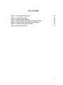
1
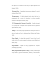
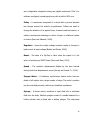
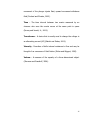
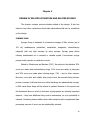
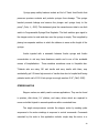
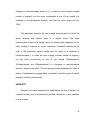
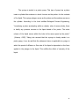
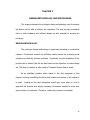
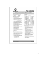
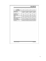
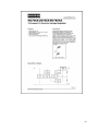
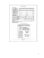
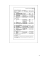
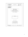
Programmable Syringe Flow Regulator By Margarette G. Castisimo Jessica Camille D. Docog Louisse Philipp P. Leocadio Raymond P. Pariñas Vincent S. Quitlong Jr. A Design Report Submitted to the School of Electrical Engineering, Electronics and Communications Engineering, and Computer Engineering in Partial Fulfillment of the Requirements for the Degree Bachelor of Science in Computer Engineering Mapua Institute of Technology October 2009 ii Acknowledgment The members of the group acknowledge the following without whose support would not make this design project possible: to Engr. Jocelyn F. Villaverde, our adviser; to Engr. Noel B. Linsangan, our Design II Professor; and to our families for their understanding when we were away from our homes doing this project; To numerous unnamed friends who wished to preserve their anonymities, for their support and inspiration; And above all, to our Almighty God whose infinite wisdom gave us the capability to come up with a design that our engineering colleagues could use. To all of you, our deepest appreciation and gratitude. Margarette G. Castisimo Jessica Camille D. Docog Louisse Philipp P. Leocadio Raymond P. Pariñas Vincent S. Quitlong Jr. iii TABLE OF CONTENTS TITLE PAGE i APPROVAL SHEET ii ACKNOWLEDGEMENT iii TABLE OF CONTENTS iv LIST OF TABLES vi LIST OF FIGURES vii ABSTRACT viii Chapter 1: DESIGN BACKGROUND AND INTRODUCTION 9 DESIGN SETTING STATEMENT OF THE PROBLEM OBJECTIVE OF THE DESIGN SIGNIFICANCE OF THE DESIGN CONCEPTUAL FRAMEWORK SCOPE AND DELIMITATION DEFINITION OF TERMS 9 10 10 11 12 12 14 Chapter 2: REVIEW OF RELATED LITERATURE AND RELATED STUDIES 18 Chapter 3: DESIGN METHODOLOGY AND PROCEDURES 22 DESIGN METHODOLOGY DESIGN PROCEDURE HARDWARE DESIGN 1. Block Diagram 2. Schematic Diagram 3. List of Materials 22 23 26 26 28 32 SOFTWARE DESIGN PROTOTYPE DEVELOPMENT 33 34 iv Chapter 4: TESTING, PRESENTATION, AND INTERPRETATION OF DATA Chapter 5: CONCLUSION AND RECOMMENDATION CONCLUSION RECOMMENDATION BIBLIOGRAPHY 36 44 44 45 46 APPENDICES Appendix Appendix Appendix Appendix Appendix A - List of Materials and Price Listings B - Data Sheets C - Program Listing D - User’s Manual E - Device Components 48 50 63 67 70 v LIST OF TABLES Table Table Table Table 3.1 4.1 4.2 4.3 List of Materials Time – Volume Accuracy Test Results Input – Output Comparison Test Results Cost Analysis 32 37 40 42 vi LIST OF FIGURES Figure Figure Figure Figure Figure Figure Figure 1.1 3.1 3.2 3.3 3.4 3.5 3.6 Conceptual Frameworks Design Procedures System Block Diagram Microcontroller Interface Schematic Diagram Stepper Motor Driver Schematic Diagram Power Supply Circuit Diagram System Flow Chart 12 23 26 28 30 31 33 vii ABSTRACT The Programmable Syringe Flow Regulator is a device that regulates a constant flow rate of the liquid depending on the specified time required for its use. This design is originated to develop an innovative way of using syringes common in the market to help those people in the medical field as well as researchers that will need this device on their experiments. The device is composed of helical screw, linear guide, aluminum bar and an angle bar that will hold the syringe and a stepper motor. Keywords: programmable, syringe, flow rate, regulator, microcontroller viii Chapter 1 DESIGN BACKGROUND AND INTRODUCTION This chapter discusses a brief introduction about the design; the problems and the objectives identified by the researchers; the significance of the study to its possible users; and the scope and delimitation of the design. DESIGN SETTING Syringes commonly available in the market nowadays are those we see in the hospitals that are used as a medical tool. Moreover, it can be used in researches since it is also a measuring tool used to transfer liquids from one container to another. It is manually operated resulting to inconstant force applied on the plunger thus having an irregular flow of liquid. This kind of manual operation of syringe when used in research development may lead to inappropriate results which is at far behind of what is being expected. The market today offers a wide variety of these types of syringes but the price is way higher than an individual can afford to. Also market-based products are already made products that cannot be modified or be customized on the way the consumer wants them to be. 9 STATEMENT OF THE PROBLEM Because of the fast changing technology people tend to search, if not, they develop equipment that will help them do their work conveniently and at the same time to come up with desirable results. Syringes that are commonly available in the market are manually operated, thus, resulting to irregular flow of liquid. Another problem is when a researcher conducting experiments involving liquid tests wants to have a device that will enable him to control a constant liquid flow rate thus, giving a more acceptable test results. OBJECTIVE OF THE DESIGN The main objective of the design is to create a programmable syringe flow regulator that can dispense solutions with varying viscosity. Listed below are the specific objectives of the research: 1. To show that the volume of different liquid dispensed in a given time is constant; and 2. To develop a low-cost programmable syringe flow regulator compared to market-based products. 10 SIGNIFICANCE OF THE STUDY Programmable Syringe Flow Regulator is a prototype that can be used in research – related experiments. It can be used in experiments needed in biomedical researches, in hospitals and even in school laboratories. This study will benefit researchers especially those on chemical or drug researches. The development of the programmable syringe regulator will help them make their tests and experiments be automated and achieve a more acceptable test results. Schools will also benefit on this innovation since it can be used in chemical laboratories. Economically, the country will benefit on this study since all materials used are bought locally which are quite cheap. Thus duplicating and making this device is easy. Users can be assured that the programmable syringe regulator is user friendly. 11 CONCEPTUAL FRAMEWORK INPUT PROCESS OUTPUT Liquid Solution Hardware and Software Programmable Syringe Flow Regulator Figure 1.1 Conceptual Framework The figure shows the concept of our design. The liquid is placed on the syringe then inserted in the bar. The user then enters the desired flow rate and time when the liquid is all dispersed. By pressing the start button, the inputted values are implemented and the helical screw is started to move that pushes the syringe until it reaches the other end of the aluminum bar and the syringe is empty. It informs the user if the process is done by its sound and pushes the syringe to its starting point. SCOPE AND DELIMITATIONS The device covers and delimits the following: Scope of the Design: 1. Flow rate ranges from 0.1 mL/min to 9.9 mL/min which are the minimum and maximum rates respectively. 2. It can output the desired rate of the user in one minute. 3. Syringe can be filled with liquid manually. 12 4. The device will still function regardless of its position. Delimitation of the Design: 1. The syringe flow regulator can only hold a 5cc syringe. 2. The syringe holder can only contain one syringe at a time. 3. The device has no scheduler wherein it does not automatically start and stop to run. 4. The device has no pause function and will continue its work until the liquid is completely consumed. 13 DEFINITION OF TERMS Buffer – Creates an output equal to the input. It also serves as a signal refresher to strengthen any weak signal output (Floyd, 2006). Calibrate – To check, adjust, or determine the graduations of a quantitative measuring instrument by comparison with a standard (Pyzdek and Keller, 2003). Delay – Change in an output in response to the change of an input occurs after a specified propagation delay (Mano and Kime, 2003). Driver – A small piece of software that tells the operating system and other software how to communicate with a piece of hardware (Mano and Kime, 2003). Flow Rate – The amount of fluid that flows in a given time (Sherman and Russikoff, 1996). Input – The signal or line going into a circuit; a signal that controls the operation of a circuit (Floyd, 2006). Keypad – Used to enter information to the computer (Mano and Kime, 2003). Liquid – The physical state of matter in which particles are held together but are free to move about. It has a definite volume but takes 14 the shape of the container in which they are placed (Sherman and Russikoff, 1996). Microcontroller – A specialized microprocessor designed for control functions (Floyd, 2006). Microprocessor – A digital integrated circuit device that can be programmed with a series of instructions to perform specified functions on data (Mano and Kime, 2003). PIC (Programmable Interrupt Controller) - Handles interrupts on a priority basis. It accepts service requests from the peripherals (Mano and Kime, 2003). Plunger – Part of the syringe responsible for creating the vacuum to draw up liquids and then to discharge them (Dorland and Rhodes, 2002). Power Supply – A system that converts AC current from the wall outlet into the DC currents required by electronic circuits (Bakshi and Godse, 2004). Programmable – Capable of being programmed for computer processing (Floyd, 2006). PSOC (Programmable System-on-Chip) – A family of mixed-signal arrays made by Cypress Semiconductor, featuring a microcontroller 15 and configurable integrated analog and digital peripherals. PSoC is a software configured, mixed-signal array with a built-in MCU core. Pulley – A mechanism composed of a wheel with a groove between two flanges around the wheel's circumference. Pulleys are used to change the direction of an applied force, transmit rotational motion, or realize a mechanical advantage in either a linear or rotational system of motion (Beer and Mazurek, 2008). Regulator – Keeps the output voltage constant inspite of changes in load current of input voltage (Bakshi and Godse, 2004). Reset – The state of a flip-flop or latch when the output is 0; the action of producing a RESET state (Mano and Kime, 2003). Speed – The particle’s displacement divided by the time interval during which that displacement occurs (Servay and Jewett, Jr., 2004). Stepper Motor – A brushless, synchronous electric motor that can divide a full rotation into a large number of steps. The motor's position can be controlled precisely, without any feedback mechanism. Syringe – A device used in medicine to inject fluid into or withdraw fluid from the body. Medical syringes consist of a needle attached to a hollow cylinder that is fitted with a sliding plunger. The downward 16 movement of the plunger injects fluid; upward movement withdraws fluid (Dorland and Rhodes, 2002). Time – The time interval between two events measured by an observer who sees the events occurs at the same point in space (Servay and Jewett, Jr., 2004). Transformer – A device that is mostly used to change the voltage in an alternating current (AC) (Bakshi and Godse, 2004). Viscosity - Describes a fluid's internal resistance to flow and may be thought of as a measure of fluid friction (Potter and Wiggert, 1990). Volume – A measure of the capacity of a three-dimensional object. (Sherman and Russikoff, 1996). 17 Chapter 2 REVIEW OF RELATED LITERATURE AND RELATED STUDIES This chapter contains previous studies related to the design. It also has citations from other researchers which state observations that can be considered on the design. SYRINGE PUMP Syringe Pump is dedicated to intravenous dosage of little volume (up to 100 ml) medicaments (antibiotics, anesthetics, analgesics, chemotherapy reagents) with very high accuracy by using syringes. Syringe pump allows infusing medicaments at a constant or variable speed. Conventional syringe pumps mostly operate in stand-alone mode. Stated by Markevicius and Navikas (2007), According to the statistics 39% errors are made while administering drugs, 10% errors are made in pharmacy and 38% errors are made when infusing drugs, 13% – due to other reasons. Moreover, very strict and reliable drug control must be ensured during infusion process, because if clinician does not notice that drugs are administered wrongly, in 98% cases these drugs will be infused to patient. Because of the reports and the statements above in which in this case, syringe pumps are critically important element – they have additional drug control mechanisms, so error probability is reduced. Combining human ability which takes decisions with computerized data processing, amount of errors can be substantially reduced. 18 Syringe pump safety features include an End of Travel Limit Switch that preserves precious contents and protects syringes from damage. “The syringe bracket prevents leakage and secures the plunger and syringe body to the pump” (John, L., 2005). This statement gives the researchers an idea to use limit switch in Programmable Syringe Flow Regulator. The limit switches give signal to the stepper motor to reset and stop once the syringe is empty. This is applied by placing two separate switches in which the distance is same as the length of the syringe. Insulin injected with a mismatch between Insulin syringe and Insulin concentration in vial may have disastrous results and is one of the avoidable causes of hospitalization. These mistakes sometimes occur in Hospitals also. “Patients who are using 100 unit insulin and carry insulin with them, may accidentally get 2.5 times high amount of insulin dose due to hospital staff using patients insulin vial of 100 U but syringe is wrongly used as 40 U” (Neff, 2008). STEPPER MOTOR Stepper motors are widely used in various applications. They can be found in printers, disk drives, X-Y plotters, and many others which are required to move controlled objects to accurate positions within nominated time. The single microprocessor controls the stepper motor by sending pulse sequences to the motor windings in response to control commands. Commands executed by the code in this application include: single step the motor in a 19 clockwise or counterclockwise direct ion (i. e. rotate the rotor through a certain number of degrees); run the motor continuously at one of four speeds in a clockwise or counterclockwise direction; and stop the motor (Kang and Qu, 1994). This application describes the use of single microprocessor to control the speed, direction and rotation angle of a stepper motor. This single microprocessor controls the stepper motor by sending pulse sequences to the motor winding in response to control commands. Commands executed by the code in this application include: single step the motor in a clockwise or counterclockwise (i. e. rotate the rotor through a certain number of degrees); run the motor continuously at one of four speeds (25steps/second, 100steps/second, and 400steps/second) in a clockwise or counterclockwise direction; and stop the motor. This is a general purpose application for which a degree of adjustment or program ability is required to meet the needs of specific processor end their performances. VISCOSITY Viscosity is the main parameter that characterizes the flow of liquids in an industrial process, and its measurement provides information on the resistance to flow in tubes. 20 The syringe is similar to a piston pump. This type of pump has a piston inside a cylinder-like container in which it serves as the pusher for the contents of the liquid. This syringe plunger serves as the piston and its container serves as the cylinder. According to the book entitled Biological Process Engineering, “considering a piston accelerating within a cylinder, when it moves slowly, there is hardly any pressure increase in the liquid ahead of the piston. The entire column of the liquid moves within the tube at the same speed as the piston” (Johnson, 1999). Taking into account that the syringe is closely similar to a piston pump, it can be said that the statement above is applicable to syringe in which the speed of diffusion or flow rate of the liquid is dependent on the force applied in the plunger to the liquid. This nullifies the effect of viscosity of the liquid. 21 CHAPTER 3 DESIGN METHODOLOGY AND PROCEDURES This chapter discusses the prototype design methodology used to develop the device and be able to achieve the objectives. The step by step procedures done on both hardware and software design are also essential to develop the prototype. DESIGN METHODOLOGY The prototype design methodology is patterned according to constructive research. Constructive research by definition mainly focuses on producing novel solutions to practically relevant problems. It gradually involves evaluation of the problem and a solution that fits the best based on the objectives or criteria being set. This kind of research is often used in Computer Science field of study. As an identified problem which stated in the first paragraph of this chapter, knowing something about the past models and designs of the system is a must. Looking at the past researches would give some idea on how to approach the problem and supply necessary information needed to arrive at a given solution or conclusion. Therefore, conducting research is inevitable. 22 DESIGN PROCEDURES START Statement of the Problem State Possible Solutions N Best/ Most Appropriate Solution? Y Creation of Project Plan Finalized Y Materials Gathering Project Design/ PCB Application N Plan? Prototype Testing Y Finalization Meet Requirements/ Objectives? N END Review Requirements/ Design Adjustments Figure 3.1 Design Procedures 23 In order to make the system developed, there are basic processes and tool that the proponents used in making the proposed system design. These processes are then taken step-by-step for guidelines in order to arrive at what is being set and expected. And those processes being used are the following: 1. Materials Gathering Since the project has already commercial implementations, it is assumed that all materials that will be used are already available in the local market. The best good option is to buy at the stores that sell in lowest prices but don’t compromise the quality and can stand at a long period of time. Location can be a factor to the prices, so going to places like Quiapo specifically in Raon part where a lot of the needed semiconductor goods needed are available. For component parts, stores like Alexan are of good choice. Also visit some mechanical shops for helical screw. 2. Design Creation/PCB Application After completing the materials needed and finalized the created project plan, actual implementation and PCB application are the next steps. In these steps, all theories and ideas will be put into reality through actual making of a working design prototype. Also, a thing like programming of the microcontroller (PIC and PSOC) is done. See item d. PCB application of the hardware implementation 24 part of this chapter to see the actual PCB implementation of the project. 3. Prototype Testing Since the prototype has been created, one is uncertain if the output of the prototype is correct or not even if it is already working. This can only be done by subjecting the designed system through series of test in determining if the output goes with the theories that have been applied and to what is the user has been expecting. This part also identifies the quality of work made and the coverage that it can cover as stated in the scope and delimitations in chapter 1. To see what are the testing methods being used, the next chapter discusses them. 25 HARDWARE DESIGN a. Block Diagram Controller Box PIC MCU PSOC (Buffer) White Box STEPPER MOTOR DRIVER STEPPER MOTOR POWER SUPPLY HELICAL SCREW (OUTPUT) KEYPAD (INPUT) Figure 3.2 System Block Diagram The Figure 3.2 from the previous page illustrates the block diagram of the system. The system is divided into main parts: a) Controller Box and b) White Box. The controller box which consists of the keypad, microcontroller (PIC and PSOC) and power supply serves as the main controller circuit, as the name implies, wherein the input is being processed. The user will be using the 0-9 digit keypad to enter flow rate which will be processed inside the PIC microcontroller. After sending the input, the PIC microcontroller will then make necessary computations needed in order to create an output. This output will be transferred first to the PSOC microcontroller in order to make the signal from the PIC 26 microcontroller gains strength. Another purpose of the PSOC microcontroller is to synchronize the stepper motor driver and PIC microcontroller due to clock timing issues between the two. The output from the PSOC microcontroller will serve as the input for the second part of the system which is the white box part. This white box serves as the output of the system that is composed of different parts such as stepper motor and its driver and the helical screw. The output from the PSOC microcontroller will be interpreted by the stepper motor driver for it to be able to make the stepper motor runs. The actions applied by the stepper motor will either turn the helical screw, where the syringe is attached, go back and forth. 27 b. Schematic Diagram Figure 3.3 Microcontroller Interface Schematic Diagram 28 Figure 3.3 shows the schematic diagram of the circuit. This gives a detailed illustration of how each circuit component is to be interconnected to the other. Due to space constraints, the researchers subdivided the schematic diagram into three separate picture illustrations. The first is denoted by figure 3.3, the system main design circuit. This part houses the microcontroller, P1C16F877A, connected to other components like the LCD screen display and keypad. The Figure 3.4 below gives the details about the interconnection of pins between the two main components contained in the figure illustration which are the stepper motor (circular shape) and its driver (rectangular shape). Then located on the driver’s left side are the pins that must be connected to microcontroller through figure 3.3. 29 STEPPER MOTOR DRIVER Motor +88.8 TO MCU INTERFACE ClkF ClkB Enbl Stepper Motor Control Supply 110VAC Figure 3.4 Stepper Motor Driver Schematic Diagram Figure 3.5 illustrates the system’s main power supply circuit diagram. It converts 22O V AC Voltage to 5 V DC Voltage for it to be usable to the circuit. 30 Figure 3.5 Power Supply Circuit Diagram 31 c. List of Materials QUANTITY (IN PCS.) MATERIAL 3 10K ohms resistor 1 1 LCD Monitor PIC16F877A 28/40-pin 8-bit CMOS Flash Microcontroller 1 CY8C29466-24PXI 24 Pin PSOC Microcontroller 1 1-9 Keypad 1 Stepper Motor Driver 1 Stepper Motor 1 Helical screw 1 Linear Guide 1 Angular Screw 1 220V to 12V Step Down Transformer 3 1nF Capacitor 2 3300 uF Capacitor 1 1K ohms Resistor 4 Diode 1 LM7805 3-Terminal 1A Positive Voltage Regulator 1 Black Plastic Case 1 Wooden Box Case 1 Plastic Glass Cover 1 5 CC Syringe Injection 10 ft. Wire Table 3.1 List of Materials Table 3.1 enumerates the different materials used in developing the Programmable Syringe Flow Regulator. Also included in the table are the quantities of the items used in the design. 32 SOFTWARE DESIGN SYSTEM FLOWCHART START System ON? N N Y Display RESET OK? Y Input Flow Rate N Start Operation Y Evaluate input/ Define speed of the stepper motor Stepper motor Running END Figure 3.6 System Flow Chart 33 Figure 3.6 from the previous page, shows the overall design flow chart of the software. It also illustrates at the same time what are the steps that the system will take accordingly. In brief summary, based on the figure shown, the system upon turning the power on a LCD screen will display a certain message about what flow rate that the user wanted. The user will decide whether the inputted flow rate is correct and want to start operation or not. In some cases, improper or incorrect inputs are entered but these can be solved by entering again the desired flow rate. After the system has received the input, it will be processed and analyzed by the program in the MCU. The output is expected after the MCU has successfully carried out the operation. This output varies accordingly to the input. 3. PROTOTYPE DEVELOPMENT Primarily the source of input of the system is the keypad with number 0-9. Its inputs A, B, C and D which are bit representations of each corresponding number and will proceed to the MCU in ports psp03, psp04, psp05, psp06 accordingly as being shown in figure 3.3 of this chapter. This input will serve as a multiplier to the flow rate set at 0.04/cc. For example, if 5 is being pressed, the flow rate will be 5 x (0.04 cc/sec) and will result to 0.20 cc/sec as the flow rate. The flow rate will also be interpreted by the microprocessor for it to be 34 understood by the driver which will then late make the stepper motor rotate. The microprocessor being used is PIC which uses Assembly Language as its primary programming language. The only thing needed to do is to burn or write the program source code created to the microprocessor. The source code will be the one processing the input and make necessary computations needed to arrive to the expected output. Output is represented and shown in the LCD display, for the messages, and into the helical screw, which is the actual output of the system. The LCD display must be connected to the ports in the MCU as being shown in figure 3.3. The helical screw on the other hand must be connected to the driver. Moving aside, all of the most important components in the circuit are powered by using +5V dc through the power supply. Like the MCU and PSOC except the stepper motor driver which requires 110V AC voltage. (NOTE: Never plug the driver in a 220 V AC power.) . 35 Chapter 4 Testing, Presentation, and Interpretation of Results This chapter is composed of several results to the tests done to the design in order to find out the performance of the syringe. The following are done in order to compare and evaluate the gathered results. With this, the following results may also be compared to the computed values. The researchers performed different test in order to find out the change in speed and the length of the process of the syringe regulator. The syringe used was a 5 mL syringe, the syringe size that was referred to us to be used in this design. The chemical solutions used for the test are distilled drinking water (H2O), ethyl alcohol (C2H5OH), coconut oil, glucose (C6H12O6) and glycerol (C3H8O3). A. Time – Volume Accuracy Test This test aims to know whether the time that the prototype would take in order to consume the desired volume of liquid is accurate or not. Procedure for Time – Volume Accuracy Test 1. The syringe is filled with the sample liquid. 2. The desired flow rate is set. 3. A stopwatch is set to zero and starts when the plunger touches the end of the aluminum bar. 36 4. The researcher stops the time of the stopwatch as the syringe finishes filling 1ml. 5. Record the time. Results for Time – Volume Accuracy Test: The table below represents the results gathered after conducting the Time – Volume Accuracy Test. Each solution undergoes three trials of test to compare that the resulting time will be exactly or nearly the same as the computed one. The test shows that the time where the syringe finishes dispensing the solution is approximately the same as the results in the computed value. The ideal time is computed using the formula: All other unit will be cancelled except the second. Repeat this by substituting only the rate. SAMPLE SOLUTIONS WATER GLUCOSE GLYCEROL RATE (mL/min) ETHYL ALCOHOL COCONUT OIL TRIALS st 1st 2nd 3rd 1st 2nd 3rd 1 2nd 3rd 1st 2nd 3rd 1st 2nd 3rd 0.1 9:30 9:58 10:02 9:25 9:30 10:00 9:28 9:35 9:50 9:59 9:40 10:00 9:32 9:40 10:01 0.5 1:59 1:59 2:01 1:56 1:59 2:01 1:58 1:59 2:00 1:56 1:58 2:02 1:57 1:58 2:00 1 0:59 0:56 0:58 0:58 0:56 0:58 0:58 0:57 0:58 0:58 0:57 0:56 0:59 0:55 0:56 1.5 0:39 0:38 0:41 0:38 0:39 0:44 0:39 0:38 0:40:00 0:38 0:39 0:41 0:38 0:39 0:40 2 0:29 0:29 0:29 0:28 0:29 0:29 0:29 0:28 0:29 0:30 0:30 0:30 0:29 0:28 0:29 Table 4.1 Time – Volume Accuracy Test Results 37 Table 4.1 shows that the time 0.1mL finishes 1mL of solution ranges from 9:25 to 10:02. The time 0.5mL finishes 1mL of solution ranges from 1:56 to 2:01. The time 1.0mL finishes 1mL of solution ranges from 0:55 to 0:59. The time 1.5mL finishes 1mL of solution ranges from 0:38 to 0:44. The time 2.0mL finishes 1mL of solution ranges from 0:28 to 0:30. As the viscosity of the liquids is concerned, the time to fill-up 1mL with respect to the input volume is almost the same as the computed time but due to human error there are some fluctuations in the results. COMPUTED RESULTS 38 B. Input - Output Volume Comparison Test: This test aims to compare if the output volume of liquid is the same as the programmed volume of liquid that should come out in one (1) minute. Procedure for Input – Output Volume Comparison Test: 1. The syringe is filled with the sample liquid. 2. The desired flow rate is set. 3. A stopwatch is set to zero and starts when the plunger touches the end of the aluminum bar. 4. The researcher stops the time of the stopwatch until it reaches 1 minute. 5. The output is then measured through the use of the pipette. Results for Input – Output Volume Comparison Test: The table below represents the results gathered after conducting the Input – Output Volume Comparison Test. The results show that the volume being dispensed by the syringe is accurate and is nearly the same as the given volumetric rate. 39 SAMPLE SOLUTIONS VISCOSITY LEVEL** RATE (mL/min) WATER (mL) GLUCOSE (mL) GLYCEROL (mL) ETHYL ALCOHOL (mL) COCONUT OIL (mL) 3:3 3:2 3:1 Ave±SEM* 3:3 3:2 3:1 Ave±SEM* 3:3 3:2 3:1 Ave±SEM* 0.1 0.09 0.09 0.08 0.08 0.0833333 ±0.003333 0.08 0.08 0.07 0.0766667 ±0.003333 0.09 0.09 0.1 0.0933333 ±0.003333 0.1 0.5 0.49 0.49 0.48 0.47 0.48 ±0.005774 0.48 0.48 0.48 0.48 ±0 0.49 0.49 0.49 0.49 ±0 0.48 1.0 0.97 0.99 0.99 0.98 0.9866667 ±0.003333 0.99 0.97 0.96 0.9733333 ±0.008819 0.97 0.97 0.98 0.9733333 ±0.003333 0.96 1.5 1.49 1.48 1.48 1.47 1.4766667 ±0.003333 1.49 1.48 1.47 1.48 ±0.005774 1.49 1.48 1.49 1.4866667 ±0.003333 1.45 2.0 1.9 1.99 1.98 1.96 1.9766667 ±0.008819 1.98 1.98 1.95 1.97 ±0.1 1.8 1.9 1.9 1.8666667 ±0.003333 1.7 **(volume/volume basis) *(average; ±SEM) Table 4.2 Input – Output Volume Comparison Test Results 40 Table 4.2 shows that for every solution, the researchers measured the output volume that came out in 1 minute with respect to the input rate. The output volume is measured using a pipette. Based on table 4.2, the output volume is almost the same as the input including the viscosity levels of glucose, glycerol and coconut oil. But due to some constraints, the ideal output cannot be achieved. Formula for AVE±SEM: 41 C. Cost Analysis Syringe Pump Products SYR-1200 NE-1000 Features Specifications 1. Setup 2. 3. Timed Addition - Runs up to a 16-step program that adds multiple reagents to multiple reactors at user specified rates. Program Loader - This program executes a user entered sequence of syringe pump commands. Remote Control - Places every action of the syringe pump under the direct control of an attached PC. Update Manager - Allows new programs to be uploaded into the syringe pump controller via Email or web site download. Dimensions:12"(H)x3.5"(W)x 12"(D) Imprecision: 0.02% full stroke Wetted Parts: Borosilicate glass and Teflon Firmware: RS232 communications Automatic backlash compensation Absolute valve positioning Screw the syringe in the distribution valve. Press the power button then press “Initialize”. Enter the correct syringe size. Infuses and withdraws Selectable pump rate units: µl/hr, µl/min, ml/hr, ml/min. Change pumping rate and direction while pumping. Syringe purge mode will infuse or refill syringe at top speed to purge air from the line or to fill the syringe. Audible buzzer can be programmed to alert when an alarm condition occurs or the pumping program completes. Power failure mode restarts a pumping program interrupted by a power failure. Space Saving Chassis: Foot print size of only 5 3/4" x 8 3/4" Easy-to-use keypad interface Infusion rates from 0.73 µL/hr ( 1 cc syringe) to 2100 ml/hr (60 cc syringe) Holds 1 Syringe up to 60 cc* 1. 2. 3. 4. Set syringe diameter Set dispense rate Set dispense volume Press Start Programmable Syringe Flow Regulator (PSFR) 1. 2. 3. User-friendly Simple yet customize according to the end-user’s preferences. Easy to use. Less expensive compared to low-end products available in the market. Duplication is easy because of availability of materials in local market. Hold 1 syringe of 5 cc. Infusion rate from 0.1 ml/min up to 9.9 ml/min Programming Language: Assembly Language Fill the syringe with liquid solution Enter the flow rate in ml/min Press * to start operation Programmable Yes Yes Yes Price (in php) USD $ 2640 = Php 126,720 USD $ 830 = Php 39,840 Php 19,705.00 http://www.jkem.com/psp.html http://www.syringepump.com/detailedfeatures.htm Source Table 4.3 Cost Analysis 42 Table 4.3 shows the comparison of the present devices available in the market as well as the Programmable Syringe Flow Regulator. It explains the differences of the devices in terms of their main features, specifications, and setup. It also proves that the Programmable Syringe Flow Regulator is much cheaper than the devices readily available in the market. 43 Chapter 5 CONCLUSION AND RECOMMENDATION This chapter is composed of the researchers’ conclusions after developing the Programmable Syringe Flow Regulator through thorough research and analysis. Consequently, the design has a room for improvements that can be enhanced by fellow and future researchers. Conclusion After the design testing, it is concluded that the Programmable Syringe Flow Regulator can dispense liquid in a constant rate regardless of its viscosity. And it is also concluded that: 1. The Programmable Syringe Flow Regulator can dispense the same actual volume in a given period of time based on table 4.2, the Input – Output volume comparison test, since the data show that there is a small difference between the expected output and the measured output. 2. The Programmable Syringe Flow Regulator is cheaper than those similar devices available in the market which is illustrated on figure 4.3, Cost Analysis. The cost is much cheaper compared to those in the market because it is made using local components. Component breakdown can be seen in Appendix A. 44 Recommendation The following suggestions should help to make the device more convenient and useful: 1. A timer can be installed to measure the lapsed time when the liquid starts to flow. 2. Because of the bulkiness of the device, it should be smaller to lessen the space occupied in the laboratory and lighter to be portable in carrying. 3. The device can be more useful if it can hold different sizes of syringe. 4. A scheduler can be implemented to perform the task in a certain period of time. 5. Auto-filling of liquid in the syringe should be considered to avoid refilling the syringe over and over again. 45 BIBLIOGRAPHY Alexander, C.K. and M. N. Sadiku (2004). Fundamentals of Electric Circuits, 2nd edition, McGraw-Hill Companies Inc, New York. Beer, F. and D. Mazurek (2008). Mechanics of Materials, 5th Edition, McGraw-Hill Companies Inc, New York. Floyd, T.L. (2006). Electronics fundamentals: circuits, devices and applications, 7th edition, Prentice Hall, U.S.A. John, L. (2005). Laboratory Equipments, Nursing and Health Magazines. Liptak, B.G., Instrument Engineers' Handbook, 4th Edition, Volume II: Process Control and Optimization. Markevicius, V.and D. Navikas (2007). Information Technology Interfaces, 29th International Conference, 257 - 262 . Mano, M. M. and C.R Kime (2003). Fundamentals of Logic and Computer Design, 3rd Edition, Prentice Hall, U.S.A. Neff, T. A. (2008). Matching Insulin Syringe to Insulin strength is crucial, Nursing and Health Magazines, 17-18. Noll, W. (1940). Journal of Applied Physics, Vol.11, Issue 1, 75-80 Potter, M.C. and D.C Wiggert (1990). Mechanics of Fluids, 1st Edition, Prentice Hall, U.S.A. Pyzdek, T. and P. Keller (2003). Quality Engineering Handbook, 2nd Edition, Revised and Expanded. Rhodes, D. and S. Rhodes (2002). Dorland's Medical Equipment Word Book for Medical Transcriptionists. Servay, R. and J. Jewett. Jr. (2004). Physics for Scientists and Engineers with Modern Physics, 6th Edition. Sherman, A. and L. Russikoff (1996). Basic Concepts of Chemistry, 5th Edition. 46 Buiochi, F, Higuti, R.T., Furukawa, C.M. and Adamowski, J.C (2000). Ultrasonic Measurement of Viscosity of Liquids, 525 – 528. A New Methodology for Using Single Control DC Stepper Motors, 543 – 545. Kang, Z.L. and Qu, S.F. (1994). Microprocessor to 47 APPENDIX A List of Materials and Price Listings 48 QUANTITY (IN PCS.) MATERIAL PRICE 3 10K ohms resistor P1.00 1 P2,834.00 1 LCD Monitor PIC16F877A 28/40-pin 8-bit CMOS Flash Microcontroller 1 CY8C29466-24PXI 24 Pin PSOC Microcontroller P405.00 1 1-9 Keypad P1,650.00 1 Stepper Motor Driver P10,500.00 1 Stepper Motor P2,500.00 1 Helical screw P250.00 1 Linear Guide P200.00 1 Angular Screw P200.00 1 220V to 12V Step Down Transformer P38.00 3 1nF Capacitor P48.00 2 3300 uF Capacitor P382.00 1 1K ohms Resistor P0.50 4 Diode P1.00 1 LM7805 3-Terminal 1A Positive Voltage Regulator P51.00 1 Black Plastic Case P150.00 1 Wooden Box Case P100.00 1 Plastic Glass Cover P50.00 1 5 CC Syringe Injection P17.00 Wire P25.00 10 ft. P303.00 TOTAL: P19,705.00 49 APPENDIX B Data Sheets 50 51 52 53 54 55 56 57 58 59 60 61 62 APPENDIX C Program Listings 63 Device 16F877A Declare XTAL = 4 Declare LCD_TYPE 0 Declare LCD_DTPIN PORTB.0 Declare LCD_ENPIN PORTB.5 Declare LCD_RSPIN PORTB.4 Declare LCD_INTERFACE 4 Declare LCD_LINES 2 Print At 1,1, "Initializing...." Print At 2,1, "Standby " DelayMS 400 ADCON1 = 7 ' Set PORTA DIGITAL OPTION_REG.7 = 0 ' DISABLE INTERNAL PULLUPS ALL_DIGITAL = true TRISA=%000011 TRISC=%00000000 TRISD=%00000111 TRISB=%00000000 TRISE=%000 PORTC = 0 Symbol BUZZ = PORTB.7 Symbol ENBL = PORTC.0 Symbol MOTOUT = PORTC.1 Symbol MOTHOME = PORTC.2 Symbol SWOUT = PORTA.0 Symbol SWHOME = PORTA.1 DelayMS 500 Dim Scar1 As Byte Dim VALID As Byte Dim Numeric As Byte Dim POINTS As Byte Dim ONES As Byte Dim INTERVAL As Byte Dim SCARINTERVAL As Word Dim SCARRATE As Byte Dim TIMEDELAY As Word Dim RATE As Byte GoSub INITMECH ;-----------------------------------------------------------------------; Main Program ;----------------------------------------------------- -------------------MAIN: Print At 1,1, " Auto Syringe " Print At 2,1, " [*]Start" DelayMS 400 GoSub KEYPAD If Numeric = 11 Then GoSub BEEP : GoTo BEGIN Print At 1,1, " Auto Syringe " Print At 2,1, " [ ]Start" DelayMS 400 GoSub KEYPAD If Numeric = 11 Then GoSub BEEP : GoTo BEGIN GoTo MAIN ;-----------------------------------------------; START PROCESS ;-----------------------------------------------BEGIN: GoSub UNISET_THREE If POINTS = 0 Then If ONES = 0 Then GoTo BEGIN End If INTERVAL = 0 Here: If POINTS = 0 Then GoTo Pnext POINTS = POINTS - 1 INTERVAL = INTERVAL + 1 GoTo Here Pnext: If ONES = 0 Then GoTo PROCEED ONES = ONES - 1 POINTS = 10 GoTo Here PROCEED: TIMEDELAY = 1160 / INTERVAL ' ' ' ' Print At 1,1, " " Print At 1,1, "time:",dec5 timedelay delayms 5000 goto main Z1: Low ENBL Low MOTOUT 64 Low MOTHOME Low MOTHOME Z1a: If SWOUT = 0 Then GoTo FINISH High MOTOUT GoSub DELAY2 Low MOTOUT GoSub DELAY2 GoTo Z1a FINISH: High ENBL Low MOTHOME Low MOTOUT GoSub INITMECH GoTo MAIN UNISET_THREE: ONES = 0 POINTS = 0 Print At 1,1, " Auto Syringe " Print At 2, 1, "ENTER[0.0]mL/Min" THER0: Print $FE, $0F Cursor 2 , 7 GoSub KEYPAD If Numeric= 11 Then GoTo TCANCEL If Numeric= 12 Then GoTo UNISET_THREE If Numeric = 30 Then GoTo THER0 ONES = Numeric Print At 2,7, Dec ONES GoSub BEEP THER1: Print $FE, $0F Cursor 2 , 9 GoSub KEYPAD If Numeric= 11 Then GoTo TCANCEL If Numeric= 12 Then GoTo UNISET_THREE If Numeric = 30 Then GoTo THER1 POINTS = Numeric Print At 2,9, Dec POINTS GoSub BEEP Print $FE, $0C GoSub BEEP Return TCANCEL: Print $FE, $0C VALID = 0 Return ;-----------------------------------------------; SPEED Rate ;-----------------------------------------------DELAY1: DelayMS 1155 Return DELAY2: DelayMS TIMEDELAY Return ;-----------------------------------------------; Initialized ;-----------------------------------------------INITMECH: If SWHOME = 0 Then GoTo Q1 Low ENBL Low MOTOUT Low MOTHOME F1: If SWHOME = 0 Then GoTo Q1 High MOTHOME DelayUS 400 Low MOTHOME DelayUS 400 GoTo F1 Q1: High ENBL Low MOTHOME Low MOTOUT Return ;-----------------------------------------------; BEEP ;-----------------------------------------------BEEP: High BUZZ DelayMS 300 Low BUZZ DelayMS 100 Return ;----------------------------------------------------- 65 -------------------; Keypad Scanning ;-----------------------------------------------------------------------KEYPAD: Numeric = 30 PORTD=%01110000 DelayMS 1 If PORTD.0=0 Then GoTo If PORTD.1=0 Then GoTo If PORTD.2=0 Then GoTo PORTD=%01101000 DelayMS 1 If PORTD.0=0 Then GoTo If PORTD.1=0 Then GoTo If PORTD.2=0 Then GoTo PORTD=%01011000 DelayMS 1 If PORTD.0=0 Then GoTo If PORTD.1=0 Then GoTo If PORTD.2=0 Then GoTo PORTD=%00111000 DelayMS 1 If PORTD.0=0 Then GoTo If PORTD.1=0 Then GoTo If PORTD.2=0 Then GoTo PORTD=0 Return one: If PORTD.0=0 Then GoTo Numeric = 1 Return two: If PORTD.1=0 Then GoTo Numeric = 2 Return three: If PORTD.2=0 Then GoTo Numeric = 3 Return four: If PORTD.0=0 Then GoTo Numeric = 4 Return five: If PORTD.1=0 Then GoTo one two three four five six seven eight nine aste zero pound one Numeric = 5 Return six: If PORTD.2=0 Numeric = 6 Return seven: If PORTD.0=0 Numeric = 7 Return eight: If PORTD.1=0 Numeric = 8 Return nine: If PORTD.2=0 Numeric = 9 Return aste: If PORTD.0=0 Numeric = 11 Return pound: If PORTD.2=0 Numeric = 12 Return zero: If PORTD.1=0 Numeric = 0 Return End Then GoTo six Then GoTo seven Then GoTo eight Then GoTo nine Then GoTo aste Then GoTo pound Then GoTo zero two three four five 66 APPENDIX D User’s Manual 67 Programmable Syringe Flow Regulator User’s Manual SAFETY GUIDELINES: 1. Avoid shaking or dropping the device. 2. Check first if the cord labelled with 110 is connected to a transformer before plugging. 3. Avoid the stepper motor and the main controller (black box) in getting wet. 4. Be careful in attaching the syringe to the holder to avoid accident. 5. Make sure that there is a container to catch the liquid coming out of the syringe during process. 6. Avoid excessive pulling of the main controller from the output brown box so that the wires would not be damaged. HOW TO USE: 1. Connect the plug according to its corresponding power requirements. 220V and 110V for the main controller [9] and syringe [10] respectively. 2. Press the power button [2] to turn on the system. NOTE: See to it that the syringe is already filled with liquid. 3. After doing step 2, press asterisk (*) to direct the display [3] to the flow rate input display. 4. At the flow rate input display, enter the desired flow rate from 0.1 to 9.9 ml/min. It will automatically start upon finishing the input. NOTE: Sound coming from the stepper motor [4] can be heard when it is starting its operation. 5. Wait until the contents of the syringe Press Reset buttons [7] [6] completely have been diffused. if you want to stop the operations. 6. Turn the power button off and unplug if not in use. 68 DEVICE COMPONENTS MAIN CONTROLLER: (black box) TOP VIEW: SYRINGE BOX: (brown box) 1. 2. 3. 4. 5. Numeric Keypads Power Button ( ON/OFF ) LCD Display Stepper Motor Driver Stepper Motor 6. 7. 8. 9. 10. Syringe Injection Limit Buttons / Reset Helical Screw Main Controller (black box) Syringe Box ( brown box ) 69 APPENDIX E Device Components 70 DEVICE COMPONENTS: The device has two main boxes: 1. Black Box – serves as the main controller circuit where inputs are all inputted and entered to the device then process it. It houses the following components: 71 Microprocessor Circuit – processes all the input and creates a corresponding output. PSOC Circuit Power Supply - the main power source of the device. Converts 220V AC to 5V DC power. 72 2. White Box – shows the output of the device. Components: Stepper Motor Driver (black) – analyzes the output from the MCU and then converts it to action to be applied to stepper motor. Stepper Motor (stainless/aluminum) – the one that makes the helical screw to move and revolve. Helical Screw (white) – holds the syringe and makes the back and forth motion of it. Syringe Injection – serves as the container that holds the chemical or liquid to be controlled. 73