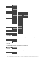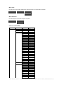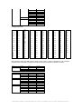
1
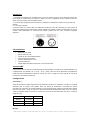
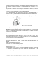
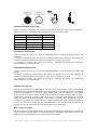
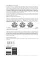
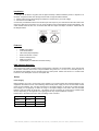
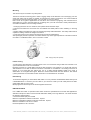
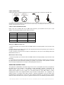
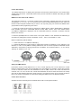
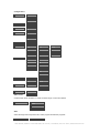
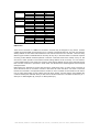
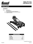
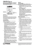
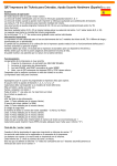
SIRIUS 14 LED 3W RGB 3 IN 1 IP 65
MANUAL DE USUARIO/ USER MANUAL
User Manual | SIRIUS 14 LED 3W RGB 3 IN 1 IP 65 | Triton Blue | Rev.Jan. 2014 | www.triton-blue.com
CASTELLANO
Por su propia seguridad, por favor lea este manual del usuario antes de realizar
la conexión inicial
Toda persona implicada en la instalación, operación y mantenimiento de este aparato tiene que:
-Estar cualificado.
-Considere este manual como parte del producto final.
-Conserve este manual durante toda la vida útil del producto.
-Facilitar el manual a cada sucesivo poseedor o el uso del producto.
-Descarga la última versión del manual en internet en www.triton-blue.com
Introducción
Gracias por haber elegido un Proyector SIRIUS 14 LED 3W RGB 3 IN 1 IP65. Si usted sigue las
instrucciones de este manual, estaremos seguros de que podrá disfrutar de este dispositivo durante un
largo periodo de tiempo.
ANTES DE UTILIZAR
Gracias por adquirir este producto. Cada producto ha sido probado a fondo y ha sido transportado en
perfectas condiciones de funcionamiento. Compruebe cuidadosamente la caja por daños que pueden
haber ocurrido durante el transporte. Si la caja se encuentra dañada, inspecciones con cuidado su
aparato en busca de daños y asegúrese de que todos los accesorios necesarios para funcionar la unidad
han llegado intactos. Desembalar cuidadosamente el cartón, compruebe el contenido y que todas las
partes se han recibido en buenas condiciones.
CORRIENTE ELECTRICA
Este aparato dispone de una fuente de alimentación de conmutación automática que pueden adaptarse a
una amplia gama de tensiones de entrada. Lo único que hay que hacer antes de encender la unidad es
asegúrese de que el voltaje de la línea que está utilizando está dentro del rango de tensiones aceptadas.
Han de estar entre 100V y 240V AC 50-60 Hz. Todos los accesorios deben ser alimentados directamente
y no se puede ejecutar fuera un reóstato (resistencia variable o circuito dimmer, incluso si el reóstato o el
canal de dimmer se utiliza exclusivamente para un 0% a un interruptor de 100%.
Precauciones de seguridad
Por favor, lea estas instrucciones que incluye información importante acerca de la instalación, uso y
mantenimiento de este producto. Por favor, mantenga este manual del usuario para futuras consultas. Si
usted vende la unidad a otro usuario, asegúrese de que ellos también reciben este folleto de
instrucciones. No derrame agua u otros líquidos dentro o sobre la unidad. Asegúrese de que el toma
eléctrica coincide con la de la tensión necesaria para su unidad. No intente poner en funcionamiento esta
unidad si el cable de alimentación está rasgado o roto. No intente quitar ni arrancar la toma de tierra del
cable eléctrico. Esta se utiliza para reducir el riesgo de descarga eléctrica y de fuego en caso de un
cortocircuito. Desconecte del suministro eléctrico antes de realizar cualquier tipo de conexión. No retire la
cubierta bajo ninguna circunstancia. Nunca opere esta unidad cuando se retira la cubierta. Nunca conecte
esta unidad a un regulador de voltaje. Asegúrese siempre de montar esta unidad en una zona que permita
la ventilación adecuada. No intente poner en funcionamiento esta unidad, si se daña. Durante largos
períodos de no utilización, desconecte la alimentación de la unidad. Siempre coloque esta unidad sobre
una superficie segura y estable. Los cables de alimentación deben colocarse de forma que no es probable
que sean pisados o aplastados por elementos colocados sobre o contra ellos.
Limpieza - El dispositivo debe limpiarse sólo como recomiende el fabricante
.Calor - El aparato debe situarse lejos de fuentes de calor tales como radiadores, registros de calor,
estufas u otros aparatos (incluyendo amplificadores) que produzcan calor.
User Manual | SIRIUS 14 LED 3W RGB 3 IN 1 IP 65 | Triton Blue | Rev.Jan. 2014 | www.triton-blue.com
El aparato debe ser reparado por personal de servicio calificado cuando:
A. El cable de alimentación o el enchufe se haya dañado.
B. Han caído objetos o se ha derramado líquido en el aparato.
C. El aparato se haya expuesto a la lluvia o al agua.
D. El aparato no funcione normalmente o muestra un marcado cambio en el rendimiento
No colocar más de10 unidades a 120 V y 20 unidades a 230V.
No hay piezas reparables por el usuario dentro de esta unidad. No intente ninguna reparación, si lo hace,
se anulará la garantía de fábrica.
Vida útil esperada del LED
Los LED´s disminuyen gradualmente su brillo con el tiempo. El calor es el factor dominante que conduce a
la aceleración de esta disminución. Los LED muestran una mayor operatividad a temperaturas que en
condiciones óptimas o ideales. Los LED se utilizan en su máximo de intensidad, la vida de los LED se
reduce significativamente. Se estima que un período de vida viable de 40.000 a 50.000 horas se logrará
en condiciones normales. Si la mejora en esta esperanza de vida es de una prioridad más alta, colocar la
atención en la prestación de temperaturas de funcionamiento más bajas. Esto puede incluir climáticaambiental y la reducción de la intensidad global de proyección
MANUAL DE USUARIO SIRIUS 14 LED 3W RGB 3 IN 1 IP65
Introducción
Este producto se controla mediante 3, 4, 5, 10canales. El aparato puede operar en dos modos; Control
DMX o configurado como Maestro /Esclavo. Este aparato incorpora varios programas que se pueden
utilizar mientras funciona como unidad individual o cuando se utilizan varios aparatos en configuración
Maestro/Esclavo. Para mejores resultados, use niebla o humo de efecto especial para realzar los haces
luminosos.
ADVERTENCIA: Esto puede causar daños graves en los ojos. Evite mirar
directamente a la fuente de luz en todo momento.
Especificaciones
Modelo: SIRIUS 14 LED 3W RGB 3 IN1 IP65
Entrada de alimentación: AC 100-230V, 50-60 Hz
Consumo máximo: 80 watios
Número de canales DMX: 3, 4, 5, 10 canales
Conectores DMX: XLR de 3 pin
Tipo de LED: 3 in 1
Número de LED: 14 LED de 3 watios
Angulo de haz: 25º(opcional 45º)
Protección ambiental: outdoor IP65
Dimensiones: 235x165x300 mm
Peso: 4Kg
Cuerpo: Aluminio
Vida LED: 80.000 horas
NOTA: las especificaciones y mejoras en el diseño de esta unidad y de este manual están sujetas a cambios sin previo aviso escrito.
User Manual | SIRIUS 14 LED 3W RGB 3 IN 1 IP 65 | Triton Blue | Rev.Jan. 2014 | www.triton-blue.com
Instalación
1.- El aparato se puede fijar en cualquier lugar, pero la luz se debe mantener a una distancia mínima de 1
metro desde su salida hasta una persona u objeto. Por favor, asegúrese de que el aparato este bien
fijado, el proyector debe estar conectado a tierra.
2.- Por favor debe asegurarse que la frecuencia y voltaje de su instalación coincida con la que marca el
aparato.
3.- La conexión de DMX:
Conecte el cable con conector XLR a la salida XLR hembra de 3 pin del controlador y el otro extremo al
macho de entrada XLR 3 pin del aparato. Puede multiplicar la cadena. El cable necesario debe ser de dos
núcleos, cable apantallado con conectores de entrada y salida XLR. Por favor, consulte el siguiente
diagrama.
Características
•
•
•
•
•
•
•
Mezcla de color RGB
Efecto strobo de color
Chase de color (velocidad ajustable)
Dimmer electrónico 0-100%
Strobo 0-20hz(cualquier color)
Protocolo DMX 512
Display digital para direccionamiento y funciones de menú
Canales DMX
Este producto tiene un total de 5 configuraciones de canales DMX, conocidas como "Personalidades”. Las
configuraciones son [STAGE, Arc.1, Ar1.D, , Ar1.s, y HSV]. Cada una de las diferentes configuraciones
puede ser seleccionada desde el panel de control. Por favor, consulte la sección "Panel de Control de
Funciones" para realizar la selección.
Configuración
Alimentación
Antes de enchufar la unidad, asegúrese que el voltaje de la fuente en su instalación coincide con el voltaje
requerido para su equipo. Este aparato tiene una fuente de alimentación conmutada de cambio
automático de suministro que pueden adaptarse a una amplia gama de voltajes de entrada. Este aparato
funciona entre 100V y 240V AC 50-60 Hz. Esta luminaria está diseñada para poder unirse en cadena.
Todos los aparatos deben conectarse a circuitos con una toma de tierra adecuada. Por favor, consulte el
código de color.
Cable Conexión Marrón AC Línea Azul AC Neutro Verde/Amarillo AC Tierra Pin 1 2 3 Montaje
User Manual | SIRIUS 14 LED 3W RGB 3 IN 1 IP 65 | Triton Blue | Rev.Jan. 2014 | www.triton-blue.com
Este accesorio se puede montar en cualquier posición segura. El aparato incluye un yugo de montaje.
Usted debe proporcionar su propia pinza y asegúrese de que la pinza es capaz de soportar el peso de
este aparato. Se recomienda usar dos puntos de anclaje. Usted puede utilizar abrazaderas en “O” y en
“C”.
Nota: Hay 2 tipos de aplicaciones para este dispositivo: Soporte de suelo y colgado con los haces hacia
abajo. Son necesarios al menos 1 cable de seguridad / cadena para cada dispositivo, además de la
soportes de montaje.
1. Cuando vaya a colgar el aparato por favor siga los siguientes pasos.
2. Bloquear el acceso al área de trabajo y el uso de la plataforma adecuada.
3. Los Cables de seguridad deben utilizarse siempre, garantizado a través de la seguridad de la
instalación del cable. El cable de seguridad debe ser capaz de sostener 10 veces el peso del aparato.
4. Verificar la estructura puede contener 10 veces el peso de todos los aparatos instalados.
Después de períodos prolongados de funcionamiento, el chasis accesorio puede alcanzar temperaturas
elevadas. Este aparato debe instalarse en un lugar ventilado, ya que es refrigerado por convección.
Nota: La garra es un accesorio opcional
Link De Aparatos
Usted necesitará unir en serie para ejecutar espectáculos de luz de uno o más aparatos usando un cable
DMX-512 desde el controlador para ejecutar espectáculos sincronizados en dos o más aparatos.
Importante: Los aparatos conectados en cadena en una sola línea han de cumplir con la norma EIA-485
no más de 32 dispositivos deben estar conectados. En una serie de más de 32 luminarias puede producir
un deterioro de la señal DMX digital.
Máxima distancia de enlace en serie recomendada: 50 metros (Máximo número recomendado de
aparatos: 32 partidos)
Cableado DMX
Para enlazar los aparatos juntos usted debe obtener los cables de DMX. Usted puede comprar cables
DMX directamente de un concesionario / distribuidor o construir su propio cable. Si opta por crear su
propio cable por favor, utilice cables de tipo de DMX que pueden llevar a una alta calidad de la señal y
son menos propensos a la interferencia electromagnética.
Cable de datos DMX
Utilice un cable equivalente DMX AES, o que cumpla con las especificaciones de la EIA RS-485
Aplicaciones. Cables de micrófono estándar no pueden transmitir datos DMX fiable durante largo
distancias.
El cable tendrá las siguientes características:
2 conductores de par trenzado además de un protector
Capacitancia máxima entre conductores 30 pF / ft.
Capacitancia máxima entre el conductor y el blindaje 55 pF / ft.
La resistencia máxima de 20 ohmios / 1000 ft
Impedancia nominal 120 ohms
La conexión de DMX: Conecte el cable con conector XLR a la salida XLR hembra de 3 pin del controlador
y el otro extremo al macho de entrada XLR 3 pin del aparato. Puede multiplicar la cadena. El cable
necesario debe ser de dos núcleos, cable apantallado con conectores de entrada y salida XLR. Por favor,
consulte el siguiente diagrama.
User Manual | SIRIUS 14 LED 3W RGB 3 IN 1 IP 65 | Triton Blue | Rev.Jan. 2014 | www.triton-blue.com
ESQUEMA CONEXIÓN 3-PIN a 5-PIN
Nota! Si se utiliza un controlador con un conector de salida de DMX de 5 pines, tendrá que utilizar un
adaptador de 5 a 3 pin. El siguiente gráfico detalla la conversión adecuada de cable:
Conductor
3 Pin Hembra (Out)
5 Pin Macho (In)
Ground/Shield
Pin 1
Pin 1
Data (-) signal
Pin 2
Pin 2
Data (+) signal
Pin 3
Pin 3
No usado
No usado
No usado
No usado
CONEXIÓN EN SERIE DE DMX
1. Conecte el lado del conector de 3 pines del cable DMX (macho) a la salida (hembra) de 3 pines del
controlador.
2. Conectar el extremo del cable que viene del controlador que tendrá un conector 3 pin (hembra) al
conector de entrada del DMX IN del aparato que consta de un conector 3 pin (macho).
3. A continuación, proceder a la conexión de la salida de OUTDMX del aparato con el INDMX del
siguiente aparato y a si sucesivamente.
CONEXIÓN MASTER/ESCLAVO
1. Conecte el lado del conector de 3 pines del cable DMX (macho) a la salida (hembra) de 3 pines del
aparato.
2. Conectar el extremo del cable que viene del aparato que tendrá un conector 3 pin (hembra) al
conector de entrada del DMX IN del aparato que consta de un conector 3 pin (macho).
3. A continuación, proceder a la conexión de la salida de OUTDMX del aparato con el INDMX del
siguiente aparato y a si sucesivamente.
Instrucciones de uso
El equipo es direccionable en la gama DMX 001 y 512. En su forma más simple de control, esto permite el
control de hasta 56 aparatos en configuración de11 canales ”STAGE”, sin embargo, existe un "ID" sistema
de dirección secundaria para su uso en un universo limitado DMX y entornos arquitectónicos. El sistema
de dirección de "ID" permite al usuario asignar hasta 66 aparatos en la misma dirección DMX, en efecto,
multiplicando el control de los equipos dentro de un mismo universo de 3.696 aparatos. Se accede al
equipo "ID" sistema de dirección mediante el canal DMX 11 “STAGE”. Esta consideración debe ser
colocada en la programación de las actuaciones en directo o señales que necesitan para desencadenar a
la vista o en una línea de tiempo. Así que, para permanecer en un segundo tiempo de ejecución, el
programa no mayor de 10 luminarias en ID de direccionamiento por canal DMX.
Modo configuración rápida
Para obtener instrucciones detalladas acerca de las operaciones del panel de visualización y funciones de
avance por favor a la sección titulada, "Funciones del panel de visualización". Estos pasos se supone que
usted ha leído y está familiarizado con la creación de un enlace de DMX.
User Manual | SIRIUS 14 LED 3W RGB 3 IN 1 IP 65 | Triton Blue | Rev.Jan. 2014 | www.triton-blue.com
Control DMX-512 y sin dirección "ID"
El equipo funciona en 11 canales de DMX (personalidad "STAGE"). Dirección de cada aparato en
incremento de 10 canales. Para ahorrar tiempo puede utilizar el mismo canal DMX para cada aparato.
Todos los aparatos serán entonces iguales y responderán simultáneamente al control. Así usted puede
agrupar sus instalaciones y atender a los grupos por igual para la programación y un control más rápido.
1. Acceda a la función de panel de control, pulse el botón "MENU" hasta que aparezca el 'MODE RUN'.
Pulse "ENTER" y utilice los botones "UP / DOWN" para seleccionar la función "DMX". A continuación se
muestra, pulse el botón "MENU" hasta que "DIRECCIÓN DMX512 '. Utilice la opción "UP / DOWN"
botones o aumentar o disminuir los canales entre 001 y 512.
2. Pulse el botón (ENTER) para confirmar la acción. A continuación, pulse "MENU" para salir. Desactivar
ID abordar en cada aparato mediante el establecimiento de la función de panel de 'ID ON / OFF' OFF.
"SET" para "ID ON / OFF" en "OFF".
DMX-512 con dirección direccionamiento ID.
Activar ID en cada aparato mediante el establecimiento de la función de panel de "ID ON / OFF" en la
posición ON. "Configuración" para "ID ON / OFF" a "ON" Por cada dirección inicial DMX512 el usuario
puede establecer 66 ID de direcciones separadas. Set.ID direcciones en cada aparato mediante el
establecimiento de la función de panel de "dirección de ID" para valores incrementales. (1,12,24,36 etc ..)
"Configuración" a "dirección" a "01 ~ 66".
Configuración de la dirección DMX
Cada aparato requiere una dirección de inicio 1-512. Un aparato que requiere uno o más canales para el
control comienza a leer los datos en el canal indicado por la dirección de inicio. Por ejemplo, un aparato
que ocupa o utiliza 5 canales de DMX y fue dirigido a iniciar en el canal DMX 100, podría leer los datos de
los canales: 100, 101, 102, 103, y 104. Elija las direcciones de inicio para que los canales utilizados no se
superpongan y tenga en cuenta la dirección de inicio seleccionado para futuras consultas. El equipo utiliza
hasta to11canales de DMX.
Funciones del panel de control
Todas las funciones del aparato y ajustes son accesibles a través de la interfaz del panel de control
incorporado.
Configuraciones
STAT
R (O-255)
G (0-255)
B (0-255)
S (0-255)
AUTO
AT.(1-10)
PR.(1-10)
RUN
DMX
User Manual | SIRIUS 14 LED 3W RGB 3 IN 1 IP 65 | Triton Blue | Rev.Jan. 2014 | www.triton-blue.com
SLA
PERS
STAG
ARC.1
AR1.d
AR1.s
HSv
ID
Id(01-66)
EDIT
PR.01
SC.01
R (O-255)
PR.02
SC.02
G (0-255)
*
*
B (0-255)
*
*
S (0-255)
*
*
T (0-255)
PR.10
SC.30
F (0-255)
UPLd
****
REST
****
ID
ON
SET
OFF
RGB
ON
OFF
DIM
OFF
Dim 1
Dim 2
Dim 3
Dim 4
CAL1
CAL 2
WT01
R (O-255)
*
G (0-255)
WT 11
B (0-255)
RGB
R (O-255)
G (0-255)
B (0-255)
KEY
ON
OFF
Modo Estático
Nos permite seleccionar el color deseado en modo manual, aparte del color también nos deja seleccionar
el strobo
STAT
R (O-255)
G (0-255)
B (0-255)
S (0-255)
Modo Auto
El modo automático nos permite seleccionar internos de reproducción.
AUTO
AT.(1-10)
PR.(1-10)
Modo Run
El modo Run nos permite seleccionar la forma de trabajar entre DMX o Maestro/Esclavo
RUN
DMX
SLA
User Manual | SIRIUS 14 LED 3W RGB 3 IN 1 IP 65 | Triton Blue | Rev.Jan. 2014 | www.triton-blue.com
Modo DMX
El modo DMX nos permite seleccionar el valor de DMX de inicio del aparato
Modo Personalidad
El modo Personalidad nos permite seleccionar el modo de personalidad o modo de funcionamiento de los
canales DMX
PERS
STAG
ARC.1
AR1.d
AR1.s
HSv
Modo ID
El modo ID nos permite seleccionar el valor ID del aparato
ID
Id(01-66)
Modo Edit
El modo Edit nos permite modificar los parámetros de los canales de las programaciones internas
EDIT
PR.01
SC.01
R (O-255)
PR.02
SC.02
G (0-255)
*
*
B (0-255)
*
*
S (0-255)
*
*
T (0-255)
PR.10
SC.30
F (0-255)
Modo Setting
El modo Setting nos permite actualizar el aparato, resetear el aparato activar o desactivar la función ID del
aparato, activar o desactivar el Dimmer y los modos de Dimmer del aparato
SET
UPLd
****
REST
****
ID
ON
OFF
RGB
ON
OFF
DIM
OFF
Dim 1
Dim 2
Dim 3
Dim 4
Modo CAL 1
El modo CAL1 nos permite recalibrar o ajustar a nuestro gusto las distintas funciones de temperaturas de
color modificando los valores de los colores.
CAL1
WT01
R (O-255)
*
G (0-255)
User Manual | SIRIUS 14 LED 3W RGB 3 IN 1 IP 65 | Triton Blue | Rev.Jan. 2014 | www.triton-blue.com
Modo CAL2
El modo CAL2 nos permite modificar las calibraciones de los colores RGB o limitarlas
CAL 2
RGB
R (O-255)
G (0-255)
B (0-255)
Modo KEYLOCK
El modo Keylock nos permite bloquear el aparato
KEY
ON
OFF
Valores de canales DMX
MODE
CHANNEL
VALUE
FUNCTION
STAG
1
0-255
DIMMER
2
0-255
RED
3
0-255
GREEN
4
0-255
BLUE
5
0--10
No Function
11--20
Colour 1
21--30
Colour 2
31--40
Colour 3
41--50
Colour 4
51--60
Colour 5
61--70
Colour 6
71--80
Colour 7
81--90
Colour 8
91--100
Colour 9
101--110
Colour 10
111--120
Colour 11
121--130
Colour 12
131--140
Colour 13
141--150
Colour 14
151--160
Colour 15
161--170
Colour 16
171--180
Colour 17
181--190
Colour 18
191--200
RGB
201--205
White 1
206--210
White 2
211--215
White 3
216--220
White 4
221--225
White 5
226--230
White 6
231--235
White 7
236--240
White 8
241--245
White 9
246--250
White 10
251--255
White 11
0--15
no Strobe
16--255
Strobe
0--9
No Function
10--19
Auto 1
20--29
Auto 2
30--39
Auto 3
40--49
Auto 4
50--59
Auto 5
60--69
Auto 6
70--79
Auto 7
80--89
Auto 8
90--99
Auto 9
100--109
Auto 10
110--119
Pr01
120--129
Pr02
130--139
Pr03
6
7
User Manual | SIRIUS 14 LED 3W RGB 3 IN 1 IP 65 | Triton Blue | Rev.Jan. 2014 | www.triton-blue.com
140--149
Pr04
150--159
Pr05
160-169
Pr06
170-179
Pr07
180-189
Pr08
190-199
Pr09
200--255
Pr10
8
0--255
Speed Auto
9
0--49
Off dimm sp
50--99
Dimm Sp1
100--149
Dimm Sp2
150-199
Dimm Sp3
200--255
Dimm Sp4
Configuraciones ID
0--9
All Ids
10--19
Id 1
20--29
Id 2
30-39
Id 3
40--49
Id 4
50--59
Id 5
60--69
Id 6
70--79
Id 7
80-89
140-149
150-159
160-169
170-179
180-189
190-199
200-209
Id 14
217
Id 28
231
Id 42
245
Id 55
Id 15
218
Id 29
232
Id 43
246
Id 56
Id 16
219
Id 30
233
Id 43
247
Id 57
Id 17
220
Id 31
234
Id 44
248
Id 58
Id 18
221
Id 32
235
Id 45
249
Id 59
Id 19
222
Id 33
236
Id 46
250
Id 60
Id 20
223
Id 34
237
Id 47
251
Id 61
210
Id 21
224
Id 35
238
Id 48
252
Id 62
Id 8
211
Id 22
225
Id 36
239
Id 49
253
Id 63
90-99
Id 9
212
Id 23
226
Id 37
240
Id 50
254
Id 64
100-109
Id 10
213
Id 24
227
Id 38
241
Id 51
255
Id 65
Id 11
214
Id 25
228
Id 39
242
Id 52
256
Id 66
Id 12
215
Id 26
229
Id 40
243
Id 53
Id 13
216
Id 27
230
Id 41
244
Id 54
110-119
120-129
130-139
Notas importantes sobre Stage DMX Operación Dimmer general Canales 1 controla la intensidad del color actualmente
proyectada Cuando el fader está en la posición más alta (255), entonces la intensidad de la salida está en el máximo.
MODE
CHANNEL
VALUE
FUNCTION
HSV
1
0-255
RED
2
0-255
GREEN
3
0-255
BLUE
MODE
CHANNEL
VALUE
FUNCTION
ARC.1
1
0-255
RED
2
0-255
GREEN
3
0-255
BLUE
1
0-255
DIMMER
2
0-255
RED
3
0-255
GREEN
4
0-255
BLUE
1
0-255
DIMMER
2
0-255
RED
3
0-255
GREEN
4
0-255
BLUE
5
0--255
STROBE
AR1.d
AR1.s
User Manual | SIRIUS 14 LED 3W RGB 3 IN 1 IP 65 | Triton Blue | Rev.Jan. 2014 | www.triton-blue.com
DMX Primer
Hay 512 canales en una conexión DMX- 512. Los canales pueden ser asignados de cualquier manera. Un
aparato es capaz de recibir DMX 512, requerirá uno o un número de canales secuenciales. El usuario
debe asignar una dirección de inicio en el aparato que indica el primer canal reservado en el controlador.
Hay muchos tipos diferentes de aparatos DMX controlables y todos ellos pueden variar en el número total
de canales necesarios. La elección de una dirección inicial se debe planificar con antelación. Los canales
no deben solaparse. Si lo hacen, esto se traducirá en un funcionamiento erróneo de los aparatos cuya
dirección inicial se establece incorrectamente. Sin embargo, puede controlar varios aparatos del mismo
tipo con la misma dirección de partida, siempre y cuando el resultado deseado es el de movimiento u
operación unísono, en otras palabras, los aparatos serán esclavizados juntos y todos responden
exactamente igual.
Los aparatos DMX están diseñados para recibir datos a través de una cadena serie. Una conexión en
cadena es donde el OUT de datos de un dispositivo se conecta a los datos de IN del próximo aparato. El
orden en el que están conectados los aparatos no es importante y no tiene ningún efecto sobre cómo un
controlador se comunica a cada aparato. Utilice un orden que prevé el cableado más fácil y directo.
Conectar aparatos usando cables blindados de dos conductores y cable de par trenzado con tres pines
XLR macho a conectores hembra. La conexión de la malla es el pin 1, mientras que el pin 2 es negativo
datos (S -) y el pin 3 es positivo Data (S +)
User Manual | SIRIUS 14 LED 3W RGB 3 IN 1 IP 65 | Triton Blue | Rev.Jan. 2014 | www.triton-blue.com
ENGLISH
For your own safety, please read this user manual carefully before you initially
start-up
Every person involved with the installation, operation and maintenance of this device has to:
-Be qualified.
-Follow the instructions of this manual.
-Consider this manual to be part of the total product.
-Keep this manual for the entire service life of the product
-Pass this manual on to every further owner or use of the product.
-Download the last version of the user manual from the internet in www.triton-blue.com
Introduction
Thank you for having chosen a SIRIUS 14 LED 3W RGB 3 IN 1 IP65Controller. If you follow the
instructions given in this manual, we are sure that you will enjoy this device for a long period of time.
Unpacking
Thank you for purchasing this product. Every product been thoroughly tested and has been transported in
perfect operating condition. Carefully check the carton for damage that may have occurred during
transporting. If the carton appears to be damaged, carefully inspect your fixture for any damage and be
sure all accessories necessary to operate the unit has arrived intact. Carefully unpack the carton, check
the contents to ensure that all parts are present and have been received in good condition.
AC Power
This fixture has an auto-switching power supply that can accommodate a wide range of input voltages.
The only thing necessary to do before powering on the unit is to make sure the line voltage you are
applying is with the range of accepted voltages. This fixture will accommodate between 100V and 230V
AC 50-60Hz. All fixtures must be powered directly off a switched circuit and cannot be run off a rheostat
(variable resistor or dimmer circuit, even if the rheostat or dimmer channel is used solely for a 0% to 100%
switch).
Safety Precautions
Please read these instructions carefully, which includes important information about the installation, usage
and maintenance of this product?
Please keep this User Guide for future consultation. If you sell the unit to another user, be sure that they
also receive this instruction booklet. Do not spill water or other liquids into or on to your unit. Be sure that
the local power outlet matches that of the required voltage for your unit. Do not attempt to operate this unit
if the power cord has been frayed or broken. Do not attempt to remove or break off the ground prong from
the electrical cord. This prong is used to reduce this risk of electrical shock and fire in case of an internal
short. Disconnect from main power before making any type of connection. Do not remove the cover under
any conditions. There are no user serviceable parts inside. Never operate this unit when the cover is
removed. Never plug this unit in to a dimmer pack. Do not attempt to operate this unit, if it becomes
damaged. During long periods of non-use, disconnect the unit´s main power. Always mount this unit in
safe and stable matter. Power-supply cords should be routed so that they are not likely to be walked on or
pinched by items placed upon or against them, paying particular attention to the point they exit from the
unit. Cleaning the appliance fixture should be cleaned only as recommended by the manufacturer.
User Manual | SIRIUS 14 LED 3W RGB 3 IN 1 IP 65 | Triton Blue | Rev.Jan. 2014 | www.triton-blue.com
Heat -The appliance should be situated away from heat sources such as radiators, heat registers, stoves,
or other appliances (including amplifiers) that produce heat.
The fixture should be serviced by qualified service personnel when:
A. The power-supply cord or the plug has been damaged.
B. Objects have fallen, or liquid has been spilled into the appliance.
C. The appliance has been exposed to rain or water.
D. The appliance does not appear to operate normally or exhibits a marked change in performance
To prevent or reduce the risk of electrical shock or fire, do not expose this unit to rain
or moisture. Do not daisy chain power to more than 10 units @ 120V and 20 units @ 230V.
There are no user serviceable parts inside this unit. Do not attempt any repairs
Yourself, doing so will void your manufactures warranty.
LED Expected Lifespan
LEDs gradually decline in brightness over time. HEAT is the dominant factor that leads to the acceleration
of this decline. Packaged in clusters, LEDs exhibit higher operating temperatures than in ideal or singular
optimum conditions. For this reason when all color LEDs are used at their fullest intensity, life of the LEDs
is significantly reduced. lt is estimated that a viable lifespan of 40,000 to 50,000 hours will be achieved
under normal operational conditions. lf improving on this lifespan expectancy is of a higher priority, place
care in providing for lower operational temperatures. This may include climatic-environmental and the
reduction of overall projection intensity.
SIRIUS 14 LED 3W RGB 3 IN 1 IP 65 CONTROLLER USER´S
MANUAL
Introductions
This product is a 3,4,5, or 10 channels. The fixture can operate in three different operating modes; DMX
control, sound-active, or in a Master/Slave configuration. This product comes with several built in programs
that can be used, while operating as a dimmer unit or when used in multiples linked in a Master/Slave
configuration. For best results use fog or special effects smoke to enhance the beams projections.
WARNING: To prevent or reduce the risk of electrical hock or fire, do not expose this unit to rain
or moisture.
WARNING: This may cause severe eye damage. Avoid looking directly into the light source at
all times.
Specifications
Model: SIRIUS 14 LED 3W RGB 3 IN 1 IP 65
Input voltage: AC 100-230V, 50-60 Hz
Max Power: 80 w
DMX control: 3, 4, 5, 10channels
DMX connection: XLR 3 pin
Model LED: 3 in 1
Number LED: 14 LED de 3 watios
Beam angle: 25º(optional 45º)
IP class: outdoor IP65
Packing size: 235x165x300 mm
G.W: 4Kg
Material: Aluminum
Life LED: 80.000 hours
NOTE: Specifications and improvements in the design of this unit and this manual are subject to change without any prior written notice.
User Manual | SIRIUS 14 LED 3W RGB 3 IN 1 IP 65 | Triton Blue | Rev.Jan. 2014 | www.triton-blue.com
Installation
1.- The light can be fixed in any place, but the light must keep a distance between person or objects at 1m
minimum. And please make sure the light is fixed well, the light should be earthed.
2. - Please make sure the rated voltage and frequency should suit to your local voltage.
3. - Connection of the DMX 512:
Connect the provided XLR cable to the female 3-pin XLR output of your controller and the other side to the
male 3-pin XLR input of the light. You can chain multiple moving head together though serial linking. The
cable needed should be two core, screened cable with XLR input and output connectors. Please refer to
the diagram below.
Features
•
•
•
•
•
•
•
RGBW Color Mixing
Color Strobe Effect
LED Chase (Adjust Speeds)
Electronic Dimmer 0-100%
Strobe 0-20hz(all color)
DMX 512 protocol
Digital Display for address and function setting
DMX Channel Summary
This Product has a total of 5 DMX channel configurations, referred to as “Personalities” in this manual and
in the fixture onboard control board. The personalities are [STAG, Arc.1, Ar1.D, Ar1.s, and HSV]. Each of
the different personalities can be accessed from the control panel. Please see section on “Control Panel
Functions” on a description on how to accomplish this.
.Setup
Power Supply
Before plugging your unit in, be sure the source voltage in your area matches the required voltage for your
equipment. This fixture has an auto-switching switch-mode power supply that can accommodate a wide
range of input voltages. The only thing necessary to do before powering on the unit is to make sure the
line voltage you are applying is within the range of accepted voltages. This fixture will accommodate
between 100V and 240V AC 50-60 Hz. . All fixtures must be connected to circuits with a suitable Earth
Ground. Depending on the application, the lighting fixture may require a different connector
Please refer to the below wire color code if installing a new connector.
Wire Brown Blue Green/Yellow Connection AC Live AC Neutral AC Ground Pin 1 2 3 User Manual | SIRIUS 14 LED 3W RGB 3 IN 1 IP 65 | Triton Blue | Rev.Jan. 2014 | www.triton-blue.com
Mounting
This fixture may be mounted in any safe position.
The fixture includes a mounting yoke to which a rigging clamp can be attached. You must supply your own
clamp and make sure the clamp is capable of supporting the weight of this fixture. lt is recommended to
use at least 2 mounting points per fixture. You can order “C” and “O”-clamps.
Note: There are 2 types of applications for this fixture: floor stand for up lighting, and overhead use for
down lighting. lf you are using this fixture for up lighting, then you must use at least 1 safety cable/chain for
each fixture in addition to the mounting brackets..
1. lf hanging the fixture for over head use, then please follow the below steps.
2. Block access below the work area and use suitable and stable platform when installing or servicing
fixture.
3. Safety cables must always be used, secured through safety cable attachment. The safety cable must be
capable of holding 10 times the weight of the fixture.
4. Verify the structure can hold 10 times the weight of all to-be install fixtures.
After prolonged periods of operation, the fixture chassis may reach high temperatures. This fixture must be
mounted in a ventilated location, as it is convection cooled.
Note: Hanging clamp soid separately
Fixture Linking
You will need a serial data link to run light shows of one or more fixtures using a DMX-512 controller to run
synchronized shows on two or more fixtures.
Important: Fixtures on a serial data link must be daisy chained in one single line. To comply with the EIA485 standard no more than 32 devices should be connected on one data link. Connecting more than 32
fixtures on one serial data link without the use of a DMX optically-isolated splitter may result in
deterioration of the digital DMX signal. Maximum recommended serial data link distance: 500 meters
(1640 ft.) Maximum recommended number of fixtures on a serial data link: 32 fixtures
Data Cabling
To link fixtures together you must obtain data cables. You can purchase certified DMX cables directly from
a dealer/distributor or construct your own cable. If you choose to create your own cable please use datagrade cables that can carry a high
Quality signal and are less prone to electromagnetic interference.
DMX DATA CABLE
Use a DMX AES cable or equivalent cable which meets the specifications for EIA RS-485 applications.
Standard microphone cables cannot transmit DMX data reliably over long distances. The cable will have
the following characteristics:
2-conductor twisted pair plus a shield
Maximum capacitance between conductors 30 pF/ft.
Maximum capacitance between conductor and shield 55 pF/ft.
Maximum resistance of 20 ohms / 1000 ft.
Nominal impedance 100 140 ohms
User Manual | SIRIUS 14 LED 3W RGB 3 IN 1 IP 65 | Triton Blue | Rev.Jan. 2014 | www.triton-blue.com
CABLE CONNECTORS
Cabling must have a male XLR connector on one end and a female XLR connector on the other end.
CAUTION Do not allow contact between the common and the fixture’s chassis ground. Grounding the common can cause a ground loop,
and your fixture may perform erratically. Test cables with an ohm meter to verify correct polarity and to make sure the pins are not
grounded or shorted to the shield or each other.
3-PIN TO 5-PIN CONVERSION CHART
Note! If you use a controller with a 5 pin DMX output connector, you will need to use a 5 pin to 3 pin
adapter. The chart below details a proper cable conversion::
Conductor
3 Pin Female (Out)
5 Pin Male (In)
Ground/Shield
Pin 1
Pin 1
Data (-) signal
Pin 2
Pin 2
Data (+) signal
Pin 3
Pin 3
Do not use
do not use
Do not use
do not use
Setting up a DMX Serial Data Link
1. Connect the (male) 3 pin connector side of the DMX cable to the output (female) 3 pin connector of the
controller.
2. Connect the end of the cable coming from the controller which will have a (female) 3 pin connector to
the input connector of the connector.
3. Then, proceed to connect from the output as stated above to the input of the following DMX OUT
DMX IN fixture and so on.
Master/Slave Fixture Linking
1. Connect the (male) 3 pin connector side of the DMX cable to the output (female) 3 pin connector of the
first fixture.
2. Connect the end of the cable coming from the first fixture which will have a (female) 3 pin connector to
the input connector of the next fixture consisting of a (male) 3 pin connector. Then, proceed to connect
from the output as stated above to the input of the following fixture and so on.
OPERATING INSTRUCTIONS
The equipment is addressable in the DMX range of 001 to 512. ln its simplest control form, this allows for
the control of up to 56 fixtures in the11-channel “STAG” personality; however, a secondary “ID”
address system exists for use in a limited DMX universe and architectural environments. The “ID”
address system allows the user to assign up to 66 fixtures within the same DMX address; in effect,
multiplying the control of the equipment within a single universe to 3,696 fixtures. The equipment “ID”
address system is accessed using DMX channel 11 [STAG]. Consideration must be placed when
programming live performances or cues that need to trigger on demand or on a time line. So, to remain
within one second execution time, program no greater than 10 fixtures on ID addressing per DMX channel.
User Manual | SIRIUS 14 LED 3W RGB 3 IN 1 IP 65 | Triton Blue | Rev.Jan. 2014 | www.triton-blue.com
Control Quick Setup
For detailed instructions on display panel operations and functions please advance to the section titled;
“Display Panel Functions”. These steps assume that you have read and are familiar with setting up a DMX
serial data link.
DMX-512 control without “ID” address
The equipment operates on 11 channels of DMX (“STAG” personality). Address each fixture in increments
of10channels. (1, 11, 21, 31, etc...) To save time you can use the same DMX address for each fixture. All
fixtures will then respond simultaneously to control. You may also group your fixtures and address those
groups alike for faster programming and control.
1. Access the control panel function by pressing the “MENU” button until the ‘RUN MODE’ is displayed.
Press “ENTER” and use the “UP/DOWN” buttons to select ‘DMX’ function. Then, Press “MENU” button
until ‘DMX512 ADDRESS’ is displayed. Use the “UP/DOWN” buttons to increase or decrease channels
between 001 and 512.
2. Press the (ENTER) button to confirm action. Then press “MENU” to exit. Deactivate ID addressing in
each fixture by setting panel function ‘ID ON/OFF’ to OFF. “SET” to “ID ON/OFF” to “OFF”.
DMX-512 addressing with ID address
1. Follow instructions 1 for DMX512 addressing.
2. Activate ID addressing in each fixture by setting panel function “ID ON/OFF” to ON. “Settings” to “ID
ON/OFF” to “ON” For every DMX512 starting address the user can set 66 separate ID addresses. Set.ID
addresses in each fixture by setting panel function “ID address” to incremental values. (1, 12, 24, 36 etc.)
“Settings” to “address” to “01 ~ 66”
Setting the DMX address
Each fixture requires a start address from 1 to 512. A fixture requiring one or more channels for control
begins to read the data on the channel indicated by the start address. For example, a fixture that occupies
or uses 5 channels of DMX and was addressed to start on DMX channel 100, would read data from
channels: 100, 101, 102, 103 and 105. Choose start addresses so that the channels used do not overlap
and note the start address selected for future reference. The equipment uses up to11channels of DMX. lf
this is your first time using DMX, we recommend reading the DMX Primer in the Appendix Section.
Control Panel Functions
All fixture functions and settings are accessible via the built-in control panel interface.
User Manual | SIRIUS 14 LED 3W RGB 3 IN 1 IP 65 | Triton Blue | Rev.Jan. 2014 | www.triton-blue.com
Configurations
STAT
R (O-255)
G (0-255)
B (0-255)
S (0-255)
AUTO
AT.(1-10)
PR.(1-10)
RUN
DMX
SLA
PERS
STAG
ARC.1
AR1.d
AR1.s
HSv
ID
Id(01-66)
EDIT
PR.01
SC.01
R (O-255)
PR.02
SC.02
G (0-255)
*
*
B (0-255)
*
*
S (0-255)
*
*
T (0-255)
PR.10
SC.30
F (0-255)
UPLd
****
REST
****
ID
ON
SET
OFF
RGB
ON
OFF
DIM
OFF
Dim 1
Dim 2
Dim 3
Dim 4
CAL1
CAL 2
WT01
R (O-255)
*
G (0-255)
WT 11
B (0-255)
RGB
R (O-255)
G (0-255)
B (0-255)
KEY
ON
OFF
Static Colour
Combine Red, Green and Blue to create an infinite range of colors and Stobes
STAT
R (O-255)
G (0-255)
B (0-255)
S (0-255)
Auto
Select the target Auto and press Enter, select program and edit the programs.
AUTO
AT.(1-10)
User Manual | SIRIUS 14 LED 3W RGB 3 IN 1 IP 65 | Triton Blue | Rev.Jan. 2014 | www.triton-blue.com
PR.(1-10)
Run
Enter the Run mode to set working mode DMX or Slave
RUN
DMX
SLA
DMX
Enter the DMX mode to set the DMX Address
Personality
Enter the Personality mode to set DMX mode STAGE, ARC 1, Ar1d, Ar1s or Hsv
PERS
STAG
ARC.1
AR1.d
AR1.s
HSv
ID
Enter the ID mode to set the ID Address
ID
Id(01-66)
Edit
Enter the EDIT mode to edit the custom programs
EDIT
PR.01
SC.01
R (O-255)
PR.02
SC.02
G (0-255)
*
*
B (0-255)
*
*
S (0-255)
*
*
T (0
-255)
PR.10
SC.30
F (0-255)
Setting
Enter the SET mode to select and modify the parameters of the fixture or configurations
SET
UPLd
****
REST
****
ID
ON
OFF
RGB
ON
OFF
DIM
OFF
Dim 1
Dim 2
Dim 3
Dim 4
User Manual | SIRIUS 14 LED 3W RGB 3 IN 1 IP 65 | Triton Blue | Rev.Jan. 2014 | www.triton-blue.com
CAL 1
The CAL1 mode allows us to recalibrate or adjust to our taste the different functions of color temperatures
by changing color values.
CAL1
WT01
R (O-255)
*
G (0-255)
WT 11
B (0-255)
CAL2
The CAL2 mode allows us to modify the calibrations of the RGB colors or limit
CAL 2
RGB
R (O-255)
G (0-255)
B (0-255)
KEYLOCK
The Keylock mode lets you lock the device
KEY
ON
OFF
DMX 512 Channel Values
MODE
CHANNEL
VALUE
FUNCTION
STAG
1
0-255
DIMMER
2
0-255
RED
3
0-255
GREEN
4
0-255
BLUE
5
0--10
No Function
11--20
Colour 1
21--30
Colour 2
31--40
Colour 3
41--50
Colour 4
51--60
Colour 5
61--70
Colour 6
71--80
Colour 7
81--90
Colour 8
91--100
Colour 9
101--110
Colour 10
111--120
Colour 11
121--130
Colour 12
131--140
Colour 13
141--150
Colour 14
151--160
Colour 15
161--170
Colour 16
171--180
Colour 17
181--190
Colour 18
191--200
RGB
201--205
White 1
206--210
White 2
211--215
White 3
216--220
White 4
221--225
White 5
226--230
White 6
231--235
White 7
236--240
White 8
241--245
White 9
246--250
White 10
251--255
White 11
0--15
no Strobe
16--255
Strobe
0--9
No Function
10--19
Auto 1
20--29
Auto 2
30--39
Auto 3
6
7
User Manual | SIRIUS 14 LED 3W RGB 3 IN 1 IP 65 | Triton Blue | Rev.Jan. 2014 | www.triton-blue.com
40--49
Auto 4
50--59
Auto 5
60--69
Auto 6
70--79
Auto 7
80--89
Auto 8
90--99
Auto 9
100--109
Auto 10
110--119
Pr01
120--129
Pr02
130--139
Pr03
140--149
Pr04
150--159
Pr05
160-169
Pr06
170-179
Pr07
180-189
Pr08
190-199
Pr09
200--255
Pr10
8
0--255
Speed Auto
9
0--49
Off dimm sp
50--99
Dimm Sp1
100--149
Dimm Sp2
150-199
Dimm Sp3
200--255
Dimm Sp4
ID Mode
0--9
All Ids
10--19
Id 1
20--29
Id 2
30-39
Id 3
40--49
Id 4
50--59
Id 5
60--69
Id 6
70--79
Id 7
80-89
140-149
150-159
160-169
170-179
180-189
190-199
200-209
Id 14
217
Id 28
231
Id 42
245
Id 55
Id 15
218
Id 29
232
Id 43
246
Id 56
Id 16
219
Id 30
233
Id 43
247
Id 57
Id 17
220
Id 31
234
Id 44
248
Id 58
Id 18
221
Id 32
235
Id 45
249
Id 59
Id 19
222
Id 33
236
Id 46
250
Id 60
Id 20
223
Id 34
237
Id 47
251
Id 61
210
Id 21
224
Id 35
238
Id 48
252
Id 62
Id 8
211
Id 22
225
Id 36
239
Id 49
253
Id 63
90-99
Id 9
212
Id 23
226
Id 37
240
Id 50
254
Id 64
100-109
Id 10
213
Id 24
227
Id 38
241
Id 51
255
Id 65
Id 11
214
Id 25
228
Id 39
242
Id 52
256
Id 66
Id 12
215
Id 26
229
Id 40
243
Id 53
Id 13
216
Id 27
230
Id 41
244
Id 54
110-119
120-129
130-139
Important Notes on Operation DMX Stage dimmer overall Channel 1 controls the intensity of the color currently projected
When the slider is in the highest position (255), then the intensity output is at the maximum.
User Manual | SIRIUS 14 LED 3W RGB 3 IN 1 IP 65 | Triton Blue | Rev.Jan. 2014 | www.triton-blue.com
MODE
CHANNEL
VALUE
FUNCTION
HSV
1
0-255
RED
2
0-255
GREEN
3
0-255
BLUE
MODE
CHANNEL
VALUE
FUNCTION
ARC.1
1
0-255
RED
2
0-255
GREEN
3
0-255
BLUE
1
0-255
DIMMER
2
0-255
RED
3
0-255
GREEN
4
0-255
BLUE
1
0-255
DIMMER
2
0-255
RED
3
0-255
GREEN
4
0-255
BLUE
5
0--255
STROBE
AR1.d
AR1.s
DMX Primer
There are 512 channels in a DMX-512 connection. Channels may be assigned in any manner. A fixture
capable of receiving DMX 512 will require one or a number of sequential channels. The user must assign a
starting address on the fixture that indicates the first channel reserved in the controller. There are many
different types of DMX controllable fixtures and they all may vary in the total number of channels required.
Choosing a start address should be planned in advance. Channels should never overlap. if they do, this
will result in erratic operation of the fixtures whose starting address is set incorrectly. You can however,
control multiple fixtures of the same type using the same starting address as long as the intended result is
that of unison movement or operation, in other words, the fixtures will be slaved together and all respond
exactly the same.
DMX fixtures are designed to receive data through a serial Daisy Chain. A Daisy Chain connection is
where the DATA OUT of one fixture connects to the DATA IN of the next fixture. The order in which the
fixtures are connected is not important and has no effect on how a controller communicates to each fixture.
Use an order that provides for the easiest and most direct cabling. Connect fixtures using shielded two
conductor twisted pair cable with three pin XLR male to female connectors. The shield connection is pin 1,
while pin 2 is Data Negative (S-) and pin 3 is Data positive (S+).
User Manual | SIRIUS 14 LED 3W RGB 3 IN 1 IP 65 | Triton Blue | Rev.Jan. 2014 | www.triton-blue.com