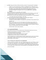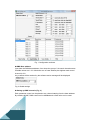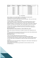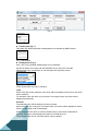
1
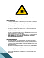
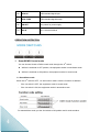
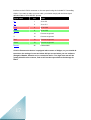
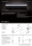
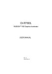
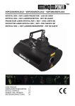
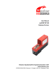
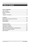
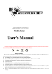
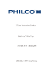
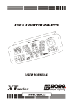
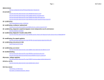
User Manual
Hadfield Management Ltd
Please read this manual carefully before you initially start-up!
OPEN THE BOX FOR CHECKING
Thank you for choosing of this product Club Scene Tri-color Laser show System.
In order to use this product safety and reasonable, please read over this manual carefully
before use and the operation must strictly according to this manual to avoid any damage
to the product and personal safety.
Once you receive this product, please immediately take it out carefully and check whether
the product was damaged during the transportation. Then please check if the following
parts are included:
Club Scene laser projector
Power cable
DMX signal cable
User manual
1pc
1pc
1pc
1pc
Specifications
Laser type:
Green Laser: Diode Pumped Solid Stated Laser (DPSSL)
Red Laser: Semiconductor Diode Laser
Laser class:
Class IV
Laser life:
>5000 Hours
Cooling ways:
Air-cooled.
Color:
Red @650nm
Green@532nm
Laser output:
180mW (120mW@650nm 60mW@532nm)
Scanner system:
20Kpps optical scanner
Optical angle:
0~±20°
Control mode:
Sound active/Auto mode with simultaneous operation
USITT DMX512 (10channels)
Playback of ILDA lasershow files in SD card(6channels)
ILDA 25-pin Interface for PC controller
Power supply:
AC 110-240V 50/60Hz
Power consumption: <300W
Dimensions:
W200mm ×H260 mm ×D450 mm
Net Weight:
6.0Kg
1
DANGER LASER RADIATION!
Avoid direct eye exposure!
Laser radiation can cause eye damage and/or skin damage
All protective measures for a safe operation of this laser must be applied.
Safety instructions
-
-
-
If the device has been exposed to drastic temperature fluctuation, do not switch it on
immediately. The arising condensation water might damage your device. Leave the
device switched off until it has reached room temperature.
The laser must only be used for shows. The operation is only allowed if it is controlled
by a skilled and well-trained operator.
Never leave this device running unattended and keep it away from children and amateurs.
Keep away from heaters and other heating sources. In order to safeguard sufficient
ventilation, leave 50 cm of free space around the device.
Never direct the laser beam to people or animals.
CAUTION LASER DIODE: Never unscrew the housing!
There are no serviceable parts inside the device. Maintenance and service operations
are only to be carried out by authorized dealers.
Always disconnect from the mains when the device is not in use or before cleaning it.
HEALT HAZARD! Never look directly into the light source, as sensitive
persons may suffer an epileptic shock!
Operating determinations
-
-
2
The operator has to make sure that laser radiation – also reflected laser radiation –
higher than the highest allowed level is avoided by technical or organizational measures.
Make sure that the used voltage is: AC 110V~240V, 50/60Hz with ground.
If the device is used in a flying installation, the mounting brackets and an appropriate
safety-rope must be fixed.
Laser effects are not designed for permanent operation. Consistent operation breaks
will ensure that the device will serve you for a long time without defects.
In some country, the operator must notify the accidence insurance and the authority
for industrial safety, before operating a laser. For more information, contact the
relevant authorities.
Please consider that unauthorized modifications on the device are forbidden due to
safety reasons!
-
If this device will be operated in any way different to the one described in this manual,
the product may suffer damages and the guarantee becomes void.
Furthermore, any other operation may lead to dangers like short-circuit, burns, electric
shock,
Product Rear View
FUNCTION TABLE:
1
MIC
Audio in
2
VOLUME
Volume sensitive
4
Message center
Indicating the state of SD card controlling system
3
SD Card Controlling
Settings
Used to set some important parameters for SD card
5
SD Card
SD Card (maximum capacity of 1 Gigabytes support)
6
Mode Switch
Select the operating modes
7
DMX IN
DMX 512 signal input
8
DMX OUT
DMX 512 signal output
9
START ADDRESS
Setting the DMX start address
3
10
ILDA IN
ILDA standard signal input
11
ILDA THRU
ILDA standard signal through
12
ON/OFF
Key switch for power supply
13
AC IN
AC 110-240V 50/60Hz
OPERATION INSTRUTION
1. Sound&DMX Control mode
You can choose Sound or DMX control mode through the 10th switch:
While it is switched to OFF position, the equipment works in sound/auto mode.
While it is switched to ON position, the equipment works in sound mode.
1.1 Sound/Auto mode
When the 10th switch is OFF, 1-9 are function codes. Here the functions as bellows:
-
If the 1st switch is OFF, the equipment works in sound mode.
-
If the 1st switch is ON, the equipment works in automatic mode.
For master/slave mode, put the 2nd switch to ON position and it works as slave.
4
1.2 DMX Control mode
For DMX mode, the 10th dip switch must be ON. Then, set the DMX base address with
the binary system “0” or “1” through switch 1-9
Examples:
DMX
address
DMX
address
1
33
65
113
161
225
DMX base adds. 1-10 setting: (ON is 1, OFF is 0)
1
~
10
Function
0,0,0,0,0,0,0,0,0,0
Sound Control
1,0,0,0,0,0,0,0,0,0
0,1,0,0,0,0,0,0,0,0
Auto Mode
Auto
1,1,0,0,0,0,0,0,0,0
Number from rear
x,x,x,x,x,x,x,x,x,1
DMX 512 control
5
The device has 10 operating channels. If you set the first on DMX address “1”, the next
DMX device can follow at address 20.
DMX channels assignment:
Channel
1.Control Mode
2.Blanking
& Blackout
F
I
R
S
T
3.Pattern
4.Vertical Move
P
A
T
T
E
R
N
5.Horizontal
Move
6.Vertical Roll
7.Horizontal Roll
G
R
O
U
P
8.Rotation
9.Zoom In
& Out
10.Point Draw
6
DMX512
VALUE
FUNCTION
0--63
Sound control (3-10ch useless)
64--127
Auto mode (3-10ch useless)
128--191
DMX control
192--255
Auto mode
0--5
blackout
6--15
red
16--25
green
26--35
yellow
36--105
single color(auto)
106--175
tri-color(auto)
176--245
tri-color(move)
246--255
bounded color
0--255
124patterns(0-255)
0--127
manual vertical move
128--191
auto down, speed up accordingly
192--255
auto up, speed up accordingly
0-127
manual horizontal
128--191
manual right, speed up accordingly
192-255
manual left, speed up accordingly
0--127
manual vertical rotation
128--255
auto vertical rotation, speed up accordingly
0--127
manual horizontal rotation
128--255
auto horizontal rotation
0--127
manual rotation
128--191
auto clockwise rotation, speed up accordingly
192--255
auto anti-clockwise rotation, speed up
accordingly
0--85
from small to large, speed up accordingly
86--170
from large to small, speed up accordingly
171--255
large ←→ small, speed up accordingly
0--255
0--nil
1~255—faint ~bright
2. SD Card Controlling Mode
2.1 SD CARD Controlling Settings Panel
The panel can be used to access some important parameters for the ILDA projector.
If the memory of the panel is empty, it displays “Err” at power-on.
At normal function, if parameters are set correctly, the panel displays the actual DMX
base address, for example “001”.
There are 3 keys from left to right:
1. FUNC
By pressing FUNC, the actual parameter for changing is selected.
There are 2 parameters currently available:
“Adr” = DMX base address
“Ort” = orientation of the projection
2. SEL
After selected the parameter with FUNC, press SEL and the current stored value will be
displayed.
By pressing SEL again, the digit for changing will blink.
Pressing Select multiple times will activate all digits by blinking one after the other.
3. Up
Use this key to change the current number in the blinking digit. The number will be
increased.
When reaching the maximum number (9), the number will be start from zero again.
Example:
Set DMX base address to 200.
Press “FUNC” until “Adr” blinks
Press “SEL” until current value is displayed and right digit blinks
Press “Up” until “0” is reached.
Press “SEL” to go to middle digit
Press “Up” until “0”.
Press “SEL” until left digit blinks
Press “Up” until “2” is reached.
Press “FUNC” for exit this parameter. The value is stored automatically.
All values are stored and activated when exit the parameter input by pressing “FUNC
parameter. The value is stored automatically.
After not changing anything in the parameter input routine, the panel will return to main
routine after about 10 seconds without storing value to memory.
Note that playback of longer shows may be interrupted (stopped) when changing
parameters at the panel during show output. Display of single frames of short
7
sequences normally will not be interrupted.
Limits
DMX base address 1 – 512
Intensity 0 – 99
Orientation 0 – 7
Limits will be controlled automatically by the panel. If trying to set a value beyond the limits,
the panel automatically corrects to an allowed value during input.
Intensity
For the projector, this value should be set to 99.
Orientation
There are 8 different values possible, allowing all possible projection orientations.
This is important for back projections or if it is not clear how the projector is installed at
the location.
0: normal
1: X invert
2: Y invert
3: X and Y invert
4: X and Y changed
5: X and Y changed and X invert
6: X and Y changed and Y invert
7: X and Y changed and both inverted
2.2 Message center
If any error condition occurs, a code will be displayed on the status-LEDs (see table).
Not all errors will cause a stop of playback.
Errors from the memory card (read/write) will cause a total shutdown of the player.
If there is no card or the card is not inserted correctly of if there is no right format or file
system, the player functions will be shut down.
When there is no file allocated to a selected show number, this is no error condition and
the player
will switch the output to Pause (Shown umber 0 PAUSE).
When the accessed show file is not valid or corrupted, the playback will be switched off.
All other functions keep running and the selection of another show is possible.
Ready
DMX
Data
Error
===========================
Yellow
No MMC/SD-card
Yellow
Red
File system FAT16 not found
Yellow
Yellow
Red
Data error when reading MMC/SD-card
Yellow
Yellow
File not found or invalid file
Yellow
x
No DMX-signal
Yellow
Green
Ready
8
2.3 DMX channels assignmet
Channel1: Show select L
This channel is used for show selection; one of the first 16 shows (including Pause) can
be selected.
Channel2: Show select H
16 banks of shows, 16 shows each, 256 shows can be selected using this function.
Channel3: Size (projection size)
When you change size by the use of DMX-control, a fader position of 0 (minimum) can
cause a standing laser beam. This can be a dangerous condition!
DMX only allows a refresh rate of 50 Hz.
Moving a control fader fast will result in jumps of the display settings.
Channel4: Offset X (horizontal position)
A value of zero results in the maximum negative offset.
128 is the center position and 255 is the maximum positive offset.
When changing this value via DMX, the projected display can jump, because DMX
signal rate is slow.
Channel5: Offset Y (vertical position)
See Offset X.
Channel6: Frame repeat
Shows in ILDA-format do not contain any timing information. When all frames of a show
are outputted one after the other, the animation speed is too fast.
By repeating every frame a number of times, the speed of the animation movement can
be controlled. Values by DMX-control are 1 to 16.
2.4 Memory card (Compact Flash card)
All Compact Flash cards up to a maximum capacity of 2 Gigabytes (!) can be used.
2.4.1 Important
The card has to be formatted with FAT16 file system only.
The manufacturer recommends the use of high quality cards.
No-name cards can cause read errors.
All cards shipped together with the equipment are formatted correctly and must NOT
be reformatted.
2.4.2 Caution
9
When using own cards or reformat cards by using a PC with Windows** operating
system, it is not ensured, that the cards are formatted FAT16. Depending on the
memory size of the card, Windows** can format these to FAT12, FAT16 or FAT32
file system. The Poseidon will not work with other file systems than FAT16.
Avoid formatting the card by the use of a PC with Windows** operating
system!
No subdirectories are supported by the Poseidon!
All show files and configuration files must be placed in the root directory of the card.
Subdirectories are allowed, but cannot be found by the Poseidon-system.
There may be not more than 260 files located in the root directory. It is recommended
not to store more files as necessary on the card.
Only short filenames will be processed (8.3-format) by the Poseidon!
The Poseidon does not support long filenames.
The name of the files should be not longer than 8 characters plus the extension (for
example ILD).
When copying files to the card, both long and short filenames are created. The
Poseidon only reads the short names. The long names need additional space in
the root directory. To avoid losing space (and limiting maximum possible number of
files), the names should be kept as short as possible.
Short filenames are not case sensitive!
2.4.3 Reserved Filenames
Some filenames are reserved for device control. These files will be read out by the
Poseidon automatically and must NOT be deleted or renamed.
The following filenames are reserved:
CONFIG.DAT Contains output settings for the Poseidon.
FLASHMP.BIN Controls program for firmware update.
FWUP12C.BIN File for a specific firmware update. When this file is found, the Poseidon
automatically updates the firmware. After this procedure, this file will be deleted
automatically by the Poseidon.
2.4.4 Creating the Configuration file CONFIG.DAT
The free software tool inside the SD card, shipped together with every Poseidon, allows
the creation and modification of the configuration file. DMX-base address can be set
and every control parameter can be directed to a specific DMX-channel inside the group
of 16 channels. Also, DMX-control of every parameter can be disabled and a fixed value
can be set instead.
10
Fig. 1 Configuration software
DMX-Base address
Input here the DMX-base address, from where the group of 16 control channels starts.
Possible values are 1-512. Maximum sum of base address plus highest used control
channel is 512.
Any overflow will be watched by the software and a message will be displayed.
Fig. 2 Global settings
Setting up DMX-channels (Fig. 3)
Each parameter control can be placed to any channel starting from the base address.
By checking NONE, DMX-control can be disabled and a fixed value can be used.
11
Fig. 3 DMX-channel selection
Showselect L
This DMX-function cannot be disabled!
Input here the channel for show selection.
When just this channel is used for show selection, one of the first 16 shows (including
Pause) can be selected.
Showselect H
Input the channel number corresponding to this function here.
16 banks of shows, 16 shows each, can be selected using this function.
When DMX-control of this function is disabled, only shows number 0 (pause) to 15 are
selectable from the control desk.
Speed Kpps
Input the channel number corresponding to this function here.
This function controls the output speed (points per second).
The POSEIDON can output a maximum speed of 30000 points per second and 1000
points per second minimum.
Keep in mind that changing the point output speed also will change the speed of the
displayed animation and also will influence the blanking settings (blank shifting). For this
reason, the speed should be adjusted carefully.
When DMX-control of this function is disabled, the value set in the showtable individual
for every show is used.
Framerepeat
Input the channel number corresponding to this function here.
Shows in ILDA-format do not contain any timing information. When all frames of a show
are outputted one after the other, the animation speed is too fast.
By repeating every frame a number of times, the speed of the animation movement can
be controlled. Common used values are 3-6. Values by DMX-control are 1 to 16.
When DMX-control of this function is disabled, the value set in the showtable individual
for every show is used.
Size (projection size)
12
Input the channel number corresponding to this function here.
When you change size by the use of DMX-control, a fader position of 0 (minimum) can
cause a standing laser beam. This can be a dangerous condition!
It is recommended not to use this DMX-control and use the fixed global value instead,
or to use laser projectors with a scanner safety circuit only.
This ensures the laser emission being shut down during dangerous conditions.
Also the scanners can be overloaded when increasing the scan angle at the same scan
speed.
DMX only allows a refresh rate of 50 Hz.
Moving a control fader fast will result in jumps of the display settings.
Offset X (horizontal position)
Input the channel number corresponding to this function here.
This setting has an unsigned value. A value of zero results in the maximum negative
offset.
128 is the center position and 255 is the maximum positive offset.
When changing this value via DMX, the projected display can jump, because DMX
signal rate is slow.
When DMX-control of this function is disabled, the value set behind „global Value“ will
be taken.
For center position, use a value of 128!
Offset Y (vertical position)
See Offset X.
Blankshift
Input the channel number corresponding to this function here.
This function can be controlled in 16 steps.
Here, the timing of the blanking (Laser = off) and the colors can be controlled.
Because the scanners are slower than the changes of colors or blanking, these changes
have to be delayed. Common used values are 2 to 5. Possible values are 0 to 15.
When DMX-control of this function is disabled, the value set behind “global Value” will
be taken.
A global value for all shows often is critical, because different shows need different
settings.
The best solution is to adjust the value via DMX and save the settings together with the
show selection as a scene on the DMX-desk.
Note: Changing the point speed (Kpps) will also make it necessary to change
blankshifting.
The Showtable (Fig. 4)
In the showtable, all DMX-values of the channels ShowselectH and ShowselectL are
listed, giving a maximum count of 256 shows plus 2 separate shows for Trigger inputs.
A show file and several show parameters can be allocated to every DMX-value.
When only using ShowselectL for showselection, rows from 16 to 255 don't care,
because only 15 shows plus Pause can be accessed by DMX-control.
13
Fig. 4 Showtable
When clicking in a row under Filename, a dialog opens for selecting a file.
The same file can be used in different rows of the table.
Watch that the card (removable media) is selected as the path. Then you can be sure,
that your show file is available on the card.
It is also possible to work in a backup directory on the hard disk and then copy the
whole content to the memory card. But then, it must be sure, that there are short
filenames available. This is normally only sure, when using FAT-file system. Otherwise,
Windows** will create a short filename, when copying data to memory card, and the
names would be changed. The player then will not find the filename on the card.
It is better, first to place all show files on the memory card and then selecting them
directly from the card!
Note for Windows** 2000 or Windows** XP with NTFS-file system:
NTFS will not create short filenames or change the names when copying files to the
card.
It is recommended first copying all show files to the card and then select all files directly
from the memory card, when making configuration.
Speed Kpps (Fig. 6)
This is the output speed (point rate) for the current show.
This value only will be used, when the speed is not controlled by DMX-channel.
The lasershow player supports a maximum output speed of 30 Kpps (30000 points per
second). When using a value greater than 30000, the player limits the speed to 30K
internally.
When clicking into the field Speed Kpps, a dialog opens, where speed, framerepeat and
displaymode can be selected.
Copy and paste can be used to copy all values of a row into another row of the
showtable (Fig. 5).
14
Fig. 5
Fig. 6 Speed pps
Framerepeat (Fig. 7)
This value only will be used when framerepeat is not controlled by DMX-channel.
Fig. 7 framerepeat
Displaymode (Fig. 8)
Here, one of four possible displaymodes can be selected.
PAUSE is fixed to one mode and the TRIGGER shows only offer 2 modes.
Displaymode is the combination of 2 showmodes and 2 priority modes.
Fig. 8
The 2 showmodes are Loop or Oneshot.
Loop
When using this mode, playback of the show will be repeated as long as no new show
will be selected.
For example, when the show only consists of one single frame, this frame will be
displayed permanently.
Oneshot
The selected show will be displayed exactly one time.
When the show only consists of one single frame, this frame will be displayed n-times,
where n is the value under Framerepeat.
When playback of the show or frame is finished and no new show is selected for
playback, the player automatically will switch to PAUSE (show 0).
The 2 showmodes can be combined with 2 output priorities.
15
These are Complete and Interruptable.
Complete
The current running show will be outputted completely, before any new showselection is
possible.
Interruptable
The current running show will be aborted, when a new show is selected.
The following combinations are possible:
Loop/Complete
The current show always is displayed completely and will restart from the beginning,
when no new showselction is recognized at the end of the show.
Loop/Interruptable
The current show will be repeated, when no new show is selected. When selecting a
new show, the current running show will be aborted.
Oneshot/Complete
The show will be displayed completely, exactly one time
Oneshot/Interruptable
The show will be displayed exactly one time, but will be aborted when a new show is
selected.
Exceptions
Show number 0 (Pause) is always Loop/Interruptable.
Triggershows will be displayed only one time (Oneshot), because these shows will be
selected edge triggered.
Note
When a show is running in Complete-mode, all parameters like speed, size, offset,
framerepeat and blankshift will be held (also when controlled by DMX).
Otherwise, the parameters would be changed when selecting a new show during
playback of the current show.
The Pauseshow
Normally, the filename at show number 0 (Pause) is left blank.
When selecting Pause or after finishing playback, the laser is blanked and the output is
stopped.
In some special cases, for example when using the system as an advertising display
without DMX, it could be necessary to playback a show without any additional control.
When placing a show file to show number 0 (pause), this show always will be outputted,
when no other show is selected.
Useful combinations of display modes
Long shows should be interruptable to allow changing to another show.
Short shows or short effects should be set to Complete.
Single frames should be set to Loop, because otherwise they just will be displayed parts
of a second.
Special sequences as a highlight of a show should be set to Oneshot.
3. PC MODE
Put the mode switches to PC MODE position and then connect the PC ILDA output
16
interface to the ILDA IN connector on the rear panel using the included PC Controlling
Cable. If you want to make your own cable, you should comply with the blow signal
definition table of ILDA-DB-25F pinouts.
Signal name
Pin
Notes
X+
1
-5 to +5V
Y+
2
-5 to +5 V
Red+
5
0V to 2.5V
Green+
6
0V to 2.5V
X-
14
Connect to ground
Y-
15
Connect to ground
Red-
18
Connect to ground
Green-
19
Connect to ground
Ground
25
Cable shield
Caution: Because the device is equipped with scanner of 20Kpps, so you should do
tune down the setting of scan rate below 20K per second when you use software
(Pangolin, Mamba, Phoenix etc) to control the device. Too high scan rate will be
greatly harmful to the scanner, and we will not be responsible to the damage for
that!!!
17