1
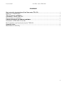
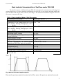
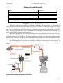
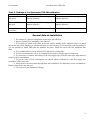
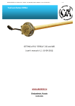
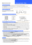
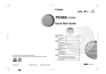
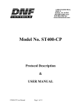
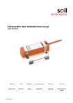
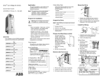
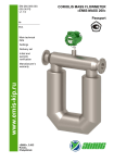
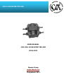
FUEL FLOW METER TRD-500
USERS MANUAL
FOR FUEL FLOW METER TRD-500
03.04.2011
Sapsan Group
www.skontrol.ru
Chelyabinsk 2011
User manual
fuel flow meter TRD-500
Content
Main technical characteristics of fuel flow meter TRD-500 ............................................................... 3
Delivery in complete sets ...................................................................................................................... 4
TRD-500 sensor installation .................................................................................................................. 4
Calibration of sensor TRD-500 ............................................................................................................. 5
General data on installation .................................................................................................................. 6
General instructions on pipelines installation ...................................................................................... 7
Connection of TRD-500 to recorder ..................................................................................................... 8
Final inspection and functional check of TRD-500 ............................................................................. 9
Operation notes ..................................................................................................................................... 9
Manufacturer's warranty ....................................................................................................................... 9
2
User manual
fuel flow meter TRD-500
Main technical characteristics of fuel flow meter TRD-500
The fuel flow meter of differential type TRD-500 is designed for measurement of flowing fuel
volume and delivery of electric impulses at installation in a fuel line of cars, tractors and other mobile and
fixed machines and integral units (vehicles) according to the differential installation diagram. The fuel
flow meter is nonrepairable item.
Table 1. Basic technical data of fuel flow meter
Measured fuel flow range
Number of measurement channels
Conformity of one output pulse «К1» with
fuel volume, flowing through port «К1»,
…….. l/pulse.
Conformity of one output pulse «К2» with
fuel volume, flowing through port «К2»,
…….. l/pulse.
Basic percentage error of fuel metering
Operating supply voltage
Power supply voltage range, that provides
normal operation
Useful current, no more
Digital output
Ambient temperature, at which normal
operation of fuel flow meter is provided
Dimensions, mm, not above
Weight not above
Run time of fuel flow meter
Average time to failure, not less
Ingress protection rating of fuel flow
meter, not less
from 30 to 500 l/h.
2 (supply and return flow).
150… 250
150… 250
± 1 %.
12/24V.
10-30 V.
50 mА.
impulse, open collector.
From- 40 to + 65 0С.
67х73х100,5.
0,5 kg
twenty-four-hour
12500 hours
IP68.
Fig. 1 Data on flow meter impulse response
Data on the precious materials content in fuel flow meter: No precious materials are used.
3
User manual
fuel flow meter TRD-500
Delivery in complete sets
Name
Quantity
TRD-500
Wiring extender with interconnect plug *
Hose adapters **
Joint washers **
Certificate
* Wire length is agreed when ordering
** It is supplied in agreement with buyer
1 piece.
1 piece.*
4 pieces.**
4 pieces.**
1 piece.
TRD-500 sensor installation
TRD-500 is installed according to the differential installation scheme (see fig. 2). Thus the fuel
system undergoes no modifications, except for insertion of two sections of TRD into a supply and return
lines. The first section is installed between the fine filter and high-pressure fuel pump; the second one
(back flow) is installed into return flow line after a connection point connected high-pressure fuel pump
return flow and jet return flow. Fuel consumption is determined as an indications difference of
measurement chambers of supply and return flows.
TRD-500 is inappropriate for engines at which fuel flows from back flow line with some air (some
engines with HP ТНВД a high pressure). In such engines measurement accuracy of back flow can be
essentially reduced because of the air. To define whether there is some air at back flow you should sink
back flow hose in transparent capacity to the bottom and watch whether fuel comes out with bubbles and
foam while capacity filling.
The following things are necessary for installation: TRD-500, installation kit, a drill, a key set, a
fuel-resistant hose, a knife to cut the hose, a bracket and self-tapping screws (bolts to fix the device to a
bracket).
Fig. 2 Principle installation diagram for TRD-500.
4
User manual
fuel flow meter TRD-500
Calibration of sensor TRD-500
Sensor TRD-500 has various coefficient values at various flow rates. At present coefficient
adjustment with the built-in controller isn't carried out. Therefore, to increase the measurement accuracy it
is necessary to calibrate the sensor at the car.
General installation sequence with system calibration:
1. Choose the place for installation proceeding from the convenience of a pipeline running and general
data on TRD installation. (See section “General instructions on pipelines installation”).
2. Fix the sensor on the car (on a bracket or integral unit of the car).
3. Install a magnetic filter on a return pipe.
4. Connect section of return flow measurement. Both sections are identical. Choose which section to
install into supply line and which one into return line depending on the convenience of pipelines
running.
5. Temporarily connect section of supply measurement in sequence with section of return
measurement on the return pipe (see fig. 3).
6. Disconnect a return pipe from a tank and direct it into an auxiliary tank (see fig. 3).
7. Connect both chambers of the flow meter to the impulse counter. You may use the DailyScan
computer of SapsanVneshTrog production to count the impulses. You may also use the recorders that
enable to see current values of the impulse counter (for example, Autograph terminal when it’s
connected to the AutoGRAPH_control.exe program). If you use the DailyScan computer as the
measuring tool you should do the following: temporarily set both coefficients equal to 1 and choose
the fuel rate display mode at calibration.
8. Empty a measuring tank 10 liters in volume. Direct the return pipe to the auxiliary tank. Start the
engine and set on idle rpm. Displace a hose in a measuring tank and at the same moment notice
current indications of both counters. After the measuring tank is filled place a hose back and notice
the indicators at this moment. Enter the data in the table 1 and calculate k1 and k2.
9. Empty the measuring tank and repeat the calibration on load rpm (2000 rpm). Enter the data in the
table and calculate к1 and к2.
10. Reconnect supply section to a supply pipe (see fig. 2) and place a supply pipe back in the tank.
11. Pump over engine fuel system, start the engine and check working capacity.
Fig. 3 Installation diagram of TRD-500 at calibration.
5
User manual
fuel flow meter TRD-500
Table 2. Findings of fuel flow meter TRD-500 calibration
Section 1, liter/impulse
Section 2, liter/impulse
Flow coefficient at k1хх=capacity of measuring tank k2хх= capacity of measuring tank /
idle speed
/impulse quantity=
impulse quantity =
Flow coefficient
load rpm
Average low
coefficient
at k12000= capacity of measuring tank / k22000= capacity of measuring tank /
impulse quantity =
impulse quantity =
k1=0,25*k1хх+0,75*k12000=
k2=0,25*k2хх+0,75*k22000=
General data on installation
1. The content of a gaseous component in fuel lines isn't allowed.
2. Ingress of particles at installation isn't allowed.
3. It is required to install a fuel filter before the supply chamber and a magnetic trap for a metal
dust before the return chamber (to catch metal dust of worn out parts of fuel injection pump assembly). If
it is not possible to install TRD after the standard fine filter, install the sensor after the additional fine
filter.
4. It is recommended to seal up all fuel lines and electric connections.
5. It is not recommended to use it in Common Rail systems with open type fuel-injectors.
6. It is necessary to subtract indications of the fuel supply pipe from the return pipe indications to
found out fuel consumption.
7. To get the value of fuel consumption you should subtract indications of the fuel supply line
from those of the return line.
8. A direction of fuel movement through flow meter chambers are marked by arrows on chambers.
Return connection is not allowed.
9. Use only steel (not aluminum) fittings!
6
User manual
fuel flow meter TRD-500
Fig. 4 choice of the installation plane.
General instructions on pipelines installation
1. Fuel lines should be laid on a vehicle in a reliably environment-proofed way and at break of their
hermiticity there should be no fire danger (they should be laid under a collector/turbine not over
them).
2. Protection of fuel lines from contact with sharp edges of integral units of the car and break stones
flying out from under wheels should be provided;
3. Fuel lines should be a little bit longer to make up temperature changes of length;
4. It is not allowed to reduce internal profile of fuel lines at bending.
5. Fuel lines should be mounted on the vehicle with couplers (clamping devices) which don't damage
a tube and allow temperature changes of fuel lines length.
6. It is not recommended to mount TRD on parts of vehicle that undergo a strong vibration and
heating.
7. Keep flanges and TRD connection carvings clean! Don't touch their surface with dirty hands. At
installation don't let dust and water ingress in a flow meter.
7
User manual
fuel flow meter TRD-500
Fig. 4 An example of sensor installation on JAMZ engine
Connection of TRD-500 to recorder
Fig. 5 TRD-500 sensor slot
Wire marking and sensor socket:
Contact
Contact use
into split
1
“-” power
2
“+” power
3
K1 (left chamber from
wire)
4
K2 (right chamber from
wire)
Color of internal sensor Color of Wiring extender
wires
Brown
Brown
Red
Blue
Grey
Yellow green
Violet
Black
8
User manual
fuel flow meter TRD-500
Final inspection and functional check of TRD-500
Wipe all new connections of fuel lines and check whether there is no fuel accumulation next to an
exhaust system (muffler).
Take all tools, material rests, flooring and rags away from a vehicle. If it is necessary, close an
engine department, lower a driver’s cabin.
On engine operating indoors provide reliable removal of exhaust gases through exhaust
ventilation.
Start the engine and set constant frequency of rotation idling.
Pay attention on the engine operation resistance. Check whether the engine reacts on a gas pedal
and comes back to idling when you release it.
Instability of engine rpm points to problems in fuel line system (in additionally installed filter or
bad pumping of fuel system).
On engine operating evaluate visually hermiticity of all fuel line connections.
Stop the engine and check whether there is no fuel leak and air drain in all union joints of fuel
system, the sensor and the additional filter.
Fuel leaking in joining places of fuel lines isn’t allowed.
Don't try to tight the joint places. Use new copper joint washers to tight it!
Plugging fuel system leaks should be carried out only at dead engine! In no case try to
tighten the joint places at engine running!
If there is no fuel consumption indications (the consumption is equal to zero) it is recommended to
check rotation of TRD mechanism through blowing it off by air. If necessary replace TRD.
Operation notes
ATTENTION! At work with a flow meter it is necessary to carry out following restrictions:
Do not apply power supply voltage exceeding +30 V on a flow meter;
Do not allow polarity violation of connected supply voltage.
Manufacturer's warranty
The manufacturer guarantees the conformity of a flow meter to requirements of the design documentation
while meeting the requirements of installation, service rules, transportation and storage rules by customer.
Guaranteed storage life is 2 years from the manufacturing date. As the manufacturing date the date
specified on a flow meter (in the certificate) shall be taken.
Guarantee period is 24 months from the date of introduction into service, but no more than 30 months
from the manufacturing date.
During a guarantee period the manufacturer undertakes the obligation to replace a flow meter for free in
case of defects and failures occurrence.
The guarantee period is prolonged for the period from the claim submission to flow meter setting into
operation after replacement.
The address of the manufacturer:
"Sapsanvneshtorg" Ltd, Tel. 8 (351) 247-75-58, 454081, Russia, Chelyabinsk, Rossiyskaya str., 194
www.skontrol.ru
9