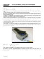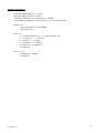
1
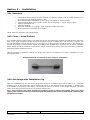
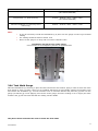
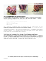
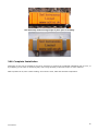
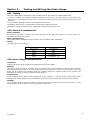
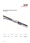
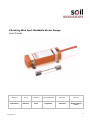
Vibrating Wire Spot Weldable Strain Gauge User Manual Man126 6.0.2 04/08/14 Chris Rasmussen Phil Day Phil Day Manual No. Revision Date Originator Checked Authorised for Issue User Manual 1 Contents Section 1 : Foreword, Introduction & Operating Principle ............................................................ 3 1.01 1.02 Introduction .................................................................................................................. 3 Operating Principle ........................................................................................................ 3 Section 2 : Sensor, Pick-up and Spot Welder Description ............................................................. 4 2.01 2.02 2.03 2.04 2.05 2.06 2.07 Components ................................................................................................................. 4 Spot Weldable Strain Gauge ........................................................................................... 4 Electromagnetic Coil Assembly with Cable ........................................................................ 5 Vibrating Wire Readout/Data Logger ................................................................................ 5 Strain Gauge Installation Jig & ‘Quick Set’ Clip .................................................................. 5 General Purpose Tools.................................................................................................... 6 Spot Welder .................................................................................................................. 6 Section 3 : Installation ................................................................................................................. 8 3.01 3.02 3.03 3.04 3.05 3.06 3.07 3.08 3.09 Overview ...................................................................................................................... 8 Clean / Grind Surface ..................................................................................................... 8 Set Gauge with Installation Jig ........................................................................................ 8 Tack Weld Gauge........................................................................................................... 9 Remove Jig and Complete Welding ................................................................................ 10 Set Gauge with ‘Quick Set’ Clip ..................................................................................... 10 Gluing Gauges (use of Epoxy resins) .............................................................................. 11 Place Coil Assembly Over Gauge, Check Reading and Secure ............................................ 11 Complete Installation ................................................................................................... 12 Section 4 : Testing and Wiring the Strain Gauge ........................................................................ 13 4.01 4.02 4.03 Testing ....................................................................................................................... 13 General Considerations ................................................................................................ 13 Strain Gauge Considerations ......................................................................................... 13 Section 5 : Taking Readings (Using Soil Instruments Readout) ................................................. 14 5.01 5.02 5.03 Sensor connection ....................................................................................................... 14 Selecting Displayed Units ............................................................................................. 14 Selecting Sweep Range ................................................................................................ 15 Section 6 : Data Reduction ......................................................................................................... 16 6.01 Converting from Hz to microstrain ................................................................................. 16 Section 7 : Temperature Effects ................................................................................................. 18 User Manual 2 Section 1 : Foreword, Introduction & Operating Principle It is essential that this User Manual is read and understood by suitably qualified technicians before undertaking the installation of Vibrating Wire Spot Weldable Strain Gauges. Although no specialist welding skills are required for spot welding the gauge, familiarisation with the equipment and some initial practice to develop a feel of clean spark-free spot welding must be acquired by following the instructions given in this manual. The description of surface preparation and safety instructions must also be well understood and adhered to, to ensure the gauge provides a high level of data quality for satisfactory results. The instructions given in this manual form basic guidelines to help install and read the vibrating wire strain gauges. Modifications to these procedures demanded by varied situations can be based on sound engineering judgement with due regard to safety. 1.01 Introduction The Vibrating Wire Spot Weldable Strain Gauge is a simple device for measuring strains in the steel elements of a structure. Common applications are found in steel elements of bridges, tunnel linings, pile foundations, retaining wall reinforcing structures, building structures etc. The most common means of installation of these gauges is by spot welding directly onto the steel member. In certain applications bonding, using suitable adhesives can be employed for mounting these gauges. For more details of this and suitable bonding agents, please contact Soil Instruments. This manual describes the operating principle, basic components and construction of the gauge, the procedure to prepare, install and read the gauge together with basic troubleshooting suggestions. 1.02 Operating Principle The Strain Gauge employs the Vibrating Wire principle. A high tensile steel wire when held under tension between two points and “plucked” will vibrate at its natural resonant frequency. The frequency of vibration is a function of the tension of the wire. As two end blocks gripping the ends of the wire are fixed to a steel structure, the tension in the wire will change as the distance between two blocks varies as a result of strain in the steel member. The changes in strain can be used to calculate load and stresses in the structural member. User Manual 3 Section 2 : Sensor, Pick-up and Spot Welder Description 2.01 Components The components of the system are identified below:Soil Instruments Handheld VW Readout (not included with strain gauges) Pickup Coil Assembly Retaining Coil Straps for Pickup Strain Gauge Assembly Strain Gauge Installation Jig (Inset ‘Quick Set’ Clip) 2.02 Spot Weldable Strain Gauge The gauge consists of the following components; Two end blocks fitted with circular welding flanges to which each end of the vibrating wire is securely fixed. The wire is enclosed into an outer tube made of User Manual 4 stainless steel. Two 'O' ring seals between the outer tube and the end blocks provide water-proofing rated to 7 bar external pressure. The wire is tensioned by fitting a Strain Gauge Installation Jig over the gauge before welding it to the prepared surface of the member to be monitored. The gauge must be connected to a readout during this operation so that the correct tension can be applied. Spot Weldable Strain Gauge 2.03 Electromagnetic Coil Assembly with Cable The Electromagnetic coil assembly in conjunction with a suitable readout is used to “pluck” the wire and read the frequency at which it vibrates. The assembly consists of an electromagnetic coil and a thermistor. The coil and thermistor are connected to a four core shielded cable. The complete assembly is encapsulated in a plastic mounding to fit snugly on top of the welded gauge. Once positioned over installed gauge the coil assembly can be secured to the base metal structure by spot welding retaining straps, cable ties and quick setting epoxy resins and, in some cases, pipe clips. Coil Assembly 2.04 Vibrating Wire Readout/Data Logger A Vibrating Wire Readout is required to test, install and read the Vibrating Wire Spot Weldable Strain Gauges. Detailed instructions to use the readout/ logger are given in the equipment's own operating manual. The thermistor gives an analogue output in ohms which can either be read using a digital voltmeter or alternatively an Soil Instruments Handheld Readout or Logger. 2.05 Strain Gauge Installation Jig & ‘Quick Set’ Clip Two methods are available for pre-tensioning the strain gauge, the Strain Gauge Installation Jig and the Quick Set Clip. Typically the Jig is used where the installer accurately wishes to place the gauge at a known position to allow for tension or compression. The Clip provides a quick and easy way to set the gauge to its approximate middle point. The Jig, pictured below is used to pre-tension the gauge prior to installation. Dependent on the expected strain change () in the steel to be monitored, the gauge can be set for tension, compression or at midpoint – full details are in Section 3.03 User Manual 5 The Quick Set Clip, pictured below in place on the gauge is used to set the gauge to its approx. mid-point before installation, please see section 3.06 for details of its use 2.06 General Purpose Tools The tools required can vary from application to application and with the number of gauges to be welded. The following tools will help in a quick and efficient preparation. Electric Angle Grinder with grinding and sanding discs (together with safety gloves and goggles) Hand Tools – files, wire brush, emery strips, etc. Cleaning and Degreasing solvents and materials. Silicon Sealant Silastic 732 RTV or Cyanoacrylate Adhesive (Super Glue). A flat piece of metal measuring 90 x 45mm for use as template to check size and flatness of the gauge mounting surface area. (This could be cut from a 150mm steel rule). 2.07 Spot Welder This is a portable battery or mains powered spot welder capable of welding up to 0.010" thick stainless steel shim sheet to base metal of structure. Units are available for hire from Soil Instruments. It is advisable to use the length of 0.15mm thick stainless steel strip similar to strain gauge and coil mounting flanges for practising and testing of spot weld strength. Use of the spot welder is quite simple. Connect the earthing cable to the main body of the structure. Wear eye protective goggles. Switch the welder on. For battery operated AVT unit ensure that battery is fully charged. Select medium energy level. User Manual 6 Place a piece of shim strip on the prepared surface and place the welding probe in its centre. Apply gentle but firm pressure. The welder will operate when it is triggered achieving one spot weld. Pull the strip off. If the strip tears off leaving a hole in it, the weld is satisfactory, otherwise increase the energy level and repeat test. Once energy setting is correct, weld the strip using three or four spot welds in a line and do a pull test. Switch off the welder and disconnect earth connection. Note: User Manual Loose and unclean earthing may result in poor quality welds. Unclean and too pointed tips will cause their fusion to the shim metal. If a spark is seen when making the weld, reduce the energy setting on the welder. Keep the tip clean and slightly radiused by rubbing it on fine emery sheet. 7 Section 3 : Installation 3.01 Overview Clean/grind surface gauge is to be installed on, ensuring (in the case of circular material such as reinforcing bar) that the surface is flat Place Strain Gauge Installation Jig over gauge and adjust to desired tension ‘Tack’ gauge to steel using 3 welds at each end of the gauge – or glue gauge in place Remove Installation Jig Complete welding Place Coil Assembly over gauge, check reading is stable and secure Protect gauge/coil assemble as necessary These steps are covered in more detail below. 3.02 Clean / Grind Surface It is essential that the gauge tube is not deformed by the end pads being welded to material which has more than a very slight curvature. On flat structural members such as ‘I’ beams this is not normally a concern, but for round elements such as pile casings or reinforcing bar, an angle grinder should be used to gain as flat as a surface as possible. If a flat surface cannot be created, then another form of gauge such as an Arc Weldable Strain Gauge should be considered. The surface can be cleaned using emery cloth and if needed a proprietary degreasing agent suitable for steels. Once the surface is prepared, position the gauge and check for orientation and surface suitability as in the photograph below. Gauge positioned on cleaned surface ready for installation 3.03 Set Gauge with Installation Jig Place the installation Jig over the strain gauge and connect to a readout device set to read in Hz. Using the machine screw at the right hand end to tension the gauge to the desired tension depending on whether the steel member is likely to go into tension, compression or if this is uncertain, to the gauge mid-point. The table on the next page gives an idea of the Hz values to achieve this. Note: Take extreme care when turning the machine screw to tension the gauge, after more than approx. two turns from the non-tensioned (low Hz) position the wire may well break, rendering the gauge unserviceable. Expected User Manual Turn Machine Screw To Set Approx. Gauge Reading 8 In Hz Tension (i.e. steel lengthens) 1660Hz -1640Hz / 2755 - 2680 f2/1000 (20% RATIO SETTING) Compression (i.e. steel shortens) 2715Hz - 2695Hz / 7371 - 7263 f2/1000 (20% RATIO SETTING) Unknown midpoint (i.e. steel may move either way) 2250Hz - 2230Hz / 5062 - 4973 f2/1000 Note: It may be necessary to hold the Installation Jig in place over the gauge in order to get a stable reading The reading should be stable to within 1Hz Never set the gauge to a range with more than a 80/20% ratio Installation Jig placed over strain gauge; note machine screw for adjusting tension on right hand side 3.04 Tack Weld Gauge With the Installation Jig remaining in place and still connected to the readout, apply 3 welds to each end of the stain gauge to ‘tack’ it in place. Once you are confident that these are good welds, slacken the machine screw and remove the Installation jig. Turn the machine screw to minimum tension and place the jig back over the gauge (so that the jig is now applying zero tension to the gauge) check the reading in Hz is roughly the same as before the jig was removed and that the reading remains stable. The photos below indicates the areas to make the tack welds. User Manual 9 Tack weld where marked (3rd position hidden under cable in photograph) Tack weld where marked 3.05 Remove Jig and Complete Welding Remove the Installation Jig and store in a secure place ready for the next installation. Place a minimum of 15 welds on each pad at either end of the gauge, evenly spaced to ensure that all of the change in stress of the steel being monitored is transmitted evenly to the gauge. An example of a correctly welded end pad on reinforcing bar 3.06 Set Gauge with ‘Quick Set’ Clip To use the Quick Set Clip in place of the Installation Jig, place the Quick Set Clip over the gauge and then glue or weld the gauge to the surface to be monitored. Once the glue has fully cured, (or immediately after making tack welds if welding), remove the Quick Set Clip and proceed as set out in 3.08 and beyond. Note: Use of the Quick Set Clip will place the gauge approximately at its mid-point. User Manual 10 3.07 Gluing Gauges (use of Epoxy resins) In certain applications where spot welding is not feasible i.e. gauging of concrete, cast iron or nonferrous materials, possibilities of bonding by epoxy resins such as HBM X60 may be considered. A successful installation, by bonding, will depend on a number of factors such as: Nature and physical characteristics of structure material. Selection of epoxy resin. Operating temperature ranges. Operational life. Due to complexities of temperature effects on composite epoxies and changes in these long term characteristics, each application requires to be treated as a special case and is not in the scope of this manual. Guidance may be sought from Soil Instruments. for such individual application To install a gauge using Epoxy or other glues, follow the guidelines in 3.01 and 3.02 above ensuring that the gauge and the surface it is to be attached to are free from any dust, grease, oil or any deposits which may prevent the glue from coupling the gauge rigidly to the surface. 3.08 Place Coil Assembly Over Gauge, Check Reading and Secure Once the welding or gluing is complete, place the Coil Assembly over the gauge, connect it to a readout and check that the reading is (a) stable and (b) broadly the same as when the Installation Jig was in place. You may need to hold the Coil Assembly in place to do this. If all okay, then secure the Coil Assembly by the desired method. For steel such as ‘I’ beams it is recommended that the stainless steel securing straps are welded in place to secure the assembly, on reinforcing bar, cable ties or tape may be used. Coil Assembly placed over strain gauge (on reinforcing bar) to check readings User Manual 11 Coil Assembly with securing straps in place prior to welding 3.09 Complete Installation Depending on the site circumstances it may be necessary to protect the completed installation with a cover, or by wrapping (in the case of reinforcing bar) with a large quantity of protective tape or other material. Most important of all, take a base reading, and note the time, date and ambient temperature. User Manual 12 Section 4 : Testing and Wiring the Strain Gauge 4.01 Testing Test each sensor before installing it. Use a readout and an ohm meter to conduct these tests. • Connect a readout (see manual readout instructions). Pull, but do not twist, gently on the ends of the gauge. The Hz reading should be seen to increase as the ends are pulled and decrease as they are released. • The thermistor reading should be near ambient temperature. • Resistance between the red and black leads should be about 180 ohms. • Resistance between white and blue leads should be about 3k ohms at 25C 4.02 General Considerations Sensor Handling: Do not twist, pull hard or attempt to remove the pads on the ends of the sensor. This may cause nonrepairable damage to the sensor. Sensor Identification: Mark cables before installation so that sensors can be identified after installation. Wiring: The gauge wires are as follows:Wire Colour Identification Red VW+ Black VW- White Thermistor +ve Blue Thermistor –ve 4.03 Strain Gauge Considerations Orientation: Position the strain gauge so that it is parallel with the axis of loading. Bending: The strain gauge should be installed along the neutral axis of the structural member when possible. Bending will increase strain on one side of the neutral axis and decrease strain on the opposite side. Axial strain can be isolated from bending strain by installing gauges on opposite sides of the member and averaging the change in strain reported by both gauges. Irregularities: Avoid installing strain gauges near irregularities in the member or near the ends of the member since readings from these locations may not adequately represent strain in the other portions of the member. Sunlight: Try to shield gauges from direct sunlight. If the gauge is heated faster than the steel beneath it, it may report changes in strain that are not representative of the steel. User Manual 13 Section 5 : Readout) Taking Readings (Using Soil Instruments 5.01 Sensor connection Remove the dust cap from the connector socket located at the top end of the readout. Store this cap safely. Take the required fly lead and carefully aligning its connector with the socket, push the two together until they ‘click’. The other end of the lead may now be connected to their sensor or switchbox. If using the crocodile clips ensure that red is connected to red and the black crocodile clip to the black (or sometimes blue) sensor wire. The polarity of the thermistor wires (if fitted to the sensor), usually green and white, is not important, but for convention, white connect to white and green connect to green. Make sure that the wires and crocodile clips are lying so that they do not touch each other. If the vibrating wire circuit should ‘short’, the VWH Readout will shut down to protect the circuitry. If connecting to a switchbox via the switchbox flylead, insert the connector into the switchbox socket after careful alignment and select the required sensor via the rotary channel switches. The Handheld Readout is now switched on by depressing and holding the ‘On/Off’ button for about 1 second, until ‘Soil Instruments’ appears on the LCD screen release the on/off button and ‘Handheld VW Readout’ scrolls across the lower row. There will then be a pause of 5 seconds or so, whilst the Readout self-tests and checks after which the upper row will display the vibrating wire reading in frequency and the lower row the sensor temperature in °C. If no thermistor is connected, the message ‘NO THERMISTOR?’ will be displayed, which is just a prompt and maybe ignored if not applicable. Battery compartment & flylead socket 5.02 Selecting Displayed Units When switched on, the Readout always defaults to sensor units of “Frequency” display. If ‘Period’ or ‘Frequency Squared/1000’ display is required, the ‘Units’ button should be pressed and immediately released. The unit type may take up to 2 seconds to change. Pressing the ‘Units’ button again will scroll to the next unit displayed, in the order – Frequency, Period, Frequency2/1000. User Manual 14 5.03 Selecting Sweep Range For accurate and stable sensor readings, we need ensure that the sensor is correctly connected to the Readout and that the selected sweep range encompasses the current sensor wire frequency. If not, readings will not be stable. Similar to the Units button, the ‘Sweep Range’ button should be pressed and immediately released. The LCD display will briefly indicate the Sweep Range number (1 to 4) and the range frequencies (450 to 1250Hz, 800-2000Hz, 1400 to 3500Hz and 2400 to 6000Hz), and then start ‘sweeping’ the sensor wire with the current Sweep Range approximately every 4 seconds. For sweep excitation readout units, set the sweep range to 1000 – 3000Hz. User Manual 15 Section 6 : Data Reduction 6.01 Converting from Hz to microstrain Data from strain gauges is generally presented in micro strain ( length per unit length:- ) where strain is the ratio of the change in ( ) Practical K factor = 3920 (Gauge calibration constant) Conversion of Period and Linear Units to microstrain is carried out using either of the formulae detailed below:Period Units [ Where ( ) ( ) ] = Change in strain in micro-strain = Gauge Calibration Constant = Base reading in Period units x 107 = Current reading in Period units x 107 Please note: when ( ) ( ) is positive the resultant strain is tensile. Linear Units = Where ( - ) ) = Change in micro-strain = Gauge Calibration Constant = Base reading in units = Current reading in Please note: when ( - units ) is positive the resultant strain is tensile. The calculation of Load in a member using data from strain gauges is often complex. The fundamental problem is determining the composite Young Modulus (E) of the member, since it is often difficult to accurately determine the properties of the insitu materials. Once a Young Modulus is calculated, the following equations can be used to calculate the loading on the structural member at the location of the Strain Gauge. Force (F) = Stress (S) x Area (A) Where A = Cross sectional area in m² Where F units = Newton’s Where S units = N/m² Stress (S) = Young Modulus of Elasticity (E) x Strain ( ) Where E units = N/m² User Manual 16 Example calculation Steel pipe outside diameter = 1.016m Steel pipe inside diameter = 0.984m Calculated change from the strain gauges = 54.688 Young Modulus of Elasticity of the steel pipe = 200,000,000,000 N/m² Stress = E x = 200,000,000,000 x 0.000054688 =10937600 N/m² Area = r² = x (outside diameter /2)² - = x (1.016 /2)² - = x (0.508)² - = x 0.258064 - x (inside diameter /2)² x (0.984 /2)² x (0.492)² x 0.242064 = 0.810732 m² – 0.760466 m² = 0.050266 m² Force = S x A = 10937600 x 0.050266 = 549789.4N User Manual 17 Section 7 : Temperature Effects It is best practice to record temperature when you record strain readings. You can then use the temperature data as well as strain data to analyse the behaviour of the structure. The steel used for the wire in the strain gauge has a thermal coefficient of expansion similar to that of structural steel. Thus, if the gauge and the steel have the same thermal coefficient of expansion and are subjected to the same temperature change, corrections for temperature change are not required. If the gauge is heated by direct sunlight, so that its temperature increases faster than that of the structural steel, you may see large changes in apparent strain. It is difficult to correct for this, so try to shield gauges from direct sunlight using thermally insulated covers. If the steel in the structure has a thermal coefficient that is quite different from that of the gauge, the following temperature correction might be appropriate. corrected = ( ) ( ) Where: is the change in strain, is the thermal coefficient of the member is the thermal coefficient of the gauge:11.0 /°C is the current temperature is the initial temperature Bell Lane, Uckfield, East Sussex t: +44 (0) 1825 765044 e: [email protected] TN22 1QL United Kingdom f: +44 (0) 1825 744398 w: www.itmsoil.com Soil Instruments Ltd. Registered in England. Number: 07960087. Registered Office: 5th Floor, 24 Old Bond Street, London, W1S 4AW User Manual 18