1
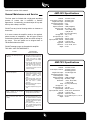
User Manual
AMP-3512 • AMP-7012
12 Channel - 6 Zone Power Amplifier
Description
TRUAUDIO’s 12-channel power amplifier is a perfect
solution for those multi-room audio installations that
require flexibility and quality sound.
With smooth
appearance and versatility, this well-constructed amplifier
has many features to enhance your installation and can
be customized to fit any system. Features include:
individual input sensitivity control for each channel, local
source input for each channel and BUS 1 and BUS 2
source inputs, bridging between channels, and in and out
auto-sensing triggers. The specially designed torroid
transformers and cooling fans will minimize unwanted
heat build-up to ensure the long life of the amplifier.
No matter what brand of controller the system requires,
this 12 channel amplifier will deliver audiophile sound and
maximize your listening experience.
Caution:
MAKE SURE TO READ THIS INSTRUCTION MANUAL
BEFORE TURING THE POWER ON OR HOOKING UP
THIS POWER AMPLIFIER.
Never expose the amplifier to any kind of moisture. This
piece should NOT be used near bath tubs, sinks, wet
basements or swimming pools. Also avoid placing this
unit by heat sources such as radiators, heat registers or
stoves.
This unit should not be in direct sunlight.
Before connecting any cables to the amplifier, the power
mush be OFF.
When deciding on where to place the unit, make sure
there is plenty of airflow. Do not set other components
directly on top of the amplifier. If other components must
be placed on top of this piece, you must use some kind of
spacers. If it will be installed into a cabinet, the cabinet
should have proper airflow. Adding an additional cooling
fan might be necessary.
Make sure the speakers that will be connected to this unit
can handle the output power of the amplifier.
We suggest NOT to use any kind of extension cord unless
it is polarized and made from heavy gauge wire. If at all
possible, plug this unit directly into the wall outlet or surge
protection.
General Information and Features
Front Panel
Power Switch: This is used to turn the unit on or off.
LED Indicators: There is one LED indicator for the power
and each zone. When first turning the power on, the
power LED will come on red and then switch to blue to
indicate the amplifier is in a ready mode, if there is no
audio active to any of the inputs approximately 15
minutes later the power light will turn red to indicate it’s in
sleep mode. Zone LED lights will come on blue as each
zone senses an audio source to the zone input. In case of
a fault to a particular zone the LED changes to RED. If
the fault remains, the corresponding LED remains red. If
the short circuit is momentary then the zone LED changes
to red and then switches to solid blue after a few seconds.
Once all zones are cleared of faults the front LED’s will
turn blue as long as they are active, if no audio source in
present the lights will turn off to indicate the zones are in
sleep mode.
Rear Panel
BUS 1 and 2 Inputs: There are “right” and “left” RCA style
connectors labeled as “1” & “2”. These inputs are used
for sending a single audio source (i.e. CD, Tuner, MP3
etc.) to more than one zone. For using this feature
correctly, see “Amplifier Connection” later in this manual.
BUS 1 & 2 Output: There are “right” and “left” RCA style
connectors labeled as “1” & “2”. These outputs are used
to loop the audio source that is connected to the “BUS
INPUTS” out to a second AMP7012.
Individual Zone Line Inputs: These RCA style input
connectors are the audio inputs for each individual
channel of the amplifier. These inputs are to have audio
sources dedicated to a single channel or zone on the
amplifier. We suggest using a good quality RCA patch
cable for best performance. The RCA inputs are labeled
“Left” and “Right”.
connector, check for any wire strands that might be
sticking out the connection terminal that might cause a
short.
BR/ST Switch: This is used to switch each individual
zone between stereo, or bridged.
These amplifiers are stable down to 4 ohms. The
impedance with the connected speakers should not be
lower than 4 ohms.
BUS/LINE IN switch: this is used to indicate which input
the individual channel or zone will receive audio source
from.
Sensitivity Adjustment: There is an adjustment for the
different
voltage
inputs
with
each
source
(75mVrms-3Vrms). Set the control so that the speakers
are not distorting.
Bridged Connection: The bridging mode is meant for a
single speaker and high power application such as Home
Theater. In the bridged mode the speakers should be 8
ohm minimum.
Make sure the amplifier power is OFF before making
connections.
Speaker Terminals: These Phoenix type terminal
connectors are used to connect the speaker to each
zone.
Connect the right and left outputs from the audio source
to the right or left inputs of the zone you are bridging.
Repeat this for each zone you want in bridged mode.
3-Conductor AC Cord Receptacle: A standard male
receptacle that fits a 3-conductor power cord.
The “BR/ST” switch should be in the bridged (BR)
position. Make sure the switch is in this mode only on the
zones you want bridged.
Amplifier Connection
Always turn off the power of your amplifier,
processor/preamp and all input/playback units before any
connections are made.
Before turning your amplifier and preamp back on, make
sure your volume is turned all the way down.
Remember the cooling issues mentioned earlier in this
manual. Improper airflow will reduce the life of the
amplifier.
When deciding on the final location, keep in mind that
there needs to be adequate space behind the amp to fit
the speaker cables and patch cables.
Stereo Connection: Use a good quality RCA type patch
cord. Connect the right and left output from the processor
to the right and left input jacks on the back of the amplifier.
Repeat this for each channel and/or zone.
The BR/ST switch should be in the “Stereo” position.
Connect the speaker cable coming from each pair of
speakers to the “Speaker Input” connector on the back of
the amplifier. This connecter is removable to make
connection easier. When connecting the cable to the
Connect the speaker cables coming from one speaker to
the “speaker input” connector on the back of the amplifier.
For bridging, one speaker will connect to one connector.
Make sure to follow the labeling on the back of the amp
where the speaker input connector is for the bridged
zone. The speaker input connector is removable to make
connection easier. When connecting the cable to the
connector, check for any wire strands that might be
sticking out the connection terminal that might cause a
short.
BUS 1 & 2 Connection: The BUS inputs are used to
input audio sources such as a preamp, CD, tuner, and
MP3 player over multiple zones. For example, you could
have a CD player on BUS 1 that goes to zones 1, and 2
and a MP3 player going to zones 3, and 4. The other two
zones could have independent input sources. When
designing a single-source, multiple zone system this
mode is perfect. Use a good quality RCA type patch
cord. Connect the right and left outputs from the preamp
to the right and left inputs connectors on the back of the
amplifier. Repeat this for each channel and or zone.
Then, on the zones you want to access one of the BUS
sources, put the input switch into the appropriate setting 1
or 2 position. Proceed to connect the speaker cable to
the amplifier as per the instruction the “Stereo
Connection” section of this manual.
General Maintenance and Service
The front panel is finished with a high-grade anodizing
process to ensure that it maintains a flawless
appearance. Occasionally, you should wipe off any dust
build up with a damp, soft cloth.
DO NOT use any kind of cleaning solution or cleanser on
these units.
If for some reason the amplifier needs to be repaired,
please contact us immediately. We will issue a Return
Authorization Number (RA#) as well as a UPS call tag for
the return. This unit should not be shipped back to
TRUAUDIO without the RA#.
DO NOT attempt to open or dismantle this amplifier.
THIS WILL VOID THE WARRANTY!
SYMPTOM
POSSIBLE CAUSE
AND TEST PROCEDURE
No sound on one channel pair and zone
LED is red.
1. Check that connections are secure and
that there are no loose strands of wire
crossing from positive to negative
terminals at the back of the amplifier
and/or speaker.
2. Disconnect the speaker wire at both
ends. Separate the two conductors at
both ends and test with a meter for a
short circuit. If there is no short,
connect the two conductors at one end
and test for continuity.
Hum from all the speakers.
1. Hum can be caused due to a ground
potential difference between connected
components
(especially
those
connected to antenna or cable TV
feeds).
2. Check for faulty cables, faulty source
signals, an ungrounded phono system,
cable feed, and/or a defective
component.
3. Reverse the AC plug of the components
with non-polarized plugs.
4. Test the AC receptacle using a ground
tester.
Sound is distorted on one or more
channels at normal volume.
1. Check the setting on the SEN/ADJ knob.
You may need to turn down controls.
Bass is weak and stereo sound is
“phasey”.
1. Check that the bridging switch is “off”. If
two adjacent channels are connected
normally but the bridging switch is set to
the bridged position, the two speakers
will be out of phase.
2. The speakers may be wired out of
phase. Recheck polarity and reverse
the connections on the back of one
speaker if necessary.
AMP-3512 Specifications
Channels:
Power Output, Continuous:
Bridged Power Output:
Total Harmonic Distortion:
Channel Separation:
Signal to Noise Ratio:
Frequency range:
IM Distortion:
Safety:
Damping factor:
Input Impedance (all):
Input Sensitivity:
Input requirements, domestic:
Trigger IN:
Trigger OUT:
Dimensions:
Weight:
12 channels, 6 zones
35 watts/ch @ 8 Ω
90 watts/ch @ 8 Ω
0.01%
>-80dB
>-89dB (A weighted)
5Hz - 74kHz (+/- 3dB)
< 0.03% 19kHz,20kHz,
1:1(IHF),RL+8Ω
ETL, CE (or CB scheme)
7261 (+/- 10%)
>17k Ω
75mVrms - 3Vrms
120VAC, 50-60Hz
3 - 30V AC or DC
12VDC out w/100mA
3.9” H, 16.4” W, 14.5” D
27.5 lbs
AMP-7012 Specifications
Channels:
Power Output, Continuous:
Bridged Power Output:
Total Harmonic Distortion:
Channel Separation:
Signal to Noise Ratio:
Frequency range:
IM Distortion:
Safety:
Damping factor:
Input Impedance (all):
Input Sensitivity:
Input requirements, domestic:
Trigger IN:
Trigger OUT:
Dimensions:
Weight:
12 channels, 6 zones
70 watts/ch @ 8 ohms
90 watts/ch @ 4 ohms
120 watts/ch @ 8 ohms
0.01%
>-80dB
>-98dB, (A Weighted)
5Hz-74kHz (+-3dB)
< 0.03%, 19kHz, 20kHz,
1:1 (IHF), RL+8Ώ
ETL, CE (or CB Scheme)
150
>17k ohms
45mVrms ~ 3Vrms
115VAC, 60 Hz / 230VAC 50Hz
3 - 30V AC or DC
12VDC out w/ 100mA
H 6 3/4” (with feet), W 17”, D 16 1/2”
47.5 lbs.
WARNING
• TO PREVENT FIRE OR SHOCK HAZARD. DO NOT EXPOSE THIS APPLIANCE TO RAIN OR MOISTURE.
• THIS APPLIANCE SHALL NOT BE EXPOSED TO DRIPPING OR SPLASHING WATER AND THAT NO OBJECT FILLED
WITH LIQUIDS SUCH AS VASES SHALL BE PLACED ON APPARATUS.
This symbol is intended to alert the user to the
presence of uninsulated "dangerous voltage"
within the product's enclosure that may be of
sufficient magnitude to constitute a risk of electric
shock to persons.
WARNING: TO REDUCE THE RISK OF ELECTRIC SHOCK,
DO NOT REMOVE COVER (OR BACK).
NO USER-SERVICEABLE PARTS INSIDE.
REFER SERVICING TO QUALIFIED SERVICE PERSONNEL.
This symbol is intended to alert the user to the
presence of important operation and maintenance
(servicing) instructions in the literature
accompanying the appliance.
IMPORTANT SAFETY INSTRUCTIONS
1) Read Follow and Keep these instructions
2) Heed all warnings.
3) Only connect this apparatus to a grounded outlet.
4) Ensure the main plug is undamaged, and fully functional as a disconnect device.
5) Do not use this apparatus near water.
6) Clean only with dry cloth.
7) Do not block any ventilation openings. Install in accordance with the
rnanufacturer's instructions.
8) Do not install near any heat sources such as radiators, heat registers, stoves,
or other apparatus (including amplifiers) that produce heat.
9) Do not defeat the safety purpose of the polarized or grounding-type plug. A
polarized plug has two blades with one wider than the other. A grounding
type plug has two blades and a third grounding prong. The wide blade or the
third prong are provided for your safety. If the provided plug does not fit into
your outlet, consult an electrician for replacernent of the obsolete outlet.
10) Protect the power cord frorn being walked on or pinched particularly at plugs,
convenience receptacles, and the point where they exit frorn the apparatus.
11) Only use attachments/accessories specified by themanufacturer.
12) Use only with the cart, stand, tripod, bracket, or table
specified by the manufacturer, or sold with the
apparatus. When a cart is used, use caution when
rnoving the cart/apparatus combination to avoid
injury frorn tip-over.
13) Unplug this apparatus during lightning storrns or
S3125A
when unused for long periods of tirne.
14) Refer all servicing to qualified service personnel. Servicing is required when
the apparatus has been damaged in any way, such as power-supply cord or
plug is damaged, liquid has been spilled or objects have fallen into the
apparatus, the apparatus has been exposed to rain or moisture, does not
operate normally, or has been dropped.
SoundVision Technologies dba TRUAUDIO
PRODUCT WARRANTY
All in-wall, in-ceiling, outdoor speakers, volume controls and freestanding loudspeakers have a limited lifetime warranty. This
warranty includes lifetime parts and repair labor on all components. Powered subwoofers and active electronics have a one (1) year
limited warranty. This warranty includes one (1) year parts and repair labor on all components. TRUAUDIO’s obligation under these
warrantees is limited to repairing or replacing any component found defective in material or workmanship under normal conditions of
use. These warrantees shall not apply to products which have been abused, modified, disassembled, or repaired by anyone other
than TRUAUDIO or one of its appointed service centers. Products to be repaired under this warranty must be returned to the factory
or designated service center with all transportation and insurance charges pre-paid.
It i s the polic y of T R U A U D IO to c o n ti n u o u s l y i ncorporate i mprovements i nto our products. A l l spec if icat ions ar e
su bjec t t o c hange w i th o u t n o ti c e . If y o u h a ve any questi ons regardi ng thi s or any other TR U A U DI O pr oduct s,
p l e a s e c a l l 1 -8 8 8 -8 5 8 -1 555, Monday – Fri day, 7:00 am – 6:00 pm MS T.
T R U AU D IO S p e a ker S ystems, S t. George, U tah, 84790
Offi c e : 4 3 5.986.1574 Fax: 435.251.9815