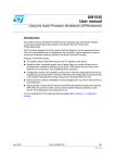
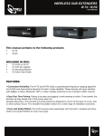
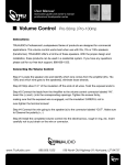
1
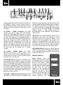
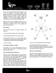
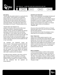
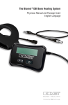
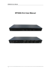
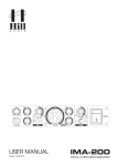
USER MANUAL
AMP-440
4 Channel / 2 Zone
Compact Media Amplifier
1. Read these instructions – All the safety and operating
instructions should be read before this product is operated.
2. Keep these instructions – The safety and operating
instructions should be retained for future reference.
3. Heed all warnings – All warnings on the appliance and in
the operating instructions should be adhered to.
4. Follow all instructions – All operating and use
instructions should be followed.
5. Do not use this apparatus near water – The appliance
should not be used near water or moisture – for example, in
a wet basement or near a swimming pool, and the like.
6. Clean only with dry cloth.
7. Do not block any ventilation openings. Install in
accordance with the manufacture’s instructions.
8. Do not install near any heat sources such as radiators,
heat registers, stoves, or other apparatus (including
amplifiers) that produce heat.
9. Do not defeat the safety purpose of the polarized or
grounding plug. A polarized plug has two blades with one
wider than the other. A grounding plug has two blades and
a third grounding prong. The wide blade or the third prong
is provided for your safety. If the provided plug does not fit
into your outlet, consult an electrician for replacement of
the obsolete outlet.
10. Protect the power cord from being walked on or
pinched particularly at the plugs, convenience receptacles,
and at the point where they exit from the apparatus.
11. Only use attachments/accessories specified by the
manufacturer.
12. Use only with the cart, stand, tripod, bracket,
or table specified by the manufacturer, or sold
with the apparatus. When a cart or rack is used,
use caution when moving the cart/apparatus
combination to avoid injury from tip-over.
13. Unplug the apparatus during lightning storms or when
unused for long periods of time.
14. Refer all servicing to qualified personnel. Servicing is
required when the apparatus has been damaged in any
way, such as power supply cord or plug is damaged, liquid
has been spilled or objects have fallen into the apparatus
has been exposed to rain or moisture, does not operate
normally, or has been dropped.
15. CAUTION: These servicing instructions are for use by
qualified service personnel only. To reduce the risk of
electric shock, do not perform any servicing other than that
contained in the operating instructions unless you are
qualified to do so.
16. Do not install this equipment in a confined or building-in
space such as a book case or similar unit, and remain a
well ventilation conditions at open site. The ventilation
should not be impeded by covering the ventilation
openings with items such as newspaper, table-cloths,
curtains etc.
17. WARNING: Only use attachments/accessories
specified or provided by the manufacturer (such as the
exclusive supply adapter, battery etc).
18. WARNING:To reduce the risk of fire or electric shock,
do not expose this apparatus to rain or moisture. The
apparatus shall not be exposed to dripping or splashing
and that objects filled with liquids, such as vases, shall not
be placed on apparatus.
19. WARNING: The mains plug is used as disconnect
device, the disconnect device shall remain readily
operable.
20. This equipment is a Class II or double insulated
electrical appliance. It has been designed in such a
way that it does not require a safety connection to
electrical earth.
21. Correct Disposal of this product. This marking indicates
that this product should not be disposed with other
household wastes throughout the EU. To prevent
possible harm to the environment or human health
from uncontrolled waste disposal, recycle it responsibly to
promote the sustainable reuse of material resources. To
return your used device, please use the return and
collection systems or contact the retailer where the product
was purchased. They can take this product for
environmental safe recycling.
22.
- This lightning flash with arrowhead symbol within an
equilateral triangle is intended to alert the user to the
presence of non-insulated “dangerous voltage” within
the product’s enclosure that may be of sufficient
magnitude to constitute a risk of electric shock.
- Warning: To reduce the risk of electric shock, do not
remove cover (or back) as there are no
user-serviceable parts inside. Refer servicing to
qualified personnel.
- The exclamation point within an equilateral triangle is
intended to alert the user to the presence of important
operating and maintenance instructions in the
literature accompanying the appliance.
DESCRIPTION
INCLUDED IN THE BOX
The Truaudio AMP-440 is the perfect companion for
today’s more discrete home audio installations. With
its many inputs and outputs, combined with a thin
and compact form factor, the AMP-440 is equally at
home behind a flat screen television as it is mounted
in a rack. It is perfect for small home theater or
multi-room installations, or as a compliment to our 12
channel power amplifiers. Fantastic sound quality
from a superior form factor, get ready to put music in
places you only dreamed.
(1) AMP-440 Amplifier
(1) Power Cord
(1) Remote Control
(1) IR Sensor
(2) Mounting Brackets with Screws
Optional Accessories
Rough-in Ring (RW-AMP)
Recessed Can (RB-AMP)
Faceplate (R-AMPFP-1U)
GENERAL INFORMATION AND FEATURES
IMPORTANT SAFETY INSTRUCTIONS
Never expose the amplifier to any kind of moisture.
This product should not be used outdoors, near
bathtubs, sinks, wet basements or swimming pools.
This product is meant for indoor use only.
Avoid placing this amplifier near heat sources such as
radiators, heat registers or stoves.
This amplifier should not be used in direct sunlight.
Before connecting any cables to the amplifier, the
power switch must be in the OFF position.
Locate the amplifier where there is adequate
ventilation to the sides of the amplifier. If the amplifier
is used in a cabinet an additional cooling fan might be
necessary.
The AMP-440 amplifier includes many useful features
such as A/B switching including speaker level inputs,
an optical input for digital stereo decoding, the option
to have most inputs either fixed or variable, and
outputs that track with the main volume so you can
use them to link multiple AMP-440’s or for a powered
subwoofer. Both zones can be bridged for 80W of
power. A convenient remote control is included, as
well as a remote IR sensor so you can mount the
amplifier out of sight and still control it remotely.
The AMP-440 uses efficient digital amplifier modules
and saves additional power by optionally going to
sleep when not in use. It can be woken using the
remote or a 12V trigger signal.
3
2
4
1
Make sure that the speakers that will be connected to
this amplifier can handle the output power from the
amplifier.
Do not use this amplifier with a power receptacle or
extension cord that is not adequately rated to handle
the power requirements of the amplifier, or that will
not allow the blades of the plug to be fully inserted to
prevent blade exposure.
FRONT PANEL (1) Power Switch: Used to turn the
main power to the amplifier on or off.
(2) VOL+ VOL- Buttons: Used to increase or
decrease the volume when the input source is set to
VAR. The volume is controlled across both output
zones and cannot be controlled individually for each
zone. As the volume level is changed, the indicator
light on the front of the amplifier will blink green
rapidly. When the upper volume limit is reached the
indicator light will hold solid green for about 1 second.
When the lower volume limit is reached the indicator
light will hold solid red for about 1 second.
(3) Power Indicator LED: Displays the status of the
amplifier.
Red (solid): Amplifier has been turned off using
the remote. Amplifier is set to TRIGGER and
waiting for a 12V signal.
There is a problem internally with the amplifier.
Red (briefly solid): Lower volume limit has been
reached.
Orange: Amplifier has gone to sleep.
Green (solid): Amplifier is on and functioning
correctly.
Green (flashing): Volume is being changed either
up or down.
Green (briefly solid): Upper volume limit has
been reached.
Off: Main power switch has been turned off.
The amplifier is not plugged in or is not receiving
power.
The fuse has blown and needs to be replaced.
(4) IR Window: Receives IR signals from the remote
control
REAR PANEL
(1) Power Cord Socket: Use only the included power
cord or an equivalently rated power cord. The socket
also contains both the 2.5A/250V fuse, as well as a
spare fuse.
(2) Main Power Voltage Switch: This switch is used
to change the input voltage from 115V/60Hz to
230V/50Hz.
(3) OUTPUT RCA Connectors: The right and left
OUTPUT RCA connectors output a line level signal
similar to the ZONE 1 speaker level output signal. It
tracks proportionally with volume so that it can be
used to provide signal for a powered subwoofer or
other amplified device. It can also be used to link 2 or
more AMP-440’s together to use the same input
source.
(4) INPUT 1A RCA Connectors: Stereo audio inputs
for Zone 1
(5) INPUT 1A Optical Input: Optical TOSLINK
connector for Zone 1. The AMP-440 will automatically
decode an available optical audio signal and
processes it to stereo. This conversion is done
automatically, regardless if the optical signal is stereo,
5.1 surround, or other audio signal bitstream.
(6) INPUT 1B 3.5mm Input: Stereo audio input for
Zone 1
(7) INPUT 1B Phoenix Connector: Speaker level
stereo audio input for Zone 1. This input can be used
to seamlessly combine an existing home audio install
with additional audio sources.
(8) INPUT 2 RCA Connectors: Stereo audio inputs
for Zone 2
(9) FIX/VAR Switches: The FIX/VAR switches for
INPUT 1A and 1B are used to define how the volume
is controlled for the different audio sources. In the FIX
position the volume control on the AMP-440 is set to
MAXIMUM and volume for the audio source must be
controlled at the source component. In the VAR
position the volume control on the AMP-440 is active
and can be controlled using either the front panel
controls or the included remote control.
(10) PRIMARY Switch: The PRIMARY switch is used
to determine which input block, either 1A or 1B, is the
1
2
3
4
9
5
6
7
overriding input during A/B switching. For example, if
the PRIMARY switch is set to 1A and a source is
connected and detected at both input block 1A and
1B, only the source connected to input block 1A will
be played.
(11) ZONE 1 / ZONE 2 Switches: The ZONE
switches are used to switch each zone between
stereo (ST) and bridged (BDG) output. If a stereo
source is connected and the switch for that zone is
set to ST then the source will be played normally. If
the switch is set to BDG, only the left channel from the
source will be played. In order to benefit from the
increased amplifier wattage when set to BDG, the
speaker must only be connected to the outermost
ports on the Phoenix connector for the zone. If the
speakers are connected normally then the output will
be mono from the left channel input at normal
wattage.
(12) LOCAL / GLOBAL Switch: This switch
determines which input is used for zone 2. If the
switch is set to LOCAL then the ZONE 2 RCA inputs
will be used. If the switch is set to GLOBAL then the
input from zone 1 will be used.
(13) TRIGGER Switch: Setting the TRIGGER switch
to ON means that the amplifier is always active (ON)
and never goes into a sleep or powersaving mode.
When set to TRIGGER the amplifier is always inactive
(OFF) unless an appropriate 12V signal is detected. In
the AUTO position the amplifier will to go to sleep
after several minutes of no source being detected at
any input, and wake automatically when a source is
detected for a few seconds.
(14) ZONE 1 / ZONE 2 Phoenix Connectors: These
connectors are used to connect the speakers. Pay
8
10
11
14
12
13
15
16
attention to the proper polarity and connection order
for each speaker. When connecting a pair of speakers
the connection order (from left to right) is R+, R-, L-,
L+. Use this connection in conjunction with the ZONE
switch set to ST for stereo playback. For bridged
playback connect a single speaker across the
outermost ports of the connector with the positive
wire to the left.
(15) IR Port: The included cabled IR sensor can be
connected to this port if the AMP-440 is to be
mounted where the front panel IR window is not
visible from the listening position. For example, if the
amplifier is mounted behind a television you can
connect the included IR sensor to this port and place
the sensor end where it will be visible and able to
receive the infrared signal from the remote control.
(16) TRIGGER IN Port: This port is used to trigger the
amplifier to wake when a 12V trigger signal is present.
It uses a standard 3.5mm mono jack. The 12V signal
can be either AC or DC.
REMOTE CONTROL
Power Button: Turns the
amplifier on or off remotely when
the TRIGGER switch is set to the
AUTO or ON positions. When
turned off using the remote, the
indicator light on the front panel
will glow solid red and the
amplifier will not automatically
wake, even if a source signal is
detected. Pressing the power
button on the remote again will
turn the amplifier on again and
normal
operation
will
be
POWER
VOLUME
AMP-440
resumed.
Volume Buttons: Used to control volume of the
amplifier remotely. The buttons can be held down to
quickly increase or decrease the volume. As the
volume level is changed the indicator light on the front
panel will blink green rapidly. When the upper volume
limit is reached the indicator light will hold solid green
for about 1 second. When the lower volume limit is
reached the indicator light will hold solid red for about
1 second.
A/B SWITCHING
The AMP-440 features A/B switching for zone 1. The
zone 1 inputs are divided into two blocks of inputs,
block 1A and 1B. Only one input should be connected
per block, but both blocks may have one connected
input.
The PRIMARY switch is used to designate which
input block is the primary input in the event that both
input blocks have an active source connected. If only
one source is connected to either input block it does
not matter how the PRIMARY switch is set because
the AMP-440 will automatically choose it to be
amplified. If both input blocks have a connected
source, but only one source is active, the active
source will automatically be chosen to be amplified.
If the PRIMARY switch is set to 1A, and active source
is in the 1A block, it will continue to be amplified, even
if the source connected to block 1B becomes active.
However, if the active source is in the block not
designated as PRIMARY and a second source from
the PRIMARY block becomes active, the AMP-440
will automatically switch to the primary source. If the
primary source is turned off and the secondary source
continues to play, the AMP-440 will automatically
switch back to the secondary source. This switching
can sometimes take as much as 30 seconds to
complete.
USING A UNIVERSAL REMOTE
Consult your Universal Remote instructions for
programming it to work with your AMP-440. If your
universal remote cannot “learn” the functions from
the included remote, you might be able to control at
least the volume by programming your universal
remote for an ILO, Medion, Tevion or Tatung
television set.
OTHER FEATURES
Sleep Mode: The AMP-440 has a power saving sleep
mode. When the TRIGGER switch is set to AUTO and
no signal is present for several minutes the amplifier
will go into sleep mode until a new input signal is
detected. The amplifier does not need to be turned off
using the remote or main power switch during normal
operation.
Connecting a Subwoofer:
Because the RCA
outputs track with the volume of the source being
played they are ideal to use with a powered
subwoofer for a 2.1 stereo system. When connecting
a subwoofer to the outputs, be sure that the receiver
or source outputs a full range stereo signal.
Stereo (Bridged) Mode: You can use the AMP-440
as a 2x80W stereo amplifier by bridging both zones
and setting the LOCAL/GLOBAL switch to LOCAL. To
do so you must use the RCA connection for both
zones and send the right channel signal to input 1A
left channel and the left channel signal to input 2 left
channel. Both outputs must be wired correctly for
bridged output with the right speaker connected to
the ZONE 1 output and the left speaker connected to
the ZONE 2 output.
MOUNTING OPTIONS
There are several options available for mounting your
AMP-440. When choosing a mounting location,
consider the amount of ventilation the amplifier will
receive. The mounting location needs to provide
adequate clearance (about 1”) to the sides of the
amplifier and needs to have a constant supply of fresh
air. If mounting the AMP-440 in a cabinet it may be
necessary to add a ventilation fan to ensure adequate
cooling. Several possible mounting solutions are
described below.
Wall Using Screws: The AMP-440 is designed to be
easily wall mounted in any orientation. Use the
included template to install three (3) appropriately
sized screws 7.75” apart, leaving the heads of the
screws approximately .25” loose for hanging the
amplifier using the cross-shaped keyholes on the
underside of the amplifier chassis.
Wall Using the Supplied L Brackets: Connect the
L-shaped brackets to the sides of the amplifier
chassis using the included screws through the small
holes in the brackets. Using appropriate hardware
you can now mount the amplifier to the wall or other
surface using the slots in the brackets.
Wall Using (Optional) Recessed Box: Mount the
RB-AMP recessed box to the wall according to the
directions included with the recessed box. The
AMP-440 can then be hung inside the box on the
included mounting posts.
Rack Using (Optional) Faceplate: Using the 4
screws included with the (optional) faceplate, attach
the faceplate to the front of the amplifier. The amplifier
can now be mounted in a standard 19” FORGE or
other brand A/V rack.
GENERAL MAINTENANCE AND SERVICE
Occasional dusting or cleaning with a damp soft cloth
is all that is necessary to clean your amplifier. Do not
use any kind of cleaning solution other than water to
dampen the cleaning cloth.
DO NOT attempt to open or dismantle the amplifier.
This will void your warranty. If for some reason the
amplifier needs to be repaired please contact
TruAudio immediately and we will assist you in
returning and/or repairing your damaged product.
This unit should not be shipped back to TruAudio
without a TruAudio issues Return Authorization
number.
TROUBLESHOOTING
Amplifier does not power on.
1. The power switch is not ON or the power cable
is not firmly connected.
2. The outlet is not “live” and is not providing
power to the amplifier.
3. The main fuse has failed and needs to be
replaced.
No sound or output for more than 30 seconds.
1. The amplifier has been turned OFF using the
remote.
2. The TRIGGER switch is not set correctly or the
amplifier is not receiving a 12V signal.
3. One or more cables are improperly connected.
4. There are loose strands of wire making
unwanted electrical connections.
5. The speaker cables or input cables are
damaged and need to be replaced.
Hum coming from the speakers.
1. There is a ground potential difference between
connected components.
2. One or more cables or components are
defective.
3. Signal wiring has been run too close to power
wiring and is not adequately shielded.
Sound is distorted on one or more channels at
normal volume.
1. The speakers are wired incorrectly for the
ST/BDG setting.
2. The speakers are wired out of phase with each
other.
3. The input source quality is poor or the volume is
too low.
AMPLIFIER SPECIFICATIONS
Channels: 4 Channels, 2 Zones
Power Output, Continuous: 40W @ 8 Ohms
Power Output, Bridged: 80W @ 8 Ohms
Total Harmonic Distortion: 0.05%
Channel Separation: >-50dB
Signal to Noise Ratio: >-80dB (A Weighted)
Frequency Range: 6Hz-51kHz@-3dB
Efficiency: 86%
Safety: ETL, CE (or CB Scheme)
Input Impedance (All): 14k Ohms
Input Power: 115VAC, 60 Hz / 230VAC, 50Hz
Trigger IN: 3-30V AC or DC
Dimensions: W 8.9”, D 12.6”, H 1.6”
Weight: 6 lbs.
CONNECTING THE AMPLIFIER
STEREO (BRIDGED) WITH SUB
R out
SOURCE
L out
SWITCH
POSITIONS
+
R in
SUBWOOFER
LEFT SPEAKER
-
+
RIGHT SPEAKER
TV AMPLIFIER WITH A/B SWITCHING
TV
SUBWOOFER
SOURCE 2
OPTICAL out
SWITCH
POSITIONS
R in
L in
STEREO
SPEAKERS
IR SENSOR
TWO ZONE
SOURCE 1
(ZONE 1)
R in
L in
L out
L out
R out
R out
SPEAKERS
(ZONE 1)
SOURCE 2
SWITCH
POSITIONS
SPEAKERS
(ZONE 2)
SoundVision Technologies dba TRUAUDIO
PRODUCT WARRANTY
All in-wall, in-ceiling, outdoor speakers, volume controls and freestanding loudspeakers have a limited lifetime warranty.
This warranty includes lifetime parts and repair labor on all components. Powered subwoofers and active electronics
have a one (1) year limited warranty. This warranty includes one (1) year parts and repair labor on all components.
TRUAUDIO’s obligation under these warrantees is limited to repairing or replacing any component found defective in
material or workmanship under normal conditions of use. These warrantees shall not apply to products which have
been abused, modified, disassembled, or repaired by anyone other than TRUAUDIO or one of its appointed service
centers. Products to be repaired under this warranty must be returned to the factory or designated service center with
all transportation and insurance charges pre-paid.
It i s the polic y of T R U A U D IO to c o n ti n u o u s l y i ncorporate i mprovements i nto our products. A l l specif icat ions ar e
su bj e c t t o c hange w i th o u t n o ti c e . If y o u h a v e any questi ons regardi ng thi s or any other TR U A U D IO pr oduct s,
pl e ase c all 1- 888- 8 5 8 -1 5 5 5 , Mo n d a y – F ri d a y, 7:00 am – 6:00 pm MS T.
TRUA UDI O S peak e r S y s te m s , H u rri c a n e , U ta h, 84737
Offi ce : 435. 986. 157 4 F a x : 4 3 5 .2 5 1 .9 8 1 5