1
What This Document Assumes
Before performing any operations described in this guide, make sure that all the following preparations have
been complete.
All the setups of hardware including assembly and installation of your machine are complete.
All the setups of software including installation of VersaWorks on your computer and connection of your
machine with the computer are complete.
You are familiar with the basic operations of your machine and Versa Works.
For setups and basic operations of your machine, refer to the User's Manual coming with the machine. For
basic operations of VersaWorks, refer to "VersaWorks Quick Start Guide."
R1-100825
Thank you very much for purchasing this product.
To ensure correct and safe usage with a full understanding of this product's performance, please be sure to read through
this manual completely and store it in a safe location.
Unauthorized copying or transferal, in whole or in part, of this manual is prohibited.
The contents of this operation manual and the specifications of this product are subject to change without notice.
The operation manual and the product have been prepared and tested as much as possible. If you find any misprint
or error, please inform us.
Roland DG Corp. assumes no responsibility for any direct or indirect loss or damage which may occur through use of
this product, regardless of any failure to perform on the part of this product.
Roland DG Corp. assumes no responsibility for any direct or indirect loss or damage which may occur with respect to
any article made using this product.
Contents
Contents.........................................................................................................1
Chapter1 Getting Ready......................................................................................3
1-1 Before Starting Operations.....................................................................4
Checking the Tool to Be Used....................................................................................................... 4
Fold Line and Perforated Cut........................................................................................................ 4
Conditions of Media......................................................................................................................... 4
Checking the Workflow................................................................................................................... 5
1-2 Preparing VersaWorks............................................................................6
Starting VersaWorks.......................................................................................................................... 6
Creating a Folder for Saving PS Files.......................................................................................... 6
1-3 Printer Preparations................................................................................7
Printer Preparations......................................................................................................................... 7
Cutting Test Method (for Perforated Cut)................................................................................ 8
1-4 Preparing the Output Data.................................................................... 11
Concept of Output Data Creation.............................................................................................11
Creating Data for Printing............................................................................................................11
Chapter 2 Output...............................................................................................19
2-1 Starting Output.......................................................................................20
Starting the Fold Line.....................................................................................................................20
Starting the Perforated Cut..........................................................................................................21
Chapter 3 Maintenance/FAQ..............................................................................23
3-1 Maintenance.........................................................................................24
Daily Maintenance..........................................................................................................................24
Maintenance of Crease Tool.........................................................................................................24
3-2 What to Do If (FAQ).............................................................................25
What to Do If….................................................................................................................................25
Copyright © 2010 Roland DG Corporation
http://www.rolanddg.com/
1
Copyright and property of this Software and this manual belong to Roland DG Corp. No part of this publication
may be reproduced, stored in a retrieval system or transmitted, in any from or by any means, electronic,
mechanical, photocopy, recording or otherwise, without the prior written permission of the publisher.
VersaWorks is a registered trademark of Roland DG Corp.
Windows is a registered trademarks or trademarks of Microsoft® Corporation in the United States and/or
other countries.
Pentium are registered trademarks of Intel Corporation in the United States.
Macintosh is a registered trademark of Apple Inc.
Adobe, the Adobe logo, PostScript, PostScript 3, and Illustrator are either registered trademarks or trademarks of Adobe Systems Incorporated in the United States and/or other countries. ©2007 Adobe Systems
Incorporated. All rights reserved.
Other company names and product names are trademarks or registered trademarks of their respective
holders.
2
Chapter1
Getting Ready
1-1 Before Starting Operations......................................................4
Checking the Tool to Be Used......................................................4
Fold Line and Perforated Cut.......................................................4
Conditions of Media......................................................................4
Checking the Workflow.................................................................5
1-2 Preparing VersaWorks.............................................................6
Starting VersaWorks.....................................................................6
Creating a Folder for Saving PS Files..........................................6
1-3 Printer Preparations.................................................................7
Printer Preparations.....................................................................7
Cutting Test Method (for Perforated Cut).....................................8
1-4 Preparing the Output Data..................................................... 11
Concept of Output Data Creation...............................................11
Creating Data for Printing...........................................................11
3
1-1 Before Starting Operations
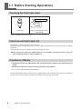
Checking the Tool to Be Used
Crease tool
Cutter for perforated cutting *
(ZEC-U3050)
* This is shipped with a black cap on.
Fold Line and Perforated Cut
The fold line is a feature to make a crease on media.
The perforated cut is a feature to make an external cutoff line by performing "die-cutting" and "half-cutting"
alternately.
Using these features, you can produce product packages and cards.
NOTE: To the areas where the "emboss finish" is performed in printing with gloss inks, you
cannot apply the fold line and perforated cut.
Conditions of Media
Glammage (Thickness) : About 200 to 300 g/m² (Paperboard including clay coated newsback
board)
Width and Length: According to the specifications of your printer
* This is a unit to show the thickness of the paper.
You may not be able to make clear fold lines or cut off the media with some types of media. Be sure to perform
the test in advance to see if you can perform the output with the media as intended.
4
Chapter 1 Getting Ready
1-1 Before Starting Operations
Checking the Workflow
Preparing VersaWorks (P. 6)
Printer Preparations (P. 7)
Adjustments on the printer in accordance with the media to be used
Cutting tests for the perforated cut
Preparing Output Data (P. 11)
Starting the Fold Line (P. 20)
Installing the creasing tool and media
Outputting the data (for printing and fold lines)
Starting the Perforated Cut (P. 21)
Installing the cutter for the perforated cut
Outputting the data (for the perforated cut)
Chapter 1 Getting Ready
5
1-2 Preparing VersaWorks
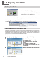
Starting VersaWorks
"On the computer you are using, start VersaWorks. For
information on how to start the program, see the Roland
VersaWorks Quick Start Guide. After starting the program,
go to the upper left of the main screen and check to make
sure that ""Model (or Nickname) of Your Printer"" is displayed,
and that ""Status"" is set to ""Ready to Print."""
VersaWorks Online
This document describes the basic output method to perform the fold line and the perforated cut feature. You
can see other output methods requiring more complicated settings and the latest information of VersaWorks
at VersaWorks Online.
URL : http://dg4.roland.co.jp/en/RVW2forWeb/index.html
VersaWorks Online can be displayed by clicking [help] - [VersaWorks Online] from the main menu.
Creating a Folder for Saving PS Files
In the output printing operation described in this document, the data for the output printing is read out in the
form of a PS file from application software such as Adobe Illustrator, and then the PS file is used for the actual
output. For this reason, it is useful to create a folder in advance for saving the PS files. It is recommended to
locate the folder in the root directory on your computer's local disk.
Procedure
Open [Computer] ( or [My Computer]), and then open [Local Disk (C:)].
For Windows 7:
On the menu, click [New Folder].
For Windows Vista:
On the [Organize] menu, click [New
Folder].
For Windows XP/Windows 2000:
On the [File] menu, click [New], and then
click [Folder].
Enter the name for the folder, and then press
the Enter key.
Here you name "CREASING", for example.
6
Chapter 1 Getting Ready
1-3 Printer Preparations
Printer Preparations
To prepare the printer, various settings and adjustments are to be made according to the media you use. As
the cutting tests are also performed in this section, be sure to use the same type of media here as the one
you use for the actual printing.
For methods to make settings and adjustments, see the User's Manual of your machine.
Procedure
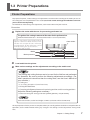
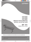
Replace the cutter with the one for processing perforated cut.
The guide of the cutting-in amount of the cutter for the perforated cut
Amount of blade extension = Thickness of the media + 0. 2 mm (maximum)
Turn the cap portion of the blade holder to
adjust the amount of blade extension. Each
indicator tick corresponds to 0.1 millimeters,
and adjustment for 0.5 millimeters can be
made by rotating the cap one full turn.
(Min. 0 mm, Max. 2.5 mm)
Cutter holder
Media
0.2 mm (Max.)
Blade protection
Cutter
Load media into the printer.
Make various settings and the adjustments according to the media used.
The printing and cutting features are to be used for the fold line and perforated
cut operation. Be sure to perform the following adjustments accordingly. (For
other operational instructions than the cutting tests, see the User's Manual of
your machine.)
Cutting test
P. 8, "Cutting Test Method (for Perforated Cut)"
Setting the blade force
Correcting misalignment between the printing positions and the cutting positions
Adjust the following settings as necessary.
Advanced settings for cutting parameters ([SPEED], [OFFSET], and [UP-SPEED])
For the thick media, set the head height at "HIGH." (Indication: Thicker than 0.5mm)
All the preparations for the printer are complete. When you actually perform the fold line and perforated cut
operations, set the media without making any changes in the settings and the adjustments having made
here.
Chapter 1 Getting Ready
7
1-3 Printer Preparations
Cutting Test Method (for Perforated Cut)
When performing the perforated cut, be sure to conduct the cutting test for the perforated cut in advance. The
test method is different from the normal cutting test. Follow the below descriptions to perform the test.
The cutter, media, and test data to be used for the test
Cutter: a cutter for perforated cutting (ZEC-U3050)
Media: the same type of media as the one used for the actual perforated cut operations (in terms
of the manufacturer, thickness, and material).
Test data: "VersaWorks TestPerfCut.ps"
This is contained in the DVD to install VersaWorks. ("DVD-ROM drive (D:)*">"Tools" folder
>"Perforated_Cut_File" folder)
(".ps" may not be displayed depending on the setting of your computer.)
* This is a drive containing the DVD for installation.
Procedure
8
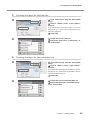
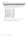
Drag and drop the test data (VersaWorks
TestPerfCut.ps) on the job list of VersaWorks.
Double-click the job dropped.
The "Job Setting" window appears.
Chapter 1 Getting Ready
1-3 Printer Preparations
Click
.
Select "Cut Only" for the operation
mode.
Check the box for "Enable Advanced
Settings."
Uncheck the boxes for the other items.
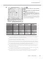
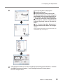
Enter the parameters to "Enable Advanced Settings)" and "Perforated Cut
Controls."
Referring to the chart on the next page, enter the
values based on the grammage of the media to be
used. (The values are indications.)
"Perforated Cut Controls" is
displayed only when the data
contains "PerfCutContour."
Grammage *1
(Thickness)
Cutting Passes *2
Speed *3
Pressure *4
Offset *5
Normal Pressure
Length *6
Perforation Length
*7
Perforation Pressure
*8
210 g/m²
(0.25 mm)
3 times
30 cm/sec
Max. 60 gf
0.5 mm
230 g/m²
(0.30 mm)
3 times
30 cm/sec
Max. 70 gf
0.5 mm
270 g/m²
(0.35 mm)
3 times
30 cm/sec
Max. 80 gf
0.5 mm
310 g/m²
(0.41 mm)
3 times
30 cm/sec
Max. 100 gf
0.5 mm
0.1 mm
0.1 mm
0.1 mm
0.1 mm
20 mm
20 mm
20 mm
20 mm
Max. 60 gf
Max. 70 gf
Max. 80 gf
Max. 100 gf
*1
This is a unit to show the paper thickness. The thickness may be presented in other units.
*2
This is a cutting frequency in the perforated cutting part. Please increase the frequency when the
clipping is not made enough. Smaller values for "Pressure" and "Die-Cut Pressure" and a bigger
value for "Cutting Frequency" can make the better cutout.
*3
This is the moving speed of the cutter. The values in the chart are recommended. If you make the
operation too fast, you cannot make good cutouts.
*4
The force set here is the blade force for the half-cut part. Be sure that the value in the chart is the
upper limit. Exceeding this limit may result in cutting off the object or damaging the cutter blade.
*5
You can set the correction amount of the cutter blade edge here. Enter the offset value written on
the cutter. (The offset value for the included cutter for the perforation is 0.5mm.)
*6
You can set the length of the part "to be left uncut (half-cut) here. The smaller value you use, the
more easily the object can be cut out. If you want to keep the strength on the half-cut part, set
here to make the length longer.
*7
This indicates the part "to be cut out (die-cut)." With the longer die-cut length and the shorter halfcut length, you can make the object which can be cut out more easily.
*8
This is the cutter pressure to the die-cut part. Note that the value in the chart is the upper limit.
Exceeding this limit may result in difficulties in cutting out or damages of the cutter blade.
Chapter 1 Getting Ready
9
1-3 Printer Preparations
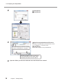
Click
.
The cutting test starts.
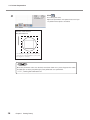
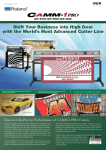
Adjust the parameters and repeat the test until you
can perform the output as intended.
Results of the tests on
the perforated cut
The dotted line region shown above is
cut in the line of perforation. (The solid
line region is cut out.)
Once the parameter values are decided, write them down on a piece of paper. The values
decided here are to be used when the actual perforated cut is performed.
P. 21, "Starting the Perforated Cut"
10
Chapter 1 Getting Ready
1-4 Preparing the Output Data
Concept of Output Data Creation
To perform the fold line and perforated cut operations, you can create the output data by assigning the spot
colors with the following names to the respective lines to be processed.
Fold line: CutContour
Perforated Cut: PerfCutContour
By outputting these data through VersaWorks, the fold line or the perforated cut can be performed.
P. 19, "Chapter 2 Output"
Creating Data for Printing
"The program used to create the printing data is Adobe Illustrator CS4. For detailed information on drawing
methods and how to work with palettes, refer to the documentation or online help for Adobe Illustrator
CS4. If you're using another version of Adobe Illustrator, operations may be somewhat different from those
explained here."
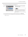
1.
Open the exclusive swatch library
Set the VersaWorks installation DVD in the DVD-ROM drive of your computer.
If any windows for installation, such as "Choose Setup Language," are displayed, click
windows.
to close the
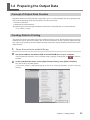
At the swatch palette menu, select [Open Swatch Library], then [Other Libraries].
The "Select Library" window appears.
* The swatch palette is displayed by going to the menu, selecting [Window], and then selecting
[Swatch].
Chapter 1 Getting Ready
11
1-4 Preparing the Output Data
Open the folder in order of "DVD-ROM Drive (D)*," "Tools," "Perforated_Cut_File,"
and "Illustrator," and select "Roland VersaWorks."
Depending on the settings of your computer, the extension ".ai" might not be shown.
* This is the drive where the VersaWorks installation DVD is set in the procedure
.
Click [Open].
The swatch library containing "CutCountour" and "PerfCutContour" opens.
By saving the ".ai" file selected in step
into the folder below, you can register each swatch library
to the Adobe Illustrator's library.
C:\Program Files\Adobe\Adobe Illustrator CS4\Preset\Swatch
(("C" is the name of your computer's local disk.)
Once the registration is performed, you can open the library directly from the swatch palette menu,
eliminating the need to search the file every time you start Adobe Illustrator.
2.
Creating Layers for Printing
Preparing the illustration for printing.
Be sure to draw the illustration in the CMYK mode.
Click "Options for Layer 1" from the layer
pallet menu.
* The layer palette is displayed by going to the menu,
selecting [Window], and then selecting [Layer].
Enter a "Name" in the "Layer Option"
window.
Enter "Print" here, for example. It is recommended
to use a name easily understood as for layer for
printing.
Click [OK].
12
Chapter 1 Getting Ready
1-4 Preparing the Output Data
3.
Creating the layer for the fold line
Click "New Layer" from the layer pallet
menu.
Enter a "Name" in the "Layer Option"
window.
Enter "CutContour" here, for example. It is recommended to use a name easily understood as the
layer for the fold line.
Click [OK].
4.
Create the line for fold line
Assign the spot color, "CutContour," to
the created line.
Creating the layer for the perforated cut
Click [New Layer] from the layer pallet
menu.
Enter a "Name" in the "Layer Option"
window.
Enter "PerfCutContour" here, for example. It is recommended to use a name easily understood as for the
layer for the perforated cut.
Click [OK].
Create the line for the perforated cut.
Assign the spot color, "PerfCutContour,"
to the created line.
Chapter 1 Getting Ready
13
1-4 Preparing the Output Data
5.
Creating the PS file for the fold line
Hide only the layers for the perforated cut
from the layer pallet.
The status is on "Display" if
appears when you click here.
Select [Print] from the [File] menu.
Select [Roland VW].
When a nickname is set, or when more than one
printer is connected, select “Roland VW_(the nickname of the printer used for output).”
Click [Setup].
Click [Continue].
14
Chapter 1 Getting Ready
1-4 Preparing the Output Data
Turn on the [Print to file] option.
Click [Preferences].
Click [Advanced] in the [Layout] tab.
For Windows 2000: In the "Print" dialog box
(the window at the very top of this page), go
to the "Layout" tab and click [Advanced].
Click the down arrow to the right of the
[Paper Size] box, and then click [PostScript
Custom Page Size] from the list that appears."
For "Custom Page Size Dimensions,"
enter the values in the "Width" and "Height"
"fields."
"Enter values for the same size as the illustration you
created from step 2. to step 4.."
Click [OK] three times to close the "PostScript Custom Page Size Definition," "Roland
VersaWorks Advanced Options," and "Printing Preferences" dialog boxes.
The "Print" dialog box returns.
Chapter 1 Getting Ready
15
1-4 Preparing the Output Data
Click [Print].
Click [Print].
Specify the destination and file name.
"Example: "" C:¥CREASING "" for the folder to save to,
and "" CREASE.ps "" as the file name."
"Select the folder you created in ""Creating
a Folder for Saving PS Files"" on page 6."
Click [Save].
The PS file is created in the specified folder.
Provide an arbitrary name for the file. It
is recommended to use a name easily
understood as the file for the fold line.
16
Open the folder you saved to and make sure the file has been created.
Chapter 1 Getting Ready
1-4 Preparing the Output Data
6.
Creating the PS file for the perforated cut
Display only the layers for the perforated
cut on the layer pallet.
When saving the data in the EPS file, be sure to
display the layers for printing and those for the perforated cut. If the layer for printing is not displayed,
the position where the perforated cut is performed
will be misaligned.
Save the PS file in the same way as shown in the procedure
5. from to .
For the file to be saved, it is recommended to use a name easily understood as one for the perforated
cut.
Example: "PerfCut.ps"
Chapter 1 Getting Ready
17
18
Chapter 2
Output
2-1 Starting Output.......................................................................20
Starting the Fold Line.................................................................20
Starting the Perforated Cut.........................................................21
19
2-1 Starting Output
Starting the Fold Line
Be sure to perform the output operation for "Fold Line" first and then for "Perforated Cut."
In performing both operations of the fold line and the perforated cut, be sure to perform the fold line
first. If the perforated cut is done first, it may result in misalignment as it causes difficulties in fixing the
position of the media when the fold line is performed.
Procedure
Confirm that all the preparation for VersaWorks, the printer, and the output data have
been complete.
P. 3, "Chapter 1 Getting Ready"
Replace the cutter with the crease tool.
Load media into the printer.
For the exchange procedures, refer to the User's Manual of your machine.
Be sure to use the same media as one used for the various settings, adjustments, and test printing in the
section of P. 7, "Printer Preparations)."
P. 7, "Printer Preparations"
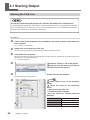
Click the "Queue A" tab of the job list.
Drag and drop the data for the fold line
on the job list for the queue A.
Double-click the job dropped.
The "Job Setting" window appears.
20
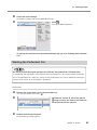
Click
.
Select "Print & Cut" in the operation
mode.
Check the boxes of the following
items.
Return to Origin After Cut
Enable Advanced Settings
Enter the values for "Enable Advanced
Settings."
Chapter 2 Output
Cut Passes
2 times
Speed
1 cm/sec
Pressure
300 gf
Offset
0.000 mm
2-1 Starting Output
Check the other settings.
For the other settings, refer to VersaWorks Online Help.
Click
.
Starting the Output Operation
To perform the perforated cut operation subsequently, go on to "Starting the Perforated
Cut."
Starting the Perforated Cut
Be sure to perform the output operation for "Fold Line" first and then for "Perforated Cut."
In performing both operations of the fold line and the perforated cut, be sure to perform the fold line
first. If the perforated cut is done first, it may result in misalignment as it causes difficulties in fixing the
position of the media when the fold line is performed.
Procedure
Replace the cutter with one for the perforated cut.
P. 7, "Printer Preparations" Procedure
Click the "Queue B" tab of the job list.
Drag and drop the data for the fold line
on the job list for the queue B.
Double-click the job dropped.
The "Job Setting" window appears.
Chapter 2 Output
21
2-1 Starting Output
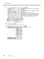
Click
.
Select "Cut Only" for the operation
mode.
Check the box of "Enable Advanced
Settings."
Uncheck the boxes for the other items.
Enter the values decided at the cutting
test for the parameters of "Enable Advanced
Settings" and "Perforated Cut Controls."
P. 8, "Cutting Test Method (Perforated Cut)"
"Perforated Cut Controls"
is displayed only when
the data contains "PerfCutContour."
Check the other settings.
For the other settings, refer to VersaWorks Online Help.
22
Click
.
The output operation starts.
Chapter 2 Output
Chapter 3
Maintenance/FAQ
3-1 Maintenance..........................................................................24
Daily Maintenance......................................................................24
Maintenance of Crease Tool.......................................................24
3-2 What to Do If (FAQ)..............................................................25
What to Do If…...........................................................................25
23
3-1 Maintenance
Daily Maintenance
The perforated cut operation is likely to generate paper dust, and the diligent cleaning is recommended. For the
cleaning method, refer to the descriptions regarding "Maintenance" of the User's Guide for your machine.
The cutter is likely to get exhausted faster in the perforated cut operation due to the deeper cutting process.
The strain on the cutter protection is also heavier. Be sure to perform the maintenance periodically.
Maintenance of Crease Tool
The tip of the crease tool may get attached with dust and the like. Wipe the tool gently with a cloth wrung
out well of water-down mild detergent.
When the ball part on the tip gets out of rotation, the tool comes to the end of its usefulness. To purchase
another one, contact your authorized Roland DG Corp. dealer or us.
24
Chapter 3 Maintenance/FAQ
3-2 What to Do If (FAQ)
What to Do If…
During the perforated cut operation, sufficient cutout cannot be performed.
Adjust the cutting-in amount of the cutter for the perforated cut. "Media thickness + 0.2mm" is the upper
limit for the cutting-in amount. When the cutting-in amount is adjusted, increase the cutting frequency, and
perform the cutting tests.
P. 8, "Cutting Test Method (Perforated Cut)"
If you cannot perform the sufficient cutout despite the process above, the problem may be due to exhaustion
of the cutter. Contact your authorized Roland DG Corp. dealer or us for your machine.
Cutting is performed on the area you want to leave without cutting out in performing
the perforated cut.
Adjust the cutting-in amount of the cutter for the perforated cut. "Media thickness + 0.2mm" is the upper
limit of the cutting-in amount. When the cutting-in amount is adjusted, perform the cutting tests applying
the adjustments below.
Make the parameter value for "Normal Pressure Length (the length of the region to be left without cutting
out)" larger.
Lower the parameter value for "Pressure (the blade force on the half-cut region or the legion to be left
without cutting out)" by 5g.
The print line and the fold line or the perforated cut line are misaligned.
Have the adjustments and tests for the machine unit been done?
Before performing the fold line and the perforated cut operation, conduct the adjustments and tests for the machine unit. To perform the perforated cut operation, be sure to conduct the test for the perforated cutting.
P. 7, "Printer Preparations," p. 8, "Cutting Test Method (Perforated Cut)"
Are you using the middle pinch roller?
Without the middle pinch roller, the media transfer may be unstable. For the method to use the middle pinch
roller, refer to the User's Manual for your machine.
Is the media rolled back or strained?
If the media is rolled back or strained, the media transfer may become unstable to result in misalignment
between the print line and the fold line or the perforated cut line.
When the humidity is high, the paper board is likely to get rolled back or strained.
The offset values for the cutter is correctly set up?
For the fold line, set the offset value at "0," and for the perforated cut, enter the offset value for your cutter.
(The offset value for the included cutter for the perforated cut is 0.5mm.)
P. 9, "Cutting Test Method (Perforated Cut," Procedure
, P. 20, "Starting Fold Line," Procedure
* The position accuracy and the repetition accuracy for printing and cutting depend on the specifications
of your printer.
For the perforated cut, you want to adjust the length of "the region to be cut out" and
"the region to be left without cutting out."
Adjust "Perforated Length (the length of the region to be cut out)" and "Normal Pressure Length (the length
of the region to be left without cutting out)."
P. 9, "Cutting Test Method (Perforated Cut," Procedure
Chapter 3 Maintenance/FAQ
25
3-2 What to Do If (FAQ)
You want to make the fold line with the perforated cutting line.
By applying the dotted cut, you can make the fold line with the perforated cut. Make the following settings
with VersaWorks.
Make the settings of "Normal Pressure Length (the length of the region to be left without cutting out) and
"Perforated Length (the length of the region to be cut out)" at the same value. (about 3 to 5 mm)
Make the setting of the pressure at the low level. (Minimum: 30gf )
Note the following points when performing the above output operation as using the normal perforated
cut.
Make the separate data from the data for the normal perforated cut.
Output the data for the above process before the data for the normal perforated cut.
26
Chapter 3 Maintenance/FAQ
Chapter 3 Maintenance/FAQ
27
28