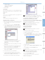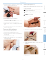
1
SimMom
™
Directions for Use
www.laerdal.com
www.limbsandthings.com
Table of Contents
Cautions and Warnings 4
Specifications 45
Introduction
Spare Parts and Accessories 47
6
–– SimMom Overview
6
–– Items Included
6
–– Features
8
Setup
10
–– Attaching Manikin Legs10
–– Gown Features10
–– Configuring System
10
Software 12
–– User Interface
12
–– Changing SimMom Settings During Simulation
15
–– Changing Default Setting
15
–– Fetal Monitoring16
–– Patient Monitor
18
–– Laerdal Debrief Viewer20
–– Customizing Scenarios
20
–– Using Handler Editor to Link Actions
21
–– Laerdal Advanced Video System (AVS)
21
–– Software Reinstallation21
Performing Simulations22
––
––
––
––
––
––
––
––
––
––
––
––
––
––
––
Airway Management 22
Setting Up ECG Snaps/Defibrillation Connectors 22
Connecting Blood Pressure Cuff 22
Preparing IV Simulations
23
Birthing Positions
23
Preparing Baby for Delivery 23
Delivery Techniques 24
Deliveries 25
Pelvic Components25
Modular Components26
Catheter Installation30
Filling Blood and Urine Reservoirs
31
Cleaning Blood and Urine Reservoirs
32
Performing Hybrid Simulations
32
Using the Bed Strap 32
Maintenance33
––
––
––
––
––
––
––
––
––
––
––
––
––
––
––
––
Pupil Replacement
33
Eyelash Replacement33
Wig Care and Upkeep
33
Neck Collar/Cricothyroid Replacement
34
Arm Replacement34
Pneumothorax Bladder Replacement 36
Thoracentesis Module Replacement
37
Abdominal Skin Replacement
37
Perineum/Birth Canal Skin Replacement
38
Cervix Replacement39
Pelvic Floor Replacement40
Urine Reservoir Replacement
40
Blood Reservoir Replacement
41
Pelvis Replacement 41
Replacing Baby Limbs43
VitalSim Battery Replacement
43
3
Cautions and Warnings
Regulatory Information
–– Use only Laerdal Airway Lubricant for airway lubrication, and
apply liberally.
This device complies with Part 15 of the FCC Rules. Operation is
subject to the following two conditions:
–– Use only SimMom & PROMPT Birthing Lubricant (Laerdal
Catalogue No. 377-18850) to lubricate baby, cervix, birth canal,
and modules. Do not use any other lubricant. Do not use
PROMPT Birthing Lubricant (Laerdal Catalogue No. 376-02950,
Limbs & Things No. 50181) or SimMom Birthing Lubricant
(Laerdal Catalogue No. 377-14450, Limbs & Things No. 10191).
Non-approved lubricants can damage the system.
1. This device may not cause harmful interference.
2. This device must accept any interference received, including
interference that may cause undesired operation.
Caution
Warning: SimMom & PROMPT Birthing Lubricant is not for
personal use.
Changes or modifications not expressly approved by the party
responsible for compliance could void the user’s authority to operate
the equipment.
The product is in compliance with the essential requirements
of Council Directive 2004/108/EC on electromagnetic
compatibility (EMC).
The product is in compliance with Council Directive 2011/65/
EU on restriction of the use of certain hazardous substances
(RoHS).
–– Rinse, clean, and dry manikin component modules.
Dispose of in accordance with local requirements and
regulations.
–– Fold the torso skin back and powder the inside of the torso skin
to decrease friction. Do not spill powder into manikin chest cavity.
–– Do not attempt to perform the following techniques on this
manikin due to the inability to properly sanitize the airway:
Disclaimer
–– Mouth-to-mouth/mouth-to-mask ventilation
Use of the SimMom patient simulation system to train personnel
should be undertaken under supervision of suitably trained technical
or medical personnel with an understanding of educational principles
as well as recognized medical protocols. As with all manikins or other
such training devices, there may be approximations, variations and
inaccuracies in anatomical features and the physiological modeling.
This being the case, Laerdal does not guarantee that all features are
completely accurate.
–– Insertion of simulated vomit or fluids for suctioning
Environment
In cold conditions, wait until the manikin has reached room
temperature before starting up the manikin.
To avoid overheating and reduce wear:
− When using in temperatures above 40°C (104°F), always allow
the manikin to cool down between training sessions.
Global Warranty
− When using in a bed, manikin should not be covered with heavy
bedding that prevents heat transfer from the manikin.
See the Laerdal Global Warranty Booklet or see www.laerdal.com.
Country of origin - SimMom is made in USA.
General Manikin Handling
Laerdal Medical
Take the following precautions to avoid personal injury or damage to
the product:
P.O. Box 38
226 FM 116
Gatesville, Texas 76528, USA
–– Introduce fluids into the manikin only as directed in this document.
Failure to do so may result in damage to the manikin and its
components.
General Care
− Lubricate the oral and nasal airways with the lubricant provided
prior to inserting any instrument, tube, or airway device. Also,
lubricate instruments and tubes prior to use.
To maintain manikin skins, wash hands before use and place the
manikin on a clean surface. Laerdal recommends the following:
–– Use gloves during simulation scenarios. Avoid using colored
plastic gloves, as they may cause discoloration of the manikin skin.
− Lubricate cervix, birth canal, and baby before each delivery.
–– Do not use felt-tipped markers, ink pens, acetone, iodine, or
other staining medications near the manikin. Take care not to
place the manikin on newsprint or colored paper. Staining may
be permanent.
− Do not introduce humidified air into the system during ventilation.
–– Clean manikin skins with mild soap and water.
–– Never use the SimMom manikin outdoors in wet conditions, as
this may pose a shock hazard or damage the manikin.
− Do not use the manikin if the internal tubing and cabling is
disconnected.
–– If a training session involves the use of fluids in the IV arm or
blood and urine bags, drain the arm immediately following the
training session.
Warning: Do not use automated external chest
compression machines on the manikin.
4
Mechanical or Electrical Hazards
Caution Latex: This product contains Natural Rubber
latex, which may cause allergic reactions when in contact with
humans.
Do not use the SimMom manikin if:
− Internal or external cables, tubes or connectors are damaged.
− There is fluid leakage in or on the manikin.
− There are unusual sounds indicating air leakage or mechanical
damage.
–– Read and follow all safety and operating instructions provided
with your defibrillator and associated equipment and within your
defibrillator’s original user manual.
− There are signs of electrical malfunction, such as an
unresponsive manikin or unusual smell or smoke.
–– Follow defibrillation protocol by avoiding contact between
the external paddles and any of the electrode sites while
defibrillating.
Warning: Avoid pinch hazards - Do not use the manikin
without the external skins.
–– Failure to follow safety measures could result in injury or death.
Storage and Transportation
–– When performing defibrillation, use the defibrillator connectors
or the zap plate mounted on the manikin’s chest. Do not use
the ECG connectors, which are designed exclusively for ECG
monitoring. Defibrillation on the ECG connectors will damage
the internal electronics of the manikin and may cause personal
injury.
Manikin Setup
–– T
he SimMom manikin and accessories are heavy when packed in
boxes or combined in optional carrying cases. Always ensure that
SimMom is firmly secured during transportation and storage to
prevent personal injury or damage to the product.
Advanced System
− Skins are torn or not properly fastened.
A conventional defibrillator may be used on SimMom. During
defibrillation, the defibrillator and manikin may present a shock hazard.
When using a defibrillator on the manikin, take the following safety
precautions:
Standard System
− Limbs are not attached to the torso.
Defibrillation Hazards
–– Do not defibrillate the manikin when it is turned OFF or if it is not
functioning normally.
–– Do not perform defibrillation when manikin is resting on a wet
surface.
Maintenance
–– The manikin torso must always be kept dry. Sudden changes in
temperature may result in condensation collecting on electronic
components, which could pose a shock hazard. Allow the manikin
to acclimate before defibrillating.
− Using a defibrillator in temperatures over 35° C (95° F) may
cause manikin to overheat.
− Do not provide more than 2 x 360J defibrillator discharges
per minute.. After 30 minutes, cease all shocking for at least 15
minutes before starting a new sequence.
Troubleshooting
–– The manikin must not come into contact with electrically
conductive surfaces or objects during defibrillation.
–– Avoid use in all flammable environments. For example, high levels
of pure oxygen should be avoided during defibrillation. Ensure
good ventilation if concentrated oxygen is used near the manikin.
–– To prevent torso skin electrode pitting, do not apply conductive
gel or conductive defibrillation pads intended for patient use.
Do not defibrillate the manikin if the torso skin is not in place.
5
Spare Parts
Specifications
–– Pressing down too hard on the defibrillation connectors during
defibrillation may also cause arcing and pitting.
––
Overview
Cautions and Warnings
Introduction
SimMom Overview
Items Included
SimMom has been developed in partnership by Limbs & Things and
Laerdal, combining the best that both companies have to offer in
healthcare simulation products. By integrating the strengths of the
PROMPT Birthing Simulator and the ALS Simulator, SimMom provides
the user with both anatomical accuracy and authentic simulation
experiences that together, facilitate valuable learning experiences for a
wide range of midwifery and obstetric skills.
–– Manikin
SimMom responds to clinical intervention, instructor control, and
pre-programmed scenarios, and allows for the observation of both
maternal and fetal vital signs. Instructors can articulate mother
and baby in multiple positions in order to simulate various types
of deliveries. Students can practice diagnosis and treatment of the
mother and fetus.
–– USB Webcam
SimMom can be used to teach skills such as airway management, CPR,
heart and lung sound auscultation, and blood pressure auscultation.
SimMom can also simulate the following delivery scenarios:
Accessories
–– Modules
–– Baby
–– Compressor
–– Laptop
–– USB Hub
–– VitalSim Control Unit
–– Patient Monitor (in applicable versions only)
–– BP Cuff
–– Thoracentesis Pads
–– Normal delivery
–– Maternal collapse
–– Eye Kit
–– Skin Collars
–– Breech presentation
–– Hardware Kit
–– Directions For Use (DFU)
–– IV Fluid Collection Bags
–– DVD Video Guidelines
–– Forceps
–– Postpartum
Hemorrhage
(PPH), including atonic/
boggy uterus and retained
placenta/placental fragment
–– Lubricant
–– Wig
–– Vacuum
–– Sepsis
–– Crycothyroid
Membrane Tape
–– Blood Concentrate
–– Assisted deliveries
–– Shoulder dystocia
–– Uterine inversion
–– Cord prolapse
–– Ruptured uterus
–– Pneumothorax
Bladder Repair Kit
–– Eclampsia & pre-eclampsia
–– Blood and Urine Reservoirs
6
–– Cuttable Umbilical Cords
–– Normal and C-Section Skins
–– Cervix
Right Arm ECG
Lead
Sternum Defib Plate
Intramuscular Injection Site
Left Arm ECG
Lead
Intramuscular Injection Site
IV Fluid Connection
Setup
Introduction
Introduction
Left Leg ECG Lead
BP Cuff Connection
Right Leg ECG
Lead
Apex Defib Plate
Software
IV Fluid Connection
Blood Pressure Arm
Intramuscular Injection Site
Intramuscular Injection Site
BP Tubing
Specifications
External Air Connection
Maintenance
IV Access
Performing
Simulations
IV Access
Spare Parts
37 Pin Serial Cable
(Manikin to VitalSim Cable)
7
Introduction
Features
–– Realistic vulva and anus for digital exams
Movement
–– Realistic "at term" abdominal skin
–– Pre-incised C-section skin
–– Seizure indicator
–– Fluids (e.g. blood, stained amniotic fluid and urine)
–– Able to position at all fours:
–– Urine catheterization/instillation
–– Realistic rotation of the shoulder and hip joints
–– Pelvic floor
–– Legs bend at the knees
–– Birth canal
–– Arms bend at the elbow
–– Manikin positions:
Breathing Features
1. Supine
4. Left lateral
–– Simulated spontaneous breathing
2. Semi-recumbent
5. Legs in stirrups
–– Variable respiratory rates (0-60 bpm)
3. All fours
6. McRoberts
–– Bilateral and unilateral chest rise and fall
–– Normal and abnormal lung sounds
Airway Features
–– 4 anterior auscultation sites
–– Obstructed airway
–– Bilateral midaxillary sites
–– Tongue edema
–– Tension pneumothorax
–– Right lung, left lung and bilateral lung blockage
–– Oxygen saturation waveform
–– Head tilt/Chin lift
Cardiac Features
–– Jaw thrust
–– Extensive ECG library
–– Suctioning techniques
–– Normal and Abnormal Heart sounds synchronized with ECG
–– Bag-valve-mask ventilation
–– ECG rhythm monitoring
–– Oropharyngeal and nasopharyngeal airway insertion
–– 12 lead ECG display
–– Combitube, LMA and other airway device placement
–– Defibrillation and cardioversion
–– Endotracheal intubation (ET)
–– Responds to external pacing with settable pacing threshold (20200 mA)
–– Nasotracheal intubation
–– Digital intubation
–– Retrograde intubation
Circulation Features
–– Nasal and oral fiberoptic intubation
–– BP measured manually by auscultation of Korotkoff sounds
–– Trans-tracheal jet ventilation
–– Bilateral carotid pulse, brachial and radial pulses (right side only)
synchronized with ECG
–– Right mainstem intubation
–– Pulse strength variable with BP
–– Surgical and needle cricothyrotomy
–– Pulse palpation is detected & logged
–– Chest tube insertion
–– Cricoid pressure
Chest Compressions
–– Needle decompression
–– CPR compressions generate palpable pulses, blood pressure wave
form, and ECG artifacts
Pelvic Components
–– Detection and logging of a series of compressions.
–– Interchangeable uterus modules
Other Features
–– PPH uterus with tonic and atonic states and with retained
placenta and placental fragment
–– Normal and abnormal bowel sounds and fetal heart sounds (not
at the same time)
–– Uterine inversion
–– Interchangeable pupils (normal, dialated, and constricted)
–– Amniotic bag for intrapartum fluids
–– Patient Voice
–– Bony Pelvis with landmarks
–– Pre-recorded sounds
–– Cervix that dilates from 4 cm to full
–– Custom sounds
8
–– Instructor can simulate patient’s voice
Press again to turn the unit off. The indicator is steady green if the
base unit has contact with the manikin. If there is no contact with
the manikin, the indicator will blink green. If the battery needs
replacement, the indicator will blink, alternating between green
and orange.
Vascular Access
–– Pre-ported IV access (bilateral)
–– Subcutaneous and intramuscular injection sites
B. DC Power supply input: Used for stationary training and to limit
battery consumption.
Birthing Baby
Introduction
Introduction
C. Manikin connector: Connects the base unit to the manikin.
–– Realistically modeled head with all head landmarks present
(fontanelles and sutures)
E. USB port: For connection to PC.
–– Head can be easily manipulated by “puppeteer” and flexes
naturally as it is pushed through the birth canal
G. Blood pressure connector: Connects to the blood pressure tube
exiting lower right side of manikin.
–– Mouth for suction and Smellie-Veit (if required)
H. Battery pack: Holds 6 replaceable C-cell batteries.
–– The birthing baby’s body is designed to allow it to be easily pushed
through the birth canal
Patient Monitor
–– Bony prominences of the hips to support Lovsett’s maneuvers
The optional Patient Monitor has a configurable touch-display. It
simulates a real patient monitor as found in hospitals and ambulances.
F. Remote connector: Not applicable to SimMom.
–– Realistically positioned landmarks - scapulae and clavicles
–– The Patient Monitor Displays patient’s clinical status, including a
maximum of 5 waves and 14 parameters.
–– Arms and legs allow full articulation for all maneuvers required
during deliveries - particularly breech and shoulder dystocia
Software
–– Head designed and tested so it can be used for forceps deliveries
(rotational and normal) and vacuum delivery (kiwi and ventouse)
Setup
D. Microphone input: External microphone attachment.
Electronic Fetal Monitoring - EFM/Cardiotocography - CTG
–– Electronic fetal monitoring on the Patient Monitor Interface
displays the fetal heart rate and uterine activity parameters.
–– EFM graphic display: fetal heart rate waveform and uterine activity
waveform.
Software
–– EFM is displayed on the patient monitor with mother’s vital signs.
The Graphical User Interface (GUI) controls scenario and manikin
function via the Instructor PC, enabling the instructor to easily operate
and adjust mother and fetus vital signs. The GUI is highly configurable
and capable of running on-the-fly, customized, or preprogrammed
scenarios.
–– Fetal monitoring is recorded and it is possible to scroll back to
view on the patient monitor.
–– The software allows the instructor to use the preset states as well
as utilize the customized parameters.
The electronic fetal monitoring (EFM) display on the GUI shows
the Fetal Heart Rate and Uterine Activity waveforms alongside the
mother’s vital signs. The software records at least ninety minutes of
fetal monitoring, which can be viewed by scrolling back on the patient
monitor. The instructor can use the preset states as well as utilize the
customized parameters.
VitalSim Control Unit
The VitalSim control unit serves as the interface between the PC and
the manikin. VitalSim connects to the PC through the USB, powers
and controls the manikin, and provides feedback from the manikin
back to the PC.
Web Downloads
Spare Parts
Visit http://www.laerdal.com to download the latest Directions for
Use and SimMom Software.
Maintenance
–– Video capture from the Patient Monitor display and the webcamera can be stored for use in the Debrief Viewer.
Specifications
–– Fetal heart rate: normal, bradycardia and tachycardia (via software)
Performing
Simulations
–– Users can request radiology and lab reports from the instructor
via the Patient Monitor software.
–– Umbilicus and placenta (normal and retained)
A. On/Off button and indicator: Press once to turn the unit on.
9
Setup
Setting Up Your Manikin
2. Tighten the adjustment screw using the 8mm Allen key wrench
until the desired tension on the hip is reached. Do not over
tighten the adjustment screw because this may damage the jaws
Before SimMom is ready to run simulations, the manikin, birthing baby,
and computer system must be setup correctly. This section covers
the following:
Note: Legs can be removed by loosening the adjustment
screw and pulling them free of the hip ball.
–– Connecting Belly Skin Audio Cable
–– Attaching Manikin Legs
–– Gown Features
Gown Features
–– Configuring System PC, Patient Monitor, and Webcam
The SimMom gown has two flaps that provide access to the abdomen
during birthing simulations. The gown also has holes through which
the manikin’s wires can pass.
Connecting Belly Skin Audio Cable
To connect the SimMom belly skin audio cable:
1. Unhook the belly skin from the three attachment sites on either
side of the pelvis and fold the skin over towards the feet.
2. Remove the C-Section Belly skin shipped inside the pelvis and
Abdominal Access
Flap
store with your other SimMom accessories.
3. Connect the black audio cable on the under side of the belly skin
Abdominal Access
Flap
Wire Exit
to the audio port located on the right side of the pelvis
Configuring System
The Instructor PC controls the simulator. It includes software
programs for creating and editing scenarios, as well as an application
for debriefing simulation sessions with video capture from a web
camera and the patient monitor.
4. Reattach belly skin.
The Patient Monitor can be configured to replicate most patient
monitors. It also doubles as a display for other functions, such as
12-lead ECG, X-ray images, and lab results to view the patient’s case
history.
Attaching Manikin Legs
Manikin legs allow full articulation and bend at the knee. They can
simulate maneuvers performed during various deliveries.
The Web Camera records video and sound of the simulation for use
during the debriefing session.
To attach the manikin leg:
1.
Setup Summary
Grip the thigh and gently push the hip clamp jaws onto the hip
1. Start the Instructor PC
–– Connect the mouse and power supply to the computer and
power ON.
ball on the pelvis.
Note: If the jaws must be opened further to fit on the hip ball,
turn the adjustment screw using the 8mm Allen key wrench.
–– Make sure that the SimMom simulator icon is displayed on the
Instructor PC desktop.
2. Install the USB hub
–– Connect Power to the USB hub.
–– Connect USB hub to Instructor PC.
3. Connect the Patient Monitor Cables
–– Put aside the software CD that comes with the monitor. DO
NOT INSTALL software CD.
–– Route the cables through the Patient Monitor stand and connect
10
Setup
Introduction
Setup
touch each target as it changes position and follow the arrow
with your finger.
–– When the ELO Touchscreen dialog box appears, touch the green
“check box” button.
–– Click <OK>.
–– Connect power cable to a wall outlet and power ON the Patient
Monitor.
Software
them to the corresponding outlets located at the bottom of the
screen.
-- Video cable
-- USB cable
-- Audio cable (blue mini jack with single wire)
-- Power cable
-- Secure the cables using the strain reliefs.
8. Connect the USB Camera to the USB hub.
–– Connect the audio cable (white mini jack with single wire)
to the VitalSim Control Unit.
5. Set Up the Instructor PC for Extended Desktop Display to
Support the Patient Monitor.
–– Connect the power cable to the Control Unit and power
source.
–– Right click on the instructor PC desktop
10. Connect the Manikin to the VitalSim Control Unit.
–– In the drop down menu select <Screen Resolution>
–– In the <Multiple Displays> option, select <Extend these
displays>.
–– Connect the grey 37-Pin Serial Cable and clear tubing exiting the
manikin’s middle right side to the back of the VitalSim control
unit.
–– Click <Apply> and then <Keep these Settings>.
–– Place the Blood Pressure cuff on the right arm of the manikin.
–– The Instructor PC (display 1) should have a resolution of 1600
x 900.
–– Attach the clear tubing exiting the upper right side of the torso
to the clear tubing on the Blood Pressure cuff.
–– The Patient Monitor (display 2) should have a resolution of 1280
x 1024.
–– Power on the VitalSim Control Unit.
–– Click <OK>.
11. Install the Compressor.
6. Connect the Patient Monitor to the USB Hub.
–– Unpack the compressor with the power cable.
7. Calibrate the Touchscreen Patient Monitor.
–– Connect the power cable to the compressor and wall outlet.
–– Unpack the compressor air tube and connect it between the
manikin and the compressor.
–– Double-click on the Elo logo in the system tray in the right corner
of the screen.
–– Power on the compressor.
–– Click the <Align> button on the dialog box that appears.
–– Operate the unit according the accompanying instructions.
–– If target indicators first appear on the Instructor PC screen, press
<Esc>, or wait until they appear on the Patient Monitor.
The simulation system is now ready to use.
–– When the target indicator appears on the Patient Monitor,
11
Maintenance
IMPORTANT: Do NOT connect the USB cable to the PC or
USB Hub yet.
Specifications
–– Connect the USB cable from the VitalSim Control Unit to the
USB hub.
Spare Parts
4. Connect the Patient Monitor video cable and 3-way audio cable
(black mini jack with double wire) to the Instructor PC.
Performing
Simulations
9. Connect the VitalSim Control Unit.
Software
Introduction to SimMom Software
User Interface
The Instructor PC uses the Instructor Application software to manage
simulation scenarios. The instructor can pause a scenario at any time
and run the simulation in manual (on-the-fly) mode, customizing
the patient parameters as needed. SimMom software includes the
following features:
The graphical user interface for SimMom is controlled by the Instructor
PC. It is highly configurable and easy to operate. It controls the
maternal and fetal vital signs, and can utilize custom or prepackaged
scenarios.
Instructor PC Application Screen Overview
–– User Interface
The Instructor PC application screen provides functional areas for
viewing and controlling patient clinical features.
–– Help Files
–– Scenarios
–– Electronic Fetal Monitoring
–– Patient Monitor
–– Debrief Viewer
1. Program Menu Bar
7. Trend and Handler Control
2. Respiratory Control
8. Trend Preview Window
(hidden by default)
3. Difficult Airway Control
9. Event Windows
4. Defibrillation and
10. Electronic Fetal Montoring
Pacing Controls
–– Scenario Customization
Instructor Software License
Instructor PC is shipped from Laerdal Medical with a pre-activated
license installed.
Any changes or updates of the computer hardware (e.g. new hard
drive or mother board) may render the license invalid. Please contact
your local Laerdal support for assistance with re-activating the license.
12
5. Debrief Log
11. Instructor Monitor Control
6. Scenario Control
12. Simulator Controls
Software
–– View and control shocks to conversion and pacing threshold.
–– Select and exchange running and waiting rhythms.
–– Click the <Extrasystole> button to insert an extra systole into
the running rhythm.
Introduction
4. Defibrillation and Pacing Control
5. Debrief Log (Session Log)
–– Shows all activities performed during the simulation.
–– To start, pause, or halt scenarios. This section also contains the
Debrief button, which will stop the session and open the debrief
log in the Debrief viewer.
Setup
6. Scenario Control
7. Trend and Handler Control
–– Trends window displays running trends.
–– Use the <Start/Stop> button to open the Trend and Handler
Control dialogue box and make changes, select Trends or
Handlers, and start or stop both Trends and Handlers.
Performing
Simulations
Description of Functions (refer to image on pg. 12)
Software
–– Trends permit physiological changes over a period of time.
1. Program Menu Bar
–– File includes controls for starting a scenario, turning on and off
monitor sound, importing vocal sounds and media files, adding
media files, and exiting the software.
–– Simulation includes controls for starting, pausing, fast forwarding
simulations, and going to debriefing.
–– Edit includes controls for editing monitor setup, starting editors
(scenario, handler, and trend), configuration (microphone and
video recording), setting vital signs, adjusting Korotkoff controls,
and starting SimMom dialog.
–– Event handlers enable events to trigger simulator responses.
–– Handlers window displays currently running handlers.
Maintenance
–– View can select patient or instructor monitor setup.
–– Help includes help files.
8. Trend Preview Window (hidden by default)
2. Respiratory Control
–– Window displays the simulation control graph, which illustrates
the trend in patient parameters of past, current, and predicted
future trends throughout the simulation.
–– Adjust the simulator’s respiratory rate.
–– Turn chest rise off and on.
Specifications
–– Use the <Hide Trends> button to hide or show the trend
preview window.
–– Calibration calibrates the BP instrument.
3. Difficult Airway Controls
Spare Parts
–– Set ventilation and intubation.
–– Preset controls for:
–– Normal.
–– Cannot intubate, can ventilate.
–– Cannot intubate, cannot ventilate.
13
Software
–– Trend Preview Window is hidden by default. To activate, click
<Show Trends> under the Handlers dialog box. To enable at
start up, go under <Edit> on the program menu bar and click
<configuration>. On the Configuration menu screen, click
<Display parameter Trend Preview Window at startup> and
select <enabled> from the drop down menu.
–– Set boggy uterus and bleeding uterus.
–– Set pulse strength.
–– Pressurize urine bladder.
Editing Monitor Setup
To edit the monitor setup:
1. Click <Edit> in the Program Menu Bar.
2. Select <Edit Monitor Setup...> from the pull down menu.
-
9. Event Windows (3)
To change the waveform or numeric layout, click on one of the panels
to the far left of the screen.
–– Contains checklists of events relevant for the simulation. An Event
is an action (or behavior) exhibited by the user.
To change which waveforms and numeric layouts are displayed:
10. Electronic Fetal Monitoring
1. Click on one of the waveforms or numeric layouts on the large
panel in the middle of the screen.
–– View status of fetal heart rate and uterine activity.
–– To view additional waveform activity, left click and hold the EFM
display and drag to the right. When the fetal monitor scroll speed
is set at 1 cm per minute, the monitor displays 60 minutes of
activity. When the fetal monitor scroll speed is set at 3 cm per
minute, the monitor displays 20 minutes of activity.
2. Scroll over to the Available parameters menu, and select the
desired parameter.
3. Change the waveform or numeric layout by either clicking the
<Select Parameter> button or double clicking on the desired
parameter.
11. Instructor Monitor Control
4. Click <Apply> to apply the changes to the Instructor Monitor
Control on the user interface.
–– View status of mother’s vital signs throughout the simulation.
–– Use the <Fetal Monitor> button to connect or disconnect the
EFM sensor to the Patient Monitor.
5. Click <OK> to exit the Monitor Setup screen.
To return to the default values on a waveform or numeric layout, click
the <Set to Default Values> button.
–– Use the <Toggle Monitor> button to select which vital signs
(patient, EFM, or both) are displayed on the Patient Monitor.
To download a custom layout, click the <Open Setup> button.
–– Adjust patient monitor waveforms and parameters by either
clicking the individual waveform or scrolling over the numeric
parameter readings and using the mouse wheel.
To save a layout, click the <Save Setup> button.
Running a Scenario
12. Simulator Controls
–– Launch the Instructor Application.
–– View and set lungs, heart, bowels, and fetal heart sounds.
–– Click <Start Scenario>. This will open a list of scenarios.
–– Set vocal sounds. (View sound volume by clicking on the speakers
displayed next to the area you want to configure).
–– Select and open.
–– Click <Play> button to start.
–– Set seizure.
Note: <Pause> button changes to <Play> button when the
scenario is paused.
–– Set lung resistance function (on/off).
–– Set pneumothorax.
The <Pause/Play> button is located below the <Start Scenario>
–– Set tongue edema.
14
Software
Default settings for simulations can be changed by accessing the
Adjust Patient Parameters During Simulation
Configuration Menu. To access the Configuration Menu from
Instructor Application screen:
The Patient Monitor shows the patient’s current status. To manually
adjust the patient parameters, click the individual graphs or numeric
parameters. Pop-up menus allow the instructor to change the relevant
parameters. Hold the cursor over a numeric parameter for 1 second,
the selected parameter’s background will turn to grey and the mouse
pointer will change appearance, indicating that the scroll wheel can be
used to increase or decrease the value.
1. Select the <Edit> menu in the Instructor Application.
Introduction
Changing Default Setting
button. When a simulation is running, click this button to pause the
session.
Note: Once the new default settings are saved, the new
parameters will become the start up default for future
simulations.
Stop Simulation Session
When the simulation session is complete, click the Stop button
< > below the <Start Scenario> button.
Setup
2. Select <Configuration> from the drop-down menu.
Debrief Log
Software
The Debrief Log records the patient responses and learner events
that occur during simulation. Events can also be added manually by
the instructor. This information is then made available in debrief files
at the end of the simulation session.
To add a comment to the Debrief Log on user performance, click the
<Add Comment> button.
The following default settings are listed under the SimMom feature
set values heading on the Configuration menu.
Changing SimMom Settings During Simulation
By accessing the SimMom Dialog Menu, you can adjust the Seizure,
Boggy uterus, and Uterus bleeding settings during the simulation. Any
changes made in this window will not effect the default settings of
the manikin.
2.
Select <Start SimMom Dialog> in the drop down menu.
3.
Increase or decrease to desired values.
4.
Click <Apply>.
–– Seizure intensity (75-100)
–– Pneumothorax
pressure (0-6)
–– Uterus pressure (0-6)
Fetal Monitor Scroll Speed
From the Configuration menu:
1. Select the <General> tab in on the Configuration screen.
2. Select the <Fetal monitor scroll speed> option under the Fetal
monitor subheading.
3. Adjust the speed in the drop down menu.
Specifications
In the Instructor Application, click <Edit> in the Program Menu
Bar.
–– Uterus bleeding
flow (60-100)
Spare Parts
1.
–– Tongue edema
pressure (0-6)
Maintenance
Save the Debrief Log to archive and/or review later. Click <Debrief>
to start the Debrief Viewer. For more information, see The Laerdal
Debrief Viewer section of this manual.
Performing
Simulations
Save Files and Laerdal Debrief Viewer
15
Software
Adjust Fetal Heart and Uterine Activity Parameters During
Simulation
Tongue Edema
From the Configuration menu:
To adjust fetal heart parameters and uterine activity parameters, click
the EFM display to open the Fetal simulation setup window.
1. Select the <General> tab on Configuration screen.
2. Click the <Tongue edema pressure> option under the SimMom
feature set values subheading.
Under the Select preset tab, the user can perform the following
functions:
3. Enter the desired pressure rate into the dialog box.
–– Increase or decrease the fetal heart rate baseline by sliding the
toggle left or right.
–– Select preset parameters for baseline variability, fetal heart pattern,
and uterine activity.
Seizure
From the Configuration menu:
1. Select the <General> tab on Configuration screen.
To load a preset parameter into the simulation:
2. Click the <Seizure intensity> option under the SimMom feature
set values subheading.
1. Click on a preset parameter in one of the menus (Baseline
variability, Fetal heart pattern, or Uterine activity).
3. Enter the desired intensity into the dialog box.
Note: The preview screen displays the effects of the
parameter changes on the simulation before they are actually
loaded into the simulation.
Help Files
Software Help-files can be accessed as follows:
2. Click the <Apply> button to load the parameter into the
simulation.
1. Click the Windows <Start> button
2. Select <Programs>.
Under the Custom tab, the user can customize the simulation by
manually adjusting certain parameters using the sliding toggle.
3. Select <SimMom Instructor Applications>.
4. Select the <SimMom Help File>.
Fetal Monitoring
The electronic fetal monitor (EFM) on the user interface displays the
Fetal Heart Rate and Uterine Activity waveforms. The EFM has the
option to scroll at 1 cm or 3 cm per minute. At 1 cm per minute, the
EFM shows 60 minutes of fetal monitoring without having to scroll.
At 3 cm per minutes, it shows 20 minutes without having to scroll. It
records at least 90 minutes of fetal monitoring that can be viewed by
scrolling back.
To scroll back, left click and hold on the EFM display and then move
the mouse to the right.
Baseline fetal heart rate parameter controls the rate of the fetal heart.
Fetal heart pattern parameters include the following:
–– FHR (fetal heart rate) offset sets FHR relative to baseline.
–– Acceleration slider sets amplitude of periodic accelerations.
16
Note: For greater detail on creating a composite fetal heart
rate pattern, proceed to the ‘Creating A Composite Fetal
Heart Rate Pattern’ section.
–– Early decelerations slider sets amplitude of decelerations
occurring simultaneously with each contraction.
–– Late decelerations slider sets amplitude of decelerations
occurring after each contraction.
–– Variable decelerations slider sets amplitude of decelerations
proceeding and following each contraction.
Introduction
Software
–– Sinusoid box sets fetal heart rate waveform resembling sinusoidal
wave.
Uterine activity parameters include baseline, contraction interval,
contraction duration, and height.
5. Save preset by clicking the <OK> button.
Once the desired parameters have been set, click <Apply> to load
them into the simulation.
The saved preset should now appear in the Select preset tab
underneath the menu corresponding to its pattern type.
Creating and Saving Preset Parameters for Fetal Heart and
Uterine Activity
To edit a saved preset, click on it in the Select preset tab, and press
the <Edit> button.
To create preset parameters for fetal heart and uterine activity:
To erase a saved preset, click on it in the Select preset tab, and press
the <Remove> button.
1. In the Fetal Simulation Setup window open the Edit fetal monitor
preset window by clicking either the <New> button under the
Select preset tab or the <Save as preset> button under the
Custom tab.
Creating A Composite Fetal Heart Rate Pattern
A composite fetal heart rate pattern consists of multiple sub patterns,
each of which has its own parameters. By varying the duration of
the sub pattern, users can infuse greater degrees of randomness and
variability into the simulation.
2. Choose a name for the preset, and enter it into the Pattern name
dialogue box.
The user can create a composite fetal heart rate pattern, or select one
from the list of presets. Preset composite fetal heart rate patterns
include episodic accelerations, prolonged decelerations, variable
decelerations, and occasional accelerations.
3. Select one of the four pattern types from the Pattern type pull
down menu.
Note: The pattern types correspond to the menus under the
Select preset tab.
Performing
Simulations
Note: When parameters are changed in a section marked
‘Only for reference not saved in preset,’ the changes will appear
in the preview window but will not be saved in the preset.
Maintenance
Baseline variability parameters include LTV (long term variability)
gain, LTV frequency, and STV (short term variability) gain. STV gain
measures the beat-to-beat change in the fetal heart rate. LTV gain
measures changes in the fetal heart rate over a longer period of time.
LTV frequency is the frequency of long term variability measured in
hertz.
Software
Setup
Note: The fetal heart pattern parameters are mutually
exclusive. When one is set to a certain value, the others
automatically remain at 0.
Spare Parts
1. In the Fetal Simulation Setup window open the Edit fetal monitor
preset window, and select the composite Fetal heart rate pattern
from the Pattern type pull down menu.
Specifications
To create a composite fetal heart rate pattern:
4. Set preset parameters by sliding toggles and/or entering numbers
into dialogue boxes.
17
Software
2. Create sub patterns.
Patient Monitor Interface
–– Input a sub pattern duration by clicking in the dialogue boxes
underneath the Sub pattern duration heading and typing in a
number.
1. Top menu
Press <5wave> in the top menu to view and change
monitor display settings.
Note: If the same number is inputted into both dialogue
boxes, the sub pattern will always last for the same amount
of time. If different numbers are inputted into the dialogue
boxes, the pattern will last for a random duration that is never
less than the smallest number or more than the greatest
number. For example, if the display reads “Between 60 and 60
seconds,” the sub pattern will always last one minute. However,
if the display reads “Between 60 and 180 seconds,” the sub
pattern will last a random duration between 1 and 3 minutes.
Varying the numbers is a way to introduce a greater degree of
randomness into the simulation.
Press to open Alarm Volume.
2. Parameters Readout Area
The user may also edit scaling, alarm limits, etc. using this interface.
Clicking the parameter of interest will present a menu with available
options. Some fields will only be available while appropriate sensors
are connected to the Manikin.
3. Bottom menus
–– Set Fetal heart rate pattern parameters for the sub pattern by
sliding toggles and/or typing numbers into appropriate dialogue
boxes.
There are two bottom menus. Press the left or right
arrow key to toggle back and forth between Bottom
Menu 1 and Bottom Menu 2.
–– Click the <New> button to start on a new sub pattern.
Bottom Menu 1
–– Repeat step 2 for each required sub pattern.
Press the left double-arrow key to display Bottom Menu 1.
Note: To move sub patterns around in the simulation, click
on it under the Sub pattern menu and press the <Up> or
<Down> button. To delete a sub pattern from the simulation,
press <Remove>. To make a copy of a sub pattern, press
<Save as>.
Selecting the <Silence Alarm> button turns active
alarm sounds OFF.
Selecting the <Pause Alarms> button turns all
sound alarms off for 3 minutes.
3. Click <OK> to save the composite fetal heart rate pattern.
The saved composite preset should appear in the Select present tab
under the fetal heart pattern menu.
Patient Monitor
Cardiac Output generates a new reading of Cardiac
Output. The C.O. details will be shown in the C.O.
part of the Patient Monitor PC.
The optional Patient Monitor has a Touchscreen display and is used to
simulate a real patient telemetry monitor .
Select the <Graph Trends> button to open and
review.
Selecting the 12-lead ECG button generates a 12lead ECG strip. Select <Print> to request this ECG
strip be printed. The request will display on the
Instructor Application.
Bottom Menu 2
Press the right double-arrow key to display Bottom Menu 2.
Select the <QRS Volume> button to open and
adjust volume (0-10).
Video capture from the patient monitor display and the web camera
can be stored for use in the Debrief Viewer.
The Patient Monitor must remain connected throughout the
simulation in order to record video of the patient monitor for debrief
files.
18
Select the <Radiology> button to open X-ray
images which have been included in the current
scenario.
Select the <Media> button to open display. Select
the <Close> button to close the Media display.
To close volume control, click or touch away from icon
Setup
To change the volume for fetal tone, click or touch anywhere in the
EFM display; a speaker should appear. Click or touch the speaker icon
to access the volume control and then adjust to desired level.
Select the <Alarm Volume> button to open and
adjust volume (0-10).
Introduction
Software
Select the <Main Setup> button to open. Options
in the <Main Setup> menu are identical to the
similar options displayed on the Menu line.
Record Vocal Sounds
Vocal files can be recorded using a shortcut available in the SimMom
software program group. To record vocal files and make them
available for the simulation sessions:
Select the <Main Screen> button to return to the
<Main Screen>, and cancels all submenus.
Submenus can also be closed by selecting the “X”
box of the submenu.
1. Launch sound recorder from SimMom Instructor Application
program group.
–– Click <Start>. Select <All Programs>. Select <SimMom
Instructor Application> from the pop-up menu.
–– Click <Record Vocal Sound> on the pop-up menu.
Select the <Toggle Monitor> button to cycle
through the patient monitor and fetal monitor, patient monitor only, and fetal monitor only options.
Performing
Simulations
During a session, the SimMom software can play audio files for
users. Users can import audio files into the simulation from a list of
prerecorded sounds, or record their own sounds and then import
them.
Software
Importing Vocal Sounds
Select the Labs button to open. Select the <Close>
button to close the Labs display.
3. Save the sound to make it available for import into the simulator
sessions.
Note: When recording sounds for simulations sessions, be
sure to use the Record Vocal Sound shortcut available in the
SimMom Application program group.
Fetal Monitoring Interface
The Electronic Fetal Monitor (EFM) on the Patient Monitor displays
the Fetal Heart Rate and Uterine Activity waveforms. To see activity
on the Patient Monitor once the probe attached, simply touch the
screen.
Import Vocal Sounds
Maintenance
2. Record sound using the Sound Recorder window.
The EFM has the option to scroll at 1 cm or 3 cm per minute. At 1
cm per minute, the EFM shows 60 minutes of fetal monitoring without
having to scroll. At 3 cm per minutes, it shows 20 minutes without
having to scroll. It records at least 90 minutes of fetal monitoring that
can be viewed by scrolling back. To scroll back or forward and view
additional activity, touch and drag the EFM interface.
1. In the Instructor Application, click <File>.
2. Click <Import Vocal Sounds...> in the drop-down menu. The
Instructor may import any of the existing sound files or browse
to select a personal sound file.
Spare Parts
3. To play the imported sound during the simulation, click on <Vocal
Sound> in Instructor Application window.
Specifications
To import vocal sounds and make them available for the simulation
sessions:
19
Software
Importing and Adding Media Files
–– Microphone inputs: Voice and sound recording from the web
camera’s built-in microphone is recorded.
During a session, the SimMom software makes media files available to
users. Media files include Radiology (digital images), Media (videos),
and Lab reports.
–– Review comments: Comments can be edited or added to the
<Session Log> during review in the <Debrief Viewer>.
Note: The sources are all recorded to the same time line and
are always played back simultaneously.
Import Media Files
To import media files and make them available for the simulation
sessions:
Accessing the Debrief Viewer
1. In the Instructor Application, click <File>.
The Laerdal Debrief Viewer can be accessed in two ways:
2. Click <Import Media Files...> in the drop-down menu. The
Instructor may import any of the existing media files or browse
to select a personal media file.
1 - From the Instructor Application:
–– Click the Stop button <
Add Media Files
>.
The Stop button is located under the Time display.
To add media files:
–– Click the <Debrief> button in the <Start Scenario> dialog box.
1. In the Instructor application, click <File>.
–– The Debrief files from the session are then transferred and made
available in the <Laerdal Debrief Viewer>.
2. Click <Add Media Files...> in the drop-down menu.
3. Browse to select a file.
Note: It is important to save the debrief files for later review.
The Instructor can import and add as many media files as required.
2 - From Windows Start menu:
Instant Display:
–– Click the Windows <Start> button.
Media files show immediately when transferred.
–– Select <All Programs>.
–– Select the <Laerdal Debrief Viewer> program folder.
–– Select <Laerdal Debrief Viewer>.
The system displays the Debriefing window for the session.
Ordering Radiology, Media or Labs
Customizing Scenarios
The user can order Radiology, Media, or Labs by clicking on any of the
relevant menus in the Patient Monitor Application.
SimMom scenarios can be created and edited using a set of editors:
–– Scenario Editor
1. Ensure that the main menu is displayed.
–– Trend Editor
2. Click on the appropriate Radiology, Media, or Labs button.
–– Event Handler Editor
3. Click <Order New> in the dialog box.
The Patient Monitor layout can be customized via the Scenario Editor.
Select <Edit Monitor layout…> from the <Edit> menu.
4. The system will then notify the Instructor of the order via the
Instructor Application.
Common learner events can be customized via the Scenario and
Event Handlers Editors.
The user may also click on any of the relevant menus to check if the
Instructor has made any media files available for viewing.
1. Select the <Edit> menu (located at the top of the Instructor
Application screen).
Laerdal Debrief Viewer
2. From the drop-down menu, select <Start Scenario Editor>.
The Debrief Viewer is a debriefing tool that allows you to open and
review a saved simulation session. The debriefing file consists of the
following information logged during a simulation:
3. The New Scenario (SimMom) window opens. Select <Edit>
from the menus shown at the top of the window.
4. From the drop-down menu, select <Edit Event Menus>.
–– Session Log: Data and events are recorded and time stamped
throughout the simulation session. Instructor comments are
included.
SimMom editors can be accessed through the Instructor Application’s
<Edit> menu, or directly through the Windows <Start> menu:
1. Click the Windows <Start> button.
–– Patient Monitor: Patient Monitor display can be recorded as a
video file.
2. Select <Programs>.
–– Web camera: Video signals from a web camera connected either
to the Instructor’s computer or the Patient Monitor computer.
3. Select <SimMom Instructor Applications>.
The following list appears:
Scenario Editor
20
Software
Introduction
SimMom Help file
SimMom Instructor Application
SimMom Program Update
Trend Editor
4. Select an editor.
Scenario Editor
The Scenario Editor allows you to define relationships between
learner events and patient response by drawing lines in a simple
graphical editor.
Note: This handler can also be added to a scenario in the
Scenario Editor. Simply click the <Handler> icon in the Actions
menu and then click the frame you wish to add it to.
Handlers
Handlers enable events to trigger simulator responses.
Laerdal Advanced Video System (AVS)
Using Handler Editor to Link Actions
The Laerdal AVS (optional) can be installed to allow high quality video
capture from up to 4 video cameras during a simulation session and
be viewed in the Laerdal Debrief Viewer.
To link a sound to certain events, like a contraction, follow these steps:
1. Select the <Edit> menu located at the top of the Instructor
Application screen.
Note: The Laerdal AVS is not included in the SimMom
package but can be purchased from your
local Laerdal Sales Company or representative.
2. From the drop-down menu, select <Start Handler Editor>.
Click the <Parameter Limit> option under the Events menu
located on the lower left side of the window. Click the pink
<Events> box and the Parameter Limit dialog box appears.
Software Reinstallation
To reinstall SimMom software:
Note: Ensure that touchscreen USB is not connected.
1. Uninstall current SimMom software.
2. Insert SimMom Advanced Software CD into disk drive.
Performing
Simulations
3.
Software
Trends are sets of physiological parameters pre-programmed to
increase/decrease over time.
Setup
Trends
From the Select Parameter drop down list, select the event
of your choice. For this example we chose <Uterine
Contraction>.
5. Select the parameters for this event by clicking < or > and then
setting a limit.
5. Reboot the system.
6. Double click the <SimMom Instruction Application> desktop
icon.
6. Click an Action from the Actions menu on the left side of the
window. For this example we chose <Vocal Sounds>. Now
click in the Actions area below your selected Event.
7. Click <Activate> in the License Manager window.
7. Chose a sound from the provided list or select browse to use a
custom sound. Press <OK>.
8. Enter License Key.
Note: If you do not know your license key, contact a Laerdal
customer service representative for support.
8. Save the handler and close the Handler Editor.
9. Click <Automatic activation through Internet>.
9. To start the Handler click <Start/Stop> in the Trends and
Handlers Control area. Select the handler from the left side of
the window and press <Start>. Close the window.
10. Close the License Manager window.
11. Restart software and create user name and password.
10. Your simulation is now running the newly created handler.
Software is now ready for use.
21
Spare Parts
4.
Specifications
4. Press <Continue Anyway> when you receive a dialog box
informing you the software has not passed Windows logo testing.
This dialog box will appear three times during installation.
Maintenance
3. Follow on screen instructions.
Performing Simulations
Introduction to Simulations
Installing Defibrillator Adapter Plates
SimMom is capable of performing a variety of simulations based on
the positioning of the manikin and the modules attached to it. This
section includes the following:
The manikin torso is fitted with two stud connectors for use with a
conventional defibrillator (defibrillator not included).
Defibrillation Studs
–– Airway Management
–– Setting Up ECG Snaps/Defibrillation Connectors
–– Connecting Blood Pressure Cuff
–– Preparing IV Simulations and Cleaning IV Arm
–– Preparing Baby for Delivery and Attaching Amniotic Bag
–– Birthing Positions
–– Deliveries
–– Modules
–– Catheter Installation
–– Filling Blood and Urine Reservoirs
To prepare the manikin for defibrillation using paddles:
–– Cleaning Blood and Urine Reservoir
1. Unscrew and remove defibrillation studs.
–– Performing Hybrid Simulations
2. Screw adapter plates into post sockets located on apex and
sternum of manikin.
–– Using the Bed Strap
Note: Place paddles firmly against zap plates to read rhythm
on a monitor.
Airway Management
Note: It is recommended that a 7.5 endotracheal tube, #4
LMA, Large Adult or Trainer Combitube, and a KING LT – #4
be used during simulation.
3. For hands free defibrillation, attach adhesive pads to adapter
plates. For manual defibrillation, place defibrillator paddles firmly
against adapter plates.
A liberal amount of airway lubricant or liquid soap should be
applied inside the pharynx, nostrils, and all intubation areas prior to
performing intubation procedures.
Caution: The manikin must not be in contact with electrically
conductive surfaces or objects during defibrillation.
Warnings:
Setting Up ECG Snaps/Defibrillation Connectors
–– Read and follow all safety and operation instructions provided
with your defibrillator and associated equipment.
For rhythm monitoring; the manikin is installed with 4 ECG Stud
connectors.
–– The trainer can be shocked with actual voltage and current
during defibrillation. Observe all precautions and safety
measures during defibrillation and pacing phases of training.
Failure to follow safety measures could result in injury or death
to operators, students, and/or onlookers.
–– Only perform defibrillation on the defibrillator connectors.
–– Do not press too hard over the defibrillator adapters as this may
cause arcing and pitting.
–– Do not defibrillate manikin without the torso skin in place.
− Do not provide more than 2 x 360 J defibrillator discharges
per minute. After 30 minutes, cease all shocking for at least 15
minutes before starting a new sequence.
Note: Do not begin training until the manikin is connected to
the VitalSim Control Unit via the 37 pin connector cable exiting
the right side of the manikin’s body.
Connecting Blood Pressure Cuff
SimMom is delivered with a customized blood pressure cuff. It attaches
to the blood pressure arm (right arm), which, when connected to
VitalSim, can be used to auscultate and palpate blood pressure.
22
Cleaning IV Arms
1. Place blood pressure cuff on blood pressure arm.
Clean the IV arms after each session or day of use by flushing them
with 60% isopropanol or 70% ethanol.
2. Attach clear tubing on cuff to the matching clear pneumatic
tubing exiting the torso underneath the blood pressure arm.
Intramuscular Injection (IM) Site Use and Care
3. Ensure that both the 37 pin connector cable and the clear
pneumatic tubing exiting the lower right side of the manikin are
connected to the VitalSim control Unit.
There are four sites for intramuscular injections. They are located on
the left and right deltoid and thigh. The IM pads are foam filled and
can be injected with fluids. Using a 22 gauge needle increases the
longevity of the “skins”.
Note: The speaker for the Manikin’s blood pressure is located
in the right antecubital fossa.
Immediately after use, the IM pads must be removed from the manikin
and allowed to air dry. The IM pads can be squeezed like a sponge to
remove fluids. The IM deltoid pads have a foam interior that must be
removed for drying. The foam is removed through a slit in the back of
the pad. Talcum powder may be used to ease the reinsertion of the
foam into the skin.
Preparing for IV Simulations
Both manikin arms provide radial IV access through female luer fittings,
and support training for IV drug administration.
Connect IV outlet tubes exiting backside of the arm to IV fluid
collection bags. For realism, place collection bags discretely out of
sight from scenario participants.
Setup
To connect the blood pressure cuff:
Introduction
Performing Simulations
By manipulating the manikin’s limbs and rotating its shoulder and hip
joints, it can simulate the following birthing positions:
1. Supine
4. Left lateral
2. Semi-recumbent
5. Legs in stirrups
3. All fours
6. McRoberts
Software
Birthing Positions
SimMom is delivered with a birthing baby that can be placed in
multiple positions in order to simulate normal, difficult, instrumental
and placenta deliveries.
Connecting Umbilical Cord
Connect the male luer connector of the IV bag (not included) to the
female luer connector on the manikin’s forearm.
Performing
Simulations
Preparing Baby for Delivery
Spare Parts
Then push the other end of second connector into the umbilical hole
on baby’s abdomen.
Specifications
Maintenance
If cord cutting is required, attach one of the cuttable umbilical cords to
the connector, and push second connector into free end of tube.
When performing IV simulation, use only distilled or de-ionized water
to prevent clogging of the system.
If cord cutting not required, simply push the umbilical cord connector
directly into the umbilical hole on baby’s abdomen.
23
Performing Simulations
Lubrication
Delivery Techniques
The baby, umbilical cord, placenta, birth canal, cervix, inside of vulva,
and amniotic bag should be thoroughly lubricated prior to use. A
poorly lubricated cord may pull away from the baby during delivery.
When simulating deliveries, one person must serve as the puppeteer.
The puppeteer stands to one side of the mother’s abdomen and
pushes the baby through the birthing canal.
Note: Gloves should be worn during the procedure. Jewelry
items such as rings should be removed to protect the soft
tissue parts of the model.
Note: The belly skin should be attached by one peg on each
side of the pelvis during the procedure.
Caution: Use only SimMom & PROMPT Birthing Lubricant
(Laerdal Catalogue Number 377-18850). Do not use
PROMPT Birthing Lubricant (Laerdal Catalogue No. 37602950, Limbs & Things No. 50181) or SimMom Birthing
Lubricant (Laerdal Catalogue No. 377-14450, Limbs & Things
No. 10191). Do not use any other lubricant. Non-approved
lubricants can damage the system.
Caution: A poorly lubricated baby or placenta may damage
the birth canal or the cervix as it is pushed through.
Caution: SimMom and PROMPT Birthing Lubricant is not for
personal use.
There are two basic techniques for delivering the baby:
1. One-Handed Delivery
Important: It is vitally important that after each training
session all lubrication is cleaned from all manikin and baby
surfaces with a warm damp cloth.
–– Place baby in fetal position, aligning its limbs for insertion through
birth canal.
Apply at least 2-3 squirts of lubrication to the following areas using
hands to distribute evenly:
–– Grasp the baby by the back of the trunk. Engage the baby’s head
in the required position in the pelvic inlet. Push firmly.
1. Inside the vagina and around the edge of the perineum.
2. The surface of the cervix.
–– The head should automatically flex on the neck and descend the
birth canal, dilating the cervix.
–– As the head passes through the birth canal, it should rotate
naturally. Rotation can be enhanced by rotating the baby’s trunk.
3. To the baby’s head, shoulders, body and limbs. Ensure the baby
is well covered.
24
1. Reduce lubrication on the baby’s head and in the birth canal to
prevent the forceps from slipping off the scalp.
2. Flex the head so the forceps can be positioned correctly.
3. Coordinate the trainees so that they only pull on the forceps
when the puppeteer is simulating the mother’s expulsive effort.
Otherwise, the forceps may slip off the head.
4. During the rotational part of forceps delivery, coordinate the
actions of the puppeteer and trainee so that the rotation of the
baby’s body follows the rotation of the forceps. Otherwise, the
forceps may slip off the scalp.
To perform a delivery with forceps instrumentation:
2. Two-Handed Delivery
–– With one hand, grasp the baby by the back of the trunk. This hand
performs most of the pushing.
–– Place the palm of the second hand along the chest of the baby.
Use the tips of two fingers to manipulate the baby’s chin or mouth
and to rotate the baby’s head when required. The second hand
can also hold the umbilical cord and arms in position.
Suction Delivery
To perform a suction delivery using Kiwi/Ventouse instrumentation:
1. Reduce lubrication on the baby’s head to prevent the suction
cups from slipping off the scalp.
2. A facilitator may be needed to coordinate the trainees as they
pull and the puppeteers as they push.
Note: Step 2 is less critical for suction delivery than for forceps
delivery.
All Fours Delivery
All four delivery can be performed using one or two-handed delivery
technique, though the latter is recommended. To perform a delivery
on all fours:
Note: All fours delivery requires more force and involves a
different technique than other delivery types. It should be
practiced several times before being used in a scenario.
–– As the head descends further, the puppeteer can adjust the
second hand grip to push up under the chin and better extend
the baby’s head.
–– This techniques allows the puppeteer to better control the head.
Note: The trainer should practice and become familiar with
the delivery process prior to any training situation.
1. Push diagonally upwards, into the pelvic floor following the J-shape
of the birth canal.
Deliveries
Setup
–– This technique allows the puppeteer to perform other functions,
such as midwife, birthing partner, etc.
Software
Forceps Delivery
Performing
Simulations
–– If the limbs were properly aligned beforehand, they should follow
their own path and emerge realistically through the birth canal.
Introduction
Performing Simulations
––
Normal Delivery
For normal delivery simulation, see “one-handed” or “two-handed
delivery” in the Delivery Techniques section.
If using two-handed technique, apply continuous upward
pressure with the second hand in order to keep the head
flexed and to prevent baby’s body from sagging.
Note: For more stability, the puppeteer should consider resting
his or her elbows on the bed or on a pillow positioned on the
bed.
Breech Delivery
Maintenance
2. Guide baby horizontally through birth canal opening.
SimMom is capable of simulating normal, breech, instrumental, and
shoulder dystocia deliveries.
2. Change grip on the baby’s trunk so the delivery can be controlled
by holding the head.
1. Wedge anterior shoulder against the pubis while descending the
baby down the birth canal;
3. Flex the baby’s neck so the head passes more easily through the
birth canal.
2. Coordinate the rotational maneuvers of the puppeteer and the
student so their movements match each other.
4. The baby can now be delivered using Moriceau-Smellie-Viet
maneuver.
Note: Depending on the level of supra-pubic pressure applied
by the trainee, the puppeteer may experience discomfort. The
puppeteer may find it more comfortable to hold the baby in a
more anterior position so that the hand is between the baby
and the anterior abdomen wall.
Note: It is easier to perform a shoulder dystocia delivery if the
cervix is not installed.
Note: It is easier to perform a breech delivery if the cervix is
not installed.
25
Spare Parts
1. Apply extra lubrication in the lowest part of the birth canal so the
baby’s bottom can slip up over the J-shape of this part of the canal.
A shoulder dystocia delivery is usually performed using two-handed
technique. Control of the baby’s arms is important because the
posterior arm must be placed in the proper position. To perform a
shoulder dystocia delivery:
Specifications
Shoulder Dystocia Delivery
A breech delivery can be performed using one or two-handed
delivery technique. The second hand manipulates the baby’s limbs
and umbilical cord. To perform a breech delivery:
Performing Simulations
Pelvic Components
Cervix Installation
1. Fold back or remove abdominal skin (see Maintenance section
page 37, “Abdominal Skin Replacement”).
Caution: Folding the skin downward without support
underneath it may cause the skin to tear.
Reservoir Cover
2. Unscrew the three black thumbscrews around pelvic ring clamp.
Remove pelvic ring clamp from clamping face.
Thumbscrew
Pelvic Ring
Note: When removing pelvic ring clamp, lift so that it remains
parallel with the pelvis until it is clear of the screws.
Cervix
Popper Bar
Pubic Bone
Pelvic Floor
Pelvic Floor Plate
Perinium and Birth Canal
3. Remove current cervix module if necessary and set aside.
Skin Plate
4. Place new cervix module in position at pelvic inlet with flange
lying on top of birth canal flange.
Modular Components
5. Carefully align holes on cervix module with locating pins on
clamping face. Ensure that urinary connector is aligned with
similar notch on cervix module.
SimMom is equipped with the following modular components:
1. Cervix Module
3. Postpartum Hemorrhage, including
2. Amniotic Bag
4. Inverted Uterus
Boggy Uterus and Retained Placenta
6. Replace pelvic ring clamp. Ensure it is properly aligned with
locating pins and urinary connector.
7. Position and tighten black thumbscrews until firm.
Note: Do not over tighten thumbscrews.
26
Performing Simulations
Note: The same pump and connectors can be used to deliver
simulated amniotic fluid rather than blood, if this is required.
Amniotic Bag Installation
Introduction
The amniotic bag is required during delivery simulations in which
blood and/or amniotic fluid will be used.
Note: Prior to beginning simulation, apply liberal amounts of
lubrication to the birth canal, cervix, baby, bag, and placenta (if
required). This greatly eases delivery of the baby.
To connect the amniotic bag:
Setup
1. Fold back or remove abdominal skin (see Maintenance section
page 37, “Abdominal Skin Replacement”).
2. Remove pelvic ring clamp, leaving cervix in position.
Caution: Removing the cervix can cause leaks.
3. Place plastic wrap/cling film over cervix (if required, not included)
to simulate amniotic membranes.
11. Apply lubrication to inside of bag by hand.
12. Apply lubrication to the baby’s head shoulders, body, and limbs as
described on page 24.
13. Introduce baby through top of the bag ensuring the head is fully
engaged into the cervix. Pour 100 ml of lubrication into the bag
and add 200 ml of water for a total 300 ml. Introduce placenta
(if required).
5. Position bag flange on top of cervix flange on pelvic clamping face.
6. Ensure holes align with pins, and urinary connector notches are
aligned.
Warning: Do not fill the bag over 500 ml.
7. Position pelvic ring clamp over flange.
Maintenance
4. Thread main part of bag through pelvic ring clamp.
Performing
Simulations
Software
Caution: For best results, plastic wrap/cling film thickness
should be 20-30 microns. Thickness above 30 microns may
damage the manikin.
Specifications
8. Recheck position of pins and notches, and that blood feed tube is
not caught under ring.
Spare Parts
9. Fit and tighten three black thumbscrews.
10. Connect blood feed tube (red Luer) to blood pump outlet (red
bulkhead connector).
27
Performing Simulations
14. Fit sealing clip to top end of bag. Roll up end of bag and tuck it
inside abdomen.
4. Locate flange on pelvic clamping face. Align holes on flange with
pins on clamping face. Align notch for urinary connectors with
similar notch on pubis.
15. Replace abdominal skin.
5. Push pelvic ring clamp into position over locating pins
16. When delivering the baby the puppeteer will grasp the baby with
both hands and push and squeeze the baby through the bag.
6. Ensure flange holes and pins are still correctly aligned.
7. Position and tighten black thumbscrews until firm.
8. Connect red Luer connector on blood feed tube to red blood
outlet on the pelvic bulkhead.
Note: Connection only requires a ¾ turn to lock. Do not
over tighten.
9. Fit indwelling catheterization bladder and fold back behind bag.
Replace abdominal skin.
Uterus and Postpartum Hemorrhage Installation
The Uterus and PPH module includes a retained placenta module and
boggy uterus module. To install the uterus:
1. Fold back or remove abdominal skin (see Maintenance section
page 37, “Abdominal Skin Replacement”). Remove pelvic ring
clamp and cervix.
Caution: Folding the skin downward without support
underneath it may cause the skin to tear.
Retained Placenta Installation
2. Install the indwelling catheterization bag as described on page 31
steps 5-8.
3. Push pelvic ring clamp over cervix and flange of PPH uterus.
Note: Gloves are recommended for this procedure.
28
Performing Simulations
7. Pump until dial reads -0.8-0.9 bar/-25 mmHg (approximately
8-10 strokes of pump).
Introduction
1. Remove the abdominal skin and ensure the PPH uterus is installed.
Lubricate the birth canal and inside of PPH uterus.
Setup
2. Lubricate placental fragment, and insert it into the uterus, ensuring
the pointed part of the fragment points towards the manikin’s
head.
8. Disconnect.
3. Align the fragment’s round prominence with suction hole on
posterior wall of uterus (on the manikin’s right).
10. Replace abdominal skin.
Boggy Uterus Bag Installation
4. Lubricate the placenta, and introduce it into the uterus. It helps to
fold it in half in order to fit through the cervix.
5. Orient the placenta so that the round prominence sits snugly
into the corresponding cavity in the uterus (on the manikin’s left).
Ensure the fragment remains aligned with the placenta.
2. Place support foam under the uterus and feed the air supply tube
(green luer connector) through the right cutout of the foam. The
support foam prevents the uterus from flopping back when
palpating through the abdomen.
Spare Parts
Specifications
6. Fit the connector on vacuum pump hose to the quick fit connector
on one side of the back of the uterus.
Maintenance
Performing
Simulations
1. Place the boggy uterus bag in position on PPH uterus. The
concave surface of bag aligns with the convex surface of uterus.
Software
9. Repeat for second connector to secure placenta into back of
uterus.
29
Performing Simulations
3. Remove the reservoir cover and attach the air supply tube from
the boggy uterus (green Luer connector) to green air outlet on
the pelvic bulkhead (3/4 turn).
6. Fit indwelling catheterization bladder.
Caution: Do not activate boggy uterus until abdominal skin is
fastened in position. The bag will over inflate if it is activated
with the skin off.
7. Push pubic ring clamp over uterus and align with locating pins on
clamping face.
4. Replace the reservoir cover and ensure the tubing is routed
through the slot of the reservoir cover. Replace abdominal skin.
Uterine Inversion Installation
1. Fold back or remove abdominal skin (see Maintenance section
page 37, “Abdominal Skin Replacement”).
Caution: Folding the skin downward without support
underneath it may cause the skin to tear.
2. Remove pelvic ring clamp and cervix (see Maintenance section
page 39, Cervix Replacement).
3. Lubricate the inside of the uterus.
8. Ensure that all holes and notches are aligned, and that the blood
feed tube passes through the pelvic ring cleanly and without kinks.
4. Position the uterus on the pelvic clamping face. The umbilical cord
should pass through the birth canal.
9. Fit and tighten the three thumbscrews.
10. Connect the blood feed tube (red Luer connector) to the blood
pump outlet (red) on the pelvic bulkhead.
5. Ensure holes on uterus flange locate with pins on clamping face,
and that notch for urinary connector locates with corresponding
notch on pubis.
11. Position support foam behind uterus.
12. Replace skin.
13. A few minutes prior to the scenario, pull back abdominal skin and
lubricate the outside of the uterus.
14. Replace skin and lubricate the birth canal and inside of the uterus.
Note: Ensure that both the inside and outside of uterus are
lubricated. The degree of lubrication will dictate the ease with
which the uterus can be pulled out and pushed back in.
30
Catheter Installation
5. Grip the grey urinary value through the birth canal skin, and push a
replacement urinary connector onto valve spigot. Ensure that the
connector tube is pointing to the manikin’s right side.
SimMom includes two types of urinary connectors. The first type is
for scenarios involving intermittent catheterization. This is referred
to as the intermittent catheter tube. The second is a bag-type
connector for scenarios involving an indwelling balloon catheter. This
is referred to as the indwelling catheterization bladder. Except for the
extra attachment flap on the bag, both connectors are removed and
attached in the same way:
6. Push the connector tube into the groove toward the pelvic ring.
7. Connect the white Luer to the urine reservoir outlet tube.
Introduction
Performing Simulations
–– For PPH scenarios, fold flap back and tuck behind indwelling
catheterization bladder.
9. Replace pelvic ring clamp.
Setup
8. For cord prolapse scenarios, use the indwelling catheterization
bladder. Push hole on the flap of the bladder over the retaining
lug on the inside of the abdominal skin.
To remove and replace the urinary valve:
1. Remove pelvic ring clamp.
3. Pull grey urinary valve from urethral tube on birth canal.
4. Push outlet spigot (wider) of replacement valve into urethral tube.
Grip tube through birth canal skin to provide support.
1. Disconnect the white Luer connector from the urine reservoir
outlet. Ensure reservoir is empty or the tube is clamped.
Software
2. Remove urinary connector.
5. Push urinary connector onto inlet spigot (narrower).
Filling Blood and Urine Reservoirs
Reservoirs can be filled while disconnected from SimMom or while
in position. The urine reservoir contains a maximum of 400 mL. The
blood reservoir contains a maximum of 800 mL. Both the urine and
blood reservoirs are filled in the same way.
Performing
Simulations
6. Replace pelvic ring clamp.
2. If filling outside the model, ensure the slide clamp is in the closed
position.
2. Pull the tube free of locating groove on pelvic ring clamp.
3. Remove the pelvic ring clamp.
Specifications
4. Pull the urinary connector from spigot on grey urinary valve, using
a sideways “rocking” action. Avoid pulling directly because the
urinary valve can come away from the urethral tube.
Maintenance
1. Remove red filler cap.
Note: If the urinary valve detaches from the urethral tube,
simply push it back on.
4. Open up the bag by pushing a finger in through the filler hole and
separating the two walls.
31
Spare Parts
3. Stabilize the reservoir by firmly gripping the filling port.
Performing Simulations
5. Pour in fluids using a plastic jug or funnel (not included).
4. Remove blood and urine reservoirs.
6. Replace filler cap.
5. Drain and rinse out bags with water.
7. Reconnect all reservoir connectors.
6. Flush pump with tap water.
8. Ensure slide clamps are in open position.
7. Let air dry.
8. Replace reservoirs.
Performing Hybrid Simulations
SimMom can be used for hybrid simulations, which involve
disconnecting the manikin’s pelvis from its torso.
To perform hybrid simulations, consult the Pelvis Replacement section
on page 41 in the Maintenance Section.
Using the Bed Strap
SimMom packaging includes a bed strap that can be used to secure
the manikin to the table during simulations. To use the bed strap:
Cleaning Blood and Urine Reservoirs
1. Remove bed strap, screws, and washers from packaging.
Note: Blood and urine reservoirs should be drained and
cleaned after each simulation.
2. Turn manikin so that backside is facing up.
Blood and urine reservoirs are both located in the reservoir bay. To
clean reservoirs:
3. Place strap over manikin’s back. Align holes on strap with
corresponding screw holes located in the small of the back.
1. Remove reservoir lid.
4. Place washers on screws. Using an Allen wrench and screws,
secure the bed strap in place.
2. Clamp blood and urine reservoir outlets with sliding clamp.
5. Turn manikin so that the front is facing up.
3. To disconnect the blood outlet, undo blue Luer connector
from blue bulkhead connector. To disconnect the urine outlet
connector, undo both white and yellow luer connector
6. Connect strap ends underneath the bed.
32
Maintenance
Eyelash Replacement
The following procedures will help lengthen the operational life of the
SimMom manikin.
To replace manikin eyelashes:
1. Remove pupils. (See “Pupil Replacement” page 33.)
–– Pupil Replacement
Note: If you fail to remove the pupils, you may accidently drip
glue on them. This causes them to become cloudy.
–– Eyelash Replacement
2. Using a toothpick, gently place the eyelash across the edge of the
manikin’s eyelid, starting at the corner nearest the nose.
–– Neck Collar/Cricothyroid Replacement
Note: Only place the toothpick between the lashes, along the
white rim of the eyelash. Do not depress the lashes.
–– Arm Replacement
–– Pneumothorax Bladder Replacement
Setup
–– Wig Care and Upkeep
Introduction
Maintenance
–– Thoracentesis Module Replacement
–– Abdominal Skin Replacement
–– Perineum/Birth Canal Skin Replacement
Software
–– Cervix Replacement
–– Pelvic Floor Replacement
–– Urine Reservoir Replacement
–– Blood Reservoir Replacement
3. Drip a small amount of super glue onto a sheet of paper. Dip the
tip of the toothpick into the glue.
Performing
Simulations
–– Pelvis Replacement
–– Replacing Baby Limbs
–– VitalSim Battery Replacement
Pupil Replacement
Maintenance
SimMom is delivered with normal pupils installed in the eyes.
A separate kit included with SimMom contains plastic pupil inserts
(constricted and dilated).
To change the pupils:
1. Using the suction cup tool provided in the kit or with the edge
of your fingernail, carefully remove the pupil from the eye.
Wig Care and Upkeep
When brushing the wig, use combs and brushes that are specially
designed for wigs. If using a regular comb or brush, ensure that it has
a rubber tip at the end of each bristle or tooth. To ease brushing and
removal of tangles, use a wig spray as lubricant.
Note: Avoid using combs and brushes without rubber tips.
These can damage and split the wig fibers. Avoid using hair
care products such as hair spray. These may damage the fibers.
To wash the wig:
Note: Avoid excessive washing. It shortens the lifespan of the
wig.
1. Remove tangles by gently brushing or separating the strands with
your fingers.
33
Spare Parts
2. Replace the pupil with the desired insert, using the suction cup
tool or by gently pressing in place.
Specifications
4. Using the toothpick, apply super glue sparingly along the top of
the eyelash where it meets the eyelid.
Maintenance
Arm Replacement
2. Fill a sink with two quarts of cool water. Avoid using hot water
as it may damage the wig.
To remove left manikin arm:
3. Pour two cups of synthetic wig shampoo into the sink. Submerse
wig into water.
1. Remove deltoid injection pad from upper arm.
Note: Use only synthetic wig shampoo.
4. Once the wig is completely soaked, move it around in the water
for a minute. Let it soak for an additional minute. Remove wig
from water.
Note: For best results, let the wig soak for five minutes before
washing.
5. Rinse wig with cold water. Once all suds have been rinsed away,
let the wig dry on a bath towel overnight.
Note: Do not ring out or twist the wig. This may damage the
fibers. Do not comb or brush the wig while it is still wet. This
may break the fibers.
2. Detach chest skin from tabs at shoulders and back.
Neck Collar/Cricothyroid Replacement
To attach cricothyroid membrane:
1. Remove Neck Skin Collar by undoing Velcro® strips on the back
of neck.
3. Remove skin to reveal internal upper chest area.
4. Lift hard chest plate to reveal inside sockets for arm connections.
2. Cut a two inch strip of Cricothyroid Membrane Tape.
3. Adhere tape to edges of cricoid opening. Ensure that tape covers
and seals the opening.
5. Unscrew wing nut and remove spring and washers.
6. Remove arm and threaded bolt.
7. Insert threaded bolt through new arm and torso. The bolt should
now be visible in chest cavity.
8. From inside of chest area, thread a washer, a spring, and another
washer on bolt.
4. Place a Neck Skin Collar into molded track around neck area of
manikin.
9. Screw the wing nut on the bolt and tighten until desired
articulation is achieved.
34
Maintenance
10. Replace hard chest plate.
7. Slide the stopper off of the pivot arm.
Introduction
11. Reattach chest skin back onto shoulder area, ensuring ECG posts
align.
12. Replace deltoid injection pad on upper arm.
To remove Right BP arm:
1. Remove deltoid injection pad from upper arm.
2. Detach chest skin from tabs at shoulders and back.
Setup
3. Remove skin to reveal internal upper chest area.
4. Lift chest plate to reveal inside sockets for arm connections.
8. Remove arm.
5. Follow the cables exiting the shoulder to the black connector and
disconnect.
9. Insert new arm.
6. Use a Phillips head screw driver to unscrew and remove the
retaining screw.
12. Reconnect black connector.
13. Replace chest plate.
Specifications
Maintenance
11. Secure the stopper to pivot arm with the retaining screw using a
Phillips head screwdriver.
Performing
Simulations
Software
10. Thread cables through the stopper.
Spare Parts
14. Reattach chest skin onto shoulder area, ensuring ECG posts align.
35
Maintenance
Pneumothorax Bladder Replacement
4. Pinch and remove bladder through opening between second and
third intercostal spaces. These are located on the top side of the
chest plate.
To remove the pneumothorax bladder from bilateral mid-clavicular
sites:
1. Detach the chest skin from torso by lifting the tabs at the shoulder
and back. Remove chest skin.
5. Trim the tubing on the new bladder to match original tubing
length.
2. Remove chest plate from torso.
6. Insert new pneumothorax bladder into the top side of chest
plate, through the second and third intercostal space openings.
The bladder tubing exits through the back side of the chest plate.
Ensure the narrow edge of the bladder is closest to the sternum.
7. Reconnect hose to Y hose connector.
8. Return chest plate to proper position on torso.
9. Replace chest skin over torso. Secure skin at shoulders and back.
10. Conceal puncture marks on the exterior of chest skin with wax in
the Bladder Replacement Kit.
To remove the pneumothorax bladder from midaxillary site (RIGHT):
1. Remove chest skin from tabs at shoulder and back.
3. Disconnect bladder hose from Y connector, located on the
underside of chest plate.
2. Remove pneumo bladder insert from right side of torso.
36
Maintenance
SimMom is delivered with two abdominal skins: normal and C-section
deliveries.
To replace abdominal skin:
Note: Skin may have a slight oily feel which is normal and a
part of the manufacturing process.
Introduction
Abdominal Skin Replacement
3. Disconnect bladder hose from inline hose connector. Ensure
hose does not fall through hole and into torso.
Caution: Do not cut skin.
1. Detach skin from pegs on the side of the pelvis.
Setup
Caution: Folding the skin downward without support
underneath it may cause the skin to tear.
4. Remove bladder from pneumo pad and discard.
Software
5. Trim new bladder tubing to match original tubing length. Connect
new bladder hose to inline hose connector.
6. Fold and insert new pneumo bladder in pneumo box.
7. Replace chest skin over torso. Secure skin at shoulder and back
tabs.
Thoracentesis Module Replacement
2. Underneath the skin, disconnect the audio jack from the pelvis.
To replace thoracentesis module on the manikin:
1. Remove chest skin from tabs at shoulders and back.
Performing
Simulations
8. Conceal puncture marks on the exterior of chest skin with wax in
the Bladder Replacement Kit.
2. Remove the thoracentesis module from the midaxillary site of
the manikin (left).
3. Carefully unbutton the skin starting at one of the lower corners
on the pubis.
4. Remove the skin.
37
Spare Parts
4. Replace the chest skin over the torso. Secure the skin at the
shoulders and both sides.
Specifications
Maintenance
3. Insert a new thoracentesis module.
Maintenance
5. Fit the replacement skin onto the pelvis and plug in the audio jack.
valve (grey) and push the birth canal down into the pelvis.
5. Remove retaining screws on lower pubic clamping plate, behind
upper part of perineal skin, using 4mm Allen key.
6. Secure the replacement skin on both sides and the pubis.
Note: If the manikin is being used as a task trainer to
demonstrate the position and movements of the baby, you
should remove the skin completely rather than folding it
forward. This offers a better view of the perineum.
Perineum/Birth Canal Skin Replacement
To replace the perineum/birth canal skin:
1. Remove abdominal skin as described on page 37 steps 1-4.
2. Remove pelvic clamp by unscrewing the three black thumbscrews.
6. Remove lower pubic clamping plate from birth canal skin.
7. Turn manikin over to allow access to posterior screws.
8. Remove retaining screws on posterior birth canal fixing plate.
3. Remove cervix by disengaging the holes on the flange from
locating pins on pelvic clamping face.
9. Remove fixing plate.
4. Remove urinary connector (translucent or black) and urinary
38
Maintenance
19. Pull birth canal up out of pelvis.
20. Locate holes in birth canal flange on corresponding pins on pelvic
clamping face.
21. Replace urinary valve, urinary connector, and pelvic ring clamp.
Cervix Replacement
Introduction
10. Gently remove birth canal from pelvis.
To replace the cervix:
1. Remove the three black thumbscrews on the pelvic ring clamp.
Note: When removing pelvic ring clamp, lift so that it remains
parallel with the pelvis until it is clear of the screws.
Setup
2. Remove the pelvic ring clamp.
3. Remove the cervix.
Performing
Simulations
Software
11. Keeping the manikin in the same position, push main body of
replacement birth canal up into the pelvis.
4. Set replacement cervix in position at pelvic inlet, with flange lying
on top of birth canal flange.
5. Ensure that notch for urinary connectors aligns with similar
notches on pubic bone and birth canal flange.
13. Lay the posterior perineal part of the birth canal into the recess
in the back of the pelvis.
Specifications
Maintenance
12. Push the anus into the corresponding hole in the pelvic floor.
14. Fit the posterior birth canal fixing plate, and secure with the two
retaining screws.
Spare Parts
15. Turn the manikin upright.
16. Locate the lower pubic clamp under the flap on the birth canal
skin.
17. Push the pubic clamp into position on the pubis.
18. Insert and tighten the two retaining screws.
39
Maintenance
6. Ensure that holes in birth canal and cervix flanges are positioned
correctly on the locating pins on the pelvic clamping face.
Urine Reservoir Replacement
7. Replace pelvic ring clamp and secure in place by tightening
thumbscrews.
The urine reservoir is located in the reservoir bay above the blood
reservoir. The color-coded connectors for fluid and compressed air
are located on the pelvic bulkhead at the bottom of the bay.
Pelvic Floor Replacement
To replace the pelvic floor:
1. Remove perineum/birth canal, pelvic ring and cervix. (See
Maintenance section page 38, “Perineum/Birth Canal Skin
Replacement” steps 1-11.)
2. Using a Phillips head screwdriver, remove the three screws located
underneath posterior birth canal fixing plate.
Blue denotes blood and amniotic fluid carried from blood reservoir
to pump.
Red denotes fluid from pump to the module being used (PPH, uterine
inversion, or amniotic bag).
Green denotes compressed air to and from boggy uterus bag.
Yellow denotes compressed air to pressurize urine reservoir.
To replace the urine reservoir:
3. Lift and remove pelvic floor fixing plate.
1. Unhook reservoir cover retaining loop, detach Velcro® strap, and
remove lid.
2. Clamp urine reservoir outlet with sliding clamp.
3. Detach urine outlet from urine connector tube by unlocking
white Luer connector.
4. Pull existing pelvic floor free from manikin.
4. Undo yellow Luer connector to urine pressurization outlet.
5. Place new pelvic floor in position.
6. Replace pelvic floor fixing plate, perineum birth canal, cervix, and
pelvic ring.
Caution: Do not overtighten screws. This may damage the
manikin.
40
5. Remove urine reservoir.
Pelvis Replacement
6. Lay new reservoir in position in reservoir bay, with red filler cap
on the manikin’s left, facing upwards.
To detach and replace the pelvis:
1. Turn the manikin over so that the backside is facing up.
7. Connect yellow Luer on urine reservoir inlet tube to yellow urine
pressurization outlet on bulkhead. (3/4 turn, do not overtighten).
2. Using a Phillips head screw driver, unscrew the access panel and
remove.
8. Connect white Luer on urine reservoir outlet tube to white Luer
on urine connector tube.
Introduction
Maintenance
9. Ensure slide clamp is open.
Setup
10. Replace reservoir cover and reconnect retaining loop and Velcro®
strap.
Blood Reservoir Replacement
To replace blood reservoir:
1. Remove reservoir cover and urine reservoir.
3. Locate the black electrical connector and two clear tubes, and
disconnect them.
2. Clamp blood outlet with clamp.
Software
The blood reservoir is located in the reservoir bay, beneath the urine
reservoir.
3. Undo blue Luer connector from the blue bulkhead fitting.
–– Disconnect the electrical connector by depressing the black
button on the side of the connector.
4. Remove blood reservoir.
5. Lay new reservoir in position in reservoir bay, with red filler cap to
the manikin’s right, facing upwards.
7. Ensure slide clamp is open.
8. Replace urine reservoir.
9. Replace reservoir lid.
4. Turn the manikin back over.
5. Remove abdominal skin.
6. Using a 7/16 wrench and a Phillips head screw driver, remove the
bolts on both sides of manikin.
41
Spare Parts
Specifications
6. Connect blue Luer connector to blue (blood pump inlet)
bulkhead fitting.
Maintenance
Performing
Simulations
–– Disconnect the clear tubes by twisting the fittings.
Maintenance
Replacing Baby Limbs
To replace baby limbs, use a screwdriver to unscrew the limb where
it connects to the torso.
7. Separate pelvis from torso.
Note: To prevent the bolts, washers, and nuts from getting
lost, reattach them to the torso section.
VitalSim Battery Replacement
The VitalSim unit holds 6 replaceable C-cell batteries. To replace the
batteries:
1. Pull out the battery pack located on the bottom of the unit.
8. Carefully guide wiring out of pelvis.
2. Remove the panel on top of the battery pack. Remove and
replace batteries.
9. Replace access panel.
10. Reconnect torso to pelvis by reversing steps. Loop tubing in a
counterclockwise motion before reconnecting.
42
Spare Parts
Specifications
Maintenance
Performing
Simulations
Software
Setup
Introduction
Maintenance
43
Notes
44
Specifications
Overall Dimensions
Minimum Software Requirements
Shipping Dimensions:
To clean the manikin use only a mild solution of liquid soap and
• Windows XP or Windows 7
• DotNet 3.5.1
Cleaning Fluids
Box 1 (Torso): 45m in x 26 in x 16 in, 73 lb (114.3 cm x 66 cm x 40.6 cm, 33.1 kg)
Box 2 (Legs & Accessories): 45 in x 26 in x 15 in, 49 lb (114.3 cm x 66 cm x 38.1cm, 22.2 kg)
water
Only use distilled or deionized water to simulate IV and IO
fluids.
Reservoir Capacities
Urine Reservoir: Blood Reservoir:
Input voltage 9VDC, 1.5A
6 C-cell batteries
Software
Wig Size
Use a large wig.
Only use approved SimMom external power supply.
Airway Adjustment Sizes
Air Pressure
Max 16 psi
Temperature Limits
Operating temperatures: +4 ºC to 40 ºC (39 ºF to 104 ºF)
Storage temperatures:
-15 ºC to 50 ºC (5 ºF to 122 ºF)
Performing
Simulations
7.5 endotracheal tube
#4 LMA
Large Adult or Trainer Combitube,
KING LT – #4
Urine Catheter Sizes
Environment - Manikin only
12 French
Relative humidity: 20% -90% (non-condensing)
DO NOT use outdoors in wet conditions.
Not tested with salt spray.
Blood Pressure
Pressure range:
Accuracy:
Calibration:
Available pulses:
Palpated BP:
Materials Used in Manikin
Clothes:Cotton, Nylon
Skins and airways:PVC
External hard plastics: PVC, PC-ABS
Inner plastics:
Silicone, PVC,
ABS, POM, Nylon
Polyurethane, Latex
(pneumothorax bladders)
Metal components:
Aluminum, Brass, Steel
0-300 mmHg
+/-4 mmHg
Pressure sensor must be calibrated to sphygmomanometer.
Carotid, brachial, and radial
Only two pulses can be palpatated at once.
Radial pulse turns off at systolic BP.
Brachial pulse turns off at 20 mmHg, to prevent
noise generation in auscultation area.
Adjust pulses to BP using the chart below:
Systolic BP
Carotid Pulse
Radial/Brachial Pulse
>= 88
Normal
Normal
< 88
Normal
Weak
Minimum Computer Requirements
< 80
Normal
Absent
• Core 2 Duo or better
< 70
Weak
Absent
• 1 GB RAM (2 GB recommended)
< 60
Absent
Absent
Spare Parts
Caution Latex: This product contains Natural Rubber latex, which
may cause allergic reactions when in contact with humans.
Maintenance
External air connection: 400 mL
800 mL
Specifications
External power: VitalSim battery: Setup
IV Fluids
Baby:
Length/ Width: 19 in x 6 in (48.3 cm x 15.2 cm)
Weight: 4.5 lbs (2.04 kg)
Manikin Power
Introduction
SimMom:
Length / Width (manikin only): 69 in x 19 in (175.3 cm x 48.3 cm)
Width at Shoulders (manikin only): 19 in (48.3 cm)
Width at Hips (manikin only): 19 in (48.3 cm)
Weight (manikin only): 61.5 lbs (28 kg)
• 1GB hard disk space,
• 1024x768, 1280x800, 1280x1024 or better
• 16bit color resolution or better
• 100% DPI required
• Optical drive required for installation
45
Notes
46
Catalogue Numbers
377-16850
377-16950
377-17050
377-17150
377-17250
377-17350
377-17450
Substitute XX with your local language version number. Contact your
local Laerdal Customer Service Representative for more information.
SimMom Manikin
377-05050
SimMom Manikin Only (Light)
377-18350
SimMom Head Skin
377-17750Eyelashes
381102 Strap Set, Head skin
381107 Teeth, Upper
200-03150 Airway/ Tongue Assembly
381105 Neck skin Set (6)
381402 Deltoid Injection Pad
377-15350
IM Injection Pads (Thigh)
377-18150
Right BP Arm
377-18250
Left Arm Assembly
375-51001 Nursing Anne IV Arm
380410 Post Set, ECG/Defib
377-18450
SimMom Chest Skin
200-03750 Chest foam
377-18550
SimMom Chest Rise Bladder
380405 Bladder Assembly, Mid Clavicular
200-01850
Bladder Assembly, MidAxillary
383110
Thoracentesis Pads
205-03750
Lung Assembly
377-19150
Gravid Abdomen Normal (Snaps)
377-19250
Gravid Abdomen C-section (Snaps)
377-15550
Perineum Birth Canal
377-15650
Pelvic Floor
377-15750
Skin Pegs for Side of Pelvis (6)
377-13250
Pelvis Assembly
377-14750
Pelvic Ring Clamp
377-14850Thumbscrew
377-19350
Upper Pubic Clamp (Skin Attachment Bar)
377-19450
Lower Pubic Clamp (Perineum Bar)
377-18950
Pubic Bone
377-15050
Reservoir Cover
377-15150Velcro® Strips for Reservoir Cover
377-15850
Catheterization Valve
377-15450
Access Panel
377-13350
Left Thigh Assembly
377-13450
Right Thigh Assembly
Small Placenta with Retained Fragments
Hand Pump
2-Part Nylon Sealing Clamp
Indwelling Catheterization Bag (2)
Indwelling Intermittent Catheterization Tube
Blood Reservoir Bag (2)
Urine Reservoir Bag (2)
Introduction
Spare Parts and Accessories
SimMom Advanced SW CD & License Key
SimMom Advanced License Key (1)
VitalSim Control Unit (US)
VitalSim Control Unit (EUR)
Cable/Tube Assembly VitalSim to Manikin
AC Adapter Control Unit
Control Unit Battery Case
Patient Monitor
Peripheral Kit Standard No Patient Monitor
Peripheral Kit Advanced With Patient Monitor
USB Hub
USB Cable
Control Unit Carry Case
Webcam
Software
377-11950
377-11951
200-40001
200-40033 200-01450
200-10550
200-11350
245-950XX
225-091XX
225-090XX
245-980XX 200-10250
200-10150
245-960XX Setup
Software and Hardware
210-01150
210-01050
220-09901
220-09933
381220
381010
220-01550
SimMan Compressor 115V
SimMan Compressor 230V
SimNewB Compressor 115 V
SimNewB Compressor 230 V
Regulator Unit
9 ft (3 m) Air Hose
25 ft (8 m) Air Hose
Performing
Simulations
Compressors and Pneumatic Accessories
377-13750Baby
377-16050
Baby Right Arm
377-16150
Baby Left Arm
377-16250
Baby Right Leg
377-16350
Baby Left Leg
Modules
Consumables
377-13950
Cuttable Umbilical Cords (5)
377-15250Cervix
377-13850Placenta
377-14050
PPH Module Kit
377-14150
Uterine Inversion Module
377-14250
Amniotic Bag Module
377-16550
Large Uterus PPH Module
377-16650
Large Uterus Support PPH Module
377-16750
Boggy Uterus Bag PPH Module
250-21050
200-00250
377-14550
377-18850
Airway Lubricant 45 ml
Cricoid Tape (Flesh)
Venous Blood Starter Kit Pk 2.5 Lt
Birthing Lubricant 250 ml
Please contact your local Laerdal Customer Service Representative
for more information on spare parts and accessories.
47
Specifications
Birthing Baby
Spare Parts
377-17650Wig
200-03050
Pupil Inserts Kit (Blue)
200-03050B Pupil Inserts Kit (Brown)
200-00150
Pneumo Repair Kit
377-14350
Fluid Bags Set
270-00250
IV Bag Transfer Set
200-00550 Blood Pressure Cuff
212-17950
Torso Transportation Soft Case
212-18050
Legs Transportation Soft Case
210-05250
Peripherals Hard Case
377-17850
Hospital Gown
377-14650
Bed Strap
377-17550
Hardware Set
377-17950
Directions for Use (DFU)
377-18050
Quick Setup Guide
Maintenance
Accessories
Notes
48
© 2012 Laerdal Medical. All rights reserved.
20-05176 Rev B. Printed in USA.