1
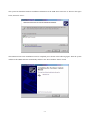
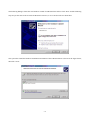
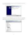
Model: UT-861
USB/RS-485/RS-422 4Port
Industrial Grade Opto-Isolated Interface Converter
Users’Manual
Instruction Manual
Content
1. Overview----------------------------------------------------------------------------------------------------------------------2
2. Main functions----------------------------------------------------------------------------------------------------------------2
3. Hardware installation and application-------------------------------------------------------------------------------------2
4. Performance-------------------------------------------------------------------------------------------------------------------3
5. Connector and signal---------------------------------------------------------------------------------------------------------3
6. Communication connection wiring diagram ------------------------------------------------------------------------------4
7. Troubleshooting---------------------------------------------------------------------------------------------------------------5
8. Product appearing diagram--------------------------------------------------------------------------------------------------5
9. Steps of driver installation-----------------------------------------------------------------------------------------------6-13
-1-
1. Overview
USB interface is gradually replacing the old-fashioned low-speed peripheral interfaces of PC with the continuous
development of PC industry. But many vital devices in current industrial environment is still designed using
RS-485/RS-422 interface, so the USB to RS-485/RS-422 converters are needed to transfer data between PC and
RS-485/RS-422 devices.
UT-861 is a universal USB/RS-485/422 converter which doesn’t need external power supply and has built-in
opto-isolator and DC/DC power isolation module. It is compatible with USB ,RS-422 and RS-485 standards, and
it can convert single-end USB signal to balanced differential RS-422 or 485 signal. The built-in photoelectric
isolator can provide isolating voltage up to 2500Vrms and it equips with high-speed transient voltage supressor
which is designed to protect the RS-422/RS-485 interface. The advanced TVS (TRANSIENT VOLTAGE
SUPPRESSOR) presents high-impedance state under normal conditions, and it can rapidly decrease the resistance
between its two ends while it’
s withstanding transient high-power impulse so as to absorb the high current and
clamp the voltage across it to a preset value, and then the following components will not be damaged by the
transient high-voltage impulse. This suppressor can effectively restrain lightning and ESD (electro-static discharge)
with lightning surge protection power of 600W for each line, and it also can restrain surge voltage and transient
over-voltage on the lines for any reason. Extremely small interelectrode capacitance ensures high speed data
transmission of RS-422/RS-485 interface.The RS-422/RS-485 end is connected through male DB9 connector.It
has built-in automatic transmit-receive switch without time delay. The unique I/O circuit can be used to
automatically control the direction of data flow without any hand-shaking signals(such as RTS and DTR) and
full-duplex(RS-422) and half-duplex (RS-485) can be implemented without jumper configuration,so as to make it
plug-and-play and applicable to all existing communication software and interface hardware.
UT-861 industrial photoelectric isolated interface converter can provide reliable connection for point-to-point or
point-to-multipoint communication. Maximum 128 RS-422 or RS-485 interface devices can be supported for the
point-to-multipoint communication. Data communication rate can be 300-128000BPS, and the power indicator
light and data traffic indicator light can be used for malfunction indication. USB to RS-422 and USB to RS-485
conversions are supported.
2. Main Features
Following communication modes are supported by UT-861 interface converter:
1) Point-to-point/4-wire full-duplex
2) Point-to-multipoint/4-wire full-duplex
3) Point-to-point/2-wire half-duplex
2) Point-to-multipoint/2-wire half-duplex
When the converter is connected for full-duplex or half-duplex communication, a matching resistor (120
Ohm,1/4W) should be connected to the wire terminal for avoiding signal reflection and interference.
3. Hardware Installation and Application
Please read this manual thoroughly and connect the USB cable to the USB port of computer before the installation
of UT-861 interface converter. USB/DB9 connectors are adopted for the input/output terminal and twisted cable or
screened cable can be used. RS-422 or RS-485 communication mode can be implemented without any
configuration and the connection and disassembly are very convenient. T/R+ and T/R- represent transmit and
receive A+/B-, RXD+/RXD- represent receive A+/B-,GND means common ground. T/R+ and T/R- should be
connected for point-to-point, point-to-multipoint half-duplex communication, and T/R+、T/R-、RXD+、RXDshould be connected for point-to-point, point-to-multipoint full-duplex communication.
-2-
4. Performance Parameters
1) Standards: Conforming to USB1.1, 1.0 and 2.0 standards and EIA RS-485 and RS-422 standard
2) USB signals: VCC、DATA+、DATA-、GND、FG
3) RS-485 signals:T/R+、T/R-、GND
4) RS-422 signals: T/R+、T/R-、RXD+、RXD-、GND
5) Operating mode: Asynchronous mode, point-to-point or point-to-multipoint mode, 2-wire half-duplex, 4-wire
full-duplex
6) Data flow control: Automatic data flow control technique is adopted to automatically determine and control the
data flow
7) Baud rate: 300-128000bps, automatically detecting the data rate
8) Load capacity: point-to-multipoint communication mode is supported, maximum 128 RS-422 or RS-485
devices are supported
9) Communication distance: 5000 meters for RS-485/422 interface (128000bps-9600bps) and no more than 5
meters for the USB port
10) Interface protection: 600W lightning and surge protection for each port, ±15KV ESD portection
11) Isolation degree: 2500Vrms isolation voltage for each port, 500DC contineous specialized DC/DC module
12) Isolation type: master/slave isolation, slave/slave isolation
13) Interface connection: B type female connector at USB side and DB9 male connector at RS-485/422 side
14) Signal indication: 9 signal indicator lights Power(PWR) transmit (TXD) receive (RXD)
15) Transmission media: twisted-pair or shielded cable
16) Baudrate: 128000bps to 300M
38400bps to U2.4KM
9600bps to U5KM
17) Dimension: 210mmX130mmX32mm
18) Environmental parameters: temperature of -25°C to 70°C, relative humidity of 5% to 95%
19) Supported OS: Win98/Win2000/WinXP/Win7/Linux
5. Connector and signals
1)DB9 PIN type: signal output and pin assignment of RS-485/RS-422
DB9 PIN type(PIN)
Signal output
1
2
3
4
5
6
7
8
9
T/R+
T/RRXD+
RXDGND
N/A
N/A
N/A
N/A
RS-422 full-duplex
connection
Transmit (A+)
Transmit(B-)
Receive(A+)
Receive(B-)
Ground
DB9 PIN type
1) USB-B type: USB signal input and pin assignment
-3-
RS-485 half-duplex
connection
RS-485 (A+)
RS-485 (B-)
Not connected
Not connected
Ground
6. Communication Wiring Diagram
USB to RS-422 conversion
1)
RS-422
communication
point-to-point/4-wire
full-duplex
2) RS-422 point-to-multipoint/4-wire
communication
full-duplex
RS-422 device
RS-422 device
3) full-duplex communication connection between
UT-861 interface converters
RS-422 device
RS-422 device
USB to RS-485 conversion
1) RS-485 point-to-point/2-wire half-duplex
2) RS-485 point-to-multipoint/2-wire half-duplex
RS-485 device
RS-485 device
3) Half-duplex communication connection between
UT-861 interface converters
RS-485 device
RS-485 device
-4-
7. Faults and trouble-shooting
1) Data communication fails
A. Check the USB cable connection
B. Check the RS-485/RS-422 connection
C. Check the power supply
D. Check the connection of terminals
E. Check if the receiving indication light flashes when receiving data
F. Check if the transmitting indication light flashes when transmitting data
2) Data lost or error
A. Check if the data rates and format of both communication devices are identical
8. Appearing diagram
-5-
9. Steps of driver installation
Following dialogue will pop up automatically when the UT-861 is connected to PC. Please select [install from list
or specified location (For advanced user)] and click “Next”.
The following dialogue of path selection will be shown, and please select [Don’t search. I’ll select the driver to be
installed by myself (D)] and click “Next”.
-6-
Then the hardware type dialogue will be shown and please scroll to (Universal serial bus controller) and click
“Next”.
The dialogue of “select the device driver you want to install for this hardware”will be shown and please click
[Have Disk...]
-7-
Then the dialogue of “install form hard disk”will be shown and please click (browse) to select the path of driver.
The dialogue of “find files”will pop up, and then select the CD path. Open it as shown in the following figure or
double click it.
-8-
Select the driver of installed converter type as shown in following figure. Click the folder of UT-861 and open it,
then select PCDriver folder.
Select the appopriate operating system (such as windows xp), and select (Winxp 2003.2000) and click to open it
or double click it.
-9-
In the popped up dialogue select FTDIBUS.INF and click it to open it, then a new dialogue with selected
FTDIBUS file will be shown.
Following is the driver path and then please click (OK).
-10-
The system has found the hardware installation information of the USB Serial Converter as shown in the figure
below, then click “Next”.
The USB Serial Converter installation wizard is completed just as shown in the following figure. Then the system
will detect the USB Serial Port automatically and show the “New hardware found" wizard.
-11-
The following dialogue shows the new hardware wizard of USB Serial Port. Please click “Next”and the following
steps are just the same as the wizard of USB Serial Converter, so we won’t describe it in detail here.
The system has found the hardware installation information of the USB Serial Port as shown in the figure below,
then click “Next”.
-12-
The USB Serial Port installation wizard is completed just as shown in the following figure. Now the driver of
UT-8814 has been installed completely.
After the driver has been installed correctly please have a look at the device manager to make sure whether there
is virtual COM port. If it’
s the first time to install the USB driver on this system then the default COM ports are
COM3.4.5.6 as shown in the following figure. Up to now the driver of UT-861 has been installed successfully.
-13-