1
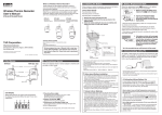
2. Connecting an Input Module
Specifications
Wireless Data Recorder
RTR-505
User’s Manual
Thank you for purchasing our product.
Carefully read this instruction manual before using this Unit.
Outline of RTR-505
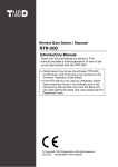
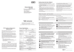
Part Names
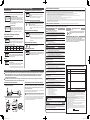
External Input Module Type
Splash proof (rated for use in daily life)
Antenna
RTR-505 is a Data Logger designed to measure and
record different items depending on the Input Module to
be connected: temperature (Thermocouple/Pt), voltage,
4-20mA, and pulse. The body is splash proof (rated for
use in daily life), which can be placed in an environment
between -40 and 80°C. Recorded data can be
automatically collected from the RTR-505 via wireless
communication with the Base Unit (sold separately), and
also viewed in graph and table form as well as printed
out by using the supplied software.
Device Name
Measurement Items (*1)
Recording Intervals
Logging Capacity
16,000 Readings
Recording Mode (*2)
Endless / One Time (Factory Default Setting: Endless)
LCD Displayed Items
Measurement, Recording Status, Recording Mode, Battery Life
Warning, Unit of Measurement, Full (Logging Capacity FULL),
Sensor Unconnected, Input Module Unconnected, Measurement
Range Exceeded, Display Range Exceeded)
Communication
Wireless Communication / Optical Communication
Interfaces
Wireless Communication
Specifications
RF Power
5mW
Radio Standard
Specifications
LCD Display
Optical
Communication
Area
Package Contents:
Data Logger (RTR-505), Tubed Lithium Battery (LS14250),
Input Module(*), Strap, User's Manual (this manual
including warranty)
* An Input Module included in the package differs
depending upon which "set model" has been purchased.
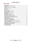
Module
Sensor Jack
RTR-505 is a Remote Unit. In order to use wireless
communication, it is necessary to purchase a Base Unit
separately. (Compatible Base Units: RTR-500NW, RTR500AW, RTR-500, RTR-500DC)
Wireless Data Recorder RTR-505 is referred to as the “Unit”
in this manual.
T&D Corporation
http://www.tandd.com/
817-1 Shimadachi Matsumoto, Nagano 390-0852 JAPAN
Fax:+81-263-40-3152
© Copyright T&D Corporation. All rights reserved.
This is printed using recycled paper.
RTR-505
Temperature / Voltage / 4-20mA / Pulse
Select from 15 choices: 1, 2, 5, 10, 15, 20, and 30 sec. / 1, 2, 5, 10,
15, 20, 30, and 60 min.
About 150 meters (500 ft) (if direct and unobstructed)
Power
Lithium Battery (LS14250) / Lithium Battery (CR2) (*3)
Battery Life (*4)
Waterproof Capacity
Dimensions
About 10 months (for temperature measurement)
Splash proof (rated for use in daily life) (*5)
H62×W47×D19mm (excluding protrusions and sensor)
Weight
About 56g (including battery / excluding Input Module)
Other
About 2 min. (when downloading 1 unit at full logging capacity)
About 160 sec. (when downloading 1 unit at full logging capacity at
2400bps)
(*1) Measurement items other than Pulse will have different measurement range depending on the Input
Module and sensor to be connected. For details, see the User’s Manual included with the Input
Module.
(*2) When using RTR-500NW or RTR-500AW as a Base Unit, only “Endless” can be selected.
(*3) The included lithium battery (LS14250) is not sold in stores. Please purchase the optional battery
set for low-temperature use (TR-11P2) for replacement.
(*4) Battery life varies depending upon the connected Input Module, measuring environment, frequency
of communication, Unit settings, and battery performance. For details, see "Estimated Battery Life"
in this manual.
(*5) This is the waterproof capacity of a Unit with an Input Module connected. Note that sensor connector of the Input Module is not water resistant.
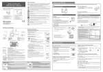
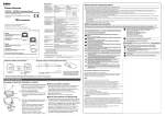
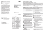
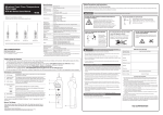
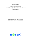
1. Installing the Battery
1. Remove the screws and open the cover.
Make sure to use the proper size and type of screwdriver. (Phillips head #1 screwdriver is recommended.)
2. Insert the included battery.
Do not remove the battery from its tube casing.
- If using a CR2 lithium battery, the tube is not necessary.
3. Check the rubber packing for any cuts or scratches and close the cover as it was when
opened.
- Dust or defects on the packing can adversely affect the waterproof capacity; in this case, remove the dust or replace the packing if it is damaged.
- Be sure to completely close the cover.
- Make sure not to over tighten the screws.
(Appropriate Tightening Torque: 20N cm to 30N cm{2Kgf cm to 3Kgf cm})
Cover
Rubber
Packing
Make sure that the module is completely
inserted until you hear a “click” sound.
LCD Displayed Items (see the following section #3)
Measurement, Unit of Measurement, Sensor Type, Operational Status
Measurement, Unit of Measurement, Sensor Type, Operational Status
RTR-505-V
Voltage
Voltage Module (VIM-3010)
Measurement, Unit of Measurement, Operational Status
RTR-505-mA
4-20mA
4-20mA Module (AIM-3010)
Measurement, Unit of Measurement, Operational Status
RTR-505-P
Pulse
Pulse Input Cable (PIC-3150)
Measurement, Unit of Measurement, Operational Status
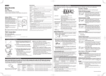
3. How to Read the LCD Display
When being used in very hot or cold environments the display may become difficult to read. This is not a malfunction.
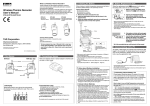
Basic LCD Display
After inserting the battery for the first time, nothing may appear or occur for about 10 seconds; this is not a malfunction.
If a new battery has been installed and nothing appears in the display, please remove and reinsert the battery.
When inserting a battery, make sure no water or foreign objects get inside the case.
Make sure that + and - are in the correct direction.
- Lithium batteries CR2 sold in stores may also be used, but if you are using in an environment below -20°C, above 60°C, or in a
situation such as transportation where continued vibration is likely to occur, we strongly suggest the purchase and use of the our
lithium battery LS14250. (Please purchase the optional battery set TR-11P2 which includes an LS14250.)
- When using an LS14250 type lithium battery, even though a new battery has been inserted the battery warning mark may remain
on for a short time. This is due to a special characteristic of the battery. Note that the longer the battery has been in storage the
longer the amount of time, from 10 minutes to about 1 hour, the battery warning mark will remain on. If during that time the Base
Unit is used to get the current status of the Remote Unit, the remaining battery level will show that the battery level is low.
- Please store the lithium battery LS14250 in a place that is 20°C or less.
- When changing a CR2 battery, we strongly suggest changing the rubber packing and the drying agent. Please purchase the
maintenance set TR-00P1 sold separately.
Estimated Battery Life
When a battery warning mark appears, try to replace the battery with a new
one as soon as possible.
In a normal temperature environment, where recorded data is downloaded
once a day or if monitoring is carried out once every ten minutes:
[REC] Mark
The recording status will appear.
ON: Recording in progress
BLINKING: Waiting for programmed start
[ONETIME] Mark
When the recording mode is set to "One Time",
this mark will appear. The factory default setting
is "Endless" and this mark will not appear.
Battery Warning
Mark
When it is time for the battery to be replaced, this
mark will appear.
Measurements and
Messages Area
Measurements or operational messages will appear here.
Sensor Type
The type of sensor connected to or set in the Unit
will appear.
Thermocouple Sensor: K, J, T, S
Platinum Thermal Resistance Sensor: Pt (Pt100),
PtK (Pt1000)
The unit of measurement for the display will apUnit of Measurement
pear.
Battery Replacement
1. When it is time for the battery to be replaced, a battery
warning mark will appear.
Please replace the battery as soon as possible if this
mark appears.
Notes about Battery Installation
-
About Lithium Batteries
Lithium Battery
(inserted into tube)
Set Model Number Measurement Item Input Module
Temperature
Thermocouple Module (TCM-3010)
(Type K, J, T, S)
Temperature
RTR-505-Pt
Pt Module (PTM-3010)
(Pt100, Pt1000)
RTR-505-TC
Operating Temperature Range: - 30 to 80°C
(The operating temperature range and measurement range is -40 to
80°C, but wireless communication cannot occur in an environment
of less than -30°C.)
A Base Unit is required (sold separately).
(Compatible Base Units: RTR-500NW, RTR-500AW, RTR-500,
RTR-500DC)
2011.09 16504760004 (1st Edition)
Screws
- The factory default settings are as follows: Recording Interval:10 minutes, and Recording Mode: Endless.
ETSI EN 300-220 (Frequency Range:869.7 to 870MHz)
Transmission Range
Communication
Speed
Optical Communication
Speed
Operating Environment
Insert an Input Module into the module jack. Once the Unit recognizes the module, the LCD display will change as
shown below and recording will start. (If you have purchased an RTR-505-P, the Unit has been set by default to start
recording upon installation of the battery.)
2. If you do not change the battery and continue using the
Unit, the measurement display will intermittently
display [bAtt].
- After this point the downloading of data can no
longer be done via wireless communication.
- Without changing the battery and attempting to use
optical communication to download recorded data,
the communication may be broken and if so all
recorded data may be lost.
- Recording will be continued.
Set Model Number
RTR-505-TC
Battery Life
About 10 months
RTR-505-Pt
About 10 months
RTR-505-V
RTR-505-mA
RTR-505-P
About 10 months
About 10 months
About 10 months
- The battery warning mark may appear sooner than noted above.
- Battery life will be shortened when: downloading data very often, setting the recording interval at less than ten seconds, or measuring in an environment below -20°C
(-4°F) or above 60°C (140°F).
Notes about Changing the Battery
- Before replacing a battery, please make sure to download any necessary data and
proceed with changing the battery.
- If + (plus) and – (minus) are mistaken, or if the battery terminals + and – are shorted,
the recorded data that is stored in the Unit will be lost.
- Downloading of data cannot occur while the battery is removed.
Example of Display
Display varies depending upon the model being used.
RTR-505-TC (Thermocouple)
Temperature measurement (Unit: °F / °C) will be
displayed. Sensor type will be displayed under the
measurement; the factory default setting is Type K.
By using the software included with the Base Unit,
you can change the sensor type.
RTR-505-Pt (Pt100 / Pt1000)
Temperature measurement (Unit: °F / °C) will be
displayed. Sensor type will be displayed under the
measurement; the factory default setting is Pt100.
By using the software included with the Base Unit,
you can change the sensor type.
RTR-505-V (Voltage)
Voltage measurement (Unit: V / mV) will be displayed. Due to the wide measurement range, the
Unit has been set by default to adjust the decimal
point automatically to display the measurement in V.
By using the software included with the Base Unit,
you can change the unit of display.
RTR-505-mA (4-20mA)
4-20mA measurement (Unit: mA) will be displayed.
3. If the battery is further left unchanged, the display will
automatically shut off.
If, at this time, a new battery is placed in the Unit,
[CHEC] will appear on the display after which recording will begin again using the previously set recording
conditions. Note however that all previously recorded
data will have been lost.
Continued on Back Page. >>
man_users-rtr505-1-eu.indd
1
2011/08/25
15:19:45
3. How to Read the LCD Display (continued from previous page)
RTR-505-P (Pulse)
Input Module Unrecognized (factory default)
There are two display methods for the pulse measurement. By using the
software included with the Base Unit, you can change the display method.
Pulse Rate (Max: 61439)
The most recent pulse count (Unit: P) for the recording interval period will be displayed. The display
will be refreshed every one-sixtieth of the recording
interval (at minimum of every one second). 10,000
pulse count will be displayed as "10.00KP", in units
of 10 pulse for display.
Total Pulse Count
The cumulative number of pulses (Unit: P) will be
displayed from 0 to 9999. The displayed count will
be refreshed every one second, and upon exceeding 9999, the count will start over again from 0.
Logging Capacity FULL
When Recording Mode has been set to “One Time” and
the Unit reaches its logging capacity of 16,000 readings,
recording will automatically stop and in the LCD the measurement and the word “FULL” will alternately appear.
Estimation of time until “FULL” is displayed
Period
30 seconds
1 minutes
10 minutes
About 4 hours About 5 days About 11 days About 111 days
-
-
-
-
-
-
-
-
-
-
-
Note that a RTR-505-P has been set to measure Pulse by
default, therefore the unit "P" will be displayed.
Input Module Unconnected or Damaged
This will appear if the Unit cannot confirm a connection with the Input Module after having recognized it.
(with unit of display)
If nothing is displayed after reconnecting the sensor to the
Unit, there is a possibility that the sensor or the Unit has been
damaged.
60 minutes
About 1 year and
10 months
Data Transmission via Wireless Communication
The measurement and the word "SEnd" will alternately
appear when data is being sent via wireless communication to the Base Unit. Recording will continue during
wireless transmission.
Safety Precautions and Instructions
Sensor Unconnected or Damaged
It may cause fire or malfunction.
If water or a foreign object enters the case, immediately remove the battery
and cease using it.
It may result in malfunction or unexpected accidents.
If nothing appears on display after reconnecting the sensor to
the Unit, there is a possibility that the sensor or the Unit has
been damaged.
Store the Unit and accessories out of the reach of children.
Not doing so may cause an unexpected accident.
If any smoke or strange smells are emitted from the Unit, immediately remove
the battery and stop using.
Measurement Range Exceeded
Continued use may cause fire or electrocution.
This Unit has been designed for private and/or industrial use only. It is not for
use in situations where strict precautions are necessary such as in connection
with medical equipment, where directly or indirectly.
Harmful gases or chemicals may cause corrosion and/or other danger to the
Unit. Also, by coming in contact with hazardous substances, harm may occur
to the people handling the Unit. Therefore, do not use or store the Unit in any
environment that is exposed to chemicals and harmful gases.
Battery life varies depending upon measuring environment, frequency of
communication, Unit settings, and battery performance.
When using the Unit in a low-temperature environment (below -20°C), the
battery power will be depleted more quickly than when using under normal
temperature conditions.
When measuring voltage, the measurement in the
LCD display will blink if a measurement exceeds a set
display range. (Only when the Unit has been set to a
"fixed decimal point" for display)
Battery terminals may provide insufficient contact due to age or vibration.
This may lead to data loss.
The Unit becomes splash proof (rated for use in daily life) only after the Input
Module has been connected.
Without the module connected, neither the module jack nor the connector part of the temperature
sensor on the Unit is water resistant; make sure not to get wet.
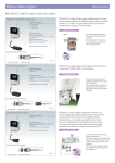
Communication with a PC enables the following:
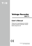
1. Follow directions as issued in the software to connect
By using a software included with the Base Unit, it is possible to carry out Remote Unit registration, change recording
settings in the Unit, download recorded data to a PC, and
view downloaded data.
If the Unit is not to be used for a long period of time, store it in a place where it
is not exposed to high temperature and high humidity.
Guarantee Period
Do not remove or reinsert the battery once it has been set; continue using until
battery power is depleted. Always use a new battery for replacement.
Date of Purchase
To maintain waterproof capacity, we suggest periodically changing the parts
inside the case.
If the rubber packing should be damaged or deteriorated, please replace it along with the drying
agent.
If the Unit is subjected to significant temperature change while wet, it may
cause condensation inside the case.
Especially be careful with temperature changes from high to low; if the Unit has condensation on
the inside, it may cause malfunction, damage, and/or unexpected accidents.
It may cause damage or malfunction.
Do not put fingers or foreign objects into the modular jack.
Do not use or store the Unit in places such as listed below. It may result in
malfunction or unexpected accidents.
- Areas exposed to direct sunlight
- Areas exposed in water or high-pressure water flow
- Areas exposed to organic solvents and corrosive gas
- Areas exposed to strong magnetic fields
- Areas exposed to static electricity
- Areas near fire or exposed to excessive heat
- Areas exposed to excessive dust, dirt and smoke

Contact with oil may cause cracks to appear in the casing of the Unit.
When using this Unit in environments where such oils are present, please
insure that it is protected from contact through use of a polyethylene bag
or other means.
Notices about using the Input Modules
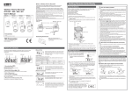
Optical
Communication Area

Slitted Area
man_users-rtr505-1-eu.indd
2
1 year from date of purchase
Customer's name
Address
Phone No.
Distributor's name
Do not drop or expose the Unit to a strong impact.
The factory default settings are as follows: Recording Interval: 10 minutes, Recording
Start: Immediate Start, and Recording Mode: Endless.
-- Proper communication may not be possible in the following situations: where temperatures are very high or very low, in an environment with intense brightness (higher
than 5,000lx), or when the remaining battery life for the Data Logger is very low.
-- The time necessary to download one RTR-505 Unit at full logging capacity varies
depending upon the Base Unit being used.
Wireless Data Recorder RTR-505 Warranty
If the Unit has condensation on the inside, it may cause malfunction and damage.
Not doing so may result in improper operation.
Notices about Optical Communication with a Base Unit
Ex: RTR-500
Wireless products cannot be used in countries other than where those products have
been approved for use, according to that country's wireless regulations.
T&D Corporation shall in no manner whatsoever take responsibility for the usage of
these products, nor be liable in any manner for legal consequences stemming from
the usage of these wireless products in unapproved areas.
CAUTION
Display Range Exceeded
Communicating with the Computer
RTR-505

Important Notice
Please be careful not to touch the Unit during or after use in overly hot or cold
environments; it may cause burns or frostbite.
The message "OL" will appear if a measurement exceeds the measurement range.
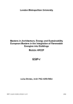
In order to download data from the Unit via wireless communication or change recording settings in the Unit, it is necessary to
register a RTR-505 Unit as a Remote Unit to a Base Unit (sold separately). Remote Unit registration can be carried out by
connecting the Base Unit to a PC via USB cable and using the software included with the Base Unit to carry out optical
communication with the Remote Unit.
For details about available operations via wireless communication or how to make recording settings, see the Introductory
Guide included with the Base Unit or see the application’s Help.
optical communication areas and slitted areas.
This device complies with technical specifications required under
EN 301 489 (with battery and AC Adaptor), EN 300-220, and EN
60950-1.
Do not use any other batteries than those that are specified in this manual.
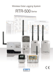
4. Registering as a Remote Unit (Communication with a PC)
2. Place the Data Logger on the Base Unit to align the
CE Statement
It may result in malfunction or unexpected accidents.
-- The first time a battery was inserted after purchase
-- When the battery is replaced after having been taken out for a long period
-- When the battery is replaced after the battery power has been lost
Communication Cable
Compliance Information
DANGER
If this appears, all data that was stored in the Unit will
have been erased.
This message will appear under the following conditions:

* Please carefully observe the following safety measures when using our product.
Do not take apart, repair or modify the Unit.
Check
the Base Unit to your PC.
All rights of this manual belong to T&D Corporation. It is prohibited to use, duplicate and/or arrange a part or whole of this Manual without the permission of T&D Corporation.
All registered trademarks, company names, product names and logos mentioned herein are the property of T&D Corporation or of their respective owners.
Specifications, design and other contents outlined in this manual are subject to change without notice.
Please follow the safety precautions outlined in this manual carefully. We cannot guarantee nor are we responsible for safety if this product is used in any manner other than was intended.
On-screen messages in this manual may vary slightly from the actual messages.
Please notify the shop where you purchased this product or T&D Corporation of any mistakes, errors or unclear explanations in this manual.
T&D Corporation accepts no responsibility for any damage or loss of income caused by the use of our product.
This product has been designed for private or industrial use only. It is not for use in situations where strict safety precautions are necessary such as in connection with medical equipment, whether directly or indirectly.
We are not responsible for any malfunction or trouble caused by the use of our product or by any problem caused by the use of measurement results of our unit. Please be fully aware of this before using our product.
This manual cannot be reissued, so please keep it in a safe place.
Please read the warranty and provisions for free repair carefully.
To prevent any loss or damage to our customers, other people and/or property, and to ensure the proper use of our products we ask that before using our product you carefully
read, understand and follow the safety rules and precautions for our products as outlined below.
This will be displayed when a sensor has not been
connected to the module or the wire has been broken.
Recording is in progress and so is battery consumption.
Other Marks or Messages on Display
Recording
1 second
Interval
This will appear if, after purchasing, the Input Module
has never been connected to the Unit. (No unit for
display)
Important Notices and Disclaimers
In order to properly use this product, please carefully read this manual before using.
T&D Corporation accepts no responsibility for any malfunction of and/or trouble with this product or with your computer that is caused by the improper handling of this product
and will deem such trouble or malfunction as falling outside the conditions for free repair outlined in the attached warranty.
When making "Adjustment Settings" in the Adjustment Tools application, the
adjustment values will be saved to the Input Module. Therefore, when an Input
Module is replaced, it is necessary to re-make any desired adjustment settings to be
written into the newly connected module.
Address
Phone No.
Object of Repair
Method of Repair
Main Unit (excluding sensors and any other options.)
Send in for Repair
Provisions for Free Repair
1. If the Unit does not work properly despite the fact that the customer used it properly and in line with
the manual, the Unit shall be repaired free of charge through the distributor which sold the Unit.
2. If the customer requests free repair because of trouble within the warranty period, bring or send the
Unit along with the warranty to the distributor.
3. If you have moved after purchasing, or there are difficulties contacting the distributor from which you
purchased the Unit, please contact T&D directly for service.
4. Free repair is not available in the following cases even though it is within the warranty period:
1.Trouble or damage was caused by careless operation, natural disaster, fire, public pollution, or use
of a power source other than specified.
2.If repair, adjustment, disassembly or modification of the Unit has been carried out by a person other
than a T&D authorized engineer.
3.Trouble or damage was caused by transportation, movement or dropping of the Unit after purchase.
4.Failure to submit the Warranty or failure to fill in all items required in the Warranty.
5. The Warranty cannot be reissued.
This Warranty only promises customers free repair within the period and conditions clarified in this
Warranty. Therefore, the customer's legal rights will not be limited by this Warranty. For further information on repair and other service questions after the termination of the warranty period, contact your
distributor.
2011/08/25
15:19:46