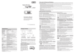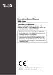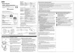
1
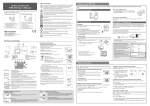
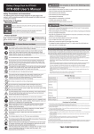
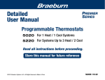
Notes about Operation
This product has been designed for use in normal living conditions, and is not suited
for controlled environments such as a CO2 incubator. When measuring outdoors,
avoid exposure to sunlight, dust, rain, or wind. Also make sure to use in the
operating environment indicated in the specifications.
Wireless CO2 Recorder
RTR-576 User's Manual
Do not connect an RTR-576 to your computer before first installing the supplied software that comes with the Base Unit you are using.
Turn on the
Connect the Sensor
This product cannot measure CO or O2. Do not use it for purposes such as avoiding
O2 deficiency, CO intoxication or any other health related purpose.
Thank you for purchasing our product. To ensure safe and proper operation, please
read this manual thoroughly before use.
RTR-576 Package Contents
Setting up the RTR-576
• See Button Operations
switch.
For one to two weeks after installation of the unit, CO2 concentration measurements
may fluctuate suddenly. This is due to the normal operation of Auto Calibration and
is not a malfunction of the RTR-576.
RTR-576-H Package Contents
Do not use or store the unit in areas exposed to direct sunlight and abrupt changes
in temperature.
Wireless CO2 Recorder (RTR-576)
Temperature/Humidity Sensor (THA-3001)
AC Adaptor (AD-0638)
USB Communication Cable (US-15C)
AA Alkaline Battery x 4
User's Manual (Warranty Included)
Turn ON the Power
AC Adaptor
When measuring and recording over long periods of time, please
use a supplied AC adaptor.
The measurement accuracy of the CO2 sensor can not be guaranteed for CO2
concentrations of 5,000ppm or more.
Four AA Alkaline Batteries
http://www.tandd.com/
© Copyright T&D Corporation. All rights reserved.
2012.09. 16504800003 (1st Edition)
Printed on recycled paper.
Please set up the Base Unit first before the RTR-576.
1.
Checking the Power Supply Condition
Whether the battery mark is "blinking" or "on" indicates the source of power. This mark will not
appear when batteries are not installed.
Lift off the cover.
2.
•
•
•
•
Checking the Battery Level
The battery level will be shown in three stages as below.
AC Adaptor Jack
USB Communication Cable Jack
Serial Communication Cable Jack
(RS-232C)
External Alarm Terminal (EXT ALM)
Switch
At the beginning of every 2,000 readings the scale will be marked from left to right.
Logging capacity is 8,000 readings.
[COM] Mark
Shows communication status but not displayed normally.
ON: The unit is connected to a PC with a USB cable.
RAPID BLINKING: The unit is in communication via USB or wireless communication.
Rec. Mode
Endless:
Recording mode settings can be made by using the supplied software.
Upon reaching the logging capacity of 8,000 readings, the oldest data will be
overwritten and recording will continue.
One Time: Upon reaching the logging capacity of 8,000 readings, recording will automatically stop
and in the LCD the current measurement and the word “FULL” will alternately appear.
Battery Mark
Shows source of power and voltage level. (See "Interpreting the Battery Mark" for
details.)
Current Tempera- Shows the current readings for temperature (°C / °F) and humidity (%RH). Pressing the
ture and Humidity
button will change the measurement item to be displayed. This area is also
Readings Area
used to display messages.
Current CO2
Readings Area
• If you have connected a unit without having installed the software supplied with the Base Unit, and
the New Hardware Wizard has opened, please close the wizard window and disconnect the USB
cable from your computer.
• For details see the Introductory Manual that came with your Base Unit.
[Regisitration Window]
Atmospheric Pressure Correction:
Measurement results of CO2 concentration are
affected by atmospheric pressure. When high
measurement accuracy is required, we recommend
that Atmospheric Pressure Correction be carried
out before a recording session is started.
Registration Window for RTR-576 :
In the Registration Window for RTR-576, click the pull
down menu of [Atmospheric Pressure Correction] to
open the settings box. Directly enter the pressure (hpa)
in the [Atmospheric Pressure] field.
Calculate Atmospheric Pressure from Altitude:
This setting can also be made by having the software
calculate the estimated pressure at the altitude (meters)
entered by the user.
Button Operations
to
and another
If "Button Lock" has been set to ON in the software supplied with the Base Unit, the
operational buttons will not be active.
Sleep Mode (stopping measurement and recording)
After Stage , if the batteries are not changed but remain in use, the unit will
enter sleep mode and stop measurement and recording in order to protect
recorded data until this point.
Data Scale
Make sure to use new batteries of the same kind.
Make sure not to mistake + / -.
Do not insert or change batteries with wet hands.
Be sure to completely close the cover.
Wizard Window
Battery Power - Getting Low
It is recommended to change the batteries as soon as possible.
• When running on batteries only, it will take about 24 hours to go from Stage
24 hours from Stage
to .
Shows recording status
ON: Recording in progress
BLINKING: Waiting for programmed start
OFF: Recording stopped
Insert the supplied batteries.
Battery Power - OK
Battery Power - Too Low
If the battery power has become low while running on batteries
only, it is impossible to measure and record CO2 concentration.
Also, errors may occur during wireless communication.
[REC] Mark
Remove the battery cover from the back of the
unit.
Mark blinks when running on
battery power.
ON (Running on external power):
The battery mark will be on when using the AC adaptor.
Operation Buttons
Button,
Button,
Button
Battery Cover
Temperature and Humidity Sensor Jack
If upon USB connection, the [New Hardware Detection Wizard] opens, it is necessary to follow
directions to install the USB Device Driver.
USB Connection
While pressing down on the triangular mark, slide
the cover to the bottom of the unit.
Interpreting the Battery Mark
Antenna
CO2 Sensor Area
(Internal)
LCD Display
When the wizard window appears:
Install the Battery
If battery power is lost, all recorded data stored in the unit will be erased. Do not
leave the unit without batteries.
BLINKING (Running on battery):
The battery mark will blink on the LCD display when operating on battery
power only.
Register the RTR-576 as a Remote Unit by using the software supplied with the
Base Unit. After connecting an RTR-576 to your computer via USB cable, carry out
registration using your software: Settings Utility (*) - [Remote Unit Settings] Menu
- [Register] Button
* includes [RTR-500W Settings Utility], [RTR-500 Settings Utility], and [RTR-500DC Settings Utility].
If running on only batteries, the estimated battery life is about two
days. Keeping batteries in the unit allows a backup source of
power for when and if electrical power is cut from the AC adaptor.
• Leaving alkaline batteries in the unit for a long period of time may
cause battery leakage and corrosion. When using as a backup source,
we recommend that you change the batteries every few years.
Part Names and LCD Display
for notes about turning off the
Register as a Remote Unit
Do not expose the unit to a strong impact. This will adversely affect measurement
accuracy and may cause the case to break resulting in bodily injury.
As a Remote unit, RTR-576 requires a Base Unit to carry out wireless
communication.
(Compatible Base Units: RTR-500, RTR-500NW/500AW, RTR-500DC)
"ON" position
After switching on the unit, it will take about one minute to display the normal CO2
concentration.
To help prevent deterioration of the unit, do not use or store the unit in areas
exposed to cigarette smoke, corrosive, explosive or organic gases or dust in the air.
• Wireless CO2 Recorder (RTR-576)
• High Precision Temperature/Humidity
Sensor (HHA-3151)
• AC Adaptor (AD-0638)
• USB Communication Cable (US-15C)
• AA Alkaline Battery x 4
• User's Manual (Warranty Included)
switch.
Warm-up Time for CO2 Sensor
Do not allow the unit to become wet. Do not use or store the unit in places where
condensation occurs.
•
•
•
•
•
•
switch.
After setting up the power supply, turn on the
Button: Starting and Stopping Recording
• Upon replacing the batteries with new ones, the display will return to the
current readings display.
• Download the recorded data into the PC before re-starting recording.
Starting Recording
• It is possible to start recording even while waiting for a programmed
recording to start.
• Upon the start of recording, all previously recorded data in the RTR-576
will be deleted.
Removing the Batteries during Recording
If the batteries are removed when running on battery power only,
the Unit will start a sixty-second countdown.
2.
To continue recording, before the countdown comes to an end,
insert new batteries or connect the AC adaptor to supply power.
3.
If power is not supplied within 60 seconds, the Unit will enter
sleep mode.
It is possible to check the recording interval during recording or while waiting for a programmed recording to start.
1.
By pressing the
button for
about two seconds, the currently set
recording interval will appear on the
LCD display.
2.
If no operation is carried out after the
recording interval has been displayed,
the current measurement readings will
return to the LCD display.
Press the
button for about two seconds until the [REC] mark
appears on the display.
Erasing recorded data
If the battery is further left unchanged, the display will automatically shut off and
all previously recorded data will be lost.
Recording settings will remain.
1.
Button: Checking Recording Interval
10 minutes
10 seconds
Stopping Recording
Press the
button for about two seconds until the [REC] mark
disappears from the display.
Countdown
Button: Changing the LCD Display Pattern
It is possible to change the current readings display for temperature and humidity (upper row).
CO2 concentration (lower row) is always displayed.
1.
Shows the current readings for CO2 concentration (ppm). This area is also used to
display messages.
With each pressing of the
Button: Changing the Recording Interval Setting
Recording interval settings cannot be changed while a recording session is in progress.
1.
2.
Stop recording.
3.
With each pressing of the
button the recording interval time will change; stop
pressing the button when the desired interval appears.
4.
Restart the recording session.
button the item on the display will change.
Temperature and Humidity: The display will alternate every one second.
Press the
button for about two seconds to display the currently set recording
interval on the LCD screen.
Temperature only
Messages and Display on the LCD
Settings Messages
Button Lock
When "Button Lock" has been set to ON in the software supplied with the Base Unit,
operational buttons are not active.
Memory Full
When recording mode has been set to “One Time” and the unit reaches its logging capacity
of 8,000 readings, the measurement and the message [FULL] will alternately appear in the
LCD. Stop recording and download the recorded data before re-starting recording. Memory
"FULL" does not occur when in "Endless" mode.
When [
] appears in the following:
Temperature and Humidity Display Area
This appears when the temperature/humidity sensor is not connected to the RTR-576,
the connection is loose, the wire is broken, or when power has just been turned ON.
If after re-connecting the sensor, measurements can still not be displayed, it is very
possible that the sensor or the logger is defective or has been damaged.
Turning Off the
Humidity only
2.
When the desired display pattern appears, stop pressing the button.
CO2 Concentration Display Area
This appears when power has just been turned ON. If measurements don't appear in
the display after waiting for a considerable time, there is a possibility that the sensor is
defective or has been damaged. Also, the CO2 sensor will not work if battery power is
low.
Distributed by MicroDAQ.com, Ltd.
Switch
During recording or when the "Button Lock" is set to ON in the software, the power
cannot be turned off even by using the
switch.
1.
Stop recording.
2.
Turn off the
switch.
• If the RTR-576 is connected to an AC adaptor, standby power will be supplied even after turning off
the
switch, allowing the CO2 sensor to continue operation. Therefore, the CO2 sensor lamp
will continue to flash periodically.
• When running on battery power only, CO2 sensor stops working if the
switch is turned off.
www.MicroDAQ.com
(603) 746-5524
Getting Ready to Use External Alarm Terminal
Specifications
It is possible to connect an external device such as siren or lamp to the RTR-576.
Please make sure to check specification details of the external alarm terminal before
purchasing or getting an external device ready for connection.
About the External Alarm Terminal (EXT ALM)
Enabling
Warnings
Warning Output
(OUT)
Warning Output
(Enable / Disable)
Internal Pull-up: 3V 100 kΩ
Maximum Input Voltage: 30V
Output Terminal
(Warning Output)
Open Drain Output
Voltage when OFF: DC less than 30V
Current when ON: less than 0.1A
Resistance when ON: 15Ω
Measurement
Channels
Disabled
Electrostatic Capacitance
Temperature 1ch
Humidity 1ch
Temperature 1ch
Humidity 1ch
°C, °F
%RH
°C, °F
%RH
Explanation of Picture Symbols
0 to 99 %RH
Denotes an important warning
or caution.
0 to 55 °C
Accuracy
±0.5 °C
10 to 95 %RH
-30 to 80 °C
±0.3°C
[at 0 to 50 °C]
±0.5°C
[at all other
temperatures]
±5 %RH
[at 25 °C, 50 %RH]
0.1 °C
1 %RH
Response Time (90%): Approx. 7 min.
About the Compatible Connector
±2.5 %RH [ at 25 °C, 10 to 85 %RH]
±4.0 %RH [ at 25 °C, 0 to 10 % or
85 to 99 %RH ]
At temperatures other than 25 °C
and ≥ 0 °C, add ±0.1 %RH per
degree of difference from 25.
Humidity Hysteresis: ±1.5 %RH or
lower (*2)
0.1 °C
Response Time (90%):
Approx. 7 min.
0.1 %RH
Response Time (90%):
Approx. 20 sec.
CO2 Sensor
The JST Connector PAP-04V-S is compatible with the external alarm terminal. For questions
concerning sales of the connector, please directly contact JST Mfg. Co., Ltd.
http://www.jst-mfg.com/
Auto Calibration Function for CO2 Sensor
What is "Auto Calibration" ?
Auto calibration is a function designed to enable long-term accurate measurements for the
RTR-576 by gradually adjusting the lowest measured weekly CO2 concentration to the global
average concentration ( atmospheric CO2 level of 400 ppm ).
CAUTION
These entries are actions that if taken may lead to physical injury or damage to persons or
things.
Platinum Resistance
Units of Measurement
Responsiveness
These entries are actions that, if taken, may cause serious personal physical damage or
death.
Polymer Resistance
Measurement
Resolution
Enabled
DANGER
Thermistor
GND
The connection between
and
decides whether Warning Output
is enabled or disabled. If a warning condition occurs while Warning
Output is enabled, a connection between
and
will be
established and a warning will be output.
HHA-3151(High-Precision Type)
THA-3001
Temperature/Humidity
Sensor (External)
CO2 Sensor (Internal)
NDIR
Measurement
Channels
CO2 Concentration 1ch
Units of Measurement
ppm
Measurement Range
0 to 9,999 ppm
Accuracy
± ( 50 ppm + 5 % of reading) [ at 5,000 ppm or less ] (*3)
• All rights of the attached documents belong to T&D Corporation. It is prohibited to use, duplicate and/or arrange
a part or whole of the attached documents without the permission of T&D Corporation.
Explanation of Warning Symbols
RTR-576-H
Temperature / Humidity Sensor
Measurement Range
(*1)
GND
Explanation of Symbols
RTR-576
DANGER
Denotes a forbidden action.
Denotes an action that
should be carried out.
To Prevent Serious Accidents
Do not disassemble, repair or modify the unit and accessories.
We shall not guarantee the unit's operation if it has been connected to a PC using a USB hub or a USB
extension cable.
Logging Capacity
8,000 data sets ( One data set consists of readings for all channels in that type of unit )
To prevent damage to the unit from static electricity, remove static electricity from your body by touching
metal around you (such as a door knob and window frame) before touching the unit.
Recording Interval
Select from 15 choices: 1, 2, 5, 10, 15, 20, 30 sec. or 1, 2, 5, 10, 15, 20, 30, 60 min.
Recording Mode (*4)
Endless ( Overwrite oldest data when capacity is full ) or One Time ( Stop recording when capacity is full )
Communication
Interfaces
Wireless Communication ( Short Range Radio Communication )
FCC Part15 Section247 / IC RSS-210 (Frequency Range: 902 to 928 MHz, RF Power: 7 mW)
USB Communication
Serial Communication ( RS-232C ) (*5)
Wireless Transmission
Range
Approx. 150 meters (500 ft) if direct and unobstructed
External Alarm
Terminal
Output Terminal: Open Drain Output
( Voltage when OFF: DC less than 30V / Current when ON: less than 0.1A / Resistance when ON: about
15Ω )
Power
AC Adaptor ( AD-0638 ), AA Alkaline Battery ( LR6 ) x 4
Battery Life (*6)
Approx. 2 days ( batteries only without AC adaptor )
Dimensions
H 96 mm x W 66 mm x D 46 mm ( excluding protrusions and sensor )
Antenna Length: 60 mm
• Areas exposed to static electricity
Weight
Approx. 220 g ( including battery, excluding sensor )
• Areas exposed to dampness
• Do not expose the sensor to a strong impact. This may adversely affect measurement accuracy
and cause damage or malfunction.
Operating
Environment
Temperature: 0 to 45 °C
Humidity: 90 %RH or less ( no condensation )
• Areas subject to condensation or wet areas
• When the sensor is not to be used for a long period of time, please store it at normal
temperature and humidity.
Compatible Base
Units
RTR-500, RTR-500NW/500AW, RTR-500DC
• Areas exposed to excessive smoke, dust or dirt.
Cautions about using the Temperature/Humidity Sensors
• If extremely severe temperature changes occur, the humidity measurements may appear
abnormal. Once the sensor's temperature becomes stable, the measurements will return to
normal.
• Do not connect the sensor to any data logger other than those specified by T&D Corporation.
• Do not use the sensor on the human body.
• Continued use may cause a decrease in the sensor’s accuracy and sensitivity even under
normal operational conditions.
• Do not expose to condensation, dampness, corrosive gases, or organic solvents (or insecticides
for High Precision Temperature/Humidity Sensors).
• This sensor is not water resistant. Do not allow the sensor to become wet. If the sensor gets
wet, immediately remove the sensor from the unit and wipe it with a clean cloth as soon as
possible. Then allow the sensor to dry in normal room temperature before using it again.
Options
Temperature/Humidity Sensor:
THA-3151
Place and store the unit and accessories out of the reach of children.
Further, T&D is not responsible for any damage, malfunction or trouble, whether direct or indirect, caused by
the use of our products.
Do not use any power or sensors other than those specified by T&D Corporation.
If the unit produces heat, emits smoke or a strange smell, or makes unusual noise, immediately unplug the
AC adaptor, remove the batteries, and stop using it.
CAUTION
*1: Make sure to use the data logger within the operating environment as listed in the specifications.
*2: When used in environments where temperature and humidity are over the values of 50°C 75%, 60°C 50%, 70°C 35%, and 80°C 25%,
sensor hysteresis may fluctuate by values greater than ±1.5%RH. Under certain circumstances, it may take some time to return to nor.
*3: Stated value is the measurement accuracy of the CO2 sensor when Auto Calibration is operating properly. A change in atmospheric
pressure directly influences the reading of CO2, which can cause measurement errors; a decrease in pressure by 10 hPa result.
*4: Only “Endless” is available when using RTR-500W for Windows.
*5: For communication with the Data Collector RTR-500DC (Note: Optional serial communication cable TR-6C10 is required.)
*6: Battery life varies depending upon the ambient temperature in which it is used, the recording interval, the frequency of communication, and
the battery performance. All estimates are based on operations carried out with a new battery and are in no way.
The specifications listed above are subject to change without notice.
• Areas subject to high temperatures such as near fire or heating equipment
Sensor Extension Cable: TR-1C30
Compliance Information
FCC Statement
This device complies with Part 15 of the Federal Communications Commission (FCC) rules. Operation
is subject to the following two conditions: (1) This device may not cause harmful interference, and (2)
This device must accept any interference received, including interference that may cause undesired
operation.
Caution:
Changes or modifications not expressly approved by the party responsible for compliance could void
the user's authority to operate the equipment.
• Areas exposed to excessive vibration
CAUTION
Other Precautions
• Use the unit in the specified operating environment. Do not use it for any purpose other than for which it was
designed.
Recording Mode: Endless
Recording Interval: 10 min.
LCD Display Pattern
Alternating Display
This device complies with RSS-210 of the Industry Canada (IC). Operation is subject to the following two
conditions: (1) This device may not cause harmful interference; and (2) This device must accept any interference
received, including interference that may cause undesired operation.
Ce dispositif est conforme à la norme RSS 210 d’Industrie Canada.
L’utilisation de ce dispositif est autorisée seulement aux conditions suivantes : (1) il ne doit pas produire de
brouillage et (2) l’utilisateur du dispositif doit être prêt à accepter tout brouillage radioélectrique reçu, même si ce
brouillage est susceptible de compromettre le fonctionnement du dispositif.
This radio transmitter (IC 5558A-50040) has been approved by Industry Canada to operate with the antenna
types listed below with the maximum permissible gain and required antenna impedance for each antenna type
indicated. Antenna types not included in this list, having a gain greater than the maximum gain indicated for that
type, are strictly prohibited for use with this device.
Le présent émetteur radio (IC 5558A-50040) a été approuvé par Industrie Canada pour fonctionner avec les types
d'antenne énumérés ci-dessous et ayant un gain admissible maximal et l'impédance requise pour chaque type
d'antenne. Les types d'antenne non inclus dans cette liste, ou dont le gain est supérieur au gain maximal indiqué,
sont strictement interdits pour l'exploitation de l'émetteur.
Name
RTR-576 Antenna (Included)
Type
Dipole
Gain
0 dBi
Impedance
50 ohm
Important Notices
Wireless products cannot be used in countries other than where those products have been approved for use, according to
that country's wireless regulations.
T&D Corporation shall in no manner whatsoever take responsibility for the usage of these products, nor be liable in any
manner for legal consequences stemming from the usage of these wireless products in unapproved areas.
817-1 Shimadachi Matsumoto, Nagano 390-0852 JAPAN
Fax: +81-263-40-3152 E-mail: [email protected]
http://www.tandd.com/
We have opened an English Website for your convenience. Here you can find information about our
company, news, products, upcoming events, software and Introductory Manual downloads, as well as,
ther support. Please stop by and see what we have to offer.
Wireless CO2 Recorder RTR-576 Warranty
• Do not use the unit in wet areas or places exposed to water such as bathroom.
• Do not insert any foreign objects into any of the units' jacks.
• Please note that this User's Manual has been written based on the presupposition that details about set-up of
any necessary equipment to enable network connection have already been taken care of by the user and that
connection has been confirmed as workable. T&D Corporation shall not be responsible for any damages which
a contractor, a user or a third party may suffer, whether direct or indirect, due to the inability to communicate or
use communication devices.
Notes and Precautions for Installing Wireless Communication
Devices
When installing wireless communication devices take special care in selecting locations so as to ensure proper
communication. Note that even after a successful installation, due to changes in environmental conditions,
communication errors may occur when restarting the system.
Measurement Range:
Temperature -30 to 80°C, Humidity 0 to 99 %RH
Long Term Stability:
± 1%RH/yr, ± 0.1°C/yr
Cable Length: 1.5 m
This device has been designed to operate with the supplied antenna only. Use of any other antenna is strictly prohibited.
• Condensation may occur inside the case when a unit is moved from one environment to another where there is
a great difference in temperature. Be careful to avoid condensation.
• If the unit gets dirty, wipe it with a clean cloth.
Recording Conditions
Note about Antenna Usage
For product information or questions contact us at:
• As far as possible, try to keep wireless communication devices away from metals and set them up in high
unobstructed positions.
• Please take note that in many instances, walls, floors, stairs, fences and desks will contain metals. In order to
carry out communication between indoor and outdoor units, please locate indoor units near a window so that
radio waves can be easily transmitted.
Guarantee Period
1 year from date of purchase
Date of Purchase
Customer's name
Address
Phone No.
Distributor's name
Address
• Please install the Unit more than 30 cm away from walls or boards containing metal.
Wall Attachment: AT-76K
• If the Unit is placed in a metal container such as a freezer or refrigerator, the possible wireless communication
range will be shortened. In most cases radio waves are transmitted via doors and door openings so place the
Unit as near to doors as possible.
Phone No.
• As far as possible, keep the Unit away from noise-emitting sources.
Possible to use up to three extension cables per
temperature / humidity sensor
Compatible Sensor:
THA-3001, THA-3151, HHA-3151
Temperature Durability: -25 to 60°C
Material: Vinyl Coated Electrical Wire
Cable Length: 3 m
• Please read the warranty and provisions for free repair carefully.
• Areas exposed to strong magnetic fields
CAUTION
Measurement Range:
Temperature 0 to 55°C, Humidity 10 to 95 %RH
Measurement Resolution:
Temperature 0.1°C, Humidity 1 %RH
Accuracy:
Temperature ± 0.5°C,
Humidity ± 5 %RH (at 25°C and 50%RH)
Response Time ( 90% ) : Approx. 7 min.
Cable Length: 1.5 m
• Please notify the shop where you purchased this product or T&D Corporation of any mistakes, errors or unclear
explanations in the attached documents.
T&D Corporation accepts no responsibility for any damage or loss of income caused by the use of our product.
Do not place or store in the following areas:
• Areas exposed to direct sunlight
Initial Settings
High Precision Temperature/Humidity
Sensor: HHA-3151
• On-screen messages in the attached documents may vary slightly from the actual messages.
IC Statement
Do not drop or expose the unit to a strong impact.
Do not cut or process the sensor cables. Also, do not twist, pull on or swing any of the cords.
*2: The measurement of the CO2 sensor may have a slow drift. It is recommended to perform manual calibration about
once a month. For details of the manual calibration procedure, please refer to the Adjustment Tools Help which you
can access from the "Help" button in the application window.
• Please follow the safety precautions outlined in the attached documents carefully. We cannot guarantee nor are
we responsible for safety if this product is used in any manner other than was intended.
This unit has been designed for private and/or industrial use only. It should not be used in situations where
strict safety precautions are necessary such as with medical equipment, or in systems directly or indirectly
connected with human life or well-being.
Response Time (90%): Approx. 1 min.
*1: To change the settings, it is necessary to download "Adjustment Tools" application ( free ) from our website at
http://www.tandd.com/support/download/software/
• Specifications, design and other contents outlined in the attached documents are subject to change without
notice.
Do not insert or replace batteries or sensors with wet hands.
Responsiveness
Turn off auto calibration (*1) when continuously measuring in an environment where the lowest
weekly CO2 concentration differs greatly from the global average concentration of 400 ppm. In
this case, to ensure accurate measurement results, periodically place the RTR-576 in fresh air
outside and check if the measured CO2 concentration values are close to 400 ppm or not. If
not, we recommend that you carry out manual calibration (*2).
• All registered trademarks, company names, product names and logos mentioned herein or for products being
used are the property or registered property of T&D Corporation or of their respective owners.
This Unit is not waterproof. If water or a foreign object enters the case, immediately remove batteries and
stop using it.
Minimum of 1 ppm
Turning ON and OFF Auto Calibration
• Windows Vista is either a registered trademark or trademark of Microsoft Corporation in the United States and/
or other countries.
• Accompanying documents cannot be reissued, so please keep them in a safe place.
Do not use the unit in any environment that is exposed to chemicals and harmful gases. Doing so may cause
corrosion and/or other danger to the unit. Also, coming in contact with hazardous substances may cause
bodily harm to the user or people nearby.
Measurement
Resolution
• The factory default setting for auto calibration is ON.
• Microsoft and Windows are registered trademarks of Microsoft Corporation in the United States and/or other
countries.
• Equipment such as some industrial instruments, electronic devices or fluorescent lamps generate noise. Please
place the Unit more than 1 meter away from such devices.
• Please place the Unit more than 1 meter away from computers and other devices which emit noise.
Material: Aluminum
Accessories: Screw x 2
• Keep all wires as far away from wireless communication devices as possible. Please be careful about placing
near any wiring or cables such as power supply cables, telephone wires or LAN cables.
• Objects which contain lots of water, such as plants or soil, absorb radio waves. We highly recommend that
such materials should not be placed between or near wireless communication units.
Serial Communication Cable: TR-6C10
• When measuring temperature in a greenhouse it has been reported that as plants grew, communication errors
also increased.
• Do not place the Unit directly on the ground.
• Do not place Units which are using the same communication frequency channel in the same area. If the same
channel is used for multiple units not only will more communication errors occur, but battery life will also be
shortened.
For communication between RTR-500DC and
RTR-576
• If there is a possibility that Units with the same frequency channel will be in wireless communication at the
same time, please make sure to make changes to the frequency channels so they are not the same.
Cable Length: 1.0m
Important Notices and Disclaimers
In order to properly use this product, please carefully read all documents that accompany the product before using. T&D
Corporation accepts no responsibility for any malfunction of and/or trouble with this product or with your computer that is
caused by the improper handling of this product and will deem such trouble or malfunction as falling outside the
conditions for free repair outlined in the attached warranty.
Distributed by MicroDAQ.com, Ltd.
www.MicroDAQ.com
(603) 746-5524
Object of Repair
Main Unit (excluding sensors and any other options.)
Method of Repair
Send in for Repair
Provisions for Free Repair
1. If the unit does not work properly despite the fact that the customer used it properly and in line with the manual, the Unit shall be
repaired free of charge through the distributor which sold the unit.
2. If the customer requests free repair because of trouble within the warranty period, bring or send the unit along with the warranty to
the distributor.
3. If you have moved after purchasing, or there are difficulties contacting the distributor from which you purchased the unit, please
contact T&D directly for service.
4. Free repair is not available in the following cases even though it is within the warranty period:
1. Trouble or damage was caused by careless operation, natural disaster, fire, public pollution, or use of a power source other than
specified.
2. If repair, adjustment, disassembly or modification of the unit has been carried out by a person other than a T&D authorized
engineer.
3. Trouble or damage was caused by transportation, movement or dropping of the unit after purchase.
4. Failure to submit the warranty or failure to fill in all items required in the warranty.
5. The warranty cannot be reissued.
This warranty only promises customers free repair within the period and conditions clarified in this warranty. Therefore, the
customer's legal rights will not be limited by this warranty. For further information on repair and other service questions after the
termination of the warranty period, contact your distributor.