1
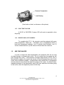
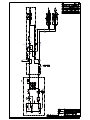
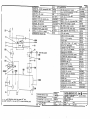
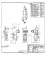
OPERATION AND SERVICE MANUAL
McGILL UNIVERSITY
PROJECT:
MCS-3237
SUBJECT:
HYDRAULIC POWER UNIT
AND ROTARY ACTUATORS
DECEMBER 2001
MCS-SERVO INC.
1950A, BOUL. MARIE-VICTORIN, ST-BRUNO-DE-MONTARVILLE, QUÉBEC, J3V 6B9
TEL: (450) 653-9465 / FAX: (450) 441-2527
www.mcs-servo.com / [email protected]
CONTENTS
1.
1.1.
1.2.
1.3.
1.4.
1.5.
1.6.
2.
2.1.
2.2.
2.3.
2.4.
3.
3.1.
3.2.
3.3.
DESCRIPTION OF HYDRAULIC COMPONENTS .................................................. 3
HYDRAULIC POWER UNIT ................................................................................. 3
HEAT EXCHANGER............................................................................................. 4
ACCUMULATOR MANIFOLD............................................................................... 5
ROTARY ACTUATORS........................................................................................ 5
FILTRATION......................................................................................................... 6
RECOMMENDED OIL .......................................................................................... 7
START-UP AND SYSTEM FLUSHING ................................................................... 8
PRELIMINARY INSPECTION............................................................................... 8
START-UP PROCEDURES.................................................................................. 9
SYSTEM FLUSHING ............................................................................................ 9
ADJUSTMENTS ................................................................................................. 12
MAINTENANCE AND REPAIR ............................................................................. 13
COMPONENT REPAIR ...................................................................................... 13
RECOMMENDED MAINTENANCE .................................................................... 14
TROUBLESHOOTING ....................................................................................... 16
4.
REPLACEMENT PARTS....................................................................................... 17
5.
HYDRAULIC SCHEMATICS ................................................................................. 19
6.
TECHNICAL INFORMATION ................................................................................ 23
2
MCS-SERVO INC.
1950A, BOUL. MARIE-VICTORIN, ST-BRUNO-DE-MONTARVILLE, QUÉBEC, J3V 6B9
TEL: (450) 653-9465 / FAX: (450) 441-2527
www.mcs-servo.com / [email protected]
1.
DESCRIPTION OF HYDRAULIC COMPONENTS
This section of the manual provides a brief description of the main
hydraulic components required for the proper functioning of the hydraulic system.
Additionally, you will find information regarding the functions and
adjustment parameters of the hydraulic components. Refer to section 6 of this
manual for a complete technical specifications listing.
1.1.
HYDRAULIC POWER UNIT
The hydraulic unit is required to operate the two new rotary actuators and
the existing one.
1.1.1. OIL RESERVOIR
The reservoir required has a capacity of 100 U.S. gallons of
hydraulic oil.
Two (2) access doors are located on each end the reservoir. One
(1) suction port is available for the hydraulic pump. There is one (1) “intank” style filter installed on the top of the reservoir.
1.1.2. HYDRAULIC PUMP
The hydraulic power unit has one hydraulic pump, variable flow and
pressure compensated type. It will vary the oil flow to keep a constant
pressure into the circuit. The pump has a capacity of 21 GPM (gallon per
minute) at 1800 RPM.
There are three adjustments available on the pump, which are the
load sensing, the compensator and the flow limiter. The first adjustment is
not used in your system configuration and SHOULD NOT BE MODIFIED.
The second adjustment has for function to control the system pressure. AT
ANY MOMENT, THE PUMPS’ PRESSURE SHOULD NOT BE UNDER
400 PSI. A pressure under this value will harm to the pump’s lubrication
and can damage it. The hydraulic circuit configuration requires a pressure
of 3000 PSI. The flow limiter has for function to limit the maximum flow
supplied by the pump. For your set-up, this adjustment SHOULD NOT BE
MODIFIED.
3
MCS-SERVO INC.
1950A, BOUL. MARIE-VICTORIN, ST-BRUNO-DE-MONTARVILLE, QUÉBEC, J3V 6B9
TEL: (450) 653-9465 / FAX: (450) 441-2527
www.mcs-servo.com / [email protected]
(flow limiter on back, not shown on this picture)
1.1.3. ELECTRIC MOTOR
A 40 HP at 1800 RPM, 3 phase, 600 volt motor is required to drive
the pump.
1.1.4. RESERVOIR ACCESSORIES
To complete the H.P.U., the reservoir must be equipped with some
other accessories. These are : a breather, one (1) temperature switch, a
level and temperature indicator, one (1) electric level indicator, one (1)
suction strainer and two (2) ball valves to fill and drain the reservoir.
1.2.
HEAT EXCHANGER
In order to extract the heat transmitted to the hydraulic fluid, the oil must
circulate through a oil/water type cooler. The oil coming from the return line will
pass through the cooler. If the pressure increases and reaches 30 PSI, due to
the restriction made by the cooler, the excess of flow will bypass the cooler by the
check valve installed in parallel. A thermostatic valve senses the oil temperature
into the reservoir and control the water flow going to the cooler. A solenoid valve,
installed upstream of the thermostatic valve, will close and block the water going
to the cooler, when the hydraulic power unit will stop.
4
MCS-SERVO INC.
1950A, BOUL. MARIE-VICTORIN, ST-BRUNO-DE-MONTARVILLE, QUÉBEC, J3V 6B9
TEL: (450) 653-9465 / FAX: (450) 441-2527
www.mcs-servo.com / [email protected]
1.3.
ACCUMULATOR MANIFOLD
To ensure a stable pressure, an accumulator is installed on the pressure
line. The accumulator manifold has a pressure relief valve and a dump valve.
The pressure relief valve’s function is to protect the circuit in case of too high
pressure. The dump valve is a normally opened solenoid valve, which is
energized when the hydraulic pump is turned on. If the pump is stopped, all the
pressure contained in the pressure line and the accumulator is dumped to the
reservoir. An orifice downstream the dump valve prevents shocks into the return
line by limiting the flow going to the reservoir. A pressure test point is available to
measure the supply pressure.
The diaphragm type accumulator is connected to the accumulator
manifold. The nitrogen pressure is 2400 PSI. It should be at approximately 80% of
the system pressure.
1.4.
ROTARY ACTUATORS
The actuators supplied are equipped with a Moog proportional valve, a
pressure reducing valve, a cam, a directional valve mechanically activated and a
potentiometer.
OBSOLETE
1.4.1. Moog proportional valve
The Moog D681-4718 is a proportional valve, 4 way, 10% overlap and
linear flow characteristic. The command signal is +/-10 Volts and the feedback is
+/-10 Volts with dead band compensation.
The valve’s electronics will
compensate for the 10% overlap of the spool. The valve is also equipped with an
electrical fail-safe.
In order to move the spool to the safe centered position, the two control
chambers of the main stage are hydraulically short circuited by a 4 way / 2
positions solenoid valve. The spring force move the spool into overlapped
centered position.
5
MCS-SERVO INC.
1950A, BOUL. MARIE-VICTORIN, ST-BRUNO-DE-MONTARVILLE, QUÉBEC, J3V 6B9
TEL: (450) 653-9465 / FAX: (450) 441-2527
www.mcs-servo.com / [email protected]
1.4.2. Pressure reducing valve
The pressure reducing valve can be used to reduce pressure downstream
of it. By reducing the pressure supplied to the actuator, the maximum torque
applied by the actuator is reduced. For maximal performances, the pressure
should be 3000 PSI.
1.4.3. Directional valve
The directional valve mechanically operated function is to block the
pressure going to the Moog proportional valve if it is activated by the cam.
1.4.4. Cam
The cam has been machined to allow a rotation of +/-20 degrees.
1.4.5. Potentiometer
The potentiometer has a 5K resistance and the theoretical electrical
travel is 340 degrees +/-5 deg.
1.5.
FILTRATION
The hydraulic system has two types of filtration. There are the high
pressure and the low pressure filters. All original filter assemblies are equipped
with filtration elements rated at 99.5% efficiency (ß3 ] 200).
The filters are equipped with electrical clogging indicators.
These
indicators can either be normally opened or normally closed. They give an
indication of the filtration elements condition. The indicators will shift when the
pressure differential between the inlet and the outlet exceeds approximately 116
PSI for the high pressure filter and 32 PSI for the low pressure filter. Generally,
when an indicator shifts the electrical logic, it means that the filter element needs
to be changed. However, when starting up during cold conditions, the oil has a
higher viscosity rating than it would during normal temperature operating
conditions. The higher viscosity rating could have the same effect on the
indicator as a clogged filter element. To avoid changing filter elements
6
MCS-SERVO INC.
1950A, BOUL. MARIE-VICTORIN, ST-BRUNO-DE-MONTARVILLE, QUÉBEC, J3V 6B9
TEL: (450) 653-9465 / FAX: (450) 441-2527
www.mcs-servo.com / [email protected]
unnecessarily, we recommend that the indicators be checked only when the
system reaches a normal operating temperature.
The return (or low pressure) filter is equipped with a bypass mechanism for
the filter element. This mechanism opens only when the pressure differential
pressure between the filter’s inlet and the outlet is 51 PSI. This is used to protect
the filter element against high pressure which could damage it or collapse it.
Even though the indicators seem to indicate that the filter elements are still
good, we strongly recommend to change the elements at regular intervals (e.g.,
during a regularly scheduled shut-down or approximately every 6 months).
1.5.1. HIGH PRESSURE FILTRATION
The high pressure filter is installed at the pump’s outlet and is “nonbypass” type. It features a 3000 PSI collapse rating which will eliminate all
possible contamination risks downstream the filter. The element is rated at
3 micron absolute (ß3 ] 200).
1.5.2. LOW PRESSURE FILTRATION
The low pressure filter is installed on the H.P.U.. It has a bypass
valve prevent back-pressure in the return line which could damage the
filtration element. The element is rated at 3 micron absolute (ß3 ] 200).
1.6.
RECOMMENDED OIL
There are several types of oil available on the market. That which concerns
us is oil designed for hydraulic systems. In this category, oils are classified
according to their viscosity and the additives contained therein. For your hydraulic
system, we recommend Shell Tellus 32, Tribospec Corporation’s Sunvis 700, or
all equivalent oils.
Because of certain components construction and precision machining of
internal parts, the system’s oil must be maintained at a certain cleanliness level.
According to ISO code DIS 4406 (SAE J1165), Moog recommends ISO
cleanliness level of 14/11 (or better) with a maximum of 16/13 for all servovalves
and proportional valves. Hydraforce recommends a cleanliness level of ISO code
18/14 for its cartridge valves. ISO code 14/11, being the most stringent of the
hydraulic system, is therefore the cleanliness level to be maintained in order to
maximise both system performance and component life. The efficiency level of
the hydraulic system is directly linked to the overall performance.
7
MCS-SERVO INC.
1950A, BOUL. MARIE-VICTORIN, ST-BRUNO-DE-MONTARVILLE, QUÉBEC, J3V 6B9
TEL: (450) 653-9465 / FAX: (450) 441-2527
www.mcs-servo.com / [email protected]
2.
START-UP AND SYSTEM FLUSHING
The recommendations which follow concern the start-up procedure. This
procedure must be followed after every prolonged system shut-down and
especially following repairs to the system.
2.1.
PRELIMINARY INSPECTION
Prior to engaging the electric motor:
- Check fluid level in the reservoir. The level must be near the upper limit of the
level indicator. Top up, if necessary, with clean and filtered fluid (the use of a
portable filtration unit, available at MCS-SERVO INC., is strongly
recommended).
- Verify that pump housing is filled with fluid. Unscrew the upper-most fitting on
the pump. If required, fill with clean fluid.
- If the pump has been repaired or replaced, make sure that it has been properly
mounted on the electric motor, that all connections have been tightened, and
that the pressure compensator screw has been properly adjusted.
- Check accumulator precharge pressure. It should be approximately 2400 PSI.
Use a charging unit (available at MCS-SERVO INC.).
- If a component has been removed for repair or replacement, ensure that it has
been properly reinstalled according to schematic specifications, material lists,
or to specific mounting instructions.
- If a hydraulic line has been disconnected, ensure that it has been correctly
reinstalled according to specifications or to proper installation procedure.
8
MCS-SERVO INC.
1950A, BOUL. MARIE-VICTORIN, ST-BRUNO-DE-MONTARVILLE, QUÉBEC, J3V 6B9
TEL: (450) 653-9465 / FAX: (450) 441-2527
www.mcs-servo.com / [email protected]
2.2.
START-UP PROCEDURES
NOTE : Read section 2.3 if a flushing is required for a part of the system or
section 2.4 for the whole system if some components requires settings.
Connect the 0-3000 PSI gauges to the test points located on the
accumulator manifold. Start the electric motor.
-
If work has been carried out on the motors' electric line, verify its rotation.
Remove the plastic cover located on the pump/motor adapter and, using a
marker, indicate the direction of rotation. Effect short "start-stop" sequences
to confirm motor rotation. For a pump with a clock-wise rotation, the motor's
rotation will usually be the opposite (i.e., counter-clockwise). A pump's rotation
must always be checked with the shaft facing the technician. If required, the
motor's rotation may be changed by inverting the two wires in the feed cable
(check rotation again). Replace plastic cover.
-
Re-initiate short "start-stop" sequences to charge the pump. Check for fluid
leaks and/or unusual noises and correct as required. Also check the gauge's
needle. The pump must operate smoothly under stable pressure after
charging.
-
Pay particular attention to start-ups effected under cold conditions : Cold fluids
are very viscous and could cause premature pump wear or breakdown. Startups are not recommended when system fluid temperature is inferior to 10 °C
(50 °F).
-
Keep watch of the reservoir's fluid level. Fill as required with clean and filtered
fluid (see section 2.1).
2.3.
SYSTEM FLUSHING
A system flushing is required if a repair is made on a hydraulic component
located upstream a sensitive component to the contamination which there can be
in oil. A premature start-up without proper flushing could lead to costly repairs as
well as a loss of production time.
While most major fluid suppliers offer specially-designed fluids exclusively
for hydraulic system flushing, standard system fluid may be used for flushing so
9
MCS-SERVO INC.
1950A, BOUL. MARIE-VICTORIN, ST-BRUNO-DE-MONTARVILLE, QUÉBEC, J3V 6B9
TEL: (450) 653-9465 / FAX: (450) 441-2527
www.mcs-servo.com / [email protected]
long as it is initially clean. Best results are achieved when the system fluid
temperature is high and the flow is turbulent.
2.3.1. PREPARATION FOR SYSTEM FLUSHING
While a system flushing is a procedure which requires a certain
amount of preparation, it plays an important role in ensuring prolonged life
for the implicated components. If the flushing procedure is improperly
carried out or ignored, components in the hydraulic circuit may become
damaged.
The following are the recommended steps to follow for a proper flushing:
1) Install a flushing element in the high pressure filter assembly. We
suggest elements rated at 3 microns absolute.
2) Replace the return line filter element with new element. Again, We
suggest elements rated at 3 microns absolute.
3) Isolate all proportional valves in the circuit being rinsed. This may be
achieved by any of the following methods :
a)
Replacing
the
proportional
valves
by
directional
valves;
b) Replacing the proportional valves by specially-designed rinsing
plates;
Note : We suggest that the proportional valves be properly stored in
sealed plastic bags whenever removed from their manifolds.
c) Linking the pressure (P) line to the return line (T) leading to the
manifolds of the particular valve to be isolated.
4) Heat the reservoir oil to approximately 50 °C (122 °F) if required. To do
so, follow the instructions as listed in 3). If option 3a) has been
undertaken, then proceed according to 4a) – if not, proceed according
to 4b).
a) Start the pump and adjust the pumps’ compensator to
approximately 500 PSI (see the notes lower). Activate each of the
directional valves so as to ensure proper circulation of the oil in
the circuit. Leave circulate for about 1.5 to 2 hours.
10
MCS-SERVO INC.
1950A, BOUL. MARIE-VICTORIN, ST-BRUNO-DE-MONTARVILLE, QUÉBEC, J3V 6B9
TEL: (450) 653-9465 / FAX: (450) 441-2527
www.mcs-servo.com / [email protected]
b) Close the pressure ball valve at pump outlet as well as the one at
the low pressure filter’s inlet. Adjust the pump compensators to
approximately 500 PSI. Completely open the pressure valve first.
Then, slowly open the return valve until the pressure equals the
pump’s pressure or until the pump starts to “grumble”. In the case
of the latter condition, close the return valve until the pump begins
to operate normally. Leave circulate for about 1.5 to 2 hours.
Notes : - It is important to reduce system pressure to approximately
500 PSI to reduce the possibility pressure spikes in the
system and to avoid damaging the rinsing elements;
- Regularly verify the pump’s pressure because, as the oil
temperature rises, viscosity diminishes therefore causing
pressure to drop. The pump’s pressure should never go
under 400 PSI under risk to damage the pump;
- Regularly check oil level in the reservoir if a major
intervention occurred in the system and a large quantity of
air has been introduced in the piping. Add clean oil as
required.
5) Stop the system and allow the oil to cool.
6) Change rinsing element for a new high pressure filter element (see
section 4).
7) Change the return filter element (low pressure) for new filter element
(see section 4).
8) Re-install the proportional valves or reconnect the hoses to their original
positions.
9) Completely open the return line ball valve and completely close the ball
valve on the pressure line.
10) Re-start the pump and re-adjust the pump compensator to its original
value.
11) Slowly open the pressure line ball valve to pressurize the system.
12) Re-verify reservoir oil level.
11
MCS-SERVO INC.
1950A, BOUL. MARIE-VICTORIN, ST-BRUNO-DE-MONTARVILLE, QUÉBEC, J3V 6B9
TEL: (450) 653-9465 / FAX: (450) 441-2527
www.mcs-servo.com / [email protected]
Note : It is important to keep all affected areas, components, and
personnel involved with the flushing as clean as possible. It is
imperative to undertake all possible precautions to avoid
contaminating the components or the hydraulic circuit with foreign
particles or with liquid other than the hydraulic fluid being utilised.
2.4.
ADJUSTMENTS
The hydraulic system uses some components that requires adjustments
(like pressure, flow and temperature) and those adjustments can be modified to
obtain the best system’s performances. The hydraulic system can be considered
as a prototype during the start up. The following adjustments are suggested to
obtain good performances. However, during start up, some re-adjustments should
be necessary. Refer to section 5 for parts listing and section 6 for all technical
details.
2.4.1. ADJUSTABLE COMPONENTS ON THE H.P.U.
Components featuring adjustments on the hydraulic power unit
(H.P.U.) are the pump’s compensator, the temperature switch, the relief
valve and the thermostatic valve.
2.4.1.1. PUMP’S COMPENSATOR ADJUSTMENT
On the pressure compensated pump, two adjustments are
possible. One adjustment is the maximum flow that the pump can
supply while and the other is the system pressure (see section
1.1.2).
- Pump pressure compensator :
This is used to limit the system pressure. For ideal system
performance, the pressure compensator must adjusted at 300 PSI.
The maximum pressure adjustment can be up to 4000 PSI.
- Pump flow limiter :
This is used to limit the flow supplied to the system. This
adjustment requires the use of a flow meter. This adjustment must
therefore be carried out by qualified personnel using the proper
12
MCS-SERVO INC.
1950A, BOUL. MARIE-VICTORIN, ST-BRUNO-DE-MONTARVILLE, QUÉBEC, J3V 6B9
TEL: (450) 653-9465 / FAX: (450) 441-2527
www.mcs-servo.com / [email protected]
equipment. Consequently, this adjustment must not be modified
(original adjustment).
2.4.1.2. TEMPERATURE SWITCH
There is one temperature switch installed on the reservoir. It
should be set at 65 °C (150 °F). Its function is to shut down the
hydraulic system in order to avoid causing damage to the circuit’s
components due to over-heating problem.
2.4.1.3. THERMOSTATIC VALVE
The thermostatic valve regulates the water flow going
through the oil cooler. It can be adjusted between 1 and 5 which
corresponds to the opening temperature to allow the water going to
the cooler. The numbers 1 is equivalent to 25 °C (77 °F) and 5 is
equivalent to 65 °C (150 °F). The valve is set at 3 (110 °F).
3.
MAINTENANCE AND REPAIR
The trouble-free functioning of a hydraulic system begins with proper
maintenance and adequate repair of system components when required.
However, as is true with all machines, some components may break down without
notice. System performance may be severely compromised due to improper use
or incorrect settings. Section 3.3 describes some of the most common problems
that may occur in the hydraulic system.
3.1.
COMPONENT REPAIR
Some components (e.g., reservoir accessories, cartridge valves, other
standard valves, strainers, etc.), because of their relatively low cost, may not be
economically repairable.
Other components, such as accumulators, oil coolers, filter heads, and
flow regulators are not prone to breakdown if they are used under normal
operating conditions.
Even such components such as pumps, solenoid valves, servovalves and
cylinders should be replaced by new units in case of breakdown in order to
13
MCS-SERVO INC.
1950A, BOUL. MARIE-VICTORIN, ST-BRUNO-DE-MONTARVILLE, QUÉBEC, J3V 6B9
TEL: (450) 653-9465 / FAX: (450) 441-2527
www.mcs-servo.com / [email protected]
reduce down-time. By using this strategy, the defective units may be repaired and
subsequently be used as spares.
Section 6 provides a detailed description of these components along with
the related technical information required to repair the defective parts. Section 4
provides a partial list of the most commonly required replacement parts. The
manufacturer recommends that these parts should be kept in stock as their failure
is one of the major causes of system stoppages.
The repair and reconditioning of the majority of the system's components
must be undertaken by qualified technicians in a clean and well equipped
environment designed for that purpose. If your personnel does not have these
qualifications, it is recommended that the components be forwarded to a
hydraulics specialist (i.e., MCS-SERVO INC.).
3.2.
RECOMMENDED MAINTENANCE
The principle source of system stoppages in hydraulic systems is dirt (e.g.,
dust) and most particularly fluid contamination. A clean system operating in a
clean environment will function for longer periods of time with greater
performance and efficiency.
Therefore :
- Change filter elements regularly (e.g., every 2000 hours of
operation or once par year) or when notified by the status of filter
indicators. Even though changing elements may require that the
system be shut down, the little time this action take could very well
save hours or even days of down time caused by contaminated
pumps or servovalves.
Note : During cold condition start-ups, filter indicators may indicate that the elements
are obstructed. This is caused, however, by the fluid's high viscosity. The filter
indicators must therefore only by considered when fluid temperature nears
normal operating levels (30 °C).
- Keep the system clean. Do not allow dust or foreign materials to
accumulate on components or hoses and most particularly on the
top of reservoirs in which particles may fall into during inspections
or opening of the breather cap. Stop leaks as soon as they are
detected. Not only will leaks cause fluid loss, but dust particles will
14
MCS-SERVO INC.
1950A, BOUL. MARIE-VICTORIN, ST-BRUNO-DE-MONTARVILLE, QUÉBEC, J3V 6B9
TEL: (450) 653-9465 / FAX: (450) 441-2527
www.mcs-servo.com / [email protected]
also be introduced into the system. Problems may be more easily
pin-pointed and solved when a system is kept clean.
- If the system's environment is excessively dirty, precise measures
must be taken to prevent dirt from accumulating and gaining
access to the system through the breather cap.
- Two other major causes of hydraulic system shut-down or loss of
performance are excessive fluid temperatures and insufficient fluid
levels in the reservoir.
- Do not allow the system to operate at an excessively high
temperature (e.g., greater than 65 °C (150 °F)). High temperatures
lead to the following problems : Low fluid viscosity and degradation,
an increase in internal leaks, acceleration of component wear,
reduction in the joints' useful operating life, modification of valve
function, etc. It is important to locate problems and to correct them
immediately.
We also recommend to daily check the following points. This will enable
you to make a certain preventive maintenance on the machine.
- An inspection of the reservoir (for any openings on the surface);
- A cursory inspection of all manifold hoses and tubing for any apparent leaks;
- List any and all abnormal noises, shocks or vibrations in the conduits;
- Make a report of all mechanical problems (e.g., excessive friction, jerky or
abrupt movements, etc.).
As was mentioned in section 2.3, a complete system flushing should be
undertaken after a stoppage caused by the breakdown of a component. A partial
flushing is sufficient if the breakdown occurs past the component's protection
filter.
A complete system cleaning and flushing should be undertaken at least
once per year. Carefully inspect and clean all components and repair or replace
any defective part to keep the system functioning at perk performance levels.
15
MCS-SERVO INC.
1950A, BOUL. MARIE-VICTORIN, ST-BRUNO-DE-MONTARVILLE, QUÉBEC, J3V 6B9
TEL: (450) 653-9465 / FAX: (450) 441-2527
www.mcs-servo.com / [email protected]
3.3.
TROUBLESHOOTING
This section lists the major causes of the most frequently
encountered hydraulic system breakdown problems (consult a hydraulics
specialist, e.g., MCS-SERVO INC., for problems not listed below). The first step
in diagnosing any system problem is to start looking for the furthest point up the
line (from the pump) where it is known that the system is functioning properly.
Afterwards, follow the flow's direction and effect a component-by-component
check until the faulty part is located.
ABSENCE OF FLOW:
- The electric motor(s) is (are) not functioning;
- The pump is not coupled to the electric motor;
- Fluid level is low;
- The pump is not primed;
- The pump is defective;
- The flow regulating valve(s) on the manifold is (are) not completely
open or closed.
FLOW IS WEAK:
- The pump is defective;
- A component of the hydraulic circuit leaks.
ABSENCE OF PRESSURE:
- Absence of flow (see above);
- The pump is defective;
- The pressure regulating valve is either completely open or adjusted
too close to the recommended minimum pressure.
LOW PRESSURE:
- The pressure compensator's adjustment is too low;
- The pump is defective;
- The pressure regulating valve is either adjusted too low or partially
open.
NOISY OPERATION:
- Fluid temperature is too low (cavitation);
- Breather is obstructed (cavitation);
- Strainer is obstructed (cavitation);
16
MCS-SERVO INC.
1950A, BOUL. MARIE-VICTORIN, ST-BRUNO-DE-MONTARVILLE, QUÉBEC, J3V 6B9
TEL: (450) 653-9465 / FAX: (450) 441-2527
www.mcs-servo.com / [email protected]
Pump suction valve is partially closed (cavitation);
Fluid level in reservoir is too low (aeration);
Connections improperly fastened on the suction line (aeration);
Pump is worn;
Couplings worn or improperly fastened;
Incorrect pump rotation;
The pressure regulating valve is adjusted lower than the pump
pressure compensator setting;
- Pressure regulating valve and pressure compensator settings have
near or similar values;
-
SYSTEM OVERHEATING:
- The heat exchanger is blocked;
- The oil does not circulate in the cooler;
- The cooler fan is either blocked or is turning in the wrong direction;
- Heat exchanger intake air is too hot;
- The cooler's starter switch is set to high;
- The temperature probe is not in the reservoir;
- Ambient air temperature is too high;
- Fluid level is too low;
- Cavitation or excessive aeration (see "NOISY OPERATION");
- The pressure regulating valve is set below the pump's pressure
compensator setting;
- Excessive fluid leaks aft of the system components.
4.
REPLACEMENT PARTS
A comprehensive inventory of replacement parts may initially seem to be
an excessive expense... until a problem arises. Stocking replacement parts can,
therefore, facilitate repairs and decrease downtime due to long delivery delays for
certain components. This investment can pay for itself, by decreasing downtime,
after as little as one repair.
The table, following on the next pages, indicates for each important parts
its location on the machine, its importance in the event of breaking, the standard
delivery time and the quantities which we suggest having in stock.
17
MCS-SERVO INC.
1950A, BOUL. MARIE-VICTORIN, ST-BRUNO-DE-MONTARVILLE, QUÉBEC, J3V 6B9
TEL: (450) 653-9465 / FAX: (450) 441-2527
www.mcs-servo.com / [email protected]
Part number
Description
Sugg. quantities
BEPI2230
BEPI2130
BEPI21040RN
6366115
SV10-21-0-N-00
SV16-20-0-N-00
CV16-20-0-N-05
RV50-22A-0-P-50
LS1800-01801
4WMR10C3X
PBFB-LAN
112P1952
High pressure element 3 microns
Flushing element for high pressure filter
Return filter element 3 microns
Coil for Hydraforce solenoid valve
Hydraforce solenoid valve
Hydraforce solenoid valve
Hydraforce check valve
Hydraforce relief valve
Electrical level switch
Directional valve
Pressure reducing valve
Potentiometer 5K
1
1
1
1
1
1
1
1
1
1
1
1
18
MCS-SERVO INC.
1950A, BOUL. MARIE-VICTORIN, ST-BRUNO-DE-MONTARVILLE, QUÉBEC, J3V 6B9
TEL: (450) 653-9465 / FAX: (450) 441-2527
www.mcs-servo.com / [email protected]
5.
HYDRAULIC SCHEMATICS
19
MCS-SERVO INC.
1950A, BOUL. MARIE-VICTORIN, ST-BRUNO-DE-MONTARVILLE, QUÉBEC, J3V 6B9
TEL: (450) 653-9465 / FAX: (450) 441-2527
www.mcs-servo.com / [email protected]
HP020
FWD
Flow 1
Pressure
Valve-X
FWD
Flow 2
OBSOLETE
6.
TECHNICAL INFORMATION
In this section, you will find all the information about the important parts and
components of the hydraulic circuit.
23
MCS-SERVO INC.
1950A, BOUL. MARIE-VICTORIN, ST-BRUNO-DE-MONTARVILLE, QUÉBEC, J3V 6B9
TEL: (450) 653-9465 / FAX: (450) 441-2527
www.mcs-servo.com / [email protected]