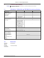
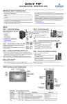
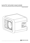
1
Instruction Manual
Reference Resistor Kit 1 Ω, 100 Ω, 1 kΩ
for TOE 9260 Electronic Switch
TOE 9260/100
9260E-Opt100-Manual-Rev01.doc
R
TOELLNER ELECTRONIC INSTRUMENTE GMBH
Gahlenfeldstraße 31, 58313 Herdecke, Germany
+49 (0) 23 30 - 97 91 91 • Fax +49 (0) 23 30 - 97 91 97
E-Mail: [email protected] • Web: www.toellner.de
Subject to technical changes
TOELLNER Electronic Instrumente GmbH
06.11.2014
Contents
2
Page
1.
Introduction .............................................................................................................3
1.1
Features ................................................................................................................................ 3
2.
Operation .................................................................................................................4
2.1
2.1.1
2.2
2.2.1
2.2.2
2.3
2.4
2.4.1
2.4.2
Startup ................................................................................................................................... 4
Installation and ventilation .................................................................................................. 4
Description of the controls ..................................................................................................... 4
TOE 9260/101, TOE 9260/102, and TOE 9260/103 front panel controls............................ 4
TOE 9260/101, TOE 9260/102, and TOE 9260/103 rear panel controls ............................ 4
Device operation ................................................................................................................... 5
Protection .............................................................................................................................. 6
Excessive temperature protection ...................................................................................... 6
Overvoltage and overcurrent protection.............................................................................. 6
3.
Technical Specifications ........................................................................................7
3.1
3.2
TOE 9260/101, TOE 9260/102, and TOE 9260/103 technical specifications ........................ 7
General data.......................................................................................................................... 7
4.
Views ........................................................................................................................8
TOELLNER Electronic Instrumente GmbH
Section 1 – Introduction
1.
Introduction
The TOE 9260/100 Reference Resistor Kit for the TOE 9260 Electronic Switch is intended
for performing reference measurements according to the automotive test standard
LV 124 ‒ 2013. It consists of three units TOE 9260/101, TOE 9260/102, and TOE 9260/103.
The TOE 9260/101 is a low-inductive power resistor 1 Ω / 144 W for short-term operation at
a voltage of up to 12 V.
The TOE 9260/102 is a low-inductive power resistor 100 Ω / 36 W for operation at a voltage
of up to 60 V.
The TOE 9260/102 is a low-inductive resistor 1 kΩ / 3.6 W for operation at a voltage of up to
60 V.
1.1
Features
-
Low series inductance
5% resistance tolerance
Thermal overload protection and overcurrent lead fuse for the 1 Ω resistor
Thermal overload protection for the 100 Ω resistor
Dedicated input plugs matching the output sockets of the power switch of the TOE 9260
Electronic Switch
- BNC output for connection to measurement equipment
TOELLNER Electronic Instrumente GmbH
3
Section 2 – Operation
2.
Operation
2.1
Startup
Warning
Safe operation of these devices presumes that they have been placed in service properly
by qualified personnel in compliance with the warnings in this manual.
In particular the general installation and safety regulations (e.g. DIN/EN and VDE) must be
observed. Non-observance may result in personal injury or damage to equipment.
Ensure that only fuses of the specified type and specified current are used as
replacements (→ 3.1 TOE 9260/101, TOE 9260/102, and TOE 9260/103 Technical
Specifications, → rating plates). The use of repaired fuses or short-circuiting the fuse
holder is not permitted.
If it is apparent that non-hazardous operation is no longer possible, the devices must be
taken out of service and secured against unintended operation.
2.1.1
Installation and ventilation
There are no problems associated with installation of these devices.
The TOE 9260/101 and TOE 9260/102 use vents in the housing for heat dissipation. Provide
sufficient ventilation distance so that the vents can work effectively. Otherwise it can happen
that under high load conditions the unit will heat up to a point where it is automatically shut
off (→ 2.4.1 Excessive temperature protection).
For the TOE 9260/103, no ventilation is needed because of the small power dissipation.
2.2
Description of the controls
At the end of the manual you will find the operating elements for the TOE 9260/101,
TOE 9260/102, and TOE 9260/103 numbered with front panel and rear views. The individual
operating elements are explained in detail below.
2.2.1
[1]
TOE 9260/101 only: Lead TAC blade fuse 10 A / 58 V. Suitable replacement part is
Littelfuse, type TAC ATO style blade fuse, rated 58 V.
This fuse prevents damage from the power resistor of the TOE 9260/101 unit in case
of an excessive operating voltage, i.e. when the thermal protection inside the
TOE 9260/101 cannot be triggered fast enough anymore. The 58 V rating is
necessary for the breaking capability at excessive operating voltages.
The 10 A rated current value is the suitable value for short-term operation at up to at
least 12 A, which is the resulting current when the TOE 9260/101 is operated at its
rated voltage. To retain protection of the power resistor, a fuse of higher rated current
value must not be inserted.
[2]
BNC output for measuring the voltage across the reference resistor during switching
operation. This socket is internally connected to the reference resistor via a 50 Ω
series resistance.
2.2.2
[3]
4
TOE 9260/101, TOE 9260/102, and TOE 9260/103 front panel controls
TOE 9260/101, TOE 9260/102, and TOE 9260/103 rear panel controls
These plugs are used to connect the unit to the output socket pair of the TOE 9260
Electronic Switch. The polarity is indicated by plus and minus signs in the housing of
the unit.
TOELLNER Electronic Instrumente GmbH
Section 2 – Operation
2.3
Device operation
The TOE 9260/101, TOE 9260/102, and TOE 9260/103 units are intended for performing
reference measurements according to the LV 124 ‒ 2013 standard by use of the power
switch of the TOE 9260 Electronic Switch.
Applicable LV 124 ‒ 2013 tests are as follows:
•
E-10, Short Interruptions
•
E-13, Pin Interruption
To perform a reference measurement, the input of the TOE 9260 must be connected to a DC
voltage of 11 V in the case of test E-10 or 12 V in the case of test E-13. This voltage can be
supplied by a power supply or by a specific control device which is intended for use as the
signal generator for an E-13 test. The polarity and current flow direction of the power switch
of the TOE 9260 must be observed. If applicable, the input buffer capacitor of the TOE 9260
can be activated by setting the appropriate DIL switch to the ON position. Without such
buffering of the input, the input cable inductance must meet a value of max. 250 nH, which
can be achieved by a reduced cable length of max. 300 mm and twisted laying of the cable.
The reference resistor TOE 9260/101, TOE 9260/102, or TOE 9260/103 is connected to the
output of the TOE 9260. A suitable pulse waveform must be applied to the control input of
the TOE 9260.
For evaluation of the rise and fall times of the switching operations, the BNC output of the
reference resistor unit must be connected to an oscilloscope by a 50 Ω BNC cable as
follows:
In the case of the TOE 9260/101, the connection may be established either with or without a
terminating resistor of 50 Ω at the input of the oscilloscope.
In the case of the TOE 9260/102 or TOE 9260/103, the connection must only be established
without a 50 Ω termination at the end of the BNC cable, i.e. the cable must be connected to
a high impedance input of an oscilloscope, usually 1 MΩ.
Note
A 50 Ω terminating resistor at the BNC cable or the input of the oscilloscope must not be
applied in the case of the TOE 9260/102 or TOE 9260/103, because otherwise the
reference resistor would be reduced by a parallel resistance, and the measurement would
not be in line with the LV 124 standard anymore.
Please note that the power dissipation of the TOE 9260/101 depends on the high/low time
ratio of the applied waveform. When operated continuously at 12 V, short-term operation of
approx. 25 s is possible. This is a rough guidance value only, because the reachable
operation time depends both on the initial temperature of the TOE 9260/101 and the ambient
temperature. When the maximum permissible operation temperature is reached, the
TOE 9260/101 interrupts the current flow by triggering an internal reversible circuit breaker.
The unit can be restarted after a sufficient cooling down time.
The TOE 9260/102 is thermally protected in the same way, but operation at even up to 60 V
is much less time-critical because of the much lower power dissipation of the 100 Ω
reference resistor.
The TOE 9260/103 has no thermal protection because it can be operated continuously at up
to 60 V due to the small power dissipation.
The lead fuse of the TOE 9260/101 is triggered only when an excessive overvoltage is
applied to the unit, so that the thermal protection inside the TOE 9260/101 cannot be
triggered fast enough anymore to prevent damage from the power resistor. A suitable
replacement part is Littelfuse, type TAC ATO style blade fuse, rated 58 V. The 58 V rating is
necessary for the breaking capability at excessive operating voltages.
Note
The 10 A rated current value of the lead fuse is the suitable value for short-term operation
at up to at least 12 A, which is the resulting current when the TOE 9260/101 is operated at
its rated voltage. To retain protection of the power resistor, a fuse of higher rated current
value must not be inserted.
TOELLNER Electronic Instrumente GmbH
5
Section 2 – Operation
2.4
Protection
2.4.1
Excessive temperature protection
The TOE 9260/101 and TOE 9260/102 are protected against excessive temperatures by a
reversible thermal circuit breaker. In the case of triggering of this protection device, the unit
can be restarted after a sufficient cooling down time.
The TOE 9260/103 does not need a thermal protection because of its small power
dissipation.
For further details please refer to the operation section (→ 2.3 Device operation).
2.4.2
Overvoltage and overcurrent protection
The TOE 9260/101 is protected against an overvoltage leading to a high operation current by
a lead fuse. This protection covers overvoltages of up to 58 V.
The TOE 9260/102 and TOE 9260/103 have no overvoltage protection because operation at
up to 60 V is permissible.
6
TOELLNER Electronic Instrumente GmbH
Section 3 – Technical Specifications
3.
Technical Specifications
Remark
3.1
The technical specifications are based on constant conditions and a reference
temperature of 23°C ±1°C.
TOE 9260/101, TOE 9260/102, and TOE 9260/103 technical specifications
Device
Characteristics
Reference resistor value
Resistance tolerance
Rated voltage
Rated power
Protection functions
Excessive temperature
Overvoltage
Connections
Input connector
Measurement output
TOE 9260/101
TOE 9260/102
TOE 9260/103
1Ω
± 5%
12 V
144 W
short-term operation,
approx. 25 s
100 Ω
± 5%
60 V
36 W
1 kΩ
± 5%
60 V
3.6 W
Reversible thermal circuit breaker
10 A / 58 V lead TAC
blade fuse. Suitable
replacement part is
Littelfuse, type TAC ATO
style blade fuse, rated
58 V.
For details on current and
voltage rating of this fuse,
please refer to the
operation section
(→ 2.3 Device operation)
--
Dedicated plug pair for connection to output of TOE 9260 Electronic Switch
BNC output for use with or
BNC output for use without termination
without 50 Ω termination
General
Degree of protection
Operating temperature
Storage temperature
Reference temperature
Cooling
Dimensions (W x H x D)
Weight
Housing
3.2
General data
Ordering
options
TOE 9260/100
Included
accessories
1 Instruction Manual
TOELLNER Electronic Instrumente GmbH
--
IP20 according to IEC 60529
0 – 40 °C
−20 – 70 °C
23 °C ±1 °C
Vents
48 mm x 64 mm x 129 mm
Approx. 300 g
Aluminium
7
Section 4 – Views
4.
Views
Front panel view of TOE 9260/101, TOE 9260/102, TOE 9260/103
[1] Fuse 10 A
[2] BNC output
Rear view of TOE 9260/101, TOE 9260/102, TOE 9260/103
[3] Input plug pair
8
TOELLNER Electronic Instrumente GmbH