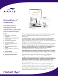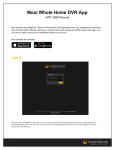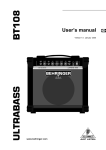
1
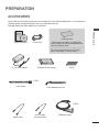
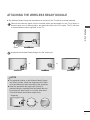
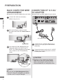
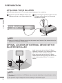
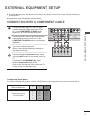
OWNER’S MANUAL
WIRELESS MEDIA BOX
Please read this manual carefully before operating
your set and retain it for future reference.
www.lg.com
CONTENTS
Preparation
CONTENTS
Accessories..........................................................3
Front panel controls.............................................4
BACK PANEL INFORMATION.............................5
Side panel INFORMATION..................................5
Wireless Ready Dongle.......................................6
Connecting to the TV............................................6
Attaching the Wireless Ready Dongle.................7
Back Cover for Wire Arrangement.......................8
Connection of 12 V AC/DC Adapter.....................8
Optimal Installation Location of Wireless Media
Box.......................................................................9
Reception Problems due to interference.............9
Attaching the IR blaster......................................10
Optimal location of external device with IR
Blaster installed..................................................10
Watching TV / Program control
Turning on the Wireless Media box...................17
Input list..............................................................18
IR Blaster Setup.................................................18
appendix
IR Code List.......................................................19
RF Specifications...............................................20
Frequency Table.................................................21
Product Specifications........................................22
Troubleshooting..................................................22
external equipment setup
Connecting with a Component cable.................11
Connecting with an HDMI cable........................12
Connecting with an HDMI to DVI cable.............13
Connecting with RCA cable...............................14
Digital Audio Out Setup......................................15
Connecting with RGB.........................................15
Supported Display Resolution............................16
Indoor use only
This device only works with compatible
Wireless Ready LG LCD, LED LCD, and
Plasma TVs.
This product does not support 3D.
Except for USA
Manufactured under license from Dolby Laboratories.
Dolby and the double-D symbol are trademarks of
Dolby Laboratories.
2
Preparation
Accessories
Ensure that the following accessories are included with your Wireless Media Box. If an accessory is
missing, please contact the dealer where you purchased the set.
■ Image shown may differ slightly from your device.
Owner’s Manual
Power Cord
* Lightly wipe any stains or fingerprints
on the surface of the Wireless Media Box
with the polishing cloth.
preparation
Polishing Cloth
Do not use excessive force. This may
cause scratching or discolouration.
12 V AC/DC Adapter
Velcro
Wireless Ready Dongle
X 2EA
Cable Holder
Cable Management Clip
X 2EA
HDMI Cable
20 Pin Cable
(Power/Control)
IR Blaster Cable
3
preparation
Front panel controls
NOTE
preparation
►►This product is only for home use.
►►Do not use this product in medical institutions or near medical devices. It may cause some medical devices to malfunction.
►►Wireless device used to this instrument could be set up and used only to this instrument.
►When
►
using the external device connected to the Wireless Media Box, some functions of the TV
menu may not work.
■ Image shown may differ slightly from your device.
2
1
AV1
AV2
COM1
COM2
RGB
HDMI1
HDMI2
HDMI3
HDMI4
3
WIRELESS
1
Input Source Indicator & INPUT touch button
Select the input source by touching.
2
Wireless Connection Indicator
It will flash when trying to connect to a wireless network and be turned on when
connected.
3
power touch button
Turn the Wireless Media Box on or off by touching.
AV INnot
1
A COMPONENT
If the /AI (Power) button of
Box /is
turned on, the
B the Wireless Media
B COMPONENT / AV IN 2
AUDIO IN
Wireless Media Box will not be turned on even when
turn on the power of the TV.
2
1
If the Wireless Media Box is 3not turned
on RGB
even
after turning the power of the TV
IN (PC)
on, check the / I (Power) button of the Wireless Media Box.
LR
DC IN 12V
4
OPTICAL DIGITAL
AUDIO OUT
L(MONO) AUDIO R
SERVICE ONLY
LR
VIDEO
IR BLASTER
VIDEO
L(MONO) AUDIO R
/ DVI IN
RGB/DVI
SERVICE ONLY
Power/Standby Indicator
Illuminates red in standby mode.
Illuminates white when the Wireless Media Box is switched on.
* ID Label of Wireless Media Box is located at the bottom of Wireless Media Box.
4
4
BACK PANEL INFORMATION
■ Image shown may differ slightly from your device.
1
LR
AV1
COM1
COM2
B HDMI2
HDMI1
RGB
L(MONO) AUDIO R
VIDEO
LR
HDMI3
3
OPTICAL DIGITAL
AUDIO OUT
2
5
4
6
Component Input
Connect a component video/audio device to
these jacks.
Audio/Video Input(AV1/2)
Connect audio/video output from an external
A COMPONENT / AV IN 1
device
to these jacks.
A
B
B
1
LR
3
3
4
DC IN 12V
OPTICAL DIGITAL
AUDIO OUT
SERVICE ONLY
COMPONENT / AV IN 2
L(MONO) AUDIO R
2
/ DVI IN
AUDIO IN
1
RGB IN (PC)
RGB/DVI
RGB IN (PC)
RGB/DVI
SERVICE ONLY
7
8
5
SERVICE ONLY PORT
HDMI/DVI IN Input
Digital Connection. Supports HD video and
Digital audio. Doesn’t support 480i. Accepts
DVI video using an adapter or HDMI to DVI
cable (not included).
6
LR
VIDEO
L(MONO) AUDIO R
IR Blaster
Controls external equipment.
2
5
IR BLASTER
VIDEO
AUDIO IN
1
/ DVI IN
SERVICE ONLY
A COMPONENT / AV IN 1
B COMPONENT / AV IN 2
WIRELESS
L(MONO) AUDIO R
3
DC IN 12V
HDMI4
preparation
VIDEO
AV2
IR BLASTER
A
2
SERVICE ONLY
DC IN 12 V Power Cord Socket
This Wireless Media Box operates on 12 V
DC power. Only use a power converter that
the device was designed to use.
7 RGB IN (PC) Input
Analog PC Connection. Uses a D-sub 15 pin
cable (VGA cable).
8 AUDIO IN (RGB/DVI) Input
Connect the audio from an external device.
Optical Digital Audio Out
Optical digital audio output for use with
amps.
Note: In standby mode, this port doesn’t
work.
Side panel INFORMATION
■ Image shown may differ slightly from your device.
IN 4
IN 4
HDMI IN 4
Digital Connection.
Supports HD video and Digital audio.
Doesn’t support 480i and 576i.
5
preparation
Wireless Ready Dongle
■ Image shown may differ slightly from your device.
2
1
preparation
WIRELESS
CONTROL
OUT
1 Wireless Control Port
This port is used to send and receive commands between the TV and the Wireless Media Box.
2 HDMI Out Port
This port sends the audio and video received from the Wireless Media Box to the TV.
Connecting to the TV.
■ Image shown may differ slightly from your device.
1
2
IN
WIRELESS
CONTROL
WIRELESS
CONTROL
OUT
1
se the provided 20 pin cable (power/control) to connect to the wireless control port of the
U
Wireless Ready Dongle and the wireless control port on the TV.
2
Now connect the HDMI to both the TV and the Wireless Ready Dongle.
NOTE
6
►Install
►
the Wireless Ready Dongle with the power of the TV turned off.
►Use
►
the wireless control jack and 20 pin cable only for connecting the Wireless Ready TV and
Wireless Ready Dongle. When used for other purposes, it can cause an error or damage to the
product.
Attaching the Wireless Ready Dongle
■ The Wireless Ready Dongle can be attached to the back of the TV with the included materials.
1
preparation
Remove the protective paper from the included Velcro pad and attach it to the TV as shown. It
does not have to be in same position, but should be close to the TV's inputs. The TV will have
a recommended location engraved on the TV.
Velcro
2
Now place the Wireless Ready Dongle onto the Velcro pad.
or
or
NOTE
►The
►
attaching location on the Wireless Ready Dongle
can differ by model. Check the engraving on the back
cover and attach the cable according to the engraving.
►Clean
►
the part where the magic tape (Velcro) is
attached using the supplied brush and attach the part
by pressing the area evenly for 1 minute. After about
10 minutes attach the wireless dongle firmly.
• Engraving
or
7
preparation
Back Cover for Wire
Arrangement
■ Image shown may differ slightly from your device.
1
Connection of 12 V AC/
DC Adapter
■ Image shown may differ slightly from your device.
Connect the cables as necessary.
(Refer to the p.6 to 7)
A
LR
VIDEO
L(MONO) AUDIO R
LR
B
VIDEO
preparation
3
DC IN 12V
OPTICAL DIGITAL
AUDIO OUT
L(MONO) AUDIO R
2
1
2
After connecting the cables, bundle
the cables and install the Cable Holder as
shown.
2
12V AC/DC Adapter
Cable Holder
3
Now install the Cable Management Clip
which will attach to the back of the TV.
NOTE: The Cable Management Clip attachment location on the TV can differ by
model.
1
Connect the 12 V AC/DC adapter plug to
the DC IN 12V input jack on the Wireless
Media Box.
2
onnect the power cord to the 12 V AC/DC
C
adapter first, then plug the power cord into
the wall power outlet.
CAUTION
Cable
Management Clip
NOTE
►Do
► not use the Cable Management Clip to
lift the TV. If the TV is dropped, you may be
injured or the TV may be damaged.
8
A
1
/ DVI IN
SERVICE ONLY
A COM
B COM
►Please
►
be sure to connect the Wireless
Media Box to the AC/DC power adapter
before connecting the power plug of the
Wireless Media Box to a wall power outlet.
RGB IN (PC)
R
Optimal Installation Location of Wireless
Media Box
■ The nearer the distance between Wireless
Media Box and TV, the better the wireless
function.
TV
X
long distance
X
Wireless
Media Box
■ We recommend that you place the Media
Box and the TV in the same room.
■ The more objects that are in between the
Media Box and the TV, the more the reception strength decreases.
■ If the heat from certain objects (e.g., a
heater or a radiator) can reach and warm
the Media Box, this may also cause transmission quality to suffer.
preparation
OK
Physical
Obstacles
(wall, mirror, etc.)
■ When you press the ENTER (or OK) button while viewing the external input
of Wireless Media Box, the information of the current input and the strength
of the wireless signal will be displayed on the bottom left side.
Wireless Signal
Poor Reception
Good Reception
Adjust the location and directio
of the Wireless Media Box until
you get good reception.
Reception Problems due to Interference
TV
Minimum 5 m
(16 feet)
5.8 GHz Home
Wireless Phone
Wireless Media Box
Dual band (5GHz)
Wireless AP
Wireless units of
5 GHz band
■ Problems such as a connection delay, audio
cut-off, and poor picture quality may occur
due to interference if there are several wireless devices with a 5 GHz band (5.15 GHz
to 5.85 GHz) operating in the same home
or in close proximity to each other.
If these problems occur, take the following
actions:
- Maintain a distance of at least 5 m (16
feet) between the TV and another device
with a 5 GHz band.
- Position the Media Box in a location closer to the TV.
- Place the Media Box in a higher position.
(a minimum of 1 m is recommended.)
- Please set your wireless LAN to 2.4 GHz
Band (channel 1 to 11).
• Please refer the manual of your router
for detail information.
• If it is not possible to change the channel, please move the router away from
the wireless ready dongle.
9
preparation
LR
VIDEO
L(MONO) AUDIO
R
B
3
DC IN 12V
OPTICAL DIGITAL
AUDIO OUT
SERVICE ONLY
A COMPONENT / AV IN 1
B COMPONENT / AV IN 2
LR
L(MONO) AUDIO
VIDEO
2
R
AUDIO IN
1
/ DVI IN
RGB IN(PC)
RGB/DVI
IR BLASTER
A
SERVICE ONLY
Attaching the IR blaster
■ The IR blaster allows the LG TV to control external equipment, like a cable box.
1
LR
L(MONO) AUDIO
VIDEO
R
B
3
DC IN 12V
OPTICAL DIGITAL
AUDIO OUT
A COMPONENT / AV IN 1
B COMPONENT / AV IN 2
LR
L(MONO) AUDIO
VIDEO
SERVICE ONLY
2
/ DVI IN
R
AUDIO IN
1
RGB IN(PC)
RGB/DVI
2
After removing the protection paper from the
IR Blaster cable, adhere it to the external
equipment as shown.
IR BLASTER
preparation
A
Connect the provided IR Blaster cable to the
IR Blaster terminal on the Wireless Media Box.
SERVICE ONLY
IR Receiver
NOTE
►When
►
you attach the IR Blaster sensor near the remote control sensor of the external device, the
signal can be detected more efficiently.
Optimal location of external device with IR
Blaster installed
Install the external device with the IR Blaster
installed at a location it is not affected by the signal from the remote controller to the TV.
When the external device with the IR Blaster
installed receives the signal from the remote controller simultaneously with the TV, it may not
operate.
Body of external
device with IR
Blaster installed
NOTE
10
►For
►
some external devices, the IR Blaster may not operate depending on the performance of the
IR receiver.
►The
►
operation may be delayed due to the sensitivity of the wireless signal.
external equipment setup
■■ To avoid damaging any equipment, never plug in any power cord until you have finished connecting
all equipment.
■ Image shown may differ slightly from your device.
Connecting with a Component cable
Connect the video outputs (Y, PB, PR) of the
external equipment (digital set-top box, DVD,
etc.) to the COMPONENT IN VIDEO jacks
labeled A or B on the Wireless Media Box.
1
VIDEO
L(MONO) AUDIO R
LR
B
VIDEO
L(MONO) AUDIO R
3
Connect the audio output of the external equipment (digital set-top box, DVD, etc.) to the
COMPONENT IN AUDIO jacks on the Wireless
Media Box.
OPTICAL DIGITAL
AUDIO OUT
DC IN 12V
SERVICE ONLY
1
3
Turn on the external equipment.
(Refer to the external equipment's manual for
operating instructions.)
4
Select the Wireless Component1 input source
using the INPUT button on the remote control of
TV.
If connected to COMPONENT IN2, select
Wireless Component2 input source.
Refer to the user manual of the connected TV
for the format of component input.
A
Component Input ports
L(MONO) AUDIO
R
B
Component ports on the
Wireless Media Box
Y
PB
PR
Video output ports
on DVD player
Y
Y
Y
Y
PB
B-Y
Cb
Pb
PR
R-Y
Cr
Pr
OPTICAL DIGITAL
AUDIO OUT
SERVICE ONLY
RGB IN(
LR
L(MONO) AUDIO
VIDEO
To achieve better picture quality, connect a DVD player to the component input ports as shown
below.
3
2
DC IN 12V
1
2
LR
VIDEO
2
/ DVI IN
external equipment setup
2
LR
A
R
1
RGB IN
/ DVI IN
11
external equipment setup
Connecting with an HDMI cable
1
Connect the HDMI output of the external equipment (digital set-top box, DVD, etc.) to A
HDMI/
VIDEO
DVI IN 1, HDMI/DVI IN 2, HDMI/DVI IN 3 or
HDMI IN 4 jack on the Wireless Media Box.
OPTICAL DIGITAL
AUDIO OUT
DC IN 12V
external equipment setup
2
Turn on the external equipment.
3
Select Wireless HDMI1, Wireless HDMI2,
Wireless HDMI3 or Wireless HDMI4 input source
using the INPUT button on the remote control of
TV.
Refer to the user manual of the connected TV for
the format of HDMI input.
L(MONO) AUDIO
R
B
A CO
B CO
LR
L(MONO) AUDIO
VIDEO
3
SERVICE ONLY
2
R
A
1
RGB IN(PC)
/ DVI IN
R
1
NOTE
►The
►
Wireless Media Box can receive video and audio
signals simultaneously when using an HDMI cable.
►If
► the DVD does not support Auto HDMI, you must set
the output resolution appropriately.
►Check
►
that your HDMI cable is High Speed HDMI
Cable. If the HDMI cables are not High Speed HDMI
Cable, flickering or no screen display can result.
Please use the High Speed HDMI Cable.
■ Supported HDMI Audio Format
PCM (2-channel)
Dolby Digital (5.1-channel)
DTS
12
LR
A
U.S.A
OIN 12V
DC
X
X
LR
VIDEO
OPTICAL DIGITAL
AUDIO OUT
L(MONO) AUDIO
R
B
Other countries
3
O
SERVICE ONLY
O
X
A C
B C
LR
L(MONO) AUDIO
VIDEO
2
/ DVI IN
R
1
RGB IN(PC)
Connecting with an HDMI to DVI cable
LR
VIDEO
L(MONO) AUDIO
R
B
3
DC IN 12V
OPTICAL DIGITAL
AUDIO OUT
SERVICE ONLY
1
A COMPONENT / AV IN 1
B COMPONENT / AV IN 2
LR
L(MONO) AUDIO
VIDEO
2
/ DVI IN
R
AUDIO IN
1
RGB IN(PC)
RGB/DVI
IR BLASTER
A
SERVICE ONLY
2
1
Connect the digital set-top box or the DVI output of the PC to HDMI/DVI IN
1, HDMI/DVI IN 2 or HDMI/DVI IN 3 jack on the Wireless Media Box.
2
Connect the audio output of the digital set-top box or the PC audio output to
the AUDIO IN (RGB/DVI) jack on the Wireless Media Box.
3
Turn on the digital set-top box or the PC and the Wireless Media Box.
(Refer to the digital set-top box or the PC manual for operating instructions.)
4
Select Wireless HDMI1, Wireless HDMI2 or Wireless HDMI3 input source
using the INPUT button on the remote control of TV.
external equipment setup
or
13
external equipment setup
Connecting with RCA cable
LR
VIDEO
L(MONO) AUDIO R
LR
B
VIDEO
L(MONO) AUDIO R
3
DC IN 12V
OPTICAL DIGITAL
AUDIO OUT
2
SERVICE ONLY
A COMPONENT / AV IN 1
B COMPONENT / AV IN 2
AUDIO IN
1
RGB IN(PC)
/ DVI IN
RGB/DVI
SERVICE ONLY
external equipment setup
1
or
Video Game Set
Camcorder
1
VIDEO
L(MONO) AUDIO
3
OPTICAL DIGITAL
AUDIO OUT
SERVICE ONLY
L(MONO) AUDIO
VIDEO
R
2
/ DVI IN
IR BLASTER
LR
A COMPONENT / AV IN 1
LR
Connect the AUDIO/VIDEO
jacks between
Wireless Media Box and VCR or external equipB COMPONENT / AV IN 2
B
AUDIO IN
ment.
A
DC IN 12V
R
1
RGB IN (PC)
RGB/DVI
SERVICE ONLY
2
Insert a video tape into the VCR and press PLAY on the VCR. (Refer to the VCR owner’s
manual.)
Or, Operate the corresponding external equipment.
(Refer to external equipment operating guide.)
3
Select Wireless AV1 input source using the INPUT button on the remote control of TV.
If connected to AV IN2 input, select Wireless AV2 input source.
NOTE
►If
► you have a mono VCR, connect the audio cable
from the VCR to the AUDIO L/MONO jack of the
media box.
14
IR BLASTER
A
SERVICE ONLY
AUDIO OUT
RGB IN(PC)
/ DVI IN
RGB/DVI
Digital Audio Out Setup
You can output the Wireless Media Box’s audio signal to external audio equipment via the Optical
Digital Audio Output port. This port uses a standard optical cable.
LR
RGB IN(PC)
RGB/DVI
1
IR BLASTER
A COMPONENT / AV IN 1
B COMPONENT / AV IN 2
AUDIO IN
O) AUDIO R
Connect one end of an optical cable to the
OPTICAL DIGITAL AUDIO OUT port on the
Wireless Media Box.
SERVICE ONLY
LR
A
R
B
LR
DC IN 12V
OPTICAL DIGITAL
AUDIO OUT
2
SERVICE ONLY
2
Connecting with RGB
A COMPONENT / AV IN 1
B COMPONENT / AV IN 2
LR
R
RGB IN (PC)
AUDIO IN
RGB/DVI
You can also connect devices using the RGB input. This connection uses a standard VGA cable
(D-Sub 15 pin cable). This Wireless Media Box supports Plug and Play capability, meaning that the PC
adjusts automatically to the Wireless Media Box's settings.
IR BLASTER
) AUDIO
RGB IN(PC)
external equipment setup
CAUTION
SERVICE ONLY
LR
VIDEO
L(MONO) AUDIO
Connect the RGB output of the PC to the RGB
IN (PC) jack on the Wireless Media Box.
SERVICE ONLY
DC IN 12V
OPTICAL DIGITAL
AUDIO OUT
2
Connect the PC audio output to the AUDIO IN
(RGB/DVI) jack on the Wireless Media Box.
3
Turn on the PC and the Wireless Media Box.
4
Select Wireless RGB input source using the
INPUT button on the remote control of TV.
R
B
3
A COMPONENT / AV IN 1
B COMPONENT / AV IN 2
LR
L(MONO) AUDIO
VIDEO
2
/ DVI IN
R
AUDIO IN
1
RGB IN(PC)
1
RGB/DVI
IR BLASTER
1
A
R
1
/ DVI IN
1
►►Do not look into the optical output port. Looking at the
laser beam may damage your vision.
L(MONO) AUDIO
VIDEO
3
onnect the other end of the optical cable to
C
the digital audio (Optical) input on the audio
equipment.
2
L(MONO) AUDIO
VIDEO
SERVICE ONLY
2
15
external equipment setup
Supported Display Resolution
RGB-PC, HDMI/DVI-PC mode
Resolution
Horizontal
Frequency(kHz)
Vertical
Frequency(Hz)
720x400
31.468
70.08
external equipment setup
640x480
31.469
59.94
800x600
37.879
60.31
1024x768
48.363
60.00
1280x768
47.78
59.87
1360x768
47.72
59.80
1280x1024
63.981
60.02
66.587
59.93
67.5
60.00
1920x1080
(RGB-PC)
1920x1080
(HDMI-PC)
NOTE
►There
►
may be interference relating to resolution, vertical pattern, contrast or brightness in
PC mode. Change the PC mode to another
resolution or change the refresh rate to
another rate or adjust the brightness and
contrast on the menu until the picture is
clear. If the refresh rate of the PC graphic
card can not be changed, change the PC
graphic card or consult the manufacturer of
the PC graphic card.
►The
►
synchronization input waveform for
Horizontal and Vertical frequencies are separate.
►Connect
►
the signal cable from the monitor
output port of the PC to the RGB (PC) port of
the Wireless Media Box or the signal cable
from the HDMI output port of the PC to the
HDMI IN (or HDMI/DVI IN) port on the
Wireless Media Box.
16
►Connect
►
the audio cable from the PC to the
Audio input on the Wireless Media Box. (Audio
cables are not included with the Wireless
Media Box).
►DOS
►
mode may not work depending on the
video card if you use an HDMI to DVI cable.
►If
► you use too long an RGB-PC cable, there
may be interference on the screen. We recommend using under 5m of cable. This provides
the best picture quality.
►When
►
an unsupported resolution or graphic
card is used on the PC, it may cause some
errors.
Watching TV / Program control
Turning on the Wireless Media box
Firstly, connect the power cord correctly on the Wireless Media Box.
At this stage, the Wireless Media Box switches to standby mode.
When installing for the first time, the press the / I (Power) button of the Wireless Media Box
to turn on the power.)
2
Use the remote controller of the TV to turn on the power. The power of the Wireless Media
Box will automatically be turned on. Point the remote controller toward the TV.
3
When the power of the TV is turned on, the picture will be displayed as follows by stage according to the wireless connecting procedure.
Connecting
wireless TV.
■ If you turn on the power of the TV when the external input of the Wireless
Media Box is selected, it will be displayed when the external input of the
Wireless Media Box is trying to connect to the wireless network.
■ This is the screen displayed when trying to connect wireless (external input)
after connecting the Wireless Ready Dongle while the TV is turned off.
■ The screen becomes dark briefly right before the connection process is
complete.
■ When the connection fails, check the power of the Wireless Media Box.
■ Left icon is to distinguish the external input of TV and the wireless external input of
Wireless Media Box.
■ After the Wireless Ready Dongle is successfully installed, wireless external input will be
shown additionally in the TV menu related to external input. (Input List, Input Label,
Timer, Input Block and Picture Wizard)
■ Operate the external input of Wireless Media Box using the remote controller of the TV.
■ When an external device is connected to the Media Box, if the wireless connection is
disconnected while the user is changing the settings for video, audio, and other options,
the changed settings may not be applied completely. If this occurs, try to carry out the
setup again when a wireless device is connected.
Wireless Signal
Watching TV / Programme control
1
■ When you press the ENTER (or OK) button while viewing the external
input of Wireless Media Box, the information of the current input and
the strength of the wireless signal will be displayed on the bottom left
side. (When you press the BACK/EXIT button, the information will disappear.)
■ If you press the / I (Power) button of the Wireless Media Box manually to turn it off when both
the TV and Wireless Media Box are turned on, you will not be able to turn on the power using
the remote controller of the TV. At this time, press the / I (Power) button of the Wireless Media
Box to turn on the power.
17
Watching TV / Program control
Input list
Only input signals which are connected to a TV or Wireless Media Box can be activated and selected.
■■ Image shown may differ from your TV.
Input List
Move
Watching TV / Programme control
Antenna
USB
AV1
RGB
HDMI1
HDMI2
OK
Component1 Component2
AV2
HDMI4
HDMI3
AV1
Exit
Input Label
* This is the screen when the Wireless Ready Dongle is connected to HDMI/DVI IN 1. HDMI terminal connected
to Wireless Ready Dongle is not displayed on the list of external inputs.
■ Select your desired Source.
When you change the input source, it can take up to 10 seconds depending on the wireless environment.
IR Blaster Setup
You can control the external device (VCR, DVD player etc.) connected to the Media box from the TV
using the infrared controller called IR-Blaster.
Set up the TV menu as shown below.
1
2
3
1
Select OPTION.
Select IR Blaster.
Select On.
or
2
3
Select OPTION.
ENTER
Select IR Blaster.
ENTER
Select On.
• Press the MENU/EXIT button to return to normal TV viewing.
• Press the BACK button to move to the previous menu screen.
18
appendix
IR Code List
DVD
BRAND
PHILIPS
SAMSUNG
TOSHIBA
PANASONIC
LG
DENON
PIONEER
HITACHI
GPX
AUDIO
CODE
RC6
LC7461
NEC
AV162
TC9012
LRC3715
NEC
NEC
SAA3004
DVR-VCR
BRAND
CODE
TIVO S2
uPD6121
SAMSUNG
TC9012
TOSHIBA
NEC
PANASONIC
AV162
PHILIPS
SAA3010
HITACHI
NEC
LG
NEC
MITSUBISHI
JVC
HITACHI
M50110
GO VIDEO
SAA3004
BRAND
DENON
YAMAHA
MARANTZ
CODE
LRC3715
NEC
SAA3010
INTEGRA,
ONKYO
NEC
H/K
PIONEER
BOSE
LEXICON
ROTEL
SHERWOOD
XM
REALISTIC
PARASOUND
INSIGNIA
NEC
NEC
NEC
uPD6121
uPD6121
uPD6121
SAA3010
TC9148
TC9132P
SAA3004
CBL-SAT
BRAND
CODE
S/A,PIONEER
D6108
MOTOROLA
MOTOROLA
DIRECTV
DIRECTV
MOXI
MOXI
VOOM
BU5962
SAMSUNG
uPD6121
LG
NEC
PIONEER
M50110
appendix
19
appendix
RF Specifications
Wireless Media Box
Items
Frequency range [GHz]
Transmission
RF Output Power (Average) [dBm]
Antenna Gain (Peak) [dBi]
Channel Table [MHz]
(Center frequency)
Channel units
Maximum distance
(Line of sight, No interference)
U-NII-I
5.15 to 5.25
OFDM
16
3.47
U-NII-II
5.25 to 5.35
OFDM
16
2.93
U-NII-II extended
5.47 to 5.725
OFDM
16
3.42
U-NII-III
5.725 to 5.825
OFDM
16
3.24
Depends on the country region (Please see the Frequency Table)
2 to 11
Depends on the country region (Please see the Frequency Table)
15 m
Depends on the structure of building.
Channel bandwidth
40 MHz
■ Band channel used by the country could be different.
Wireless Ready Dongle
Items
Frequency range [GHz]
Transmission
RF Output Power (Average) [dBm]
Antenna Gain (Peak) [dBi]
Channel Table [MHz]
(Center frequency)
Channel units
U-NII-I
5.15 to 5.25
OFDM
13
3.36
U-NII-II
5.25 to 5.35
OFDM
13
3.05
U-NII-II extended
5.47 to 5.725
OFDM
13
2.72
U-NII-III
5.725 to 5.825
OFDM
13
3.17
Depends on the country region (Please see the Frequency Table)
2 to 11
Depends on the country region (Please see the Frequency Table)
Channel bandwidth
20 MHz, 40 MHz
■ For USA, FCC ID of RF modules inside Wireless Media box and Ready dongle.
Model name: WMDA-119AN
FCC ID: BEJ-119AN
IC: 2703H-119AN
Model name: WMDA-118AN
FCC ID: BEJ-118AN
IC: 2703H-118AN
■ The label sample on the Media box and Ready dongle.
appendix
20
■ The product automatically discontinue transmission in case of either absence of information to transmit or operational failure.
Frequency Table
˕˪˯˖˛
Argentina / Brazil /
Hongkong / Jordan /
Peru / South Africa / Thailand
ʶˆˉ ʶˇ˃ ʶˇˇ ʶˇˋ
ˈˁ˄ˈʳ˚˛̍ʳ̇̂ʳˈˁ˅ˈʳ˚˛̍
ʶˈ˅ ʶˈˉ ʶˉ˃ ʶˉˇ
ˈˁ˅ˈʳ˚˛̍ʳ̇̂ʳˈˁˆˈʳ˚˛̍
˅˃ʳˠ˛̍ ͦͩ͢͡ ͦͣ͡͡ ͦͣͣ͡ ͦͣͥ͡ ͦͣͧ͡ ͦͣͩ͡ ͦͤ͡͡ ͦͤͣ͡
ͦͪ͢͡
ˇ˃ʳˠ˛̍
ͦͣͤ͡
ͦͣͨ͡
ˈˁ˄ˈʳ˚˛̍ʳ̇̂ʳˈˁ˅ˈʳ˚˛̍
CANADA / US
ʶ˄ˇˌ ʶ˄ˈˆ ʶ˄ˈˊ ʶ˄ˉ˄ ʶ˄ˉˈ
ˈˁˊ˅ˈʳ˚˛̍ʳ̇̂ʳˈˁˋˈ˃˚˛̍
ͦͦ͡͡ ͦͦͣ͡ ͦͦͥ͡ ͦͦͧ͡ ͦͦͩ͡ ͦͧ͡͡ ͦͧͣ͡ ͦͧͥ͡ ͦͧͧ͡ ͦͧͩ͡
ͦͨͥͦ ͦͨͧͦ ͦͨͩͦ ͦͩͦ͡
ͦͦ͢͡
ͦͤ͢͡
ͦͦͦ͡
ͦͦͪ͡
ˈˁ˅ˈʳ˚˛̍ʳ̇̂ʳˈˁˆˈʳ˚˛̍
˅˃ʳˠ˛̍ ͦͩ͢͡ ͦͣ͡͡ ͦͣͣ͡ ͦͣͥ͡ ͦͣͧ͡ ͦͣͩ͡ ͦͤ͡͡ ͦͤͣ͡
ͦͪ͢͡
ͦͣͤ͡
ͦͣͨ͡
ͦͤ͢͡
ˇ˃ʳˠ˛̍
ˈˁ˄ˈʳ˚˛̍ʳ̇̂ʳˈˁ˅ˈʳ˚˛̍
Philippines / Saudi Arabia
ʶ˄˃˃ ʶ˄˃ˇ ʶ˄˃ˋ ʶ˄˄˅ ʶ˄˄ˉ ʶ˄˅˃ ʶ˄˅ˇ ʶ˄˅ˋ ʶ˄ˆ˅ ʶ˄ˆˉ ʶ˄ˇ˃
ˈˁˇˊʳ˚˛̍ʳ̇̂ʳˈˁˊ˅ˈʳ˚˛̍
ˈˁˇˊʳ˚˛̍ʳ̇̂ʳˈˁˊ˅ˈʳ˚˛̍
ˈˁ˄ˈʳ˚˛̍ʳ̇̂ʳˈˁ˅ˈʳ˚˛̍
Kenya / Uganda
China / Qatar
Australia / New Zealand
Iran / Pakistan
ˈˁˊ˅ˈʳ˚˛̍ʳ̇̂ʳˈˁˋˈ˃˚˛̍
ͦͨͥͦ ͦͨͧͦ ͦͨͩͦ ͦͩͦ͡
ͦͨͦͦ
ͦͨͪͦ
ˈˁˇˊʳ˚˛̍ʳ̇̂ʳˈˁˊ˅ˈʳ˚˛̍
ˈˁˊ˅ˈʳ˚˛̍ʳ̇̂ʳˈˁˋˈ˃˚˛̍
ˈˁˇˊʳ˚˛̍ʳ̇̂ʳˈˁˊ˅ˈʳ˚˛̍
ˈˁˊ˅ˈʳ˚˛̍ʳ̇̂ʳˈˁˋˈ˃˚˛̍
ͦͨͥͦ ͦͨͧͦ ͦͨͩͦ ͦͩͦ͡
ͦͨͦͦ
ͦͨͪͦ
ˈˁ˅ˈʳ˚˛̍ʳ̇̂ʳˈˁˆˈʳ˚˛̍
ˈˁˇˊʳ˚˛̍ʳ̇̂ʳˈˁˊ˅ˈʳ˚˛̍
ˈˁˊ˅ˈʳ˚˛̍ʳ̇̂ʳˈˁˋˈ˃˚˛̍
˅˃ʳˠ˛̍ ͦͩ͢͡ ͦͣ͡͡ ͦͣͣ͡ ͦͣͥ͡ ͦͣͧ͡ ͦͣͩ͡ ͦͤ͡͡ ͦͤͣ͡
ͦͪ͢͡
ͦͣͤ͡
ͦͣͨ͡
ͦͤ͢͡
ˇ˃ʳˠ˛̍
ˈˁ˄ˈʳ˚˛̍ʳ̇̂ʳˈˁ˅ˈʳ˚˛̍
Taiwan
ͦͨͪͦ
ͦͦ͡͡ ͦͦͣ͡ ͦͦͥ͡ ͦͦͧ͡ ͦͦͩ͡ ͦͧ͡͡ ͦͧͣ͡ ͦͧͥ͡ ͦͧͧ͡ ͦͧͩ͡
ͦͦ͢͡
ͦͦͪ͡
ͦͧͤ͡
ͦͦͦ͡
ͦͧͨ͡
ˈˁ˄ˈʳ˚˛̍ʳ̇̂ʳˈˁ˅ˈʳ˚˛̍
ˈˁ˅ˈʳ˚˛̍ʳ̇̂ʳˈˁˆˈʳ˚˛̍
Chile / Egypt / Malaysia /Mexico
˅˃ʳˠ˛̍ ͦͩ͢͡ ͦͣ͡͡ ͦͣͣ͡ ͦͣͥ͡ ͦͣͧ͡ ͦͣͩ͡ ͦͤ͡͡ ͦͤͣ͡
India / Singapore / Columbia /
Honduras / Nicaragua /Venezuela ˇ˃ʳˠ˛̍
ͦͪ͢͡
ͦͣͤ͡
ͦͣͨ͡
ͦͤ͢͡
Israel / Vietnam /
UAE / Kuwait / Bahrain
Oman / Yemen
ͦͨͦͦ
ͦͦ͡͡ ͦͦͣ͡ ͦͦͥ͡ ͦͦͧ͡
ͦͦ͢͡
ͦͦͦ͡
ˈˁ˅ˈʳ˚˛̍ʳ̇̂ʳˈˁˆˈʳ˚˛̍
˅˃ʳˠ˛̍ ͦͩ͢͡ ͦͣ͡͡ ͦͣͣ͡ ͦͣͥ͡ ͦͣͧ͡ ͦͣͩ͡ ͦͤ͡͡ ͦͤͣ͡
ͦͪ͢͡
ͦͣͤ͡
ͦͣͨ͡
ͦͤ͢͡
ˇ˃ʳˠ˛̍
ͦͧͨ͡
ͦͧͤ͡
˅˃ʳˠ˛̍
ˇ˃ʳˠ˛̍
͑
͑
͑
͑
͑
ˈˁ˅ˈʳ˚˛̍ʳ̇̂ʳˈˁˆˈʳ˚˛̍
͑
͑
͑
͑
ˈˁ˄ˈʳ˚˛̍ʳ̇̂ʳˈˁ˅ˈʳ˚˛̍
ͦͤ͡͡ ͦͤͣ͡
ͦͤ͢͡
ˈˁ˅ˈʳ˚˛̍ʳ̇̂ʳˈˁˆˈʳ˚˛̍
˅˃ʳˠ˛̍ ͦͩ͢͡ ͦͣ͡͡ ͦͣͣ͡ ͦͣͥ͡
ͦͪ͢͡
ͦͣͤ͡
ˇ˃ʳˠ˛̍
͑
͑
͑
͑
͑
͑
ˈˁ˅ˈʳ˚˛̍ʳ̇̂ʳˈˁˆˈʳ˚˛̍
͑
͑
͑
͑
͑
͑
ˈˁˊ˅ˈʳ˚˛̍ʳ̇̂ʳˈˁˋˈ˃˚˛̍
͑
ͦͨͥͦ ͦͨͧͦ ͦͨͩͦ ͦͩͦ͡
ͦͨͦͦ
ͦͨͪͦ
͑
ͦͨͥͦ ͦͨͧͦ ͦͨͩͦ ͦͩͦ͡
ͦͨͦͦ
ͦͨͪͦ
ˈˁˇˊʳ˚˛̍ʳ̇̂ʳˈˁˊ˅ˈʳ˚˛̍
ͦͦ͡͡ ͦͦͣ͡ ͦͦͥ͡ ͦͦͧ͡
ͦͦ͢͡
ͦͦͦ͡
ˈˁ˄ˈʳ˚˛̍ʳ̇̂ʳˈˁ˅ˈʳ˚˛̍
˅˃ʳˠ˛̍
ˇ˃ʳˠ˛̍
ˈˁˇˊʳ˚˛̍ʳ̇̂ʳˈˁˊ˅ˈʳ˚˛̍
ͦͦ͡͡ ͦͦͣ͡ ͦͦͥ͡ ͦͦͧ͡ ͦͦͩ͡ ͦͧ͡͡ ͦͧͣ͡ ͦͧͥ͡ ͦͧͧ͡ ͦͧͩ͡
ͦͦ͢͡
ͦͦͦ͡
ͦͧͤ͡
ͦͧͨ͡
ͦͦͪ͡
͑
͑
͑
͑
͑
ˈˁˇˊʳ˚˛̍ʳ̇̂ʳˈˁˊ˅ˈʳ˚˛̍
͑
͑
͑
͑
͑
͑
͑
͑
͑
ˈˁˊ˅ˈʳ˚˛̍ʳ̇̂ʳˈˁˋˈ˃˚˛̍
͑
͑
͑
͑
͑
͑
ˈˁˊ˅ˈʳ˚˛̍ʳ̇̂ʳˈˁˋˈ˃˚˛̍
ͦͨͥͦ ͦͨͧͦ ͦͨͩͦ ͦͩͦ͡
ͦͨͦͦ
ͦͨͪͦ
■ The user can not change or adjust the operating frequncy and this product is set for the regional
frequency table.
appendix
21
appendix
Product Specifications
Wireless Media Box
(AN-WL100W)
MODELS
Dimensions
326.0 mm x 42.8 mm x 226.0 mm
(12.8 inch x 1.7 inch x 8.9 inch)
(Width x Height x Depth)
Weight
1.5 kg (3.3 lb)
Power requirement
DC 12 V 1.1 A
In : AC 100-240 V~ 50 / 60 Hz
Out : DC 12 V 2.5A
(Adapter model No. : PA-1031-1 ( LITE-ON) , EADP-30PB B (DELTA) )
Adapter
MODELS
Wireless Ready Dongle
Dimensions
148.0 mm x 23.0 mm x 78.0 mm
(5.8 inch x 0.9 inch x 3.1 inch)
(Width x Height x Depth)
Weight
0.2 kg (0.4 lb)
Operating
Temperature
Environment condition
Operating Humidity
Storage Temperature
Storage Humidity
0 °C to 40 °C (32 °F to 104 °F)
Less than 80 %
-20 °C to 60 °C (-4 °F to 140 °F)
Less than 85 %
■ The specifications shown above may be changed without prior notice for quality improvement.
Troubleshooting
The video function does not work.
■■ Check whether the TV and the Wireless Media Box are turned on.
No picture & No sound ■■ Is the power cord inserted correctly into the adapter?
No or poor color
or poor picture
appendix
22
Horizontal/vertical bars
or picture shaking
No picture
when connecting
HDMI
■■ Is the adapter plug inserted correctly into the Wireless Media Box?
■■ Adjust Color in menu option.
■■ Are the video cables installed properly?
■■ Activate any function to restore the brightness of the picture.
■■ Check for local interference such as an electrical appliance or power tool.
■■ Check that your HDMI cable is High Speed HDMI Cable.
If the HDMI cables are not High Speed HDMI Cable, flickering or no screen display
can result. Please use the High Speed HDMI Cable.
The audio function does not work.
Picture OK & No
sound
No output from one
of the speakers
No sound when connecting HDMI
■■ Press the VOL +/- or ( +/-) button.
■■ Sound muted? Press MUTE button.
■■ Are the audio cables installed properly?
■■ Adjust Balance in menu option.
■■ Check HDMI cable is High Speed HDMI Cable.
There is a problem in PC mode. (Only PC mode applied)
The signal is out of
range
(Invalid format)
Vertical bar or stripe on
background &
Horizontal Noise &
Incorrect position
Screen colour is
unstable or single
colour
■■ Adjust resolution, horizontal frequency, or vertical frequency.
■■ Check the input source.
■■ Use Auto configure or adjust clock, phase, or H/V position. (Option)
■■ Check the signal cable.
■■ Reinstall the PC video card.
This is when there is an issue with the wireless connection.
Connecting Wireless TV
screen is not displayed.
"Connecting wireless"
screen is displayed but
the wireless input is not
activated.
■■ Set up the external input of TV to wireless input.
■■ Check the connection of the HDMI cable between the Wireless Ready TV
and Wireless Ready Dongle. (Refer to the p. 6)
■■ Check whether the power of the Wireless Media Box is turned on. (Refer to
the p. 17)
■■ Check whether an external device is connected to Wireless Media Box. Only
the wireless input with the external device connected will be activated.
■■ This happens when there is wireless interference from surrounding devices
or when the wireless signal is weak. Check the installation range of the
Wireless Media Box. (Refer to the p. 9)
■■ This can happen when the wireless signal is weak. Check the installation
range of the Wireless Media Box. (Refer to the p. 9)
■■ This can happen when there are wireless devices using 5 GHz Band. Keep
products that interfere with wireless reception with Wireless Media Box at
least 5m away. (Refer to the p. 9)
appendix
It reconnects after wireless connection is established
Screen is distorted after
the wireless connection.
After wireless connection
is established, horizontal
line patterns are instantly
shown on the screen.
■■ Check the connection of the 20 pin cable (Power/Control) between the
Wireless Ready TV and Wireless Ready Dongle. (Refer to the p. 6)
23
appendix
Open Source Software Notice
The following GPL executables and LGPL, MPL libraries used in this product are subject to the GPL2.0/
LGPL2.1/MPL1.1 License Agreements:
GPL EXECUTABLES:
Linux kernel 2.6, busybox, e2fsprogs, gdbserver, jfsutils, mtd-utils, procps, u-boot, udhcpc
LGPL LIBRARIES:
Cairo, directFB, gconv, gettext, glib, glibc, iconv, pixman
MPL LIBRARIES:
Nanox
LG Electronics offers to provide source code to you on CD-ROM for a charge covering the cost of performing
such distribution, such as the cost of media, shipping and handling upon e-mail request to LG Electronics at:
[email protected]
This offer is valid for a period of three (3) years from the date of the distribution of this product by LG Electronics.
You can obtain a copy of the GPL, LGPL, MPL licenses on the CD-ROM provided with this product.
Also you can obtain the translation of GPL, LGPL licenses from http://www.gnu.org/licenses/old-licenses/gpl-2.0translations.html, http://www.gnu.org/licenses/old-licenses/lgpl-2.1-translations.html.
This product includes other open source software
► expat:
- copyright © 1998, 1999, 2000 Thai Open Source Software Center Ltd and Clark Cooper
- copyright © 2001, 2002, 2003, 2004, 2005, 2006 Expat maintainers.
► freetype: copyright © 2003 The FreeType Project (www.freetype.org).
► ICU: copyright © 1995-2008 International Business Machines Corporation and others.
► libcurl: copyright © 1996 - 2008, Daniel Stenberg.
► libjpeg: This software is based in part on the work of the Independent JPEG Group copyright © 1991 – 1998,
Thomas G. Lane.
► libmng: copyright © 2000-2007 Gerard Juyn, Glenn Randers-Pehrson
► libpng: copyright © 1998-2008 Glenn Randers-Pehrson
► ncurses: copyright © 1998 Free Software Foundation, Inc.
► openSSL:
- cryptographic software written by Eric Young.
- software written by Tim Hudson.
- software developed by the OpenSSL Project for use in the OpenSSL Toolkit. (http://www.openssl.org)
► strace :
- copyright © 1991, 1992 Paul Kranenburg.
► copyright © 1993 Branko Lankester.
- copyright © 1993 Ulrich Pegelow.
- copyright © 1995, 1996 Michael Elizabeth Chastain.
- copyright © 1993, 1994, 1995, 1996 Rick Sladkey.
- copyright © 1998-2003 Wichert Akkerman.
- copyright © 2002-2008 Roland McGrath.
- copyright © 2003-2008 Dmitry V. Levin.
- copyright © 2007-2008 Jan Kratochvil.
► zlib: copyright © 1995-2005 Jean-loup Gailly and Mark Adler
All rights reserved.
appendix
24
Permission is hereby granted, free of charge, to any person obtaining a copy of this software and associated
documentation files (the “Software”), to deal in the Software without restriction, including without limitation the
rights to use, copy, modify, merge, publish, distribute, sublicense, and/or sell copies of the Software, and to
permit persons to whom the Software is furnished to do so, subject to the following conditions:
THE SOFTWARE IS PROVIDED “AS IS”, WITHOUT WARRANTY OF ANY KIND, EXPRESS OR IMPLIED,
INCLUDING BUT NOT LIMITED TO THE WARRANTIES OF MERCHANTABILITY, FITNESS FOR A
PARTICULAR PURPOSE AND NONINFRINGEMENT. IN NO EVENT SHALL THE AUTHORS OR
COPYRIGHT HOLDERS BE LIABLE FOR ANY CLAIM, DAMAGES OR OTHER LIABILITY, WHETHER IN AN
ACTION OF CONTRACT, TORT OR OTHERWISE, ARISING FROM, OUT OF OR IN CONNECTION WITH
THE SOFTWARE OR THE USE OR OTHER DEALINGS IN THE SOFTWARE.
appendix
Record the model number and serial number of
the TV.
Refer to the label on the back cover and quote
this information to your dealer when requiring
any service.
Model :
Serial No. :
25