1
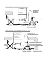
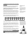
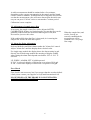
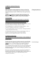
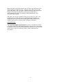
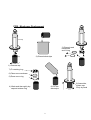
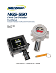
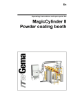
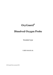
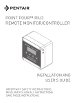
OxyGuard® PPB
ppb Analyser
for Dissolved Oxygen
User's Manual
Ser. Nr.:
Range:
Output:
Supply:
Div.:
Delivery
Checked by:
L01 PPB manual gb 0201
CONTENTS
1. DESCRIPTION
1.1 General ...........................................................................................................................1
2. INSTALLATION
2.1 General ...........................................................................................................................2
2.2 Transmitter Installation................................................................................................2
2.3 Measurement Chamber Installation ............................................................................3
2.4 Sample Water Connections...........................................................................................3
3. CALIBRATION AND ALARM SET POINT ADJUSTMENT
3.1 Calibration .....................................................................................................................5
3.2 Adjustment of Sample Water Flow..............................................................................6
3.3 Alarm Set Point Adjustment.........................................................................................6
4. SERVICE AND MAINTENANCE
4.1 General ...........................................................................................................................7
4.2 Fault Finding..................................................................................................................7
4.3 Membrane Replacement ...............................................................................................7
4.4 Spare Parts .....................................................................................................................8
5. SPECIFICATIONS and DETAILED DESCRIPTION
5.1 Transmitter ..................................................................................................................10
5.2 Probe .............................................................................................................................11
DIMENSIONAL DRAWINGS
1. DESCRIPTION
1.1 General
The OxyGuard ppb analyser is designed to measure dissolved
oxygen in feed water, condensate, district heating water or similar. The
standard model has a single range, but a dual-range model is also
available.
The OxyGuard ppb analyser consists of a transmitter unit and a
probe with measurement chamber.
The transmitter has a display that shows the measured value, a
galvanically isolated analogue output and an alarm output. It has a
calibration timer which blocks the alarm output and sets the analogue
output to its zero value, so that calibration can be performed without
triggering alarm.
The analyser can either measure a sample flow that is led to a drain or
measure on a by-pass loop at up to 6 bar pressure. When used with the
outlet to drain the measurement chamber is fitted with a check valve to
retain water in it at all times.
If there are two ranges,
range selection is made by
a " HI - LO" range selector
switch on the front panel.
Please read ALL this
manual before using the
instrument.
The probe is shipped in a transport chamber that contains water with
little or no oxygen, and the probe should not be removed until all parts
are installed and the probe is to be calibrated.
SPECIAL FEATURES
It is important to note that the OxyGuard PPB analyser has a number of
features that make its use and maintenance significantly different from
that of other analysers for low level dissolved oxygen.
If you are familiar with other analysers you must be aware that the
OxyGuard PPB analyser NEEDS MUCH LESS CARE AND
ATTENTION THAN OTHER SUCH ANALYSERS.
If the probe should ever need attention, i.e. if the membrane should
suffer damage, the necessary service can be performed by anyone on
the basis of the spares shipped with the unit and the instructions in this
manual. Special training is NOT needed.
It is important to note that
the probe functions best if
you do NOT take it apart
for maintenance!
THE OXYGUARD PPB ANALYSER IS A SENSITIVE
INSTRUMENT. PLEASE FOLLOW THE INSTRUCTIONS IN THIS
MANUAL CAREFULLY.
SPECIAL FEATURES
FAST RESPONSE
HIGH STABILITY
NO REGULAR SERVICE NEEDS
NOT SENSITIVE TO SAMPLE FLOW RATE
EASY TO CALIBRATE
FAST RETURN TO LOW PPB MEASUREMENT AFTER CALIBRATION
FAST AND EASY MEMBRANE REPLACEMENT
NO SPECIAL TRAINING NEEDED
NOT CROSS-SENSITIVE TO HYDROGEN
1
2. INSTALLATION
NB IMPORTANT: DO NOT REMOVE THE PROBE FROM
THE TRANSPORT CHAMBER UNTIL IMMEDIATELY
BEFORE INITIAL CALIBRATION. THE PROBE IS BEST
STORED IN LOW-OXYGEN WATER
THE FOLLOWING
INSTALLATION
PROCEDURE MUST
BE CARRIED OUT IN
THE STATED ORDER
THOROUGHLY FLUSH SAMPLE WATER PIPES BEFORE
CONNECTION TO THE MEASUREMENT CHAMBER
2.1 General
When planning installation please take any steps possible to ensure a
stable, accurate measurement. Both the surroundings and sample
should have a constant, moderate temperature. Do not subject the
equipment to vibration or radiant heat.
Oxygen diffuses through plastics, rubber etc. Use metal pipes with
welded, brazed or metal joints for the sample water. The flexible
aluminium tubing supplied with the equipment is ideal.
Even though the system is not sensitive to electrical noise it should, as
a matter of principle, NOT be placed near sources of electrical noise.
2.2 Transmitter Installation
NB.: MAKE SURE
THAT THERE IS
ENOUGH ROOM TO
THE SIDES OF THE
CABINET TO RELEASE
THE RIGHT-SIDE LOCK
WITH A LARGE
SCREWDRIVER AND
TO SWING THE TOP
HALF OPEN.
Mount the cabinet using the holes in the corners. Connect as indicated
below. Do not coil up, stretch or sharply bend the probe cable. Place
the probe cable so that the probe can easily be hung up for calibration.
Connect the probe - still in the transport chamber - and switch the
transmitter on. Please note that it can take 5 minutes for the equipment
to warm up and stabilize.
2.2.1 Electrical Connections
1
230 V
2
3
0 V earth
Mains Supply
4
5
6
7
8
NC
C
NO
+
-
Alarm relay
9
yellow
Analogue
Output
green
3
2
1
4
brown
grey
The pin numbers run clockwise, starting at the index notch, when
looking at the socket on the transmitter unit (from the outside).
2
11
12
13
brown NC yellow green grey
NB The probe connections are effected via a factory-wired connector.
The internal connections of the plug are as follows:
Probe connector
(transmitter socket)
and cable colours
10
To Probe
NB. It may in some cases
be practical to shorten the
cable. The procedure is
quite easy, but the proper
tools must be used
To keep the EMC
protection the probe cable
must be without joins and
terminated properly.
2.3 Measurement Chamber Installation
The chamber has 6 mm pipe fittings and is supplied mounted on a
plastic plate, with two holes for easy fixing - see the drawing at the
end of the manual. The inlet is normally to the left, the outlet to the
right, but the chamber can be supplied with the opposite flow
direction. The sample piping must be thoroughly flushed clean before
you connect it.
The measurement chamber is often fed with a sample flow that is led
to a drain afterwards. The check valve in the inlet means that you can
turn the flow off or even disconnect the inlet for long periods and still
retain low oxygen water from the last sample in the chamber so that
the probe does not need to be removed during operation standstills.
NB Use two spanners to
tighten fittings or you may
shatter the measurement
chamber.
NB. The probe is not crosssensitive to hydrogen.
The unit can also measure in a by-pass loop at up to 6 bar pressure,
eg. on stator cooling water. In this case the insert must be removed
from the check valve. Make sure that the piping system generates
sufficient pressure drop to ensure a flow of at least 100 ml/min
through the chamber.
2.4 Sample Water Connections
All sample water connections should be made in metal tubing such as
the aluminium tubing supplied, with connections either welded,
brazed or carefully made using metal compression ring fittings. The
sample should preferably be cooled to room temperature, since this
makes calibration even easier. The sample temperature should be kept
as constant as possible.
Flush all sample piping thoroughly and check that it can deliver at
least 100 ml/min at a suitable steady temperature. Connect the piping
to the measurement chamber and prepare for calibration.
WHEN THE ABOVE HAS BEEN PERFORMED YOU SHOULD
MAKE PREPARATIONS FOR CALIBRATION, THEN REMOVE
THE PROBE FROM THE TRANSPORT CHAMBER, CALIBRATE
IT AND PLACE IT IN THE MEASUREMENT CHAMBER AS
DESCRIBED IN THE FOLLOWING.
3
NB A flow of 100 ml/min
is sufficient. The
equipment will easily
measure at larger flow
rates, but larger flow rates
constitute a waste of water.
.
System configuration, atmospheric pressure measurement
AMPLIFIER
DO NOT KINK THE LEAD
LEAVE ENOUGH LEAD
TO LIFT PROBE
FOR CALIBRATION
AND CLEANING ETC.
W xD xH: 190 x 96 x 240 mm
4 mounting holes,
centres 161 x 220 mm
PROBE
SAMPLE
COOLER
DO NOT LET PIPING STRESS
THE MEASUREMENT CHAMBER
ALARM AND
ANALOGUE
OUTPUTS
TO MAINS
SUPPLY
CHECK VALVE
TO DRAIN
FLOW DIRECTION
NB. USE METAL PIPE AND FITTINGS
1
2
2
1
TIGHTEN WITH TWO SPANNERS
System configuration, measurement under pressure (max. 6 bar)
AMPLIFIER
1) DO NOT KINK THE LEAD.
LEAVE ENOUGH LEAD TO LIFT PROBE
FOR CALIBRATION AND CLEANING ETC.
W xD xH: 190 x 96 x 240 mm
4 mounting holes,
centres 161 x 220 mm
PROBE
SAMPLE
COOLER
ALARM AND
TO MAINS ANALOGUE
SUPPLY OUTPUTS
2) WHEN MEASURING UNDER PRESSURE ON
CLOSED SYSTEMS (EG. STATOR COOLING
WATER) REMOVE THE INSERT FROM THE CHECK
VALVE BODY AND ENSURE THAT THERE IS
ENOUGH PRESSURE DIFFERENCE TO MAINTAIN
FLOW THROUGH THE MEASUREMENT CHAMBER.
CHECK VALVE
NB. USE METAL PIPE AND FITTINGS
FLOW DIRECTION
1
2
2
1
TIGHTEN WITH TWO SPANNERS
4
3) DO NOT LET PIPING STRESS
THE MEASUREMENT CHAMBER
3. CALIBRATION AND ALARM SET POINT ADJUSTMENT
3.1 Calibration
Calibration once every
three months is often
sufficient.
Calibration is an easy process that can usually be performed in less
than two minutes. It is advisable to make all preparations before
removing the probe from the low-oxygen content water.
It is important to note that the longer the probe is in air during
calibration, the longer it will take for it to return to its working
point in very low oxygen content water.
The probe MUST have the same temperature as the air when it is
calibrated. If you adjust the sample water temperature to that of the
air, or place the probe in a beaker of low-oxygen-content water at air
temperature some minutes before taking the probe up for calibration
you will not have to wait a long time for temperature equalization.
The probe will not suffer
by being in the air for a day
or two, but it may take
some time before it again
measures accurately at a
few PPB.
Temperature equalization
has taken place when the
reading is steady.
For the greatest accuracy check the barometric pressure and find the
calibration value from the table. Otherwise calibrate to 100.
Prepare to remove the probe from the chamber. Clean its outside if
necessary. Note that the analogue output automatically goes to 4 mA
(the 0 ppb value) when the calibration timer is running.
Barometric
Pressure
Calibration
Value
mmHg
mBar
730
973
740
986
750
1000
760
1013
770
1026
780
1040
790
1053
96
97
99
100
101
103
104
You can now proceed as follows:
a) Press "Cal Init" to start the timer - see that the yellow lamp is lit.
b) Unscrew the ring and lift the probe from the chamber. If it was in
the transport chamber, or measured a liquid other than clean water,
rinse it thoroughly in clean water. Carefully dry the membrane with a
cloth or soft paper. Hang the probe in free air, away from sources of
direct heat.
The 7 minute calibration
timer blocks the alarm
function, sets the analogue
output to 4 mA (the 0 ppb
value) and changes the
amplification of the system
so that you always calibrate
to "100" or corresponding
corrected value.
c) Observe the display When the display reading is stable, which
usually takes about one minute, adjust the "CAL" front panel trimmer
until the display shows the calibration value.
d) Place the probe into the chamber - filled with water. NOTE THE
PLACING OF THE GASKET between the flange and chamber top.
e) Ensure that the seal seats correctly and that air bubbles are not
trapped in the chamber. Tighten the ring. If any bubbles are trapped
turn the flow off for a few seconds - the bubbles will rise to the
top of the chamber and be flushed out when the flow is turned on
again.
f) Check that the sample flow is approximately 100 ml/min.
5
NB.!
gasket
A stable measurement should be attained after a few minutes,
depending on the oxygen concentration in the sample and the length
of time it took to calibrate. If calibration took a long time and you can
see that the measurement value will cause alarm when the timer runs
out you can press "Cal Init" twice to start another 7 minute period.
Calibration is now complete.
3.2 Adjustment of sample water flow
If necessary the sample water flow can be adjusted AFTER
CALIBRATION: If there is a limited supply of water the flow can be
gradually reduced until the measured value begins to fall, then
increased to just over this value.
If the reading falls when the flow is increased, air is entering the
sample line. Locate the leak and repair it.
3.3 Alarm Set Point Adjustment
Push and hold the small black button under the "Alarm Set" control.
Adjust "Alarm Set" until the display shows desired value.
For single range models the display shows the alarm setting in ppb
directly, but in dual-range models the meaning of display reading
when setting the alarm limit depends on whether “HI” or “LO” is
selected:
I:E: WHEN “ALARM SET” is held depressed:
If “LO” is selected a display of 200 means a set point of 20.0 ppb
If “HI” is selected a display of 200 means a set point of 200 ppb.
Zero Check
Zero check is not necessary, but if you suspect that the zero has drifted
a little please contact your supplier or OxyGuard International A/S.
NB. NEVER PLACE THE PROBE IN CONCENTRATED
SODIUM SULPHITE SOLUTION
6
When the sample line (and
cooler, if used) are
correctly established the
measurement will be
constant over a very large
flow range.
4. SERVICE AND MAINTENANCE
4.1 General
There is no need for regular maintenance or service, just keep the
probe membrane free from deposits. The membrane can be wiped
clean with a cloth or soft paper. Do not try to scratch it clean with a
fingernail! Remember to press "Cal Init" before removing it from the
chamber.
All necessary spares etc.
are shipped with the unit.
THERE IS NO NEED TO CHANGE THE ELECTROLYTE
REGULARLY! The probe should not be taken apart unless the
membrane is damaged, e.g. due to accident when cleaning it.
4.2 Fault Finding
REMEMBER TO SWITCH OFF THE SUPPLY TO THE UNIT
AND TO CIRCUITS CONNECTED TO THE ALARM OUTPUT
BEFORE REMOVING THE FRONT PANEL OR TERMINAL
COVER - A HAZARD EXISTS IF THIS IS NOT DONE!
4.2.1 If the system is completely "dead" first change the fuse (160 mA
slow-blow). If this does not help, consult your dealer.
4.2.2 A sudden fault - e.g. with a zero or negative display - can be
caused by a damaged or faulty cable or connections.
4.2.3 An unstable display can also be caused by a damaged membrane
- check it and replace if necessary.
4.2.4 If the probe seems to be sensitive to small changes in flow, air
(oxygen) is entering the piping or measurement chamber.
Inspect/renovate the piping and chamber, check all joints.
4.3 Membrane Replacement
THIS SHOULD ONLY BE PERFORMED IF THE MEMBRANE
IS DAMAGED.
Switch off the unit.
Unplug and remove the probe. Carefully unscrew the cap and discard
the electrolyte. The anode should be clean. If there are deposits on the
cathode it can be carefully cleaned in water or under the tap using
grade 1000 emery paper. The cathode must NOT be polished.
A new membrane must be fitted to the cap. Unscrew the retaining ring
in the bottom of the cap using the special tool provided. Discard the
membrane and the O-ring. The cap and retaining ring should be rinsed
and dried thoroughly.
Place a new O-ring in the bottom of the cap and a new membrane on
top of the O-ring. Screw the retaining ring tightly into place. The
membrane must remain flat. If it wrinkles remove it and try again with
a new membrane and O-ring. It is important that all parts are
completely clean and dry.
7
See the drawings!
Rinse the probe in demineralised water. Fill the cap to the brim with
fresh electrolyte. Hold the probe vertically, move the cap up to the
probe and gently screw it in place without turning it back at any time.
Surplus electrolyte should trickle from the screw thread. It is
important that the probe is completely filled and that the cap is
screwed firmly in place.
The probe can now be regarded as new. It can, however, take a few
hours before it reaches its correct working point and stability. It
should therefore be calibrated, mounted back in the measurement
chamber and used for two days before being re-calibrated.
4.4 Spare Parts
The OxyGuard ppb oxygen analyser system is manufactured from
tried and tested parts of the highest quality, so the need for spare parts
is minimal. The parts delivered with the unit should cover the need for
spares for 20 years use, otherwise spares can be obtained from
OxyGuard.
8
PPB - Membrane Replacement
Probe Body
3) Discard used
membrane
and O-ring
Cap
2) Discard electrolyte
1) Unscrew cap
7) Fit retaining ring
6) Place new membrane
5) Place new o-ring
8) Fill with
electrolyte
4) Wash and thoroughly dry
cap and retainer ring
9
9) Assemble,
tighten cap
firmly by hand
5. SPECIFICATIONS and DETAILED DESCRIPTION
5.1 Transmitter
Construction:
Rilsan coated aluminium alloy enclosure with LCD display, calibration
and alarm set point adjustment, terminals, power supply, electronics and
alarm relay.
Dimensions:
b x d x h: 190 x 240 x 100 mm
Weight:
approx. 3 kg.
Supply:
230 VAC. Other on request.
Operating temperature: -5°C to 60°C
Encapsulation:
IP 65
Input:
Voltage signal from the probe. The input is galvanically isolated from the
output.
Analogue Output:
0-20 mA or 4-20 mA (as ordered). Max. loop impedance 700 ohm.
For 2 range model 20 mA = the full scale selected by range select switch.
E.G. 20 mA = 100 ppb if "LO" selected and 1000 ppb if "HI" selected.
Standard Range:
0-100 ppb. 2-range version “LO” = 100 ppb and “HI” = 1000 ppb.
Alarm output:
1 high alarm. Potential free change over switch, max. 200 VA relay
activates on rising or falling signal, as ordered.
System Accuracy:
+/- 1 ppb when measuring temperature = calibration temperature.
Saturation Curve:
DIN 38404, part 22 (1986).
The transmitter consists of a cast metal enclosure with front panel
assembly and a main circuit board. The front panel assembly
comprises the display, an alarm set control, calibration trimmer,
pushbuttons for alarm value display and calibration timer activation
and indicator for calibration timer. The main circuit board has
terminals, alarm relay, power supply and input and output circuits.
The input is the microvolt signal from the probe. The single range
model has as standard a measurement range of 0-100 microgram per
liter (ppb), the dual range 0-100 and 0-1000 microgram per litre
selected using a small ALO-HI@ switch. The display can over-range to
170 or 1700, but the analogue output is limited to 20 mA.
In the dual-range model the
analogue output changes to
correspond to the selected
range.
The analogue output in OxyGuard ppb analyser is galvanically
isolated from the input and can be factory set to either 0-20 mA or 420 mA, max load 700 ohms (4-20 mA is standard).
The alarm relay is usually coded to activate when the measured value
rises above the alarm value.
The alarm set point value is shown on the display when the small
black pushbutton under the "Alarm Set" control is held depressed.
The calibration timer, which runs for 7 minutes, is started and stopped
by pressing the "Cal Init" button. The yellow indicator lights when the
timer is running, during which time the alarm function is blocked, the
analogue output is set to the zero value and the amplification of the
system is changed to enable calibration.
10
Please note that the contact
output is a potential free
(dry) change over contact,
max. load 200 VA at 230
VAC.
5.2 Probe
Probe dimensions:
Type:
Sample temperature:
Temperature compensation:
Measurement Chamber:
Sample flow:
Sample pressure:
Response Time:
21.5 mm diameter x 135 mm with 3 m special cable.
Self polarizing (galvanic) membrane covered amperometric cell
5°C to 50(C
Automatic.
Clear acrylic chamber with 6 mm compression ring fittings and
valve.
Depends on oxygen content and temperature - min. 100 ml/min,
max. 2000 l/min.
up to max. 6 bar.
Less than 20 sec for 90% of a step change. From 1 minute in air
(calibration) to 100 ppb in approximately 40 sec, and to 10 ppb in
less than 3 minutes.
The probe is a galvanic measuring element which generates a
microvolt output proportional to the dissolved oxygen. It is
manufactured in stainless steel and consists of an upper part with
cathode, anode and cable, and a cap with membrane and electrolyte.
The cable between the probe and the transmitter unit is a special
screened 3 metre long cable with connector. The cable and connector
are EMC optimized to give the best possible noise protection. The
probe can be ordered with longer cable.
Oxygen diffuses through the membrane onto the cathode, where it
reacts chemically and then combines with the anode. This chemical
process develops an electrical current, which is converted into a
voltage (of approximately 50 μV at 10 ppb) via a linearization
resistor.
The measurement chamber has 6 mm compression ring fittings and
check valve in the inlet, all mounted on a plastic plate, ready for
fixing with two 6 mm screws - see the drawing at the end of this
manual. The check valve ensures that when measuring at atmospheric
pressure water from the last sample remains in the chamber - i.e. it
remains filled with water even if the feed is turned off.
IMPORTANT When the measurement is made on a bypass under
pressure (e.g. on stator cooling water) the check valve insert must be
removed.
The probe is not cross-sensitive to hydrogen.
N.B. The system has EMC (CE) approval
Standard Accessories
2 m flexible sample tubing
O-rings
User Manual
Membranes
Electrolyte
Special tool
The equipment is supplied ready for use
Data subject to change without notice
11
Transmitter Unit
96
90
150
190
Mounting hole centers 161 x 220 mm
35
40
40
40
approx. 150
All dimensions
in millimeter
27,5
7
55
2 holes,
6 mm dia.
76
90
approx.. 128
12
Measurement Chamber
with Probe