1
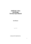
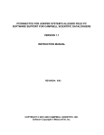
USER MANUAL CS512 Oxyguard Type III Dissolved Oxygen Sensor Issued: 27.7.15 Copyright © 2001-2015 Campbell Scientific, Inc. Printed under licence by Campbell Scientific Ltd. CSL 576 Guarantee This equipment is guaranteed against defects in materials and workmanship. This guarantee applies for 24 months from date of delivery. We will repair or replace products which prove to be defective during the guarantee period provided they are returned to us prepaid. The guarantee will not apply to: Equipment which has been modified or altered in any way without the written permission of Campbell Scientific Batteries Any product which has been subjected to misuse, neglect, acts of God or damage in transit. Campbell Scientific will return guaranteed equipment by surface carrier prepaid. Campbell Scientific will not reimburse the claimant for costs incurred in removing and/or reinstalling equipment. This guarantee and the Company’s obligation thereunder is in lieu of all other guarantees, expressed or implied, including those of suitability and fitness for a particular purpose. Campbell Scientific is not liable for consequential damage. Please inform us before returning equipment and obtain a Repair Reference Number whether the repair is under guarantee or not. Please state the faults as clearly as possible, and if the product is out of the guarantee period it should be accompanied by a purchase order. Quotations for repairs can be given on request. It is the policy of Campbell Scientific to protect the health of its employees and provide a safe working environment, in support of this policy a “Declaration of Hazardous Material and Decontamination” form will be issued for completion. When returning equipment, the Repair Reference Number must be clearly marked on the outside of the package. Complete the “Declaration of Hazardous Material and Decontamination” form and ensure a completed copy is returned with your goods. Please note your Repair may not be processed if you do not include a copy of this form and Campbell Scientific Ltd reserves the right to return goods at the customers’ expense. Note that goods sent air freight are subject to Customs clearance fees which Campbell Scientific will charge to customers. In many cases, these charges are greater than the cost of the repair. Campbell Scientific Ltd, 80 Hathern Road, Shepshed, Loughborough, LE12 9GX, UK Tel: +44 (0) 1509 601141 Fax: +44 (0) 1509 601091 Email: [email protected] www.campbellsci.co.uk PLEASE READ FIRST About this manual Please note that this manual was originally produced by Campbell Scientific Inc. primarily for the North American market. Some spellings, weights and measures may reflect this origin. Some useful conversion factors: Area: 1 in2 (square inch) = 645 mm2 Length: Mass: 1 in. (inch) = 25.4 mm 1 ft (foot) = 304.8 mm 1 yard = 0.914 m 1 mile = 1.609 km 1 lb (pound weight) = 0.454 kg Pressure: 1 psi (lb/in2) = 68.95 mb Volume: 1 UK pint = 568.3 ml 1 UK gallon = 4.546 litres 1 US gallon = 3.785 litres 1 oz. (ounce) = 28.35 g In addition, while most of the information in the manual is correct for all countries, certain information is specific to the North American market and so may not be applicable to European users. Differences include the U.S standard external power supply details where some information (for example the AC transformer input voltage) will not be applicable for British/European use. Please note, however, that when a power supply adapter is ordered it will be suitable for use in your country. Reference to some radio transmitters, digital cell phones and aerials may also not be applicable according to your locality. Some brackets, shields and enclosure options, including wiring, are not sold as standard items in the European market; in some cases alternatives are offered. Details of the alternatives will be covered in separate manuals. Part numbers prefixed with a “#” symbol are special order parts for use with non-EU variants or for special installations. Please quote the full part number with the # when ordering. Recycling information At the end of this product’s life it should not be put in commercial or domestic refuse but sent for recycling. Any batteries contained within the product or used during the products life should be removed from the product and also be sent to an appropriate recycling facility. Campbell Scientific Ltd can advise on the recycling of the equipment and in some cases arrange collection and the correct disposal of it, although charges may apply for some items or territories. For further advice or support, please contact Campbell Scientific Ltd, or your local agent. Campbell Scientific Ltd, 80 Hathern Road, Shepshed, Loughborough, LE12 9GX, UK Tel: +44 (0) 1509 601141 Fax: +44 (0) 1509 601091 Email: [email protected] www.campbellsci.co.uk Contents PDF viewers note: These page numbers refer to the printed version of this document. Use the Adobe Acrobat® bookmarks tab for links to specific sections. 1. General Information .................................................... 1 2. Specifications .............................................................. 2 3. Optional Sensor Accessories ..................................... 3 4. Optional Agitator ......................................................... 3 5. Application Information .............................................. 4 6. Wiring ........................................................................... 4 7. Programming ............................................................... 5 7.1. CRBasic ................................................................................................... 5 7.2. Edlog........................................................................................................ 8 8. Calibration .................................................................... 8 9. Maintenance ................................................................. 9 10. Agitator Control ......................................................... 9 Appendix A. Dissolved Oxygen Tables ..................................... A-1 Figures 1-1. CS512 ...................................................................................................... 1 4-1. Preventing Bio-fouling of the CS512 ...................................................... 3 4-2. CS512 with PT4 Agitator ........................................................................ 4 10-1. Agitator Wiring ................................................................................... 10 Tables 6-1. Sensor Wiring.......................................................................................... 4 7-1. Wiring for Example 1 .............................................................................. 5 7-2. Wiring for Example 2 .............................................................................. 7 i Examples 1. Sample CR1000 Program using VoltDiff ................................................... 5 2. Sample CR200 Program ............................................................................ 5 3. Portion of CR10X Sample Program using P1 ............................................ 8 4. Portion of CR10X Sample Program using P2 ............................................ 8 5. Sample Program using VoltSE ................................................................... 8 6. Sample Program using P36......................................................................... 9 7. Sample Program using Expression ............................................................. 9 8. Sample Program using P86 and P22 Instructions ..................................... 10 9. Sample Program using Portset .................................................................. 10 10. Sample Program using Portset ................................................................ 11 ii Campbell Scientific CS512 Oxyguard Type III Dissolved Oxygen Sensor An accurate and reliable sensor is a critical element in any measurement system. The Oxyguard Stationary Sensor meets these criteria for the measurement of dissolved oxygen. 1. General Information The Oxyguard Stationary Sensor is a galvanic sensor which produces a millivolt signal proportional to the amount of oxygen present in the measured medium. Oxygen diffuses through the membrane onto the cathode, reacts chemically, and combines with the anode. An electrical current is produced by this chemical reaction which is converted from microamps to millivolts by an in-line resistor. An in-line thermistor also conditions the signal providing automatic temperature compensation. With these features, the sensor produces a millivolt output proportional to the oxygen present in the medium in which it is placed. The sensor consists of two parts, an upper part with cathode, anode and cable, and a lower part comprising a screw on membrane cap with fitted membrane. The cap is filled with electrolyte and simply screwed onto the top component. The sensor is self-polarizing and requires no external power source. There are two wires to connect. Because the sensor's output is linear, it is possible to connect it directly to a data acquisition system capable of handling the small millivolt signal. The sensor's robust construction and simple design make maintenance and servicing it straightforward. There is no need to send the sensor back to the factory for servicing. It utilizes a strong, easy-to-clean and easy-to-change membrane in a screw-on membrane cap. Regular servicing is not required. When necessary the sensor can be fully overhauled in five minutes. Figure 1-1. CS512 1 Campbell Scientific CS512 Oxyguard Type III Dissolved Oxygen Sensor 2. Specifications Principle of Measurement: Membrane covered galvanic oxygen sensor Output Signal: 2.5 to 5 mV per mg 1-1 Repeatability: Better than 0.2 mg/l calibration temperature equals measuring temperature 5C Output Impedance: 1 kohm Response Time: After equilibration, 1 minute for 95% of final value Materials of Construction: Sensor body: O-rings: Membrane: 2 Delrin Membrane O-ring = Buna N Body Seal O-ring = Viton 0.05 mm (2 mil) Teflon Dimensions and Weight: 5.7 cm (2.28”) diameter x 5.8 cm (2.3”) height 450 g (15.9 oz.) Cable: standard length 7 m (23 ft); other lengths available upon request 2-wire 22 awg shielded, PVC jacketed Operating Conditions: Temperature Pressure: Minimum Submersion Depth: Minimum Water Flow: 0 to 40C (32 to 122F) 0 to 29 psig 60 mm (2 ½ in) 1 cm/s (.39 in/sec) across membrane Calibration: In air or in air saturated water Temperature Compensation: Automatic from 4 - 40C (40 - 104F) Range of Dissolved Oxygen: 0-20 mg/l, 0-200% Sat Ships with: 5 spare membranes with O-rings 50 ml electrolyte cathode cleaning pad User Manual 3. Optional Sensor Accessories 009994 — PT4 Agitator for stagnant conditions 010315 — DO electrolyte, 1 litre 010314 — Membrane kit, 10 membranes 4. Optional Agitator – available to special order only The PT4 Agitator is a reliable and robust agitator for use in conjunction with sensors subjected to bio-fouling in ponds and stagnant water conditions. O2 sensors require a minimum water velocity across their membranes to function properly. Therefore, to measure DO in stagnant water conditions, it is necessary to move the water past the membrane to get accurate and reliable DO measurements. In many instances the water also has a high bio-loading and the sensors become fouled resulting in inaccurate DO measurements. Figure 4-1. Preventing Bio-fouling of the CS512 The PT4 Agitator overcomes these problems. The device is designed so that a soft bristle brush sweeps across the sensor membrane or sensor tip. This sweeping action of the brush provides the required water velocity as well as prevents the membrane from becoming bio-fouled. The optimum sweeping frequency depends upon the design of sensor and type of membrane used and water conditions. An ON-time of 0.25 seconds and OFF-time of 5 seconds is suitable in most circumstances. Agitator’s overall size: 180 mm x 83 mm, diameter, 0.6 kg (7-1/8" x 3-1/4", 1-1/4 lb). Supplied with 3 metres (10 ft.) cable. Power required: 10.5 to 18 VDC at the agitator, 1.1 amps. Maximum ON-time is 3 seconds. 3 Campbell Scientific CS512 Oxyguard Type III Dissolved Oxygen Sensor Figure 4-2. CS512 with PT4 Agitator Optional Repeat Cycle Timer for Agitators: Reciprocating action may be controlled by the optional solid state Repeat Cycle Timer. It sends 12 VDC pulses to the agitator coil. The ON-time is 0.25 sec. The OFF-time is adjustable from 3 to 12 sec.; requires supply voltage 10 to 17 VDC; housed in watertight cylinder 170 mm x 50 mm diameter (6.6" x 2"). 5. Application Information NOTE SCWin users: This manual was written primarily for those whose needs are not met by SCWin. Your procedure is much simpler: just add the CS512 sensor (it’s in the water folder), save your program, and follow the wiring shown in Step 2 of SCWIN. 6. Wiring The CS512 sensor can use one differential channel or one single-ended channel. Differential wiring is better at rejecting electrical noise and ground loop error. Table 6-1. Sensor Wiring 4 CR510, CR10X, CR800, CR850, CR23X, CR1000, CR3000 CR200 Series Signal + Differential High, or Single-Ended Channel Single-Ended Channel Signal - Differential Low or AG Ground Colour Function Brown Blue User Manual 7. Programming 7.1 CRBasic In the CR800, CR850, CR1000, CR3000, and CR5000, the VoltDiff or VoltSE can be used to measure the CS511. In the CR200-series dataloggers, only the VoltSE instruction can be used since these dataloggers do not support differential measurements. Example program 1 is a CR1000 program that uses the VoltDiff instruction. Example Program 2 is a CR200 program. EXAMPLE 1. Sample CR1000 Program using VoltDiff This example is a CR1000 program but programming for the CR800, CR850, CR3000, and CR5000 is similar. Table 7-1 shows the wiring for the example. Table 7-1. Wiring for Example 1 CR1000 Connection Sensor Wire 1H Brown 1L Blue Ground Clear 5 Campbell Scientific CS512 Oxyguard Type III Dissolved Oxygen Sensor 'CR1000 'Created by Short Cut (2.5 Beta) 'Declare Variables and Units Public Batt_Volt Public DOmV Public DOppm Units Batt_Volt=Volts Units DOmV=mV Units DOppm=ppm 'Define Data Tables DataTable(Table1,True,-1) DataInterval(0,60,Min,10) Sample(1,DOmV,FP2) Sample(1,DOppm,FP2) Sample(1,Batt_Volt,FP2) EndTable DataTable(Table2,True,-1) DataInterval(0,1440,Min,10) Minimum(1,Batt_Volt,FP2,False,False) EndTable 'Main Program BeginProg Scan(5,Sec,1,0) 'Default Datalogger Battery Voltage measurement Batt_Volt: Battery(Batt_Volt) 'CS512 Dissolved Oxygen Probe measurements DOmV and DOppm: VoltDiff(DOmV,1,mV250,1,True,0,_60Hz,1,0) DOppm=DOmV*0.34 'Note use exact calibration factor (see section 8) 'Call Data Tables and Store Data CallTable(Table1) CallTable(Table2) NextScan EndProg EXAMPLE 2. Sample CR200 Program The CR200-series must use the VoltSE instruction since these dataloggers do not make differential measurements. If the other CRBasic dataloggers use the VoltSE instruction instead of the VoltDiff instruction, their programming will be similar to this example. Table 7-2 shows the wiring for the example. 6 User Manual Table 7-2. Wiring for Example 2 CR200 Connection Sensor Wire SE1 Brown Ground Blue Ground Clear 'CR200 Series 'Created by Short Cut (2.5 Beta) 'Declare Variables and Units Public Batt_Volt Public DOmV Public DOppm Units Batt_Volt=Volts Units DOmV=mV Units DOppm=ppm 'Define Data Tables DataTable(Table1,True,-1) DataInterval(0,60,Min) Sample(1,DOmV) EndTable DataTable(Table2,True,-1) DataInterval(0,1440,Min) Minimum(1,Batt_Volt,False,False) EndTable 'Main Program BeginProg Scan(10,Sec) 'Default Datalogger Battery Voltage measurement Batt_Volt: Battery(Batt_Volt) 'CS512 Dissolved Oxygen Probe measurements DOmV and DOppm: VoltSE(DOmV,1,1,1,0) DOppm=DOmV*0.34 'Note use exact calibration factor (see section 8) 'Call Data Tables and Store Data CallTable(Table1) CallTable(Table2) NextScan EndProg 7 Campbell Scientific CS512 Oxyguard Type III Dissolved Oxygen Sensor 7.2 Edlog Edlog Instruction 1 or 2 can be used. Example 1 shows the single-ended instruction for measuring the Sensorex probe; example 2 shows the differential instruction. The example measurement instructions that follow do not store data to final storage. Additional instructions (typically P92, P77, and output processing instructions such as P70) are required to store data permanently. EXAMPLE 3. Portion of CR10X Sample Program using P1 1: Volt (SE) (P1) 1: 1 2: 24 3: 1 4: 1 5: 1.0 6: 0.0 Reps 250 mV 60 Hz Rejection Range ; code 23 used for CR23X SE Channel Loc [ DOmV ] Multiplier *See Calibration* Offset EXAMPLE 4. Portion of CR10X Sample Program using P2 1: Volt (Diff) (P2) 1: 1 2: 24 3: 1 4: 1 5: 1.0 6: 0.0 Reps 250 mV 60 Hz Rejection Range ; code 23 used for CR23X DIFF Channel Loc [ DOmV ] Multiplier *See Calibration* Offset 8. Calibration The multiplier is used to calibrate the CS512 sensor. To calculate the multiplier: 1) Program the datalogger using a multiplier of one. 2) Place the OxyGuard sensor in the air, shaded from the sun. Wait for readings to stabilize. This may take 15 minutes or more. 3) Determine the air temperature and barometric pressure. 4) Using a calibration chart such as that provided in the sensor’s manual, determine the oxygen concentration of the air. 5) Use the following equation to calculate the multiplier: M = P/R M = Multiplier P = Concentration in PPM of the air (from the calibration chart in Appendix A) R = The signal output of the OxyGuard sensor when using a multiplier of one 6) Change the multiplier in the datalogger program from one to the calculated number. A more common way to enter the multiplier is to insert a separate instruction in the program. This will allow a new multiplier to be added to the program without rewriting, compiling, and downloading the program to the data logger. 8 User Manual In the CR510, CR10X, and CR23X, use Instruction P36. The multiplier is entered into an input location called DOmult using the numeric display in PC200W, PC208W, LoggerNet, PC400, PConnect, PConnectCE, or the CR10KD. EXAMPLE 6. Sample Program using P36 57: Z=X*Y (P36) 1: 1 X Loc [ DOmV 2: 2 Y Loc [ DOmult 3: 3 Z Loc [ DOppm ] ] ] In all dataloggers that use CRBasic, an expression is written. The multiplier value is entered into the expression through the Public Table using the numeric display in PC200W, LoggerNet, PC400, PConnect, and PConnectCE. EXAMPLE 7. Sample Program using Expression DOppm = DOMult * DOmV 9. Maintenance The CS512 sensor needs little maintenance. Regular cleaning of the membrane is all that is required. The membrane is very durable and can be cleaned with a cloth or soft paper. Do not scratch it clean with your fingernail. 10. Agitator Control In low flow conditions (less than about 5 cm/sec), it may be necessary to add an agitator to the CS512 sensor. Campbell Scientific ships the agitator with a repeat cycle timer. Using the repeat cycle timer requires no datalogger programming. However, some users choose to use a solid state relay and have the datalogger agitate the water on the sensor face either periodically throughout the day or just before measurement. Agitating just before the measurement saves on power and causes less wear and tear on the agitator and sensor membrane. The wiring for the agitator as controlled by this example program would be as follows: Ground/G 4 Agitator Datalogger Port C1 BLACK 1 #7321 Relay Crydom D1D07 3 WHITE 2 + 12 V Battery Figure 10-1. Agitator Wiring 9 Campbell Scientific CS512 Oxyguard Type III Dissolved Oxygen Sensor The following instructions would trigger the agitator as discussed in the agitator manual. In the CR510, CR10X, and CR23X, use instruction P86 and P22. EXAMPLE 8. Sample Program using P86 and P22 Instructions 45: Do (P86) 1: 41 Set Port 1 High 46: Excitation with Delay (P22) 1: 1 Ex Channel 2: 20 Delay W/Ex (units = 0.01 sec) 3: 0 Delay After Ex (units = 0.01 sec) 4: 0 mV Excitation 47: Do (P86) 1: 51 Set Port 1 Low 48: End (P95) In the CR200 series dataloggers, use the Portset instruction. EXAMPLE 9. Sample Program using Portset Portset (1,1) Delay(500,msec) Portset(1,0) In the CR1000, CR800, CR850, and CR3000 dataloggers, use the Portset instruction. EXAMPLE 10. Sample Program using Portset Portset (1,1) Delay (1,500,msec) Portset (1,0) The above example is not as power efficient as possible and would require AC power to maintain a sufficient battery charge. If it is necessary to operate an agitator without AC power available, write the program so that the agitator is only operated for a short period of time just before the measurement is to be taken. 10 Appendix A. Dissolved Oxygen Tables A-1 Appendix A. Dissolved Oxygen Tables A-2 CAMPBELL SCIENTIFIC COMPANIES Campbell Scientific, Inc. (CSI) 815 West 1800 North Logan, Utah 84321 UNITED STATES www.campbellsci.com [email protected] Campbell Scientific Africa Pty. Ltd. (CSAf) PO Box 2450 Somerset West 7129 SOUTH AFRICA www.csafrica.co.za [email protected] Campbell Scientific Australia Pty. Ltd. (CSA) PO Box 8108 Garbutt Post Shop QLD 4814 AUSTRALIA www.campbellsci.com.au [email protected] Campbell Scientific do Brazil Ltda. (CSB) Rua Apinagés, nbr. 2018 - Perdizes CEP: 01258-00 São Paulo SP BRAZIL www.campbellsci.com.br [email protected] Campbell Scientific Canada Corp. (CSC) 14532 – 131 Avenue NW Edmonton, Alberta T5L 4X4 CANADA www.campbellsci.ca [email protected] Campbell Scientific Centro Caribe S.A. (CSCC) 300N Cementerio, Edificio Breller Santo Domingo, Heredia 40305 COSTA RICA www.campbellsci.cc [email protected] Campbell Scientific Ltd. (CSL) 80 Hathern Road, Shepshed, Loughborough LE12 9GX UNITED KINGDOM www.campbellsci.co.uk [email protected] Campbell Scientific Ltd. (France) 3 Avenue de la Division Leclerc 92160 ANTONY FRANCE www.campbellsci.fr [email protected] Campbell Scientific Spain, S. L. Avda. Pompeu Fabra 7-9 Local 1 - 08024 BARCELONA SPAIN www.campbellsci.es [email protected] Campbell Scientific Ltd. (Germany) Fahrenheitstrasse13, D-28359 Bremen GERMANY www.campbellsci.de [email protected] Campbell Scientific (Beijing) Co., Ltd. 8B16, Floor 8 Tower B, Hanwei Plaza 7 Guanghua Road, Chaoyang, Beijing 100004 P.R. CHINA www.campbellsci.com [email protected] Please visit www.campbellsci.com to obtain contact information for your local US or International representative.