1
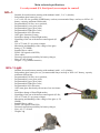
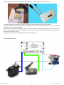
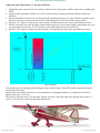
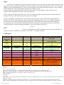
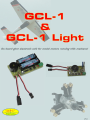
Excluding liability:
Jelen this leaflet contains only information relating to the product! The eletronic control unit cannot be used in vehicles, medical equipment and in
any kind of equipment, which may become dangerous to human body in increased extent in case of failure! The controller unit is not a toy, its
installation, use needs special skill! The manufacturer does not take up any liability for the damage caused by unprofessional installation or usage!
Caution:
Please read this user manual carefully before installation and taking into operation the equipment.
Safeguard the manual for later usage.
The appearance and specification of the device can be modified by the manufacturer without any prior notification.
The specified limits of electric parameters must not be exceeded in any conditions.
Should any repair become necessary, enlist the help of a skilled technician.
Do not expose the device to radiating heat and moisture.
Do not disassemble or modify the device.
Attach peripherial devices only in the prescribed and allowed way.
Take care of the cabling and wiring, which must be arranged in a way so that it could be easily to be reviewed .
Do not overload or short circuit the outputs.
Waste disposal:
The wate-disposal mark attached to the product symbolises that the product is under the effect of the 2002/96/EC EU-directive.
Any electric product must be collected separately from the communal/municipal waste using the devices provided by the government or by the
local authorities.
Proper disposal of your old or unusable tools and materials may help to prevent possible damages harmful to the health or the environment.
In case more information is needed regarding the disposal of old or unisable tools and materials please consult the environmerntal rules
applying to the problem.
M & V Elektronika
Kereskedelmi és Szolgáltató Kft.
Gyula u. 54, Miskolc, Hungary.
Web: www.hobbycnc.hu, www.rc-miskolc.emiter.hu, www.cnc-elektronika.hu, www.quantumservo.com
e-mail: [email protected]
© 2010. All rights reserved.
Introduction:
Thank you for choosing our product.
The on-board glow eletronic unit GCL-1 and GCL-1 Light is a motor stabilising and aviation
safety device, that provides complicated services and all of its parameters can be programmed.
The unit can be used in model planes, cars and ships. The electronic unit, which warms up with its
own battery the glow-plugs of motors running with methanol depending on the position of the
accelerator arm, must be placed inside of the model.
With its use the idle running of motors using with methanol will be smooth and the operation
safety will improve in a great extent. The motor-standstills caused by sudden cooling of the plug
and the forced landing will be eliminated. By its use the nitro-methane content of the fuel can be
reduced, saving money by that during the operation. There is no need for external glow at start and in case of falling out of the radio
reception the motor will be automatically stopped (Fail Save mode).
In the course of designing of GCL the most important needs of the people using the models have been taken into account and the
electronic unit has been developed according to these needs. After connecting it there is no need for either any handling buttons,
switches or LED displays. All of its functions (starting the motor, changing the flight mode, stopping the motor, switching off the
glow) can be activated with the accelerator arm of the remote controller. The complicated signals are presented by the means of a builin, high-power (85 dB) piezo loudspeaker, so it can be heard very well from longer distance, even though the loudspeaker is placed
inside the plane.
The electronic unit can be programmed with the help of three push-buttons and a LED. The setup, whose data are preserved even
when the power supply is off, has to be done only once.
The lower and upper glow level can be freely programmed. The extent of the gflow of the flight mode can be adjusted in 5 grades (so
that the life of the battery and plug could be saved).
In case of fall-out of the radio reception the control electronic unit activates its own Fail Save function, whose servo position can also
be freely programmed. In Fail Save mode it shuts off the nebuliser and switches off the glow, then it sends alarm signals with the help
of piezo.
At moptor-start the controller provides full (100%) glow, whose activation needs carry out a special moving protocol of the
accelerator arm. After take-off the starting protocoll (controlled by the position of the accelerator arm) automatically changes to flight
mode (reduced glow among the programmed ranges). Each change in its own state is signalled by unambiguous signals. In case of
switch-off the radio, the glow is automatically switched off. The controller is able to interpret and carry out the Motor Cut (Stop)
command of the transmitter too.
GCL continually monitores the state of the glow battery and if its voltage level decreases below of the critical value, it will signal that
with a sound signal and stops further glow. Doing so it prevents the deep discharge of the battery and increases its life-time. As a glow
battery a 1 or 2 cells NiMH AA size battery can be used (1.2V/cell). Its capacity should be at least 2400mAh.
Both circuits have an extra filtering in the servo part, which provides smoother power supply for th other on-board devices.
The circuits run either with 5V or with 6V (in servo side) system voltage.
GCL-1 is a full built-up device, which contains the socket for the 2-cell AA size battery, the servo cables and all the cables necessary
for motor glowl as well.
GCL1 Light is a lighter, smaller version, which does not contain the socket for the batteries and the glow-cable. This is recommended
for smaller machines.
GCL = Glow Control Logic
Main technical specifications:
Use only normal (FS, Fast Speed) servo output for control!
GCL-1:
-
Suitable for model motors running with methanol with 1, 2 or 3 cylinders,
Independent glow battery for use,
1 or 2-cell, AA size (parallel) NiMH battery sockets (recommended Sanyo eneloop or NiZn 1.6V
battery, capacity minimum 2000 mAh),
Programmable Fail Save servo position,
Programmable Lower glow point,
Programmable Upper glow point,
Programmable Flight glow value,
Programmable Servo direction,
100% glow function for start,
Switchless change of Start/Flight modes,
Signalling of the sate with intense sound signals (85
dB),
Use of 5V and 6V as system voltages,
Monitoring and handling of the voltage of the glow
battery (1.2V NiMH),
Installed Servo cables,
PWM / ON signals with LEDs,
Glow cables,
External connection possibility for battery charger,
Sizes: 87×45×24 mm
Weight: 33.5g (without batteries)
GCL-1 Light:
-
Suitable for model motors running with methanol with 1, or 2 cylinders,
Independent glow battery for use, (recommended Sanyo eneloop or NiZn 1.6V battery, capacity
minimum 2000 mAh),
Programmable Fail Save servo position,
Programmable Lower glow point,
Programmable Upper glow point,
Programmable Flight glow value,
Programmable Servo direction,
100% start-glow function by the means of an accelerator
arm,
Switchless change of Start/Flight modes,
Signalling of the sate with intense sound signals (85 db),
Use of 5V and 6V as system voltages,
Monitoring and handling of the voltage of the glow (1.2V
NiMH),
Installed Servo cables,
PWM / ON signals with LEDs,
External connection possibility for battery charger,
Sizes: 62×37×24 mm
Weight: 24g
Installation:
The installation of GCL1 and GCL-1 Light is nearly the same, the differences
will be mentioned and emphasized. In the descriptions plain models are
supposed to be equipped with a motor-contol electronic unit, but the description
can be applied to any kind of models. The elctronic unit must be connected
between the receiver and the servo unit of the motor accelerator.
The mounting operations must be carried out when the power supply is off and
the batteries are removed from the unit.
When choosing the place for the unit, the accessibility of the programming
buttons and shift of the center of gravity caused by the mass of the batteries
must also be taken into account. The setup and adjustment must be carried out
only once, after that the electronic unit does not any special care, but the accessibility of the batteries for
change must be taken into account.
For fixing use the attached green 5 mm thick hard sponge. The template/gauge, which can be found at the end
of the description, must be printed in a ratio of 1:1, and the proper template and sponge must be cut out.
After cutting out the areas marked with „X”, the holes arisen by that should be copied/marked into/on the
sponge.
Put the sponge onto the controller unit and press a little-bit, so that its internal side could take up the form of
the parts.
GCL-1 & GCL-1 Light
4
www.rc-miskolc.emiter.hu
Apply a thin layer of glue used with thermal pistoles to its four corners and crush them up.
Using this surface, the unit can be fixed by some glue to the internal side-wall of the model.
So that accidental short-circuits could be avoided, take care that the circuit cannot come into contact with any
metallic surface (eg. metal pushers).
The unit does not produce any high frequency noise, therefore it can be placed right next to the receiver too.
GCL-1 has sockets for its own glow batteries, in case of the Light version the problem of fixing the batteries
must be solved by the owner.
The glow cables must be led through the „firewall” of the motor.
Connection of GCL-1:
GCL-1 & GCL-1 Light
5
www.rc-miskolc.emiter.hu
Connection of GCL-1 Light:
The accelerator-control servo has to be connected to the Servo connector, the receiver has to be connected to
the Rec. connector. Use FS output/mode for servo output! Take care of the right polarity of the cables. The
glow cables must be connected to the Glow terminal screws (attached to GCL-1), the 4-mm ground cable with
a clip has to be connected to the left-side terminal screw, while the glow cable has to be connected to the
right-side terminal screw. Take care of the good metallic connection between the ground cable and the motor
body (in case of a painted motor, the paint must be removed from the surface under the fixing screw at the
clip)! In case of the Light version the glow cables and the sockets for the batteries must be provided by
the owner, or the technician performing the installation. The metallic part of the glow connector must not
come in contact with any metallic parts of the motor (eg. heatsink of the cylinder head), except for the middle
toe of the plug.
(plug connector)
GCL-1 & GCL-1 Light
6
www.rc-miskolc.emiter.hu
In case of a motor with more than 1 cylinder, the positive (right-side) filament of the glow cable must be
distributed among the plugs.
Attention!
GCL-1 : is able to control motors with 1 – 2 – 3 cylinders,
GCL-1 Light: is able to control motors with only 1 – 2 cylinders.
The metal body of the motors cannot be in metallic connection with any other electric devices.
The Fail Save function works only with receivers, which do not tug the servos after fall-out of the
reception. The use of receivers running at 2.4GHz, or receivers of Dual Conversion type is
recommended.
If there are more cylinders than the unit is cabable to handle, the number of the controlling units must be
increased and the control must be carried with the use of a „Y”-type servo cable.
In case of the Light version wires with a minimum cross-section of 1 mm2 (for both of the glow and those of
the wires of the batteries) must be used for cabling. Because of the high current it is important to keep the
transitional electric resistance as low as possible. If it is necessary, the batteries must be parallel-connected,
(positive pole must be connected to positive pole of the other battery, negavie pole must be connected to
negative pole of the other battery). It is necessary only if the capacity of 1 battery isn't sufficient (especially
recommended for motors with 2 or 3 cylinders).
NiMH AA-size batteries with a capacity of minimum 2400 mAh must be used.
In case of GCL-1 it is possible to build-in connectors for an external charger too. For this purpose 2 soldered
pins can be found on the PCB (at the lower and the upper end of the place for the batteries) with marking (5
(+) and 6 (-).
After installation the controller must be set-up.
GCL-1 & GCL-1 Light
7
www.rc-miskolc.emiter.hu
Permanent adjustments (Setup):
Both types must be used in the same way.
Before performing any set-up, irrespectively of the controller the motor has to be adjusted in the traditional
way (programming the transmitter, ajustment the direction and end position of the servo, tuning of idle
running and motor Stop function). This can also be performed using GCL. GCLs are delivered with a factory
set-up, but these can be regarded only as initial values (they have to be tuned with Your machine for the
correct operation).
In the course of setting-up GCL the board power supply (servo-circuit) and the transmitter must be switched
on and off several times. It is recommended to build-in an external switch for the power supply (this is
important for other reason too).
During set-up the 3 buttons and a LED found on GCL controller will be used.
The „FS” („Fail Save”) button is to record the servo position to be reached in case of fall-out of reception (or
switching off the transmitter) as well as it has a task during Setup.
The „Lo” button is to record the servo position of the lower glow limit and to input Setup functions too.
The „Hi” button is to record the servo position of the upper glow limit and to input Setup functions too.
The LED shows the extent of the glow with unplugged glow connection (with variable light intensity, this is
the PWM signal). When the glow cable and the batteries are connected, it shows the on and off states
(ON/OFF).
In the course of taking the unit into operation the flollowing important steps have to be performed:
1.
2.
3.
4.
Switch off the transmitter and the receiver (the on-board power supply).
Unplug the glow cable and remove the batteries.
Put the accelerator arm on the transmitter into idle running position.
Switch on the transmitter and the receiver then wait until the connection builds up (in case of 2.4 GHz).
When the connection has built up the GCL will sign it with 3 short beeps.
5. Press both the „Hi” and „Lo” buttons at the same time and hold the buttons pressed until the GCL
continually beeps.
6. Release the buttons (some longer beeps can also be heard following that).
7. Switch off the receiver (the on-board power supply).
By doing so, the servo direction reference (normal/inverse) has been given to the controller. If you fail to carry out that adjustment, the Lo and Hi
buttons might as well operate in a reverse way, which may cause problems later.
Adjustment of the Fail Save position:
1. Unplug the glow cable (it is necessary so that the state of glow could be observed by watching the LED).
2. Switch on the transmitter and the receiver (the on-board power supply).
3. Put the transmitter into Engine Cut/Stop position. In this case the servo must totally block the nebuliser.
At this point press once the „Fail Save” („FS”) button. The GCL will sign with 5 short bips that it has
stored the position.
4. Put the transmitter into the Idle Running position and you can switch off everything.
Adjust the glow value for the flight mode:
1. Unplug the glow connector (it is necessary so that the state of the glow could be observed by watching the
LED.
2. Switch on the transmitter.
3. Press the „Fail Save” („FS”) button, then switch on the receiver (the on-board power supply).
4. Hold the button pressed until the connection builds up (2.4 GHz), GCL will signal when it is ready with 4
long beeps. Then GCL will enter PWM Setup mode.
5. The actual glow level can be monitored by watching the intensity of the LED. The glow level can be
increased by pressing the „Hi” button, and can be decreased by pressing the „Lo” button. A step will cause
20 % change of the glow level either upward or downward (0-25-50-75-100%). It is recommended to
choose 50% - 75% values at first. In the course of idle running tests it can be fine-tuned at any time.
6. Swith off both the transmitter and the receiver.
GCL-1 & GCL-1 Light
8
www.rc-miskolc.emiter.hu
Fine tuning (practical adjustments)
Adjust the glow limit values (i. e. the glow window):
1. Unplug the glow connector (it is necessary so that the state of the glow could be observed by watching the
LED).
2. Switch on the transmitter and the receiver (the on-board power supply) and wait until the connection
builds up.
3. Put the transmitter into the lowest (trimmered) idle running position (it is not the Fail Save position, above
that there must be a point at hich the motor is still running, that is the lowest idle running point).
4. Press the „Lo” button (2 short beeps can be heard). It means that the lower glow point has been stored.
5. Put the accelerator arm into the upper position whose glow level you want to apply as the highest one (it is
recommended to choose the 1/3-1/4 position of the full length of the accelerator level).
6. Press the „Hi” button (2 long beeps can be heard). It means that the upper glow point has been stored.
(glow window)
Test and practice the starting protocol and glow states with the help of the LED (further information can be
found in the following).
Mount back and connect all parts have been unmounted or unplugged and then everything has been been
adjusted, the unit is fit for use.
The properly choosen glow level and glow window provides a safe and stable idle running of the motor as
well as it saves the life of the starting plug and batteries.
GCL-1 & GCL-1 Light
9
www.rc-miskolc.emiter.hu
Usage
Motor-start:
With precharged batteries and connected wires.
GCL will begin an automatic motor-start programme every time when the receiver
is switched on and the connection has built up, or following the arrival of the
transmitter signal after Fail Save, if the following acceleration motion steps have
been performed:
1. Let the position of acceleration arm in the glow window (eg. in idle runing) at the time of build-up the
radio connection.
2. Put the acceleration level up to the most upper position.
3. Use the choke (if it is necessary).
4. Put back the arm into the glow window. Then the unit signals the switching-on of the start (100%) glow
with 1 long beep.
5. Now the motor can be started.
6. When the motor is running, push the arm into the most upper position. Then the unit signals the change
into flight mode with 2 short beeps (it is not sure whether you can hear them because of the motor noise).
7. Now we can fly!!!
If the unit must be restarted for any reason (eg. the motor has stopped, or or we ourselves stopped it using
Motor Cut/Stop), then either the receiver (the on-board power supply) or the transmitter (Fail Save) must be
switched off and on and the steps of points 2 – 7 must be repeated.
If in glow mode the Motor Cut/(Stop) is pressed once (and then the glow level goes under the lower glow
limit), then 2 short beeps will signal the final switching off of the glow.
(Startingng and flight programme)
The particular glow states can be tested and practiced with the help of the LED
(with unplugged connector).
GCL-1 & GCL-1 Light
1
www.rc-miskolc.emiter.hu
Flight:
In the course of flight, if the position of the accelerator level is in the glow window (between the lower and
upper limit values), then the glow will be carried out using the value adjusted during set-up (50% - 75% of the full
length are the recommended values). If the accelerator arm goes above the upper limit, the glow will be switched
off (so that the life of the plug and that of the batteries could be saved).
If the accelerator level goes under the lower limit, then the glow will be finally switched off (this is the
position of the standstill of the motor, see the figure above).
If the voltage of the battery falls below 0.9V, GCL will sign with long beeps this situation and will switch off
the glow. In this case the batteries must be replaced or recharged.
In case of falling out of the reception, GCL goes into Fail Save mode. In this mode it emits long beeps and
puts the servo of the acceleration arm into the position stored during Setup, as well as it switches off the glow
(so that the motor could be stopped as quickly as possible). If the radio connection has been built up again,
then it puts the servo into the position determined by the acceleration arm (normal movement). At this time it
is possible again to restart the starting programme (see the description of the start).
Signals
LED:
In case of unplugged glow cable it shows the extent of the glow (PWM), all
other cases it shows whether the controller is on or off, i. e. controller ON/OFF.
Sound signals:
Mode:
Number of beeps:
Type of beeps:
Meaning
After switching on
3
Short
Radio connection is OK
At starting the
motor
1
Long
Starting mode is ON
Remark:
After Fail Save too, if the connection is
built up again.
100% glow is ON.
Return to flight mode
or
Switching off the glow (in case of Motor
Cut)
Its voltage is lower than 0.9V.
The radio connection is broken.
The motor is stopped, glow is switched
off.
By pressing the „Fail Save” („FS”)
button
At starting the
motor
2
Short
Starting mode is OFF
During flight
Uniform periode
Battery is flat
During flight
Periodic
long
2 long
+
1 long break
During Setup
5
Short
During Setup
2
Short
During Setup
2
Long
Setup
Continual
(al long as the button is
pressed)
Continual
Direction reference of
Servo is stored
By pressing the „Lo” + „Hi” buttons (with
radio reception ON)
Long
Adjustment of the flight
glow
„FS” button + switching on
+ radio reception„ stepwise changing by
the Lo” and „Hi” buttons,
theextent of PWM level can be
monitored by observing the LED.
Setup
4
Fail Save is activated
Fail Save position is
stored
Lower glow position is
stored
Upper glow position is
stored
By pressing the„Lo” button
By pressing the „Hi” button
Legend:
GCL = Glow Control Logic.
Fail Save = Saving in emergency. The measurements to be done in case of falling out of the radio reception.
PWM = Pulse-width modulation. A method of the analogue heating regulation by pulses with variable duty cycles.
NiMH = Nikkel- metal-hibrid AA-size batteries. Their cell voltage is 1.2V
Glow = Glow plug.
Hi = High.
Lo = Low
Glow window = The area between the lower and upper servo position determined by the „Lo” and „Hi” buttons. In this area is the area of the
flight glow (PWM).
Motor Cut = Motor-stopping possibility on the transmitter. If it is activated, the nebuliser will be totally blocked and the motor stops.
mAh = The energy-storing capacity of the batteries. They can produce as much current as the numbers indicate (in mA units) for an hour.
GCL-1 & GCL-1 Light
1
www.rc-miskolc.emiter.hu
GCL-1 és GCL-1 Light:
www.rc-miskolc.emiter.hu
www.hobbycnc.hu
www.cnc-elektronika.hu
www.quantumservo.com
GCL-1 & GCL-1 Light
1
www.rc-miskolc.emiter.hu
Felfogatási szivacssablonok
GCL-1 sablon
GCL-1 Light sablon