1
Revision L
May 2002
Copyright 1997-1999,2000-2002
by California Instruments.
All rights reserved.
P/N 7000-982
i Series
iX Series
SCPI Programming Manual
SCPI Programming Manual-Rev L
California Instruments
SCPI Programming Reference Manual
iX series and i series AC/DC Power Sources
Copyright © 1997 - 2002 California Instruments Corporation
Revision L, May 2002
1
May 2002
i Series / iX Series
California Instruments
SCPI Programming Manual-Rev L
Safety Summary
The beginning of the AC/DC source User's Guide has a Safety Summary page. Be sure you
are familiar with the information on this page before programming the AC source from a
controller.
ENERGY HAZARD. AC sources can supply 425 V peak at their output. DEATH on contact
may result if the output terminals or circuits connected to the output are touched when power
is applied.
2
May 2002
i Series / iX Series
SCPI Programming Manual-Rev L
California Instruments
Table of Contents
1. Introduction......................................................................................................................... 6
1.1
Documentation Summary ................................................................................................ 6
1.2
External References ........................................................................................................ 6
1.3
Introduction to Programming ............................................................................................ 7
2. Introduction to SCPI............................................................................................................ 8
2.1
Conventions Used in This Manual ..................................................................................... 8
2.2
The SCPI Commands and Messages................................................................................ 8
2.3
Using Queries............................................................................................................... 11
2.4
Structure of a SCPI Message......................................................................................... 11
2.5
SCPI Data Formats....................................................................................................... 14
3. System Consi derations...................................................................................................... 15
3.1
Assigning the IEEE-488 Address.................................................................................... 15
3.2
GPIB Controllers ........................................................................................................... 15
3.3
RS232C Interface.......................................................................................................... 17
4. SCPI Command Reference ............................................................................................... 19
4.1
Introduction .................................................................................................................. 19
4.2
Calibration Subsystem .................................................................................................. 20
4.3
Instrument Subsystem .................................................................................................. 33
4.4
Array Measurement Subsystem [iX series only]............................................................... 35
4.5
Current Measurement Subsystem .................................................................................. 43
4.6
Frequency Measurement Subsystem.............................................................................. 47
4.7
Power Measurement Subsystem.................................................................................... 48
4.8
Voltage Measurement Subsystem.................................................................................. 50
4.9
Output Subsystem........................................................................................................ 53
4.10
Source Subsystem - Current .......................................................................................... 56
4.11
Source Subsystem - Frequency ..................................................................................... 58
4.12
Source Subsystem - Function [iX series only].................................................................. 61
4.13
Source Subsystem - Limit ............................................................................................. 63
4.14
Sense Subsystem - Sweep [iX series only] ..................................................................... 65
4.15
Source Subsystem - List ............................................................................................... 66
4.16
Source Subsystem - Mode ............................................................................................ 74
4.17
Source Subsystem - Phase........................................................................................... 75
4.18
Source Subsystem - PONSetup..................................................................................... 76
4.19
Source Subsystem - Pulse............................................................................................ 80
4.20
Source Subsystem - Voltage ......................................................................................... 83
4.21
Status Subsystem Commands....................................................................................... 88
4.22
System Commands ...................................................................................................... 92
4.23
Trace Subsystem Commands [iX series only].................................................................. 96
4.24
Trigger Subsystem........................................................................................................ 98
5. Common Commands....................................................................................................... 103
5.1
*CLS.......................................................................................................................... 104
5.2
*ESE ......................................................................................................................... 105
5.3
*ESR? ....................................................................................................................... 105
5.4
*IDN?......................................................................................................................... 106
5.5
*OPC......................................................................................................................... 106
5.6
*OPT?........................................................................................................................ 107
5.7
*PSC ......................................................................................................................... 107
5.8
*RCL.......................................................................................................................... 107
i Series / iX Series
May 2002
3
California Instruments
5.9
5.10
5.11
5.12
5.13
5.14
SCPI Programming Manual-Rev L
*RST.......................................................................................................................... 108
*SAV ......................................................................................................................... 109
*SRE ......................................................................................................................... 109
*STB?........................................................................................................................ 110
*TRG.......................................................................................................................... 111
*WAI.......................................................................................................................... 111
6. Programming Examples.................................................................................................. 112
6.1
Introduction................................................................................................................. 112
6.2
Programming the Output .............................................................................................. 113
6.3
Coupled Commands .................................................................................................... 117
6.4
Programming Output Transients ................................................................................... 118
6.5
Triggering Output Changes ........................................................................................... 123
6.6
Acquiring Measurement Data ....................................................................................... 126
6.7
Controlling the Instantaneous Voltage and Current Data Buffers ....................................... 130
6.8
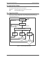
Trigger System Summary ............................................................................................ 132
7. Status Registers............................................................................................................... 134
7.1
Power-On Conditions ................................................................................................... 134
7.2
Operation Status Group ............................................................................................... 134
7.3
Questionable Status Group .......................................................................................... 137
7.4
Standard Event Status Group ....................................................................................... 138
7.5
Status Byte Register ................................................................................................... 138
7.6
Examples ................................................................................................................... 139
7.7
SCPI Command Completion......................................................................................... 140
8. i Series Controller Compatability .................................................................................... 141
8.1
Introduction................................................................................................................. 141
8.2
Trigger Subsystem ...................................................................................................... 141
8.3
Measurement Calibration Subsystem............................................................................ 142
8.4
Detecting i Series Controller Versions ........................................................................... 143
8.5
Sample code .............................................................................................................. 144
9. Option Commands........................................................................................................... 145
9.1
Introduction................................................................................................................. 145
9.2
IEC 1000-4-11............................................................................................................. 146
9.3
IEC 1000-4-13............................................................................................................. 150
9.4
RTCA/DO-160D........................................................................................................... 161
9.5
MIL-STD 704E ............................................................................................................ 167
9.6
OMNI OPTION ............................................................................................................ 169
Appendix A: SCPI Command tree.......................................................................................... 170
Appendix B: SCPI Conformance Information......................................................................... 176
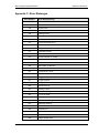
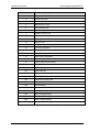
Appendix C: Error Messages.................................................................................................. 177
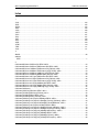
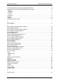
Index...................................................................................................................................... 179
4
May 2002
i Series / iX Series
SCPI Programming Manual-Rev L
California Instruments
Table of Figures
FIGURE 2-1 : PARTIAL COMMAND TREE ............................................................................................... 9
FIGURE 2-2 : COMMAND MESSAGE STRUCTURE................................................................................... 12
FIGURE 3-1 : RS232C INTERFACE CABLE W IRING DIAGRAM................................................................. 18
FIGURE 3-2 : DB9 TO DB25 ADAPTOR W IRING DIAGRAM..................................................................... 18
FIGURE 6-1 : OUTPUT TRANSIENT SYSTEM ........................................................................................ 119
FIGURE 6-2 : TRANSIENT TRIGGER SYSTEM MODEL ............................................................................ 123
FIGURE 6-3 : MEASUREMENT ACQUISITION TRIGGER MODEL.................................................................. 129
FIGURE 6-4 : PRE-EVENT AND POST-EVENT TRIGGERING...................................................................... 131
FIGURE 6-5 : TRIGGER SYSTEM BLOCK DIAGRAM................................................................................ 132
FIGURE 7-1 : STATUS SYSTEM MODEL ............................................................................................ 135
Table of Tables
TABLE 4-1 : PULS E:HOLD = WIDTH PARAMETERS ........................................................................... 81
TABLE 4-2 : PULS E:HOLD = DCYCLE PARAMETERS .......................................................................... 81
TABLE 5-1 : *RST DEFAULT PARAMETER VALUES .............................................................................. 108
TABLE 7-1 : OPERATION STATUS REGISTER...................................................................................... 134
TABLE 7-2 : CONFIGURATION OF STATUS REGISTER ........................................................................... 136
TABLE 7-3 : QUESTIONABLE STATUS REGISTER................................................................................. 137
TABLE 9-4 : ERROR MESSAGES .................................................................................................... 178
i Series / iX Series
May 2002
5
California Instruments
SCPI Programming Manual-Rev L
1. Introduction
This manual contains programming information for the i Series and iX Series AC/DC Power
Sources. This manual contains the following chapters:
Chapter 1
Introduction
Chapter 2
Introduction to SCPI
Chapter 3
System Considerations
Chapter 4
SCPI Command Reference
Chapter 5
Common Commands
Chapter 6
Programming Examples
Chapter 7
Status Registers
Chapter 8
i Series Controller Compatability
Chapter 9
Option Commands
Appendix A
SCPI command tree.
Appendix B
SCPI conformance information.
Appendix C
Error messages
1.1 Documentation Summary
This SCPI programming manual covers both the California Instruments i Series and ix Series
AC/DC power sources. A separate User Manual is also supplied with all models in this product
series. For front panel operation and general service and calibration information on these
produces, please refer to the User Manual. The programming manual covers issue related to
operating the i Series or ix Series remotely using an instrument controller.
The following documents are related to this Programming Manual and contain additional helpful
information for using these products in a remote control environment.
•
User's Guide. Includes specifications and supplemental characteristics, how to use the
front panel, how to connect to the instrument, and calibration procedures.
1.2 External References
SCPI References
The following documents will assist you with programming in SCPI:
•
Beginner's Guide to SCPI.
Highly recommended for anyone who has not had previous experience programming with SCPI.
IEEE-488 References
The most important IEEE-488 documents are your controller programming manuals -IEEE-488
Command Library for Windows ®, etc. Refer to these for all non-SCPI commands (for example:
Local Device Clear and Group Execute Trigger bus commands.)
•
IEEE-488
command library for Windows ®.
•
IEEE-488
controller programming
The following are two formal documents concerning the IEEE-488 interface:
6
May 2002
i Series / iX Series
SCPI Programming Manual-Rev L
California Instruments
•
ANSI/IEEE Std. 488.1-1987 IEEE Standard Digital Interface for Programmable
Instrumentation. Defines the technical details of the IEEE-488 interface. While much of the
information is beyond the need of most programmers, it can serve to clarify terms used in
this guide and in related documents.
•
ANSI/IEEE Std. 488.2-1987 IEEE Standard Codes, Formats, Protocols, and Common
Commands. Recommended as a reference only if you intend to do fairly sophisticated
programming. Helpful for finding precise definitions of certain types of SCPI message
formats, data types, or common commands.
The above two documents are available from the IEEE (Institute of Electrical and Electronics
Engineers), 345 East 47th Street, New York, NY 10017, USA.
1.3 Introduction to Programming
IEEE-488 Capabilities of the AC/DC Source
All AC/DC source functions are programmable over the IEEE-488 or RS232C interface bus.
The IEEE 488.2 capabilities of the AC/DC source are listed in appendix A of the User's Guide.
IEEE-488 Address
The AC/DC source operates from a single IEEE-488 address that may be set from the front
panel or programmatically through the IEEE-488 bus. To set the IEEE-488 address from the
front panel, select the Utility entry from the menu screen. Care must be used when setting the
IEEE-488 address programmatically since the next statement sent to the source must reflect
the new address.
i Series / iX Series
May 2002
7
California Instruments
SCPI Programming Manual-Rev L
2. Introduction to SCPI
SCPI (Standard Commands for Programmable Instruments) is a programming language for
controlling instrument functions over the IEEE-488. SCPI is layered on top of the hardwareportion of IEEE 488.1. The same SCPI commands and parameters control the same functions
in different classes of instruments. For example, you would use the same MEAS:VOLT?
command to measure the AC/DC source output voltage or the output voltage measured using a
SCPI-compatible multimeter.
2.1 Conventions Used in This Manual
Angle brackets<>
Items within angle brackets are parameter abbreviations. For
example, <NR1> indicates a specific form of numerical data.
Vertical bar
Vertical bars separate alternative parameters. For example, FIX |
STEP indicates that either "FIX" or "STEP" can be used as a
parameter.
Square Brackets[]
Items within square brackets are optional. The representation
[SOURce:]LIST means that SOURce: may be omitted.
Braces
Braces indicate parameters that may be repeated zero or more times.
It is used especially for showing arrays. The notation <A> <,B>
shows that parameter "A" must be entered, while parameter "B" may
be omitted or may be entered one or more times.
Boldface font
Boldface font is used to emphasize syntax in command definitions.
TRIGger:SOURCe<NRf> shows a command definition.
Computer font
Computer font is used to show program lines in text.
TRIGger:SOURCe INT
shows a program line.
2.2 The SCPI Commands and Messages
This paragraph explains the syntax difference between SCPI Commands and SCPI messages.
2.2.1 Types of SCPI Commands
SCPI has two types of commands, common and subsystem.
•
Common commands are generally not related to specific operations but to controlling
overall AC source functions such as reset, status and synchronization. All common
commands consist of a three-letter mnemonic preceded by an asterisk:
*RST
*IDN?
*SRE 256
•
Subsystem commands perform specific AC/DC source functions. They are organized into
an inverted tree structure with the "root" at the top. Some are single commands while
others are grouped within specific subsystems.
Refer to appendix A for the AC source SCPI tree structure.
8
May 2002
i Series / iX Series
SCPI Programming Manual-Rev L
California Instruments
2.2.2 Types of SCPI Messages
There are two types of SCPI messages, program and response.
•
A program message consists of one or more properly formatted SCPI commands sent
from the controller to the AC/DC source. The message, which may be sent at any time,
requests the AC/DC source to perform some action.
•
A response message consists of data in a specific SCPI format sent from the AC source
to the controller. The AC source sends the message only when commanded by a program
message called a "query."
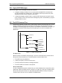
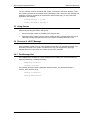
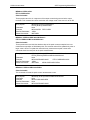
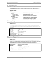
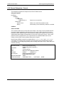
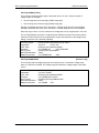
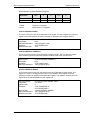
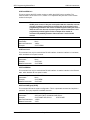
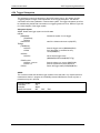
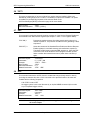
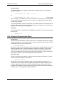
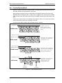
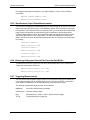
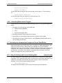
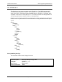
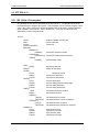
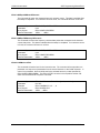
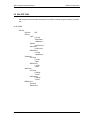
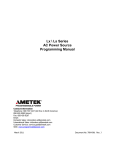
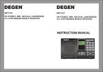
2.2.3 The SCPI Command Tree
As previously explained, the basic SCPI communication method involves sending one or more
properly formatted commands from the SCPI command tree to the instrument as program
messages. The following figure shows a portion of a subsystem command tree, from which you
access the commands located along the various paths (you can see the complete tree in
appendix A).
Root
:OUTPut
[:STATe]
:PON
:TTLTrg
[:STATe]
:SOURce
:STATus
:IMPedance
:REAL
:REACtive
:OPERation
[:EVEN]?
:CONDition?
Figure 2-1 : Partial Command Tree
The Root Level
Note the location of the ROOT node at the top of the tree. Commands at the root level are at
the top level of the command tree. The SCPI interface is at this location when:
•
The AC/DC source is powered on
•
A device clear (DCL) is sent to the AC source
•
The SCPI interface encounters a message terminator
•
The SCPI interface encounters a root specifier
Active Header Path
In order to properly traverse the command tree, you must understand the concept of the active
header path. When the AC/DC source is turned on (or under any of the other conditions listed
above), the active path is at the root. That means the SCPI interface is ready to accept any
command at the root level, such as SOURCe or MEASurement
i Series / iX Series
May 2002
9
California Instruments
SCPI Programming Manual-Rev L
If you enter SOURCe the active header path moves one colon to the right. The interface is now
ready to accept :VOLTage :FREQuency, or :CURRent as the next header. You must include
the colon, because it is required between headers.
If you now enter :VOLTage, the active path again moves one colon to the right. The interface is
now ready to accept either :RANGe or :LEVel as the next header.
If you now enter :RANGe you have reached the end of the command string. The active header
path remains at :RANGe If you wished, you could have entered :RANGe 135 ;LEVel 115 and
it would be accepted as a compound message consisting of:
SOURce:VOLTage:RANGe 135.
SOURce:VOLTage:LEVel 115.
The entire message would be:
SOURce:VOLTage:RANGe 135;LEVel 115
The message terminator after LEVel 115 returns the path to the root.
The Effect of Optional Headers
If a command includes optional headers, the interface assumes they are there. For example, if
you enter [SOURCe]:VOLTage 115, the interface recognizes it as [SOURce]:VOLTage:LEVel
115. This returns the active path to the root (:VOLTage). But if you enter
[SOURce]:VOLTage:LEVel 115 then the active path remains at :LEVel This allows you to send
[SOURce]:VOLTage:LEVel 115;RANGe 135
in one message. If you did not send LEVel you are allowed to send the following command:
[SOURce]:VOLTage 115;FREQuency 60
The optional header [SOURce] precedes the current, frequency, function, phase, pulse, list,
and voltage subsystems. This effectively makes :CURRent,:FREQuency, :FUNCtion, :PHASe,
:PULse, :LIST, and :VOLTage root-level commands.
Moving Among Subsystems
In order to combine commands from different subsystems, you need to be able to restore the
active path to the root. You do this with the root specifier (:). For example, you could open the
output relay and check the status of the Operation Condition register as follows:
OUTPut:STATe ON
STATus:OPERation:CONDition?
Because the root specifier resets the command parser to the root, you can use the root
specifier and do the same thing in one message:
OUTPut on; :STATus:OPERation:CONDition?
The following message shows how to combine commands from different subsystems as well
as within the same subsystem:
VOLTage:RANGe 135;LEVel
115;:CURRent 10;PROTection:STATe ON
Note the use of the optional header LEVel to maintain the correct path within the voltage and
current subsystems and the use of the root specifier to move between subsytems. The
"Enhanced Tree Walking Implementation" given in appendix A of the IEEE 488.2 standard is
not implemented in the AC/DC source.
Including Common Commands
10
May 2002
i Series / iX Series
SCPI Programming Manual-Rev L
California Instruments
You can combine common commands with system commands in the same message. Treat
the common command as a message unit by separating it with a semicolon (the message unit
separator). Common commands do not affect the active header path; you may insert them
anywhere in the message.
VOLTage:TRIGger 7.5;*TRG
OUTPut OFF;OUTPut ON;*RCL 2
2.3 Using Queries
Observe the following precautions with queries:
•
Set up the proper number of variables for the returned data.
•
Read back all the results of a query before sending another command to the AC source.
Otherwise a Query Interrupted error will occur and the unreturned data will be lost.
2.4 Structure of a SCPI Message
SCPI messages consist of one or more message units ending in a message terminator. The
terminator is not part of the syntax, but implicit in the way your programming language
indicates the end of a line (such as a newline or end-of-line character).
2.4.1 The Message Unit
The simplest SCPI command is a single message unit consisting of a command header (or
keyword) followed by a message terminator.
FREQuency?<newline>
VOLTage?<newline>
The message unit may include a parameter after the header. The parameter usually is
numeric, but it can be a string:
VOLTage 20<newline>
VOLTage MAX<newline>
i Series / iX Series
May 2002
11
California Instruments
SCPI Programming Manual-Rev L
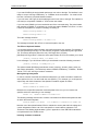
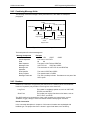
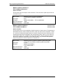
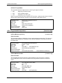
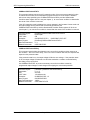
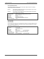
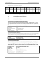
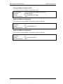
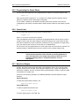
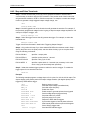
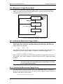
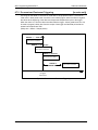
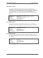
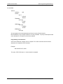
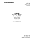
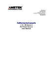
2.4.2 Combining Message Units
The following command message is briefly described here, with details in subsequent
paragraphs.
Data
Message Unit
Query Indicator
Headers
VOLT : LEV 80 ; RANG 135 ; : CURR? <NL>
Header
Separator
Message
Unit
Message
Terminator
Root Specifier
Separator
Figure 2-2 : Command Message Structure
The basic parts of the above message are:
Message Component
Headers
Header Separator
Data
Data Separator
Message Units
Message Unit
Separator
Root Specifier
Query Indicator
Message Terminator
Example
VOLT LEV
PROT
CURR
The colon in VOLT:LEV
80
88
The space in VOLT 80 and PROT 88
VOLT:LEV 80
PROT 88 CURR?
The semicolons in VOLT:LEV 80; and PROT 88;
The colon in PROT 88;:CURR?
The question mark in CURR?
The <NL> (newline) indicator. Terminators are not part of the
SCPI syntax
2.4.3 Headers
Headers are instructions recognized by the AC/DC source. Headers (which are sometimes
known as "keywords") may be either in the long form or the short form.
Long Form
The header is completely spelled out, such as VOLTAGE,
STATUS, and OUTPUT.
Short Form
The header has only the first three or four letters, such as
VOLT, STAT, and OUTP.
The SCPI interface is not sensitive to case. It will recognize any case mixture, such as
TRIGGER, Trigger, TRIGger. Short form headers result in faster program execution.
Header Convention
In the command descriptions in chapter 4 of this manual, headers are emphasized with
boldface type. The proper short form is shown in upper-case letters, such as DELay.
12
May 2002
i Series / iX Series
SCPI Programming Manual-Rev L
California Instruments
Header Separator
If a command has more than one header, you must separate them with a colon (VOLT:LEVel
OUTPut:RELay ON).
Optional Headers
The use of some headers is optional. Optional headers are shown in brackets, such as
OUTPut[:STATe] ON. As previously explained under "The Effect of Optional Headers", if you
combine two or more message units into a compound message, you may need to enter the
optional header.
2.4.4 Query Indicator
Following a header with a question mark turns it into a query (VOLTage?, VOLTage:RANGe?).
If a query contains a parameter, place the query indicator at the end of the last header
(VOLTage:LEVel? MAX).
2.4.5 Message Unit Separator
When two or more message units are combined into a compound message, separate the units
with a semicolon (STATus:OPERation?;QUEStionable?).
2.4.6 Root Specifier
When it precedes the first header of a message unit, the colon becomes the root specifier. It
tells the command parser that this is the root or the top node of the command tree. Note the
difference between root specifiers and header separators in the following examples:
CURRent:PROTection:DELay .1
:CURRent:PROTection:DELay .1
CURRent:PROTection:DELay .1;:VOLTage 12.5
All colons are header separators
Only the first colon is a root
specifier
Only the third colon is a root
specifier
You do not have to precede root-level commands with a colon; there is an implied colon in front
of every root-level command.
2.4.7 Message Terminator
A terminator informs SCPI that it has reached the end of a message. Three permitted message
terminators are:
•
newline (<NL>), which is ASCII decimal 10 or hex 0A.
•
end or identify (<END>)
•
both of the above (<NL><END>).
In the examples of this manual, there is an assumed message terminator at the end of each
message. If the terminator needs to be shown, it is indicated as <NL> regardless of the actual
terminator character.
i Series / iX Series
May 2002
13
California Instruments
SCPI Programming Manual-Rev L
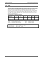
2.5 SCPI Data Formats
All data programmed to or returned from the AC source is in ASCII. The data type may be
numerical or character string.
2.5.1 Numerical Data Formats
Symbol
Data Form
Talking Formats
<NR1>
Digits with an implied decimal point assumed at the right of the
least-significant digit.
Example: 273
<NR2>
Digits with an explicit decimal point. Example:.0273
<NR3>
Digits with an explicit decimal point and an exponent.
Example: 2.73E+2
<Bool>
Boolean Data.
Example: 0 | 1 or ON | OFF
Listening Formats
<Nrf>
Extended format that includes <NR1>, <NR2> and <NR3>.
Examples: 273
273.0 2.73E2
<Nrf+>
Expanded decimal format that includes <Nrf> and MIN, MAX.
Examples: 273, 273.0, 2.73E2, MAX.
MIN and MAX are the minimum and maximum limit values that
are implicit in the range specification for the parameter.
<Bool>
Boolean Data
Example: 0 | 1
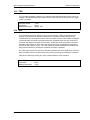
2.5.2 Character Data
Character strings returned by query statements may take either of the following forms,
depending on the length of the returned string:
14
<CRD>
Character Response Data. Permits the return of character strings.
<AARD>
Arbitrary ASCII Response Data. Permits the return of undelimited 7-bit ASCII.
This data type has an implied message terminator.
<SRD>
String Response Data. Returns string parameters enclosed in double quotes.
May 2002
i Series / iX Series
SCPI Programming Manual-Rev L
California Instruments
3. System Considerations
This chapter addresses some system issues concerning programming. These are AC/DC
Source addressing and the use of the following IEEE-488 system interface controllers:
•
National Instruments AT/GPIB-TNT controller with the Windows ® gpib-32.dll driver.
•
Hewlett Packard HP 82335A GP-IB Controller using the SICL driver library.
3.1 Assigning the IEEE-488 Address
The AC/DC source address can be set remotely or localy. All i and ix Series AC/DC source
are shipped with the IEEE-488 address set to 1 from the factory. Once the address is set, you
can assign it inside programs. Note that some PC IEEE-488 controller interface cards may
require you to run a setup utility to assign the AC/DC source address. In most cases however,
the instrument address can be set from the application program.
For systems using the National Instruments driver, the address of the IEEE-488 controller is
specified in the software configuration program located in the Windows 95® control panel. This
is not the instrument address. The controller often uses 0 as its own address so the use of 0
as an instrument address should be avoided. The AC/DC source address can be assigned
dynamically in the application program. (see the National Instruments GP-IB documentation
supplied with the controller card).
3.2 GPIB Controllers
The HP 82335A and National Instruments GP-IB are two popular GPIB controllers for the PC
platform. Each is briefly described here. See the software documentation supplied with the
controller card for more details.
3.2.1 HP 82335A Driver
The HP82335A supports the SICL instrument driver library which provides software
compatabilty accross all HP GPIB controllers. We recommend you use this driver to develop
your code.
The code fragment shown here illustrates the initilization of the interface to the ix Series or i
Series AC/DC source. The iopen call returns a unique device ID (Hpid) if the call is successful.
This ID should be used subsequently while communicating with the AC/DC source. The call to
the time out procedure ensures that the application program will time out after 1 sec if it is
unable to communicate with the instrument.
i Series / iX Series
May 2002
15
California Instruments
SCPI Programming Manual-Rev L
‘============ DECLARATION SECTION ===============================
Dim Source_Adr As Integer
'IEEE adress for L Series
Dim GPIB_Slot As Integer
'GPIB card slot nr.
Dim GPid As Integer
'Interface id for HPIB card
Dim Hpid As Integer
'Device id for HPIB SICL session
‘============ CODE SECTION ======================================
GPIB_Slot = 7
‘Determined by setup of IEEE controller
Hpid = 0
‘Clear session ID at program start
'Initialize HP-IB controller
Call iclear(GPIB_Slot)
If Hpid = 0 Then
Hpid = iopen("hpib" + CStr(GPIB_Slot) + "," + CStr(Source_Adr))
Call itimeout(Hpid, 1000)
End If
3.2.2 National Instruments GP-IB Driver
Your program must include the National Instruments header file for C programs or the
VBIB.BAS and VBIB-32.BAS modules for Visual Basic. If you are using LabView™ or
LabWindows™, make sure to select the correct controller when installing the IDE program.
Prior to running any applications programs, you must set up the GPIB controller hardware with
the configuration program located in the Windows 95 Control Panel. For plug and play versions
of the AT/GPIB-TNT, the setup will be performed when the card is first detected.
Regardless of the GPIB interface controller used, the power supply expects a message
termination on EOI or line feed, so set EOI w/last byte of Write. It is also recommended that
you set Disable Auto Serial Polling.
All function calls return the status word IBSTA%, which contains a bit (ERR) that is set if the
call results in an error. When ERR is set, an appropriate code is placed in variable IBERR%.
Be sure to check IBSTA% after every function call. If it is not equal to zero, branch to an error
handler that reads IBERR% to extract the specific error.
Error Handling
If there is no error-handling code in your program, undetected errors can cause unpredictable
results. This includes "hanging up" the controller and forcing you to reset the system. Both of
the above libraries have routines for detecting program execution errors.
Important: Use error detection throughout your application program.
16
May 2002
i Series / iX Series
SCPI Programming Manual-Rev L
California Instruments
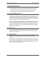
3.3 RS232C Interface
The RS232C interface can be used as an alternative to the IEEE-488 if no IEEE-488 controller
is available. A suitable cable to connect the AC/DC Source to a 9 pin PC-AT style serial port is
supplied with the source. If you are unable to locate this cable, you need to use a cable that
conforms to the wiring diagram shown in Figure 3-1.
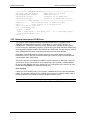
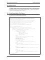
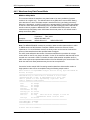
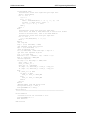
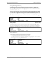
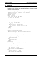
3.3.1 Serial Communication Test Program
The following sample program written in GW-BASIC can be used to check communication to
the i Series source over the RS232C serial interface.
'California Instruments i /ix Series RS232C Communication Demo Program
'(c) 1995 Copyright California Instruments, All Rights Reserved
'This program is for demonstration purposes only and is not to be
'used for any commercial application
'================================================================
'OPEN COM2. Replace with COM1, COM3 or COM4 for Com port used
'The input and output buffers are set to 2K each although
'this is not required for most operations.
OPEN "COM2:9600,n,8,1,BIN,TB2048,RB2048" FOR RANDOM AS #1
CLS
PRINT "**** INTERACTIVE MODE ****"
'Enter and endless loop to accept user entered commands
DO
INPUT "Enter AC Source Command ('quit' to exit)--> ", cmd$
IF cmd$ <> "QUIT" AND cmd$ <> "quit" THEN
PRINT #1, cmd$ + CHR$(10);
IF INSTR(cmd$, "?") THEN
PRINT #1, CHR$(4);
LINE INPUT #1, response$
PRINT response$
END IF
'Check for Errors after each command is issued
PRINT #1, "*ESR?" + CHR$(10);
PRINT #1, CHR$(4);
LINE INPUT #1, esr$
esr% = VAL(esr$) AND 60
IF esr% AND 4 THEN
PRINT "*** Query Error Reported by AC Source ***"
END IF
IF esr% AND 8 THEN
PRINT "*** Instrument Dependent Error Reported by AC Source
***"
END IF
IF esr% AND 16 THEN
PRINT "*** Command Execution Error Reported by AC Source
***"
END IF
IF esr% AND 32 THEN
PRINT "*** Command Syntax Error Reported by AC Source ***"
END IF
END IF
i Series / iX Series
May 2002
17
California Instruments
SCPI Programming Manual-Rev L
LOOP UNTIL cmd$ = "QUIT" OR cmd$ = "quit"
'Close COM port on exit
CLOSE #1
END
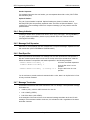
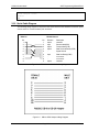
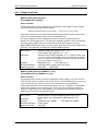
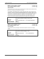
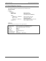
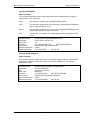
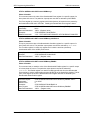
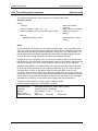
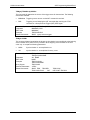
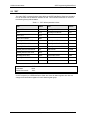
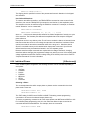
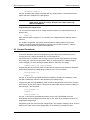
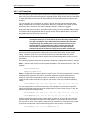
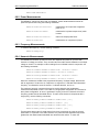
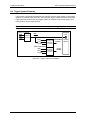
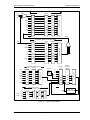
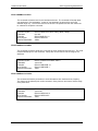
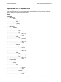
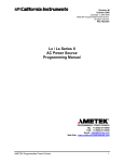
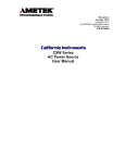
3.3.2 Serial Cable Diagram
The following wiring diagram is required for the serial interface cable between the AC/DC power
source and a PC communications port connector.
DB-9 PC
Pin
1
2
3
4
5
6
7
8
9
DB-9 AC Source
Pin
1
2
3
4
5
6
7
8
9
Direction
output
input
output
output
input
output
Description
reserved
Receive data(RxD)
Transmit data (TxD)
Data Terminal Ready (DTR)
Signal Ground
Data Set Ready (DSR)
no connect
no connect
reserved
Figure 3-1 : RS232C Interface Cable Wiring Diagram
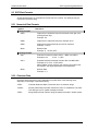
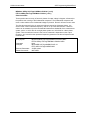
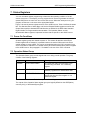
Figure 3-2 : DB9 to DB25 Adaptor Wiring Diagram
18
May 2002
i Series / iX Series
SCPI Programming Manual-Rev L
California Instruments
4. SCPI Command Reference
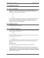
4.1 Introduction
Related Commands
Where appropriate, related commands or queries are included. These are listed because they
are either directly related by function, or because reading about them will clarify or enhance
your understanding of the original command or query.
Subsystem commands
Subsystem commands are specific to AC/DC source functions. They can be a single
command or a group of commands. The groups are comprised of commands that extend one
or more levels below the root. The description of common commands follows the description of
the subsystem commands.
The subsystem command groups are listed in alphabetical order and the commands within
each subsystem are grouped alphabetically under the subsystem. Commands followed by a
question mark (?) take only the query form. When commands take both the command and
query form, this is noted in the syntax descriptions.
IEEE 488.2 common commands
Common commands are defined by the IEEE-488.2 standard and are described in chapter 5 of
this manual.
i Series / iX Series
May 2002
19
California Instruments
SCPI Programming Manual-Rev L
4.2 Calibration Subsystem
The commands in this subsystem allow you to do the following:
•
Enable and disable the calibration mode
•
Calibrate the measured current and measured voltage and store new calibration in
nonvolatile memory.
•
Calibrate the current and voltage output levels, and store new calibration constants in
nonvolatile memory.
•
Calibrate the output impedance of the AC source, and store new calibration constants in
nonvolatile memory.
Subsystem Syntax
CALibrate
:PASSword
Allows entry of calibration password required to
change calibration coefficients
:MEASure
:CURRent
[:AMBient]
[:AC]
[:FSCale]
:DC
[:FSCale]
:ZERO
:TEMPerature
[:AC]
[:FSCale]
Ambient temperature calibrations
Calibrate full scale AC current measurements
Calibrate full scale DC current measurements
Cancel DC current measurements offset
Elevated temperature calibrations
Calibrate full scale AC current measurements at
higher temperature
:DC
[:FSCale]
:ZERO
:VOLTage
[:AMBient]
[:AC]
[:FSCale]
:DC
[:FSCale]
:ZERO
:TEMPerature
[:AC]
[:FSCale]
Calibrate full scale AC current measurements at
higher temperature
Cancel AC current measurements offset at a higher
temperature
Ambient temperature calibrations
Calibrate full scale AC voltage measurements
Calibrate full scale AC voltage measurements
Cancel AC voltage measurements offset
Elevated temperature calibrations
Calibrate full scale AC voltage measurements at
higher temperature
:DC
[:FSCale]
:ZERO
20
Calibrate full scale AC voltage measurements
Cancel AC voltage measurements offset
May 2002
i Series / iX Series
SCPI Programming Manual-Rev L
California Instruments
Subsystem Syntax (continued)
[:SOURce]
:PHASe
Calibrate output phase angle relative to external
sync.
:VOLTage
[:AC]
:LRANge
[:FSCale]
:ZERO
:HFRequency
:HRANge
[:FSCale]
:ZERO
:HFRequency
Calibrate full scale output voltage at low voltage
range
Trim output voltage offset at low voltage range.
Calibrate full scale output voltage at low voltage
range and high frequency.
Calibrate full scale output voltage at high voltage
range
Trim output voltage offset at high voltage range.
Calibrate full scale output voltage at high voltage
range and high frequency.
:DC
:LRANge
[:FSCale]
[:POSitive]
:NEGative
:ZERO
:HRANge
[:FSCale]
[:POSitive]
:NEGative
:ZERO
:IMPedance
:REAL
[:FSCale]
:ZERO
:REACtive
[:FSCale]
:ZERO
i Series / iX Series
Calibrate full scale output dc positive voltage at low
voltage range
Calibrate full scale output dc negative voltage at low
voltage range
Trim output dc voltage offset at low voltage range.
Calibrate full scale output dc positive voltage at high
voltage range
Calibrate full scale output dc negative voltage at high
voltage range
Trim output dc voltage offset at high voltage range.
Calibrate the real part of the programmable output
impedance at full scale value
Calibrate the real part of the programmable output
impedance at minimum value
Calibrate the reactive part of the programmable
output impedance at full scale value
Calibrate the reactive part of the programmable
output impedance at minimum value
May 2002
21
California Instruments
SCPI Programming Manual-Rev L
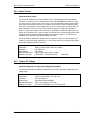
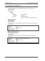
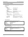
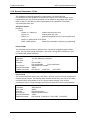
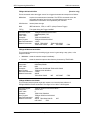
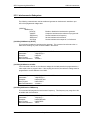
4.2.1 Password
CALibrate:PASSword
This command allows the entry of the calibration password. The calibration password is
required to use the data entry form of the calibration commands. Without the use of this
password, only the query form can be used to query any calibration coefficient but no new
calibration can be performed. Calibration queries always return two values. The first value is the
calibration coefficient itself, the second value is the temperature associated with that
coefficient. All temperate coefficients except for full scale AC voltage are computed by the
AC/DC power source controller.
The calibration password is defined as the numeric portion of the AC/DC power source serial
number spelled backwards. The password needs to be enclosed by single or double quotation
marks. Thus, if the units serial number is HK12345, the calibration password is “54321” and
the command syntax would be:
CAL:PASS “54321”
Note that any non-numeric characters such as the HK in the example shown here need to be
discarded when sending the calibration password. Only the numeric portion is to be used.
Command Syntax
Parameters
Examples
Related Commands
22
CALibrate:PASSword<SRD>
<numeric portion of serial number reversed> (default)
CAL:PASS '34593'
CAL:PASS "35461"
*IDN?
May 2002
i Series / iX Series
SCPI Programming Manual-Rev L
California Instruments
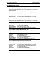
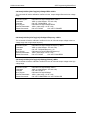
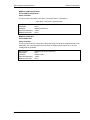
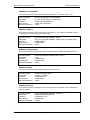
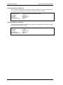
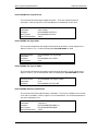
4.2.2 Measurement - Current
CALibrate:MEASure:CURRent[:AMBient][:AC][:FSCale] <NRf>
This command initiates the calibration of the AC current measurement at full scale and at
ambient temperature.
Command Syntax
Parameters
Examples
Query Syntax
Returned Parameters
Related Commands
CALibrate:MEASure:CURRent[:AMBient][:AC][:FSCale]
<NRf> (actual load current measured with external device)
CAL:MEAS:CURR 11.5
CALibrate:MEASure:CURRent?
<NR2> (value range -1000 to +1000)
CALibrate:MEASure:CURRent:TEMPerature[:AC][:FSCale]
CALibrate:MEASure:CURRent[:AMBient]:DC[:FSCale] <NRf>
This command initiates the calibration of the DC current measurement at full scale and at
ambient temperature.
Command Syntax
Parameters
Examples
Query Syntax
Returned Parameters
Related Commands
CALibrate:MEASure:CURRent[:AMBient]:DC[:FSCale]
<NRf> (actual load current measured with external device)
CAL:MEAS:CURR:DC 11.5
CALibrate:MEASure:CURRent:DC?
<NR2> (value range -1000 to +1000)
CALibrate:MEASure:CURRent:TEMPerature:DC[:FSCale]
CALibrate:MEASure:CURRent[:AMBient]:DC:ZERO <NRf>
This command initiates the offset adjustment of the DC current measurement at ambient
temperature.
Command Syntax
Parameters
Examples
Query Syntax
Returned Parameters
Related Commands
CALibrate:MEASure:CURRent[;AMBient]:DC:ZERO
<NRf> (0 or desired offset value)
CAL:MEAS:CURR:DC:ZERO
CALibrate:MEASure:CURRent:DC:ZERO?
<NR1> (value range -127 to +128)
CALibrate:MEASure:CURRent:TEMPerature:DC:ZERO
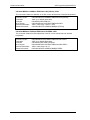
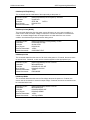
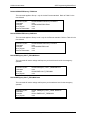
CALibrate:MEASure:CURRent:TEMPerature[:AC][:FSCale] <NRf>
This command initiates the calibration of the AC current measurement at full scale and at
elevated temperature.
Command Syntax
Parameters
Examples
Query Syntax
Returned Parameters
Related Commands
i Series / iX Series
CALibrate:MEASure:CURRent:TEMPerature[:AC][:FSCale]
<NRf> (actual load current measured with external device)
CAL:MEAS:CURR:TEMP 11.5
CALibrate:MEASure:CURRent:TEMP?
<NR1> (value range -1000 to +1000)
CALibrate:MEASure:CURRent[:AMB][:AC][:FSCale]
May 2002
23
California Instruments
SCPI Programming Manual-Rev L
CALibrate:MEASure:CURRent:TEMPerature:DC[:FSCale] <NRf>
This command initiates the calibration of the DC current measurement at elevated temperature.
Command Syntax
Parameters
Examples
Query Syntax
Returned Parameters
Related Commands
CALibrate:MEASure:CURRent:TEMPerature:DC[:FSCale]
<NRf> (0 or desired offset value)
CAL:MEAS:CURR:TEMP:DC
CALibrate:MEASure:CURRent:TEMPerature:DC?
<NR1> (value range -1000 to + 1000
CALibrate:MEASure:CURRent[:AMB]:DC[:FSCale]
CALibrate:MEASure:CURRent:TEMPerature:DC:ZERO <NRf>
This command initiates the offset adjustment of the DC current measurement at elevated
temperature.
Command Syntax
Parameters
Examples
Query Syntax
Returned Parameters
Related Commands
24
CALibrate:MEASure:CURRent:TEMPerature:DC:ZERO
<NRf> (0 or desired offset value)
CAL:MEAS:CURR:TEMP:DC:ZERO
CALibrate:MEASure:CURRent:TEMPerature:DC:ZERO?
<NR1> (value range 0 to +5)
CALibrate:MEASure:CURRent[:AMB]:DC:ZERO
May 2002
i Series / iX Series
SCPI Programming Manual-Rev L
California Instruments
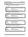
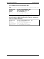
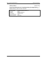
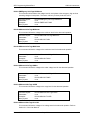
4.2.3 Measurement - Voltage
CALibrate:MEASure:VOLTage[:AMBient][:AC][:FSCale] <NRf>
This command initiates the calibration of the rms voltage measurement at full scale and at
ambient temperature.
Command Syntax
Parameters
Examples
Query Syntax
Returned Parameters
Related Commands
CALibrate:MEASure:VOLTage[:AMBient][:AC][:FSCale]
<NRf> (actual rms output voltage measured with external device)
CAL:MEAS:VOLT 120
CALibrate:MEASure:VOLTage?
<NR2> (value range -1000 to +1000)
CALibrate:MEASure:VOLTage:TEMPerature:[:AC][:FSCale]
CALibrate:MEASure:VOLTage[:AMBient]:DC[:FSCale] <NRf>
This command initiates the calibration of the DC voltage measurement at full scale and at
ambient temperature.
Command Syntax
Parameters
Examples
Query Syntax
Returned Parameters
Related Commands
CALibrate:MEASure:VOLTage[:AMBient]:DC[:FSCale]
<NRf> (actual DC output voltage measured with external device)
CAL:MEAS:VOLT:DC 120
CALibrate:MEASure:VOLTage:DC?
<NR2> (value range -1000 to +1000)
CALibrate:MEASure:VOLTage:TEMPerature:DC[:FSCale]
CALibrate:MEASure:VOLTage[:AMBient]:DC:ZERO <NRf>
This command initiates the offset adjustment of the DC voltage measurement at ambient
temperature.
Command Syntax
Parameters
Examples
Query Syntax
Returned Parameters
Related Commands
CALibrate:MEASure:VOLTage[:AMBient]:DC:ZERO
<NRf> (0 or desired offset value)
CAL:MEAS:VOLT:DC:ZERO 0
CALibrate:MEASure:VOLT:DC:ZERO?
<NR1> (value range -127 to +128)
CALibrate:MEASure:VOLTage:TEMPerature:DC:ZERO
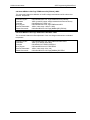
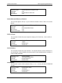
CALibrate:MEASure:VOLTage:TEMPerature[:AC][:FSCale] <NRf>
This command initiates the calibration of the rms voltage measurement at full scale and at
elevated temperature.
Command Syntax
Parameters
Examples
Query Syntax
Returned Parameters
Related Commands
i Series / iX Series
CALibrate:MEASure:VOLTage:TEMPerature[:AC][:FSCale]
<NRf> (actual rms output voltage measured with external device)
CAL:MEAS:VOLT:TEMP 120
CALibrate:MEASure:VOLTage:TEMPerature?
<NR2> (value range -1000 to +1000)
CALibrate:MEASure:VOLTage[:AMBient][:AC][:FSCale]
May 2002
25
California Instruments
SCPI Programming Manual-Rev L
CALibrate:MEASure:VOLTage:TEMPerature:DC[:FSCale] <NRf>
This command initiates the calibration of the DC voltage measurement at full scale and at
elevated temperature.
Command Syntax
Parameters
Examples
Query Syntax
Returned Parameters
Related Commands
CALibrate:MEASure:VOLTage:TEMPerature:DC[:FSCale]
<NRf> (actual DC output voltage measured with external device)
CAL:MEAS:VOLT:TEMP 120
CALibrate:MEASure:VOLTage:TEMPerature:DC?
<NR2> (value range -1000 to +1000)
CALibrate:MEASure:VOLTage[:AMBient]:DC[:FSCale]
CALibrate:MEASure:VOLTage:TEMPerature:DC:ZERO <NRf>
This command initiates the offset adjustment of the rms voltage measurement at elevated
temperature.
Command Syntax
Parameters
Examples
Query Syntax
Returned Parameters
Related Commands
26
CALibrate:MEASure:VOLTage:TEMPerature:DC:ZERO
<NRf> (0 or desired offset value)
CAL:MEAS:VOLT:TEMP:DC:ZERO 0
CALibrate:MEASure:VOLT:DC:ZERO?
<NR2> (value range -20 to +20)
CALibrate:MEASure:VOLTage[:AMBient]:DC:ZERO
May 2002
i Series / iX Series
SCPI Programming Manual-Rev L
California Instruments
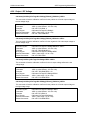
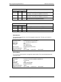
4.2.4 Output- Phase
CALibrate:PHASe <NRf+>
The i/iX Series AC/DC power source controller can be operated using its internal timebase
reference, an external clock or in external sync mode. (See FREQ:MODE command on page
58. When using in external clock or sync mode, it may be desirable to shift the phase output
with respect to the external reference. The feature may be used to create a deliberate phase
offset or to compensate for phase delays that may occur in the external sync signal path. The
phase calibration command can be used to program a negative or positive phase offset for
phase in degrees with respect to the external sync. Note that this calibration adjustment only
applies to the external clock or sync for phase A. Phase B and C are always programmed with
respect to phase A and their calibration offset is with respect to phase A. The phase to be
calibrated can be selected using the INST:NSEL command.
The phase offset is expressed in degrees and can range from -360.0 to +360.0 degrees. The
resolution of the phase angle adjustment (0.1°) is the same as the one for programming phase
angles (See [SOURce:]PHASe command).
Command Syntax
Parameters
Examples
Query Syntax
Returned Parameters
Related Commands
CALibrate:PHASe <NRf+>
<NRf> (a value between -360.0 and +360.0)
CAL:PHAS -2.3
CAL:PHAS?
<NR1> (value range -180.0 to +180.0)
FREQ:MODE [SOURce:]PHASe
INST:NSEL
4.2.5 Output- AC Voltage
CALibrate[:SOURce]:VOLTage[:AC]:LRANge[:FSCale] <NRf+>
This command will set the calibration coefficent for the AC full scale output voltage at the low
voltage range.
Command Syntax
Parameters
Examples
Query Syntax
Returned Parameters
Related Commands
i Series / iX Series
CALibrate:VOLTage:LRANge <NRf+>
<NRf> (a value between -127 and +128)
CAL:VOLT:LRAN -2
CALibrate:VOLTage:LRANge?
<NR1> (value range -127 to +128)
CAL:VOLT:LRAN:ZERO CAL:VOLT:LRAN:HFR
May 2002
27
California Instruments
SCPI Programming Manual-Rev L
CALibrate[:SOURce]:VOLTage[:AC]:LRANge:ZERO <NRf+>
This command will set the calibration coefficent for the output voltage offset at the low voltage
range.
Command Syntax
Parameters
Examples
Query Syntax
Returned Parameters
Related Commands
CALibrate:VOLTage:LRANge:ZERO <NRf+>
<NRf> (a value between -127 and +128)
CAL:VOLT:LRAN:ZERO +10
CALibrate:VOLTage:LRANge:ZERO?
<NR1> (value range -127 to +128)
CAL:VOLT:LRAN
CAL:VOLT:LRAN:HFR
CALibrate[:SOURce]:VOLTage[:AC]:LRANge:HFRequency <NRf+>
This command will set the calibration coefficent for the AC full scale output voltage at the low
voltage range and at high output frequency
Command Syntax
Parameters
Examples
Query Syntax
Returned Parameters
Related Commands
CALibrate:VOLTage:LRANge:HFRequency <NRf+>
<NRf> (a value between -127 and +128)
CAL:VOLT:LRAN:HFRequency +10
CALibrate:VOLTage:LRANge:HFRequency?
<NR1> (value range -127 to +128)
CAL:VOLT:LRAN
CAL:VOLT:LRAN:ZERO
CALibrate[:SOURce]:VOLTage[:AC]:HRANge[:FSCale] <NRf+>
This command will set the calibration coefficent for the AC full scale output voltage at the high
voltage range.
Command Syntax
Parameters
Examples
Query Syntax
Returned Parameters
Related Commands
28
CALibrate:VOLTage:HRANge <NRf+>
<NRf> (a value between -127 and +128)
CAL:VOLT:HRAN -2
CALibrate:VOLTage:HRANge?
<NR1> (value range -127 to +128)
CAL:VOLT:HRAN:ZERO CAL:VOLT:HRAN:HFR
May 2002
i Series / iX Series
SCPI Programming Manual-Rev L
California Instruments
CALibrate[:SOURce]:VOLTage[:AC]:HRANge:ZERO <NRf+>
This command will set the calibration coefficent for the output voltage offset at the high voltage
range.
Command Syntax
Parameters
Examples
Query Syntax
Returned Parameters
Related Commands
CALibrate:VOLTage:HRANge:ZERO <NRf+>
<NRf> (a value between -127 and +128)
CAL:VOLT:HRAN:ZERO +10
CALibrate:VOLTage:HRANge:ZERO?
<NR1> (value range -127 to +128)
CAL:VOLT:HRAN
CAL:VOLT:HRAN:HFR
CALibrate[:SOURce]:VOLTage[:AC]:HRANge:HFRequency <NRf+>
This command will set the calibration coefficent for the AC full scale output voltage at the high
voltage range and at high output frequency
Command Syntax
Parameters
Examples
Query Syntax
Returned Parameters
Related Commands
i Series / iX Series
CALibrate:VOLTage:HRANge:HFRequency <NRf+>
<NRf> (a value between -127 and +128)
CAL:VOLT:HRAN:HFRequency +10
CALibrate:VOLTage:HRANge:HFRequency?
<NR1> (value range -127 to +128)
CAL:VOLT:HRAN:ZERO CAL:VOLT:HRAN
May 2002
29
California Instruments
SCPI Programming Manual-Rev L
4.2.6 Output - DC Voltage
CALibrate[:SOURce]:VOLTage:DC:LRANge[:FSCale] [:POSitive] <NRf+>
This command will set the calibration coefficent for the positive dc full scale output voltage at
the low voltage range.
Command Syntax
Parameters
Examples
Query Syntax
Returned Parameters
Related Commands
CALibrate:VOLTage:DC:LRANge <NRf+>
<NRf> (a value between -127 and +128)
CAL:VOLT:DC:LRAN -2
CALibrate:VOLTage:DC:LRANge?
<NR1> (value range -127 to +128)
CAL:VOLT:DC:LRAN:NEG
CALibrate[:SOURce]:VOLTage:DC:LRANge[:FSCale] :NEGative <NRf+>
This command will set the calibration coefficent for the negative dc full scale output voltage at
the low voltage range.
Command Syntax
Parameters
Examples
Query Syntax
Returned Parameters
Related Commands
CALibrate:VOLTage:DC:LRANge:NEGative <NRf+>
<NRf> (a value between -127 and +128)
CAL:VOLT:DC:LRAN:NEG -2
CALibrate:VOLTage:DC:LRANge:NEG?
<NR1> (value range -127 to +128)
CAL:VOLT:DC:LRAN
CALibrate[:SOURce]:VOLTage:DC:LRANge:ZERO <NRf+>
This command will set the calibration coefficent for the dc output voltage offset at the low
voltage range.
Command Syntax
Parameters
Examples
Query Syntax
Returned Parameters
Related Commands
CALibrate:VOLTage:DC:LRANge:ZERO <NRf+>
<NRf> (a value between -127 and +128)
CAL:VOLT:DC:LRAN:ZERO +10
CALibrate:VOLTage:DC:LRANge:ZERO?
<NR1> (value range -127 to +128)
CAL:VOLT:DC:LRAN:ZERO
CALibrate[:SOURce]:VOLTage:DC:HRANge[:FSCale] [:POSitive] <NRf+>
This command will set the calibration coefficent for the positive dc full scale output voltage at
the high voltage range.
Command Syntax
Parameters
Examples
Query Syntax
Returned Parameters
Related Commands
30
CALibrate:VOLTage:DC:HRANge <NRf+>
<NRf> (a value between -127 and +128)
CAL:VOLT:DC:HRAN -2
CALibrate:VOLTage:DCHRANge?
<NR1> (value range -127 to +128)
CAL:VOLT:DC:LRAN:ZERO
May 2002
i Series / iX Series
SCPI Programming Manual-Rev L
California Instruments
CALibrate[:SOURce]:VOLTage:DC:HRANge[:FSCale]:NEGative <NRf+>
This command will set the calibration coefficent for the negative dc full scale output voltage at
the high voltage range.
Command Syntax
Parameters
Examples
Query Syntax
Returned Parameters
Related Commands
CALibrate:VOLTage:DC:HRANge:[FSCale]:NEGative <NRf+>
<NRf> (a value between -127 and +128)
CAL:VOLT:DC:LRAN:NEG -2
CALibrate:VOLTage:DC:LRANge:NEG?
<NR1> (value range -127 to +128)
CAL:VOLT:DC:HRAN:ZERO
CALibrate[:SOURce]:VOLTage:DC:HRANge:ZERO <NRf+>
This command will set the calibration coefficent for the dc output voltage offset at the high
voltage range.
Command Syntax
Parameters
Examples
Query Syntax
Returned Parameters
Related Commands
i Series / iX Series
CALibrate:VOLTage:DC:HRANge:ZERO <NRf+>
<NRf> (a value between -127 and +128)
CAL:VOLT:DC:HRAN:ZERO +10
CALibrate:VOLTage:DC:HRANge:ZERO?
<NR1> (value range -127 to +128)
CAL:VOLT:DC:LRAN
May 2002
31
California Instruments
SCPI Programming Manual-Rev L
4.2.7 Output- Impedance
CALibrate[:SOURce]:REAL[:FSCale] <Nrf+>
This command will set the calibration coefficent for the real part of the output impedance.
Command Syntax
Parameters
Examples
Query Syntax
Returned Parameters
Related Commands
CALibrate[:SOURce]:REAL[:FSCale] <NRf+>
<NRf> (a value between 0 and +100)
CAL:REAL +10
CALibrate[:SOURce]:REAL[:FSCale]?
<NR1> (value range 0 to +100)
CALibrate[:SOURce]:REACtive[:FSCale]
CALibrate[:SOURce]:REAL:ZERO <Nrf+>
This command will set the lowest real part of the output impedance that could be programmed.
Command Syntax
Parameters
Examples
Query Syntax
Returned Parameters
Related Commands
CALibrate[:SOURce]:REAL:ZERO <NRf+>
<NRf> (a value between 0 and +100)
CAL:REAL:ZERO 100
CALibrate[:SOURce]:REAL:ZERO?
<NR1> (value range 0 to +100)
CALibrate[:SOURce]:REACtive:ZERO
CALibrate[:SOURce]:REACtive[:FSCale] <Nrf+>
This command will set the calibration coefficent for the reactive part of the output impedance.
Command Syntax
Parameters
Examples
Query Syntax
Returned Parameters
Related Commands
CALibrate[:SOURce]:REACtive[:FSCale] <NRf+>
<NRf> (a value between 0 and +300)
CAL:REAL +10
CALibrate[:SOURce]:REACtive[:FSCale]?
<NR1> (value range 0 to +300)
CALibrate[:SOURce]:REAL[:FSCale]
CALibrate[:SOURce]:REACtive:ZERO <Nrf+>
This command will set the lowest reactive part of the output impedance that could be
programmed.
Command Syntax
Parameters
Examples
Query Syntax
Returned Parameters
Related Commands
32
CALibrate[:SOURce]:REACtive:ZERO <NRf+>
<NRf> (a value between 0 and +300)
CAL:REACtive:ZERO 100
CALibrate[:SOURce]:REACtive:ZERO?
<NR1> (value range 0 to +300)
CALibrate[:SOURce]:REAL:ZERO
May 2002
i Series / iX Series
SCPI Programming Manual-Rev L
California Instruments
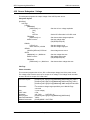
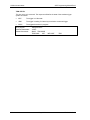
4.3 Instrument Subsystem
The Instrument subsystem controls the phase mode of the AC/DC power source for
configurations capable of operating in three phase mode.
Subsystem Syntax
INSTrument
COUPle ALL | NONE
:NSELect 1 | 2 | 3
:SELect A | B | C
Couples or uncouples commands
Selects phase A, B or C using numeric references
Selects phase A, B or C using character references
INSTrument:COUPle
This command may be used to couple all output phase in three phase mode. When the
phases are coupled, commands issues subsequently affect all three phases. This allows the
output voltage to be programmed for all three phases using a single command and without the
need to select each phase individually. When uncoupled, commands issued must be
preceeded by the PHAS:NSEL command and will only affect the selected command.
Available parameters are ALL to couple all phases and NONE to uncouple all phases. In single
phase mode, the INST:COUP commands are ignored.
Command Syntax
Parameters
Examples
Query Syntax
Returned Parameters
Related Commands
INSTrument:COUPle
ALL | NONE
INST:COUP ALL
INST:COUP?
<CRD>
INST:NSEL
INST:SEL
INSTrument:NSELect
This command may be used select a specific output phase in three phase mode using a
numeric reference. A 1 denotes phase A, a 2 denotes phase B and a 3 denotes Phase C. As
long as the instrument state is coupled however, programming command will affect all phases.
As soon as the INST:COUP NONE command is issued, the last selected phase becomes
selected. To immediately change the output of a single phase only, make sure the instrument
state is uncoupled when issuing the INST:NSEL command.
Note that the MEASuse and FETCh subsystems are not affected by the INST:COUP
command and always operate on the selected phase only. This means the instrument can
remain in coupled mode while doing measurement queries using “INST:NSEL
<n>;FETC:VOLT?;*WAI”. Note that when the instrument is subsequently put in the
uncoupled state using “INST:COUP NONE”, the last issued phase selection will be in effect.
To make sure the desired phase is selected, follow the “INST:COUP NONE” command with
an “INST:NSEL <n>” command
Command Syntax
Parameters
Examples
Query Syntax
Returned Parameters
Related Commands
i Series / iX Series
INSTrument:NSEL
1|2|3
INST:NSEL 1
INST:NSEL?
<CRD>
INST:COUP
INST:SEL
May 2002
33
California Instruments
SCPI Programming Manual-Rev L
INSTrument:SELect
This command may be used select a specific output phase in three phase mode using a
character reference. “A” denotes phase A, “B” denotes phase B and “C” denotes Phase C. As
long as the instrument state is coupled however, programming command will affect all phases.
As soon as the INST:COUP NONE command is issued, the last selected phase becomes
selected. To immediately change the output of a single phase only, make sure the instrument
state is uncoupled when issuing the INST:SEL command.
Note that the MEASuse and FETCh subsystems are not affected by the INST:COUP
command and always operate on the selected phase only. This means the instrument can
remain in coupled mode while doing measurement queries using “INST:SEL
<n>;FETC:VOLT?;*WAI”. Note that when the instrument is subsequently put in the
uncoupled state using “INST:COUP NONE”, the last issued phase selection will be in effect.
To make sure the desired phase is selected, follow the “INST:COUP NONE” command with
an “INST:SEL <n>” command
Command Syntax
Parameters
Examples
Query Syntax
Returned Parameters
Related Commands
34
INSTrument:SEL
A|B|C
INST:SEL A
INST:SEL?
<CRD>
INST:COUP
INST:NSEL
May 2002
i Series / iX Series
SCPI Programming Manual-Rev L
California Instruments
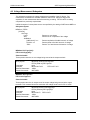
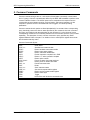
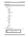
4.4 Array Measurement Subsystem
[iX series only]
This command subsystem lets you retrieve arrays containing measurement data. Only current
and voltage measurements are stored in an array. Two measurement commands are available:
MEASure and FETCh. A MEASure command triggers the acquisition of new data before
returning the readings from the array. A FETCh command returns previously acquired data from
the array.
Individual outputs of a three-phase source are specified by the setting of INSTrument:NSELect.
Subsystem Syntax
MEASure | FETCh
:ARRay
:CURRent
[:DC]?
:HARMonic
[:AMPLitude]?
:PHASe?
:MODE
:VOLTage
[:DC]?
:HARMonic
[:AMPLitude]?
:PHASe?
i Series / iX Series
Returns the digitized instantaneous current
Returns amplitudes of the first 50 harmonics
Returns phase angles of the first 50 harmonics
Selects waveform data transfer format
Returns the digitized instantaneous voltage
Returns amplitudes of the first 50 harmonics
Returns phase angles of the first 50 harmonics
May 2002
35
California Instruments
SCPI Programming Manual-Rev L
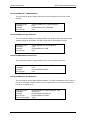
4.4.1 Current Array Data
MEASure:ARRay:CURRent[:DC]?
FETCh:ARRay:CURRent[:DC]?
Phase Selectable
These queries return an array containing the instantaneous output current in amperes. The
data returned in arbitrary block data format as follows:
#5<block length n><b0><b1><b2><b3>.....<bn-3><bn -2><bn-1><bn>
where b0,b1,b2,b3 are four hex bytes represent IEEE single precision floating number, where
b0 is the most significant byte and b3 is the least significant byte.
The output voltage and current are digitized whenever a measure command is given or
whenever an acquire trigger occurs. The time interval between samples is 25 .6 microseconds
for a single phase system and 76.8 microseconds for three phase system. The query
SENSe:SWEep:TINTerval? will return the time interval, the position of the trigger relative to the
beginning of the data buffer is determined by SENSe:SWEep:OFFSet.
Query Syntax
Parameters
Examples
Returned Parameters
Related Commands
36
MEASure:ARRay:CURRent[:DC]? [<n>,<n>]
FETCh:ARRay:CURRent[:DC]? [<n>,<n>]
Optional block and offset parameters <n>,<n>. Where the first value
<n> is the number of 256 sample blocks to transfer and the second
value <n> is the first block (offset) to start with. Number of blocks is
from 1 to 16, offset is from 0 to 15.
MEAS:ARR:CURR?
FETC:ARR:CURR? 4,0
4096 data points in arbitrary block data format
INST:NSEL
SENS:SWE
May 2002
i Series / iX Series
SCPI Programming Manual-Rev L
California Instruments
MEASure:ARRay:CURRent:HARMonic? [<nrf>]
FETCh:ARRay:CURRent:HARMonic? [<nrf>]
Phase Selectable
These queries return an array of harmonic amplitudes of output current in rms amperes. The
first value returned is the dc component, the second value is the fundamental frequency, and
so on up to the 50th harmonic. Harmonic orders can be measured up to the fundamental
measurement bandwidth of the measurement system, which is 19.531 kHz for a single phase
system and 6.510kHz for a three phase system. Thus, the maximum harmonic that can be
measured is dependent on the output frequency. Any harmonics that represent frequencies
greater than the above frequencies are returned as 0.
The total number of harmonic values returned may be specified as a parameter to the query
command. Only harmonic data values from 0 (dc) to the number specified will be returned. This
capability may be used to reduce the transfer time by avoiding the transfer of unwanted data. If
the fundamental frequency is programmed to 400 Hz for example, there is no need to query
harmonics above number
Query Syntax
Parameters
Examples
Returned Parameters
Related Commands
i Series / iX Series
MEASure:ARRay:CURRent:HARMonic[:AMPLitude]? [<nrf>]
FETCh:ARRay:CURRent:HARMonic[:AMPLitude]?
None
MEAS:ARR:CURR:HARM?
FETC:ARR:CURR:HARM? 20
21 NR2 values
INST:NSEL
May 2002
37
California Instruments
SCPI Programming Manual-Rev L
MEASure:ARRay:CURRent:HARMonic:PHASe? [<nrf>]
FETCh:ARRay:CURRent:HARMonic:PHASe? [<nrf>]
Phase Selectable
These queries return an array of harmonic phases of output current in degrees, referenced to
the positive zero crossing of the fundamental component. The fundamental component will
return a value relative to the fundamental voltage.
The first value returned is the dc component (always returned as 0 degrees phase) , the
second value is the fundamental frequency, and so on up to the 50th harmonic. Harmonic
orders can be measured up to the fundamental measurement bandwidth of the measurement
system, which is 19.531 kHz for a single phase system and 6.510kHz for a three phase
system. Thus the maximum harmonic that can be measured is dependent on the output
frequency. Any harmonics that represent frequencies greater than the above frequencies are
returned as 0.
Query Syntax
Parameters
Examples
Returned Parameters
Related Commands
38
MEASure:ARRay:CURRent:HARMonic:PHASe?<NRf>
FETCh:ARRay:CURRent:HARMonic:PHASe?<NRf>
None
MEAS:ARR:CURR:HARM:PHAS? 16
FETC:ARR:CURR:HARM:PHAS?
17 NR2 values
INST:NSEL
May 2002
i Series / iX Series
SCPI Programming Manual-Rev L
California Instruments
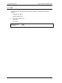
4.4.2 Waveform Array Data Format Mode
MEASure:ARRay:MODe
This command selects the waveform array data format to be used. (Available in firmware
revision 2.32 or higher only.) The default mode is binary (BIN) which uses an IEEE floating
point data format in which each data sample is transferred as a 4 byte floating point binary
data word. Alternatively, an ASCII format may be selected (ASCii) in which each data sample
is sent as 8 ASCII Hex values representing the 4 byte IEEE floating point data. Note that the
transfer mode only applies to MEAS:ARR:VOLT and MEAS:ARR:CURR queries. All other
measurement queries always return ASCII data. Note that at power on, the default mode is
always set to binary (BIN).
Syntax
Examples
Related Commands
MEASure:ARRay:MODe
Parameters
BIN | ASCii
MEAS:ARR:MOD ASC
MEAS:ARR:VOLT
MEAS:ARR:CURR
Note: The MEAS:ARR:MOD command is provided to allow waveform data transfers in ASCII
on DBCS versions of MS Windows. Examples of DBCS versions are Chinese, Korean,
Japanese etc. On most Windows versions, the binary mode can be used as it reduces the
amount of data transferred and thus provides better throughput.
The ASCII mode will double the number of characters transferred so provisions for a larger
receive buffer on the PC may have to be made. On the iX, the maximum data size that can be
sent with one command is 16KB. To transfer the entire 4096 waveform acquisition buffer in
ASCII mode requires two separate data transfers of the first followed by the second buffer. The
block size and block offset parameters may be used to accomplish this.
Conversion function sample VB6. Converting waveform data from either transfer mode to a
single precision value can be accomplished using the following sample routine:
Public Function StringToIEEEFloat(ByVal sData As String, ByVal bAsciiMode As
Boolean) As Single
'=============================================================
'bAsciiMode flag is used if data is received as 8 ascii chars
'representing Hex 0-9,A-F. If bAsciiMode flag is false, then
'data is process as 4 char representing a byte each. Ascii
'mode is needed for DCBS windows
'=============================================================
Dim i
As Integer
Dim j
As Integer
Dim iChar
As Integer
Dim expo
As Long
Dim mantisse As Long
Dim expo_val As Variant
Dim mant_f
As Single
Dim c(3)
As Long
'Must use 32 bit integers to allow for
'intermediate result of 24 bit shift
Dim sign
As Boolean
'=============================================================
Const MANT_MAX = &H7FFFFF
Const EXPO_MAX = 2 ^ 126
'=============================================================
On Error GoTo FloatConvError
i Series / iX Series
May 2002
39
California Instruments
SCPI Programming Manual-Rev L
If bAsciiMode Then
'Retrieve ASC values from eight hex byte input data
sData = UCase(sData)
For i = 0 To 3
c(i) = 0
For j = 0 To 1
iChar = AscB(Mid$(sData, i * 2 + j + 1, 1)) - 48
If iChar > 9 Then iChar = iChar - 7
c(i) = c(i) * 16 * j + iChar
Next j
Next i
Else
'Retrieve ASC values from four byte input data
'Note: Don't use ASCB or ASCW functions as results will differ
'based on character sets, even on non DCBS Windows
'Retrieve ASC values from four byte input data
For i = 0 To 3
c(i) = Asc(Mid$(sData, i + 1, 1))
Next i
End If
'Get sign bit
sign = ((c(0) And &H80) = &H80)
'Get exponent value less sign bit
expo = (c(0) And &H7F) * 2
'Pick up exponent sign
If (c(1) And &H80) = &H80 Then expo = expo Or 1
'get data less exponent sign bit
c(1) = c(1) And &H7F
mantisse = c(1) * &H10000 + c(2) * &H100 + c(3)
mant_f = mantisse / MANT_MAX
'Process exponent
If (expo <> 0) And (expo <> &HFF) Then
expo = expo - 127
mant_f = mant_f + 1
expo_val = 2 ^ Abs(expo)
If (expo > 0) Then mant_f = mant_f * expo_val
If (expo < 0) Then mant_f = mant_f / expo_val
Else
If (mant_f <> 0) Then
If expo = 0 Then
mant_f = mant_f / EXPO_MAX
Else
mant_f = mant_f * EXPO_MAX
End If
End If
End If
'Append number sign and return value
If sign Then mant_f = -mant_f
StringToIEEEFloat = mant_f
Exit Function
'=============================================================
FloatConvError:
'Conversion errors are truncated to zero
StringToIEEEFloat = 0
Exit Function
End Function
40
May 2002
i Series / iX Series
SCPI Programming Manual-Rev L
California Instruments
4.4.3 Voltage Array Data
MEASure:ARRay:VOLTage[:DC]?
FETCh:ARRay:VOLTage[:DC]?
Phase Selectable
These queries return an array containing the instantaneous output voltage in volts. The data
returned in arbitrary block data format as follows:
#5<block length n><b0><b1><b2><b3>.....<bn-3><bn -2><bn-1><bn>
where b0,b1,b2,b3 are four hex bytes represent IEEE single precision floating number, where
bo is the most significant byte and b3 is the least significant byte.
The output voltage and current are digitized whenever a measure command is given or
whenever an acquire trigger occurs. The time interval between samples is 25 .6 microseconds
for a single pahse system and 76.8 microseconds for three phase system. The query
SENSe:SWEep:TINTerval? will return the time interval, the position of the trigger relative to the
beginning of the data buffer is determined by SENSe:SWEep:OFFSet.
Query Syntax
Parameters
Examples
Returned Parameters
Related Commands
MEASure:ARRay:VOLTage[:DC]? [<n>, <n>]
FETCh:ARRay:VOLTage[:DC]? [<n>, <n>]
Optional block and offset parameters <n>,<n>. Where the first value
<n> is the number of 256 sample blocks to transfer and the second
value <n> is the first block (offset) to start with. Number of blocks is
from 1 to 16, offset is from 0 to 15.
MEAS:ARR:VOLT?
FETC:ARR:VOLT?
4096 data points in arbitrary block data format
INST:NSEL
SENS:SWE
MEASure:ARRay:VOLTage:HARMonic? [<nrf>]
FETCh:ARRay:VOLTage:HARMonic? [<nrf>]
Phase Selectable
These queries return an array of harmonic amplitudes of output voltage in rms volts. The first
value returned is the dc component, the second value is the fundamental frequency, and so on
up to the 50th harmonic. Harmonic orders can be measured up to the fundamental
measurement bandwidth of the measurement system, which is 19.53KHz for a single pahse
system and 6.51KHz for three phase system. Thus, the maximum harmonic that can be
measured is dependent on the output frequency. Any harmonics that represent frequencies
greater than above frequencies are returned as 0.
Query Syntax
Parameters
Examples
Returned Parameters
Related Commands
i Series / iX Series
MEASure:ARRay:VOLTage:HARMonic[:AMPLitude]? [<nrf>]
FETCh:ARRay:VOLTage:HARMonic[:AMPLitude]? [<nrf>]
None
MEAS:ARR:VOLT:HARM?
FETC:ARR:VOLT:HARM?
51 NR2 values
INST:NSEL
May 2002
41
California Instruments
SCPI Programming Manual-Rev L
MEASure:ARRay:VOLTage:HARMonic:PHASe? [<nrf>]
FETCh:ARRay:VOLTage:HARMonic:PHASe? [<nrf>]
Phase Selectable
These queries return an array of harmonic phases of output voltage in degrees, referenced to
the positive zero crossing of the fundamental component. The fundamental component will
return a value relative to the fundamental voltage for phase A. Phase A will return a zero value.
The first value returned is the dc component (always returned as 0 degrees phase) , the
second value is the fundamental frequency, and so on up to the 50th harmonic. Harmonic
orders can be measured up to the fundamental measurement bandwidth of the measurement
system, which is 19.531 kHz for a single phase system and 6.510kHz for a three phase
system. Thus the maximum harmonic that can be measured is dependent on the output
frequency. Any harmonics that represent frequencies greater than the above frequencies are
returned as 0.
Query Syntax
Parameters
Examples
Returned Parameters
Related Commands
42
MEASure:ARRay:VOLTage:HARMonic:PHASe?<NRf>
FETCh:ARRay:VOLTage:HARMonic:PHASe?<NRf>
None
MEAS:ARR:VOLTage:HARM:PHAS? 30
FETC:ARR:VOLTage:HARM:PHAS?
31 NR2 values
INST:NSEL
May 2002
i Series / iX Series
SCPI Programming Manual-Rev L
California Instruments
4.5 Current Measurement Subsystem
This subsystem programs the current measurement capability of the AC/DC source. Two
measurement commands are available: MEASure and FETCh.
•
MEASure triggers the acquisition of new measurement data before returning a reading.
•
FETCh returns a reading computed from previously acquired data.
Individual outputs of a three-phase source are specified by the setting of INSTrument:NSELect.
Subsystem Syntax
MEASure | FETCh
[:SCALar]
:CURRent
[:AC]?
:DC?
:AMPLitude
:MAX?
:RESet
:CREStfactor?
:HARMonic
[:AMPLitude]? <n>
:PHASe? <n>
:THD?
Returns ac rms current
Returns dc component of the current
Returns peak current
Reset the peak current measurements
Returns current crestfactor
Returns amplitude of the Nth harmonic of current
Returns phase of the Nth harmonic of current
Returns % of total harmonic distortion of current
MEASure:CURRent[:AC]?
FETCh:CURRent[:AC]?
Phase Selectable
These queries return the ac component rms current being sourced at the output terminals if the
voltage mode is set for AC only, and will return the AC plus the DC component if the voltage
mode is set for ACDC.
Query Syntax
Parameters
Examples
Returned Parameters
Related Commands
i Series / iX Series
MEASure[:SCALar]:CURRent[:AC]?
FETCh[:SCALar]:CURRent[:AC]?
None
MEAS:CURR:AC?
FETC:CURR?
<NR2>
INST:NSEL
May 2002
43
California Instruments
SCPI Programming Manual-Rev L
MEASure:CURRent:DC?
FETCh:CURRent:DC?
Phase Selectable
These queries return the dc component of the output current being sourced at the output
terminals. This command should be used when the voltage mode of the source is set for DC
Query Syntax
Parameters
Examples
Returned Parameters
Related Commands
MEASure[:SCALar]:CURRent:DC?
FETCh[:SCALar]:CURRent:DC?
None
MEAS:CURR? FETC:CURR?
<NR2>
INST:NSEL
MEASure:CURRent:AMPLitude:MAXimum?
FETCh:CURRent:AMPLitude:MAXimum?
Phase Selectable
These queries return and hold the absolute value of the peak current as sampled over one
measurement acquisition of 4096 data points. The returned value will be updated only when a
larger value is found. To update the value with every measurement a peak current reset
commnad should be used prior to the peak measurements.
Query Syntax
Parameters
Examples
Returned Parameters
Related Commands
MEASure[:SCALar]:CURRent:AMPLitude:MAXimum?
FETCh[:SCALar]:CURRent:AMPLitude:MAXimum?
None
MEAS:CURR:AMPL:MAX?
FETC:CURR:AMPL:MAX?
<NR2>
INST:NSEL
MEAS:CURR:AMPL:RESet
MEASure:CURRent:AMPLitude:RESet
Phase Selectable
This command will reset the peak current measurement to zero.
Query Syntax
Parameters
Examples
Returned Parameters
Related Commands
44
MEASure[:SCALar]:CURRent:AMPLitude:RESset.
None
MEAS:CURR:AMPL:RES
None
MEAS:CURR:AMPL:MAX?
May 2002
i Series / iX Series
SCPI Programming Manual-Rev L
California Instruments
MEASure:CURRent:CREStfactor?
FETCh:CURRent:CREStfactor?
Phase Selectable
These queries return the output current crest factor. This is the ratio of peak output current to
rms output current.
Query Syntax
Parameters
Examples
Returned Parameters
Related Commands
MEASure[:SCALar]:CURRent:CREStfactor?
FETCh[:SCALar]:CURRent:CREStfactor?
None
MEAS:CURR:CRES? FETC:CURR:CRES?
<NR2>
INST:NSEL
MEASure:CURRent:HARMonic?
FETCh:CURRent:HARMonic?
[ix series only]
[ix series only]
Phase Selectable
These queries return the rms amplitude of the Nth harmonic of output current. The parameter is
the desired harmonic number. Queries sent with a value of 0 return the dc component. A value
of 1 returns the fundamental output frequency. Harmonic frequencies can be queried up to the
fundamental measurement bandwidth of the measurement system, which is 19.531 kHz for a
single phase system and 6.510kHz for a three phase system. Thus the maximum harmonic
that can be measured is dependent on the output frequency. Any harmonics that represent
frequencies greater than above frequencies are returned as 0.
Query Syntax
Parameters
Examples
Returned Parameters
Related Commands
i Series / iX Series
MEASure[:SCALar]:CURRent:HARMonic[:AMPLitude]?<NRf>
FETCh[:SCALar]:CURRent:HARMonic[:AMPLitude]?<NRf>
0 to 50
MEAS:CURR:HARM? 3
FETC:CURR:HARM? 1
<NR2>
INST:NSEL
May 2002
45
California Instruments
SCPI Programming Manual-Rev L
MEASure:CURRent:HARMonic:PHASe?
FETCh:CURRent:HARMonic:PHASe?
[ix series only]
[ix series only]
Phase Selectable
These queries return the phase angle of the Nth harmonic of output current, referenced to the
positive zero crossing of the fundamental component.
The parameter is the desired harmonic number. Queries sent with a value of 0 return the dc
component. A value of 1 returns the fundamental output frequency. Harmonic orders can be
queried up to the fundamental measurement bandwidth of the measurement system, which is
19.531 kHz for a single phase system and 6.510kHz for a three phase system. Thus the
maximum harmonic that can be measured is dependent on the output frequency. Any
harmonics that represent frequencies greater than above frequencies are returned as 0.
Query Syntax
Parameters
Examples
Returned Parameters
Related Commands
MEASure[:SCALar]:CURRent:HARMonic:PHASe?<NRf>
FETCh[:SCALar]:CURRent:HARMonic:PHASe?<NRf>
0 to 50
MEAS:CURR:HARM:PHAS? 3 FETC:CURR:HARM:PHAS? 1
<NR2>
INST:NSEL
MEASure:CURRent:HARMonic:THD? ]
FETCh:CURRent:HARMonic:THD?
[ix series only]
[ix series only]
Phase Selectable
These queries return the percentage of total harmonic distortion and noise in the output
current.
Query Syntax
Parameters
Examples
Returned Parameters
Related Commands
46
MEASure[:SCALar]:CURRent:HARMonic:THD?
FETCh[:SCALar]:CURRent:HARMonic:THD?
None
MEAS:CURR:HARM:THD?
FETC:CURR:HARM:THD?
<NR2>
INST:NSEL
May 2002
i Series / iX Series
SCPI Programming Manual-Rev L
California Instruments
4.6 Frequency Measurement Subsystem
This subsystem programs the frequency measurement capability of the i/iX Series source.
Subsystem Syntax
MEASure
[:SCALar]
:FREQuency?
Returns the output frequency
MEASure:FREQuency?
This query returns the output frequency in Hertz.
Query Syntax
Parameters
Examples
Returned Parameters
i Series / iX Series
MEASure[:SCALar]:FREQuency?
None
MEAS:FREQ?
<NR2>
May 2002
47
California Instruments
SCPI Programming Manual-Rev L
4.7 Power Measurement Subsystem
This subsystem programs the power measurement capability of the i/iX Series source.
Subsystem Syntax
MEASure | FETCh
[:SCALar]
:POWer
[:AC]
[:REAL]?
:APParent?
PFACtor?
:DC
Returns real power
Returns VA
Returns power factor
Return the dc component of power measurement
MEASure:POWer[:AC]?
FETCh:POWer[:AC]?
Phase Selectable
This query returns the in-phase component of power being sourced at the output terminals in
kilo watts (KW).
Query Syntax
Parameters
Examples
Returned Parameters
Related Commands
MEASure[:SCALar]:POWer[:AC][:REAL]?
None
MEAS:POW:AC?
<NR2>
None
MEASure:POWer:AC:APParent?
FETCh:POWer[:AC]:APParent?
Phase Selectable
This query returns the apparent power being sourced at the output terminals in kilo voltamperes (KVA).
Query Syntax
Parameters
Examples
Returned Parameters
Related Commands
48
MEASure[:SCALar]:POWer[:AC]:APParent?
None
MEAS:POW:AC:APP?
<NR2>
None
May 2002
i Series / iX Series
SCPI Programming Manual-Rev L
California Instruments
MEASure:POWer:AC:PFACtor?
FETCh:POWer[:AC]:PFACtor?
Phase Selectable
This query returns the output power factor. The power factor is computed as:
power factor = real power / apparent power
Query Syntax
Parameters
Examples
Returned Parameters
Related Commands
MEASure[:SCALar]:POWer[:AC]:PFACtor?
None
MEAS:POW:PFAC?
<NR2>
None
MEASure:POWer:DC?
FETCh:POWer:DC?
Phase Selectable
This query returns the DC component of the power being sourced at the output terminals in kilo
watts (KW). The query should be used only when the voltage mode is set for DC or an error
message will be generated.
Query Syntax
Parameters
Examples
Returned Parameters
Related Commands
i Series / iX Series
MEASure[:SCALar]:POWer:DC?
None
MEAS:POW?
<NR2>
None
May 2002
49
California Instruments
SCPI Programming Manual-Rev L
4.8 Voltage Measurement Subsystem
This subsystem programs the voltage measurement capability of the i/iX Series. Two
measurement commands are available: MEASure and FETCh. MEASure triggers the
acquisition of new measurement data before returning a reading. FETCh returns a reading
computed from previously acquired data.
Individual outputs of a three-phase source are specified by the setting of INSTrument:NSELect.
Subsystem Syntax
MEASure | FETCh
[:SCALar]
:VOLTage
[:AC]?
:DC?
:HARMonic
[:AMPLitude]? <n>
:PHASe? <n>
:THD?
Returns ac rms voltage
Returns the dc component of the voltage
Returns amplitude of the Nth harmonic of voltage
Returns phase of the Nth harmonic of voltage
Returns % of total harmonic distortion of voltage
MEASure:VOLTage[:AC]?
FETCh:VOLTage[:AC]?
Phase Selectable
These queries return the ac rms voltage being sourced at the output terminals.
Query Syntax
Parameters
Examples
Returned Parameters
Related Commands
MEASure[:SCALar]:VOLTage:AC?
FETCh[:SCALar]:VOLTage:AC?
None
MEAS:VOLT:AC?
FETC:VOLT:AC?
<NR2>
INST:NSEL
MEASure:VOLTage:DC?
FETCh:VOLTage:DC?
Phase Selectable
These queries return the dc component of the output voltage being sourced at the output
terminals. This command should be used when the voltage mode is set for DC or ACDC
Query Syntax
Parameters
Examples
Returned Parameters
Related Commands
50
MEASure[:SCALar]:VOLTage[:DC]?
FETCh[:SCALar]:VOLTage[:DC]?
None
MEAS:VOLT? FETC:VOLT?
<NR2>
INST:NSEL
May 2002
i Series / iX Series
SCPI Programming Manual-Rev L
California Instruments
MEASure:VOLTage:HARMonic?
FETCh:VOLTage:HARMonic?
[iX series only]
[iX series only]
Phase Selectable
These queries return the rms amplitude of the Nth harmonic of output voltage. The parameter is
the desired harmonic number. Queries sent with a value of 0 return the dc component. A value
of 1 returns the fundamental output frequency. Harmonic orders can be queried up to the
fundamental measurement bandwidth of the measurement system, which is 19.531 kHz for a
single phase system and 6.510kHz for a three phase system. Thus the maximum harmonic
that can be measured is dependent on the output frequency. Any harmonics that represent
frequencies greater than above frequncies are returned as 0.
Query Syntax
Parameters
Examples
Returned Parameters
Related Commands
MEASure[:SCALar]:VOLTage:HARMonic[:AMPLitude]?<NRf>
FETCh[:SCALar]:VOLTage:HARMonic[:AMPLitude]?<NRf>
0 to 50
MEAS:VOLT:HARM? 3
FETC:VOLT:HARM? 1
<NR2>
INST:NSEL
MEASure:VOLTage:HARMonic:PHASe?
FETCh:VOLTage:HARMonic:PHASe?
[iX series only]
[iX series only]
Phase Selectable
These queries return the phase angle of the Nth harmonic of output voltage, referenced to the
positive zero crossing of the fundamental component.
The parameter is the desired harmonic number. Queries sent with a value of 0 return the dc
component. A value of 1 returns the fundamental output frequency. Harmonic orders can be
queried up to the fundamental measurement bandwidth of the measurement system, which is
19.531 kHz for a single phase system and 6.510kHz for a three phase system. Thus the
maximum harmonic that can be measured is dependent on the output frequency. Any
harmonics that represent frequencies greater than above frequncies are returned as 0.
Query Syntax
Parameters
Examples
Returned Parameters
Related Commands
i Series / iX Series
MEASure[:SCALar]:VOLTage:HARMonic:PHASe?<NRf>
FETCh[:SCALar]:VOLTage:HARMonic:PHASe?<NRf>
0 to 50
MEAS:VOLT:HARM:PHAS? 3
FETC:VOLT:HARM:PHAS? 1
<NR2>
INST:NSEL
May 2002
51
California Instruments
SCPI Programming Manual-Rev L
MEASure:VOLTage:HARMonic:THD?
FETCh:VOLTage:HARMonic:THD?
[iX series only]
[iX series only]
Phase Selectable
These queries return the percentage of total harmonic distortion and noise in the output
voltage.
Query Syntax
Parameters
Examples
Returned Parameters
Related Commands
52
MEASure[:SCALar]:VOLTage:HARMonic:THD?
FETCh[:SCALar]:VOLTage:HARMonic:THD?
None
MEAS:VOLT:HARM:THD?
FETC:VOLT:HARM:THD?
<NR2>
INST:NSEL
May 2002
i Series / iX Series
SCPI Programming Manual-Rev L
California Instruments
4.9 Output Subsystem
This subsystem controls the main outputs, the signal outputs and the output impedance [ix
only] of the AC/DC source.
Subsystem Syntax
OUTPut
[:STATe] <bool>
:TTLTrg
[:STATe] <bool>
:SOURce <source>
:IMPedance
[:STATe] <bool>
:REAL
:REACtive
Enable/disable output voltage, current, power, etc.
Enable/disable trigger out drive
Selects a TTLTrg source (BOT|EOT|LIST)
Enable/disable output impedance program
Sets resistive part of output impedance
Sets inductive part of output impedance
4.9.1 Output Relay
OUTPut[:STATe]
This command enables or disables the source output. The state of a disabled output is an
output voltage amplitude set to 0 volts, with output relays opened. The query form returns the
output state.
Command Syntax
Parameters
*RST Value
Examples
Query Syntax
Returned Parameters
Related Commands
OUTPut[:STATe]<bool>
0 | OFF | 1 | ON
OFF
OUTP 1OUTP:STAT ON
OUTPut[:STATe]?
0|1
*RCL *SAV
4.9.2 External Trigger Output
OUTPut:TTLTrg
This command enables or disables the Trigger Out (FUNCTION STROBE) signal, which is
available at the system interface connector on the rear panel of the AC/DC source. Refer to the
User Manual for pin out information and signal levels for the function strobe signal.)
Command Syntax
Parameters
*RST Value
Examples
Query Syntax
Returned Parameters
Related Commands
i Series / iX Series
OUTPut:TTLTrg[:STATe]<bool>
0|1|OFF|ON
OFF
OUTP:TTLT 1 OUTP:TTLT OFF
OUTPut:TTLTrg[:STATe]?
0|1
OUTP:TTLT:SOUR
May 2002
53
California Instruments
SCPI Programming Manual-Rev L
OUTPut:TTLTrg:SOURce
This command selects the signal source for the Trig Out signal as follows:
•
BOT
Beginning of transient output
•
EOT
End of transient output
•
LIST
Specified by the TTLTrg list
When an event becomes true at the selected TTLTrg source, a pulse is sent to the the function
strobe on the system interface connector on the rear panel of the AC/DC source.
Command Syntax
Parameters
*RST Value
Examples
Query Syntax
Returned Parameters
Related Commands
OUTPut:TTLTrg:SOURce<source>
BOT|EOT|LIST
BOT
OUTP:TTLT:SOUR LIST
OUTPut:TTLTrg:SOURce?
<CRD>
OUTP:TTLT
4.9.3 Programmable Impedance
[ix series only]
OUTPut:IMPedance[:STATe]
[ix series only]
Phase Selectable
This command enables or disables the source output impedance programming. The state of a
disabled output impedance is equivalent to the minimum impedance. The query form returns
the output state.
Command Syntax
Parameters
*RST Value
Examples
Query Syntax
Returned Parameters
Related Commands
OUTPut:IMPdance[:STATe]<bool>
0 | OFF | 1 | ON
OFF
OUTP:IMP 1
OUTP:IMP:STAT ON
OUTPut:IMPdeance[:STATe]?
0|1
OUTPut:IMPedance:REAL
OUTput:IMPedance:REACtive
OUTPut:IMPedance:REAL
[ix series only]
Phase Selectable
This command sets the real part of the output impedance of the AC source in mili-ohms.
OUTPut:IMPedance:STATe must be enabled for the programmed impedance to affect the
output.
Command Syntax
Parameters
*RST Value
Examples
Query Syntax
Returned Parameters
Related Commands
54
OUTP:IMPedance:REAL<NRf>
min to 1000
min
OUTP:IMP:REAL 250
OUTPut:IMP:REAL?
<NR2>
OUTP:IMP
OUTP:IMP:REAC
May 2002
i Series / iX Series
SCPI Programming Manual-Rev L
California Instruments
OUTPut:IMPedance:REACtive
[ix series only]
Phase Selectable
This command sets the reactive part of the output impedance of the AC source in micro Henry.
OUTPut:IMPedance:STATe must be enabled for the programmed impedance to affect the
output.
Command Syntax
Parameters
*RST Value
Examples
Query Syntax
Returned Parameters
Related Commands
i Series / iX Series
OUTP:IMP:REACtive<NRf>
min to 1000 (uHenrys)
min
OUTP:IMP:REAC 700
OUTPut:IMP:REACtive?
<NR2>
OUTP:IMP
OUTP:IMP:REAL
May 2002
55
California Instruments
SCPI Programming Manual-Rev L
4.10 Source Subsystem - Current
This subsystem programs the output current of the iX Series source.
Subsystem Syntax
[SOURce:]
CURRent
[:LEVel]
[:IMMediate]
[:AMPLitude] <n>
:PROTection
:STATe <bool>
:DELay
Sets the rms current limit
Select rms current limit protection mode
Set the delay in seconds before protection is enabled
CURRent
Phase selectable
This command sets the rms current limit of the output. If the output current exceeds this limit,
the output voltage amplitude is reduced until the rms current is within the limit if the current
protection mode is disabled and the current protection delay time is expired. The CL bit of the
questionable status register indicates that the current limit control loop is active. If the current
protection state is programmed on, the output latches into a disabled state when current
limiting occurs and the current protection delay time is expired.
Note that the CURRent command is coupled with the VOLTage:RANGe and SOURce:MODE
commands. This means that the maximum current limit that can be programmed at a given
time depends on the voltage range setting and the voltage mode (DC or AC) in which the unit is
presently operating.
Command Syntax
Parameters
Unit
*RST
Examples
Query Syntax
Returned Parameters
Related Commands
56
[SOURce:]CURRent[:LEVel]
[:IMMediate][:AMPLitude]<NRf+>
<NR2>
A (rms amperes)
Defined by the PONSetup:CURRent
CURR 5
CURR:LEV .5
[SOURce:]CURRent[:LEVel]
[:IMMediate][:AMPLitude]?
<NR2>
CURR:PROT:STAT
VOLT:RANG
May 2002
MODE
i Series / iX Series
SCPI Programming Manual-Rev L
California Instruments
CURRent:PROTection:STATe
This command selects overcurrent (OC) protection mode. If the overcurrent protection function
is enabled and the load current exceeds the programmed level, then the output is disabled
after a time delay specified by the CURRent:PROTection:DELay and the Questionable
Condition status register OC bit is set (see chapter 7). An overcurrent condition is cleared after
the cause of the condition is removed.
If the (OC) protection mode is disabled, the source operates in the Constant Current mode and
the output voltage will be reduced after a time delay specified by the
CURRent:PROTection:DELay and the Questionable Condition status register OC bit is set.
(see chapter 7). An overcurrent condition is cleared after the cause of the condition is removed.
Command Syntax
Parameters
*RST Value
Examples
Query Syntax
Returned Parameters
Related Commands
[SOURce:]CURRent:PROTection:STATe<bool>
0|1|OFF|ON
ON
CURR:PROT:STAT 0
CURR:PROT:STAT OFF
[SOURce:]CURRent:PROTection:STATe?
0|1
OUTP:PROT:DEL
CURRent:PROTection:DELay
This command sets the delay time between over current limit condition and the response to
this condition. At the end of the delay, if the over current condition still exist, the response will
depend on the protection state.
If the protection state is on, the output voltage will fault to zero voltage. If the protection state
is off, the output voltage will reduced to a value that maintains a constant current defined by
the setting of the current limit.
Use CURRent:PROT:DEL to prevent momentary current limit conditions caused by
programmed output changes or load changes from tripping the overcurrent protection.
Command Syntax
Parameters
Unit
*RST Value
Examples
Query Syntax
Returned Parameters
Related Commands
i Series / iX Series
[SOURCE:] CURRent: PROTection:DELay
0.1 to 5
seconds
100 milliseconds
CURR:PROT:DEL 1.5
CURR:PROT:DEL?
<NR2>
OUTP:PROT:STATE
May 2002
57
California Instruments
SCPI Programming Manual-Rev L
4.11 Source Subsystem - Frequency
This subsystem programs the output frequency of the AC/DC source.
Subsystem Syntax
[SOURce:]
FREQuency
:IMMediate] <n>
:MODE <mode>
Sets the frequency
Sets frequency mode
(FIX|STEP|PULS|LIST|SENS|EXT)
:SLEW
[:IMMediate] <n> | MAXimum
:MODE <mode>
:TRIGgered <n> | MAXimum
:TRIGgered <n>
Sets the frequency slew rate
Sets frequency slew mode
(FIX|STEP|PULS|LIST)
Sets the triggered frequency slew rate
Sets the triggered frequency
FREQuency
This command sets the frequency of the output waveform.
Command Syntax
Parameters
Unit
*RST Value
Examples
Query Syntax
Returned Parameters
Related Commands
58
[SOURce:]FREQuency[:CW|:IMMediate] <NRf+>
Refer to specifications table in User Guide
Hz (Hertz)
60 Hz
FREQ 50
[SOURce:]FREQuency?
<NR3>
FREQ:MODE FREQ:SLEW
May 2002
i Series / iX Series
SCPI Programming Manual-Rev L
California Instruments
FREQuency:MODE
This command determines how the output frequency is controlled. The choices are:
FIXed
The output frequency is unaffected by a triggered output transient.
STEP
The output frequency is programmed to the value set by
FREQuency:TRIGgered when a triggered transient occurs.
PULSe
The output frequency is changed to the value set by FREQuency:TRIGgered
for a duration determined by the pulse commands.
LIST
The output frequency is controlled by the frequency list when a triggered
transient occurs.
SENSe
Selects external sync mode.
EXTernal
Selects external clock input.
Command Syntax
Parameters
*RST Value
Examples
Query Syntax
Returned Parameters
Related Commands
[SOURce:]FREQuency:MODE <mode>
FIXed | STEP | PULSe | LIST|SENSe|EXT
FIXed
FREQ:MODE FIX
[SOURce:]FREQuency:MODE?
<CRD>
FREQ FREQ:TRIG
FREQuency:SLEW
This command sets the rate at which frequency changes for all programmed changes in output
frequency. Instantaneous frequency changes can be obtained by sending MAXimum.
Command Syntax
Parameters
Unit
*RST Value
Examples
Query Syntax
Returned Parameters
Related Commands
i Series / iX Series
[SOURce:]FREQuency:SLEW[:IMMediate] <NRf+>
0.01 to 1E9MAXimum
Hz (Hertz per second)
MAXimum
FREQ:SLEW:IMM 75FREQ:SLEW MAX
[SOURce:]FREQuency:SLEW?
<NRf>
FREQ:SLEW:MODE
FREQ
May 2002
59
California Instruments
SCPI Programming Manual-Rev L
FREQuency:SLEW:MODE
This command determines how the frequency slew rate is controlled during a triggered output
transient. The choices are:
FIXed
The frequency slew rate is unaffected by a triggered output transient.
STEP
The frequency slew rate is programmed to the value set by
FREQuency:TRIGgered when a triggered transient occurs.
PULSe
The frequency slew rate is changed to the value set by
FREQuency:TRIGgered for a duration determined by the pulse commands.
LIST
The frequency slew rate is controlled by the frequency list when a triggered
transient occurs.
Command Syntax
Parameters
*RST Value
Examples
Query Syntax
Returned Parameters
Related Commands
[SOURce:]FREQuency:SLEW:MODE<mode>
FIXed | STEP | PULSe | LIST
FIXed
FREQ:SLEW:MODE FIX
[SOURce:]FREQuency:SLEW:MODE?
<CRD>
FREQ FREQ:SLEW:TRIG
FREQuency:SLEW:TRIGgered
This command sets the rate at which frequency changes during a triggered output transient.
Instantaneous frequency changes can be obtained by sending MAXimum.
Command Syntax
Parameters
Unit
*RST Value
Examples
Query Syntax
Returned Parameters
Related Commands
[SOURce:]FREQuency:SLEW:TRIGgered <NRf+>
0.01 to 1E9MAXimum
Hz (Hertz per second)
MAXimum
FREQ:SLEW:TRIG 75 FREQ:SLEW:TRIG MAX
[SOURce:]FREQuency:SLEW:TRIG?
<NRf>
FREQ:SLEW:MODE
FREQ
FREQuency:TRIGgered
This command programs the frequency that the output will be set to during a triggered step or
pulse transient.
Command Syntax
Parameters
Unit
*RST Value
Example
Query Syntax
Returned Parameters
Related Commands
60
[SOURce:]FREQuency:TRIGgered <NRf+>
0 to maximum frequency range specified by the LIMit:FREQuency
command
Hz (Hertz)
60 Hz
FREQ:TRIG 50
[SOURce:]FREQuency:TRIGgered?
<NR2>
FREQ FREQ:MODE
May 2002
i Series / iX Series
SCPI Programming Manual-Rev L
California Instruments
4.12 Source Subsystem - Function
[iX series only]
This subsystem programs the output function of the AC/DC source.
Subsystem Syntax
[SOURce:]
FUNCtion
[:SHAPe]
[:IMMediate] <shape>
Sets the periodic waveform shape
(SIN|SQU|CSIN|<user-defined>)
Sets the waveform shape mode (FIX|LIST)
Sets the % THD of peak at which the clipped sine
:MODE <mode>
:CSINe <n>
FUNCtion
Phase selectable
This command selects the shape of the output voltage waveform as follows:
SINe
A sinewave is output
SQUare
A squarewave is output
CSINe
The output is a clipped sine waveform. Both positive and negative peak
amplitudes are clipped at a value determined by the
SOURce:FUNCtion:SHAPe:CSINusoid setting.
<user_defined>
The output shape is described by one of the user-defined waveform tables.
The maximum peak voltage that the AC source can output is 425 V peak. This includes any
combination of voltage and function shape values. Therefore, the maximum value that can be
programmed depends on the peak-to-rms ratio of the selected waveform. For a sinewave, the
maximum voltage that can be programmed is 300 V rms. If a custom waveform is selected for
a given phase, the maximum programmable rms voltage may be obtained by the program by
using the VOLT? MAX query. This query will return the maximum possible rms voltage that
can be programmed without exceeding the 425 Volt peak voltage limitation. This feature can be
used to avoid unnecessary error messages during program execution.
Note:
You cannot program a voltage that produces a higher peak voltage on
the output than a 300 Vrms sinewave when in the 300 V range.
Command Syntax
Parameters
*RST Value
Examples
Query Syntax
Returned Parameters
Related Commands
i Series / iX Series
[SOURce:]FUNCtion[:SHAPe][:IMMediate]<shape>
SINusoid|SQUare|CSINe|<waveform_name>
SINe
FUNC SIN FUNC TABLE1
[SOURce:]FUNCtion[:SHAPe]?
<CRD>
FUNC:MODE
May 2002
61
California Instruments
SCPI Programming Manual-Rev L
FUNCtion:MODE
Phase selectable
This command determines how the waveform shape is controlled during a triggered output
transient. The choices are:
FIXed
The waveform shape is unaffected by a triggered output transient.
LIST
The waveform shape is controlled by the waveform shape list when a triggered
transient occurs.
Command Syntax
Parameters
*RST Value
Examples
Query Syntax
Returned Parameters
Related Commands
[SOURce:]FUNCtion[:SHAPe]:MODE<mode>
FIXed | STEP | PULSe | LIST
FIXed
FUNC:MODE LIST
[SOURce:]FUNCtion[:SHAPe]:MODE?
<CRD>
FUNC
FUNCtion:CSINe
Phase selectable
This command sets the clipping level when a clipped sine output waveform is selected. The
clipping characteristics can be specified as follow:
•
The clipping level is expressed at the percentage of total harmonic distortion in the output
voltage. The range is 0 to 20 percent.
Command Syntax
Parameters
*RST Value
Examples
Query Syntax
Returned Parameters
Related Commands
62
[SOURce:]FUNCtion[:SHAPe]:CSINusoid<NRf>
0 to 20%
0% (no clipping)
FUNC:CSIN 10
[SOURce:]FUNCtion[:SHAPe]:CSINusoid?
<NR2>
FUNC:MODE
May 2002
i Series / iX Series
SCPI Programming Manual-Rev L
California Instruments
4.13 Source Subsystem - Limit
This subsystem controls the voltage frequency and current limit of the power source. These
limits are set at the factory and depends on the power source rating. It is not accessable by
the user. The query format is accessable however.
Subsystem Syntax
[SOURce:]
LIMit
FREQuency <n1>,<n2>
VOLTage <n>
CURRent <n>
PHASe <n>
LIMit:FREQuency
This command sets the upper and lower frequncy limit of the power source
Command Syntax
Parameters
Query Syntax
Returned Parameters
[SOURce:]LIMit:FREQuency <NRf> , <NRf>
low freq limit, upper frequency limit
[command protected]
[SOURce:]LIMit:FREQuency?
<NR2>, <NR2>
LIMit:CURRent
This command will set the maximum current limit the power source will operate at in the low
voltage range.
Command Syntax
Parameters
Query Syntax
Returned Parameters
[SOURce:]LIMit:CURRent <NRf>
maximum current limit at low voltage range
protected]
[SOURce:]LIMit:CURRent?
<NR2>
[command
LIMit:VOLTage
This command will set the maximum voltage the power source will operate at in the high
voltage range.
Command Syntax
Parameters
Query Syntax
Returned Parameters
i Series / iX Series
[SOURce:]LIMit:VOLTage<NRf>
maximum current limit at low voltage range
protected]
[SOURce:]LIMit:VOLTage?
<NR2>
May 2002
[command
63
California Instruments
SCPI Programming Manual-Rev L
LIMit:PHASe
This command will configure the power source controller for the number of output phases. A
value of zero will configure the source as a single phase unit. A value of 120° will configure the
power source controller as a three phase unit with a 120° phase offset between phase A, B
and C. Any other value will configure the controller as a two phase unit using phase A and C.
Command Syntax
Parameters
Query Syntax
Returned Parameters
64
[SOURce:]LIMit:PHASe<NRf>
0 to 360
[command protected]
[SOURce:]LIMit:PHASe?
<NR2>
May 2002
i Series / iX Series
SCPI Programming Manual-Rev L
California Instruments
4.14 Sense Subsystem - Sweep
[iX series only]
This subsystem controls the measurement current range, the data acquire sequence, and the
harmonic measurement window of the AC source.
Subsystem Syntax
SENSe
:SWEep
:OFFSet <n>
Define trigger points relative to the start of
the digitizer data record
Query the digitizer sample spacing
:TINTerval?
SENSe:SWEep:OFFSet
This command defines the trigger point relative to the start of the returned data record when an
acquire trigger is used. The values can range from -104 msec to 1000 msec in a single phase
configuration and from -312 msec to 1000 msec in a three phase configuration. When the value
specified is negative (less than 0 msec), the values in the beginning of the data record
represent samples taken prior to the actual trigger moment.
Command Syntax
Parameters
*RST Value
Examples
Query Syntax
Returned Parameters
Related Commands
SENSe:SWEep:OFFSet <NRf+>
-104 to 1000 for single phase configuration
-312 to 1000 for three phase configuration
0
SENS:SWE:OFFS -5
SENSe:SWEep:OFFSet?
<NR2>
SENS:SWE:TINT?
MEAS:ARR
SENSe:SWEep:TINTerval?
This command query the time period between samples when voltage and current digitization is
controlled by the acquire trigger sequence. The query response of the sample period query will
be 25.6 µsec for single phase and 76.8 µsec for three phase AC/DC source configurations
respectively.
Query Syntax
Returned Parameters
Related Commands
i Series / iX Series
SENSe:SWEep:TINTerval?
<NR2>
SENS:SWE:OFFS
MEAS:ARR
May 2002
65
California Instruments
SCPI Programming Manual-Rev L
4.15 Source Subsystem - List
This subsystem controls the generation of complex sequences of output changes with rapid,
precise timing and synchronized with internal or external signals. Each subsystem command
for which lists can be generated has an associated list of values that specify the output at
each list step. LIST:COUNt determines how many times the source sequences through a list
before that list is completed. LIST:REPeat determines how many times each data point will
repeat. LIST:DWELl specifies the time interval that each value (point) of a list is to remain in
effect. LIST:STEP detemines if a trigger causes a list to advance only to its next point or to
sequence through all of its points.
All active subsystems that have their modes set to LIST must have the same number of points
(up to 32), or an error is generated when the first list point is triggered. The only exception is a
list consisting of only one point. Such a list is treated as if it had the same number of points
as the other lists, with all of the implied points having the same value as the one specified
point.
MODE commands such as VOLTage:MODE LIST are used to activate lists for specific
functions. However, the LIST:DWELl command is active whenever any function is set to list
mode. Therefore, LIST:DWELl must always be set either to one point, or to the same number
of points as the active list.
Subsystem Syntax
[SOURce:]
LIST
:COUNt <n> | MAXimum
Sets the list repeat count
:DWELl <n> ,<n>
Sets the list of dwell times
:POINts?
Returns the number of dwell list points
:FREQuency
[:LEVel] <n> ,<n>
Sets the frequency list
:POINts?
Returns the number of frequency points
:SLEW <n> ,<n>
Sets the frequency slew list
:POINts?
Returns the number of frequency slew points
:FUNCtion
[:SHAPe] <shape>,<shape>Sets the waveform shape list
:POINts?
Returns the number of shape points
:REPeat
[:COUNt] <n>,<n>
Set the repeat count for each data points.
:POINts?
Returns the number of repeat for each data points
:STEP ONCE | AUTO
Defines whether list is dwell- or trigger-paced
:TTLTrg <bool> ,<bool>
Defines the output marker list
:POINts?
Returns the number of output marker list points
:VOLTage
[:LEVel] <n> ,<n>
Sets the voltage list
:POINts?
Returns the number of voltage level points
:SLEW <n> ,<n>
Sets the voltage slew list
:POINts?
Returns the number of voltage slew points
66
May 2002
i Series / iX Series
SCPI Programming Manual-Rev L
California Instruments
4.15.1 List - Count
LIST:COUNt
This command sets the number of times that the list is executed before it is completed. The
command accepts parameters in the range 1 through 2E8.
Command Syntax
Parameters
*RST Value
Examples
Query Syntax
Returned Parameters
Related Commands
[SOURce:]LIST:COUNt<NRf+>
1 to 2E8 | MINimum | MAXimum
1
LIST:COUN 3 LIST:COUN MAX
[SOURce:]LIST:COUNt?
<NRf>
LIST:FREQ
LIST:TTLT
LIST:VOLT
4.15.2 List - Dwell
LIST:DWELl
This command sets the sequence of list dwell times. Each value represents the time in
seconds that the output will remain at the particular list step point before completing the step.
At the end of the dwell time, the output of the source depends upon the following conditions:
•
If LIST:STEP AUTO has been programmed, the output automatically changes to the next
point in the list.
•
If LIST:STEP ONCE has been programmed, the output remains at the present level until a
trigger sequences the next point in the list.
The order in which the points are entered determines the sequence in which they are output
when a list is triggered.
Command Syntax
Parameters
Unit
Examples
Query Syntax
Returned Parameters
Related Commands
[SOURce:]LIST:DWELl<NRf+>
,<NRf+>
0.001 to 9E4|MINimum|MAXimum
S (seconds)
LIST:DWEL .1,.5,1.5
[SOURce:]LIST:DWEL?
<NR2>
LIST:FREQ
LIST:TTLT
LIST:VOLT
LIST:DWELl:POINts?
This query returns the number of points specified in LIST:DWELl. Note that it returns only the
total number of points, not the point values.
Query Syntax
Returned Parameters
Example
Related Commands
i Series / iX Series
[SOURce:]LIST:DWELl:POINts?
<NR1>
LIST:DWEL:POIN?
LIST:DWELl
May 2002
67
California Instruments
SCPI Programming Manual-Rev L
4.15.3 List - Frequency
LIST:FREQuency
This command sets the sequence of frequency list points. The frequency points are given in
the command parameters, which are separated by commas. The order in which the points are
entered determines the sequence in which they are output when a list is triggered.
Command Syntax
Parameters
Unit
Examples
Query Syntax
Returned Parameters
Related Commands
[SOURce:]LIST:FREQuency[:LEVel]<NRf+>,<NRf+>
Values limited to the frequency range
HZ (Hertz)
LIST:FREQ 60,65,70
[SOURce:]LIST:FREQ?
<NR2>
LIST:FREQ:POIN?
LIST:COUN
LIST:DWEL
LIST:STEP
LIST:FREQ:SLEW
LIST:FREQuency:POINts?
This query returns the number of points specified in LIST:FREQuency. Note that it returns only
the total number of points, not the point values.
Query Syntax
Returned Parameters
Example
Related Commands
[SOURce:]LIST:FREQ[:LEVel]:POINts?
<NR1>
LIST:FREQ:POIN?
LIST:FREQ
LIST:FREQuency:SLEW
This command sets the sequence of frequency slew list points. The frequency points are given
in the command parameters, which are separated by commas.The order in which the points
are entered determines the sequence in which they are output when a list is triggered.
Command Syntax
Parameters
Unit
Examples
Query Syntax
Returned Parameters
Related Commands
[SOURce:]LIST:FREQuency:SLEW<NRf+>,<NRf+>
0.01 to 1E9MAXimum
HZ (Hertz) per second
LIST:FREQ:SLEW 10, 1E2, MAX
[SOURce:]LIST:FREQ:SLEW?
<NR3>
LIST:FREQ:SLEW:POIN?
LIST:COUN
LIST:DWEL
LIST:STEP
LIST:FREQ
LIST:FREQuency:SLEW:POINts?
This query returns the number of points specified in LIST:FREQuency:SLEW. Note that it
returns only the total number of points, not the point values.
Query Syntax
Returned Parameters
Example
Related Commands
68
[SOURce:]LIST:FREQ:SLEW:POINts?
<NR1>
LIST:FREQ:SLEW:POIN?
LIST:FREQ:SLEW
May 2002
i Series / iX Series
SCPI Programming Manual-Rev L
California Instruments
4.15.4 List:Waveform Function
[ix series only]
LIST:FUNCtion[:SHAPe]
Phase Selectable
This command sets the sequence of the waveform shape entries. The order in which the
shapes are given determines the sequence in which the list of shape will be output when a list
transient is triggered. The following shapes may be specified:
SINe
A sinewave is output
SQUare
A squarewave is output
CSIN
The output is a clipped sine waveform. Both positive and negative
peak amplitudes are clipped at a value determined by the
SOURce:FUNCtion:SHAPe:CSINusoid setting.
<waveform_name>
The output shape is described by one of the user-defined waveform
tables.
The maximum peak voltage that the AC source can output is 425 V peak. This includes any
combination of voltage and function shape values. Therefore, the maximum value that can be
programmed depends on the peak-to-rms ratio of the selected waveform. For a sinewave, the
maximum voltage that can be programmed is 300 V rms. If a custom waveform is selected for
a given phase as part of the function list, the maximum programmable rms voltage of the
corresponding voltage list point or the end voltage which results from the previous list point’s
voltage and the voltage slew rate times the dwell time should not exceed the maximum
possible rms value for the selected custom waveform or an execution error will be generated
and the transient list will not execute.
Command Syntax
Parameters
Examples
Query Syntax
Returned Parameters
Related Commands
[SOURce:]LIST:FUNCtion[:SHAPe] <shape>[,<shape>]
depends on the available shape defined by the TRACe:CAT?
LIST:FUNC SIN,ARRAY,TRIANG
[SOURce:]LIST:FUNC[:SHAPe]?
<CRD>
LIST:FUNC:POIN?
LIST:COUN
LIST:DWEL
LIST:STEP
LIST:VOLT
LIST:FUNCtion:POINts?
This query returns the number of points specified in LIST:FUNC. Note that it returns only the
total number of points, not the point values.
Query Syntax
Returned Parameters
Example
Related Commands
i Series / iX Series
[SOURce:]LIST:VOLTage:POINts?
<NR1>
LIST:VOLT:POIN?
LIST:VOLT
May 2002
69
California Instruments
SCPI Programming Manual-Rev L
4.15.5 List - Repeat
LIST:REPeat[:COUNt]
This command sets the sequence of repeat values for each data list point. The repeat values
are given in the command parameters, which are separated by commas.The order in which the
points are entered determines the sequence in which they are repeated when a list is
triggered.
Command Syntax
Parameters
Examples
Query Syntax
Returned Parameters
Related Commands
[SOURce:]LIST:REPeat[:COUNt] <NRf+>,<NRf+>
0 to 99
LIST:REPeat 1,0,5
[SOURce:]LIST:REPeat?
<NR1>
LIST:PHAS:POIN?
LIST:COUN
LIST:DWEL
LIST:STEP
LIST:REPeat:POINts?
This query returns the number of points specified in LIST:REPeat. Note that it returns only the
total number of points, not the point values.
Query Syntax
Returned Parameters
Example
Related Commands
SOURce:]LIST:PHASe:POINts?
<NR1>
IST:PHAS:POIN?
IST:FREQ
LIST:DWEL
4.15.6 List - Step
LIST:STEP
This command specifies how the list sequencing responds to triggers.
•
ONCE causes the list to advance only one point after each trigger. Triggers that arrive
during a dwell delay are ignored.
•
AUTO causes the entire list to be output sequentially after the starting trigger, paced by its
dwell delays. As each dwell delay elapses, the next point is immediately output.
Command Syntax
Parameters
*RST Value
Examples
Query Syntax
Returned Parameters
Related Commands
70
[SOURce:]LIST:STEP<step>
ONCE | AUTO
AUTO
LIST:STEP ONCE
[SOURce:]LIST:STEP?
<CRD>
LIST:COUN
LIST:DWEL
May 2002
i Series / iX Series
SCPI Programming Manual-Rev L
California Instruments
4.15.7 List:TTL Trigger Out
LIST:TTLTrg
This command sets the sequence of Trigger Out list points. Each point which is set ON will
cause a pulse to be output at Trigger Out (Function strobe signal on the system interface)
when that list step is reached. Those entries which are set OFF will not generate Trigger Out
pulses. The order in which the list points are given determines the sequence in which Trigger
Out pulses will be output when a list transient is triggered.
Command Syntax
Parameters
Examples
Query Syntax
Returned Parameters
Related Commands
[SOURce:]LIST:TTLTrg<bool> ,<bool>
0|1|OFF|ON
LIST:TTLT 1,0,1 LIST:TTLT ON,OFF,ON
LIST:TTLT?
0|1
LIST:TTLT:POIN?
LIST:COUN
LIST:DWEL
LIST:STEP
OUTP:TTLT:STAT
OUTP:TTLT:SOUR
LIST:TTLTrg:POINts?
This query returns the number of points specified in LIST:TTLT. Note that it returns only the
total number of points, not the point values.
Query Syntax
Returned Parameters
Example
Related Commands
i Series / iX Series
[SOURce:]LIST:TTLTrg:POINts?
<NR1>
LIST:TTLT:POIN?
LIST:TTLT
May 2002
71
California Instruments
SCPI Programming Manual-Rev L
4.15.8 List:Voltage
LIST:VOLTage
Phase Selectable
This command specifies the output voltage points in a list. The voltage points are given in the
command parameters, which are separated by commas. The order in which the points are
entered determines the sequence in which the list will be output when a list transient is
triggered.
Command Syntax
Parameters
Unit
Examples
Query Syntax
Returned Parameters
Related Commands
[SOURce:]LIST:VOLTage[:LEVel] <NRf+>,<NRf+>
Value depends on the voltage range and the voltage mode
V (rms voltage)
LIST:VOLT 2.0,2.5,3.0
LIST:VOLT MAX,2.5,MIN
[SOURce:]LIST:VOLTage[:LEVel]?
<NR2>
LIST:VOLT:POIN?
LIST:COUN
LIST:DWELLIST:STEP
LIST:SHAP
LIST:VOLT:OFFS
LIST:VOLTage:POINts?
Phase Selectable
This query returns the number of points specified in LIST:VOLT. Note that it returns only the
total number of points, not the point values.
Query Syntax
Returned Parameters
Example
Related Commands
[SOURce:]LIST:VOLTage:POINts?
<NR1>
LIST:VOLT:POIN?
LIST:VOLT
LIST:VOLTage:SLEW
Phase Selectable
This command specifies the output offset slew points in a list. The slew points are given in the
command parameters, which are separated by commas. The order in which the points are
entered determines the sequence in which the list will be output when a list transient is
triggered. Changing list data while a subsystem is in list mode generates an implied ABORt.
Command Syntax
Parameters
Unit
Example
Query Syntax
Returned Parameters
Related Commands
72
[SOURce:]LIST:VOLTage:SLEW <NRf+>,<NRf+>
0.1 to 1E9 | MAX
V/S (volts per second)
LIST:VOLT:SLEW 10, 1E2, MAX
[SOURce:]LIST:VOLTage:SLEW?
<NR2>
LIST:VOLT:SLEW:POIN?
LIST:COUN
LIST:DWEL
LIST:STEP
May 2002
i Series / iX Series
SCPI Programming Manual-Rev L
California Instruments
LIST:VOLTage:SLEW:POINts?
Phase Selectable
This query returns the number of points specified in LIST:VOLTage:SLEW. Note that it returns
only the total number of points, not the point values.
Query Syntax
Returned Parameters
Example
Related Commands
i Series / iX Series
[SOURce:]LIST:VOLTage:SLEW:POINts?
<NR1>
LIST:VOLT:SLEW:POIN?
LIST:VOLT:SLEW
May 2002
73
California Instruments
SCPI Programming Manual-Rev L
4.16 Source Subsystem - Mode
The MODE command allows switching between the different output modes available on the
AC/DC power source. The i series provides either AC or DC mode while the ix series adds
AC+DC mode as well. When switching modes, the output is automatically set to zero to
prevent hot switching of the output. After a mode command, the output voltage needs to be
programmed to the desired setting.
Subsystem Syntax
[SOURce:]
MODE AC | DC | ACDC
Sets the output mode
MODE
The mode command switches the output voltage between the available output modes.
Command Syntax
Parameters
Example
Query Syntax
Returned Parameters
Related Commands
74
[SOURce:]MODE
AC | DC | ACDC
MODE AC
[SOURce:]MODE?
<CRD>
PONS:VOLT:MODE
May 2002
i Series / iX Series
SCPI Programming Manual-Rev L
California Instruments
4.17 Source Subsystem - Phase
This subsystem programs the output phase angle of the AC/DC source. When the phase
command is used to program a single-phase unit, the only discernible effect is to cause an
instantaneous shift in the output waveform phase relative to an external reference signal.
Subsystem Syntax
[SOURce:]
PHASe
[:IMMediate] <n>
Sets the output phase
PHASe
Phase Selectable
This commands sets the phase of the output voltage waveform relative to an external reference
for single phase power source. Phase B and C in a three phase system are programmed
relative to phase A. The phase angle is programmed in degrees. Positive phase angles are
used to program the leading phase, negative phase angles are used to program the lagging
phase.
Command Syntax
Parameters
*RST Value
Examples
Query Syntax
Returned Parameters
i Series / iX Series
[SOURce:]PHASe[:IMMediate] <NRf+>
-360 through +360
Define by the PONSetup:PHASe
PHAS 45
[SOURce:]PHASe?
<NR2>
May 2002
75
California Instruments
SCPI Programming Manual-Rev L
4.18 Source Subsystem - PONSetup
This subsystem will control the initial condition of the power source at the power on state.
Subsystem syntax
[SOURce:]
PONSetup:
FREQuency <n>
Set the frequency value
VOLTage
[:LEVel] <n>
Set the voltage level
MODE DC|AC|ACDC
Set the voltage mode
CURRent <n>
Set the current limit
PHASe
[:ANGLe]
Set the phase angle relative to external
VRANge 135|270 150|300
Set the voltage range
NOUTput ONEPhase|THReephase|LAST
Set the command language
OUTPut
[:RELay] 0|1|OFF|ON
Set the state of the output relay
OLOad
[:MODE] CVOLT|CCURR
Set the over load mode const voltage or const
current
CLOCk INT|EXT
Set the the clock source to internal or external
SENSe INT|EXT
Set the voltage sense to internal or external
WGRoup <n>
Set the wave group to 0...3
[ix series only]
PONSetup:FREQuency
This command sets the initial frequency of the power source at the power on.
Command Syntax
Parameters
Examples
Query Syntax
Returned Parameters
[SOURce:]PONSetup:FREQuncy <NRf+>
set by the LIMit:FREQuency
PONS:FREQ 50
PONS:FREQ?
<NR2>
PONSetup:VOLTage[:LEVel]
This command sets the output voltage level at the power on. This voltage level can not exceed
the limit at the initial voltage range.
Command Syntax
Parameters
Examples
Query Syntax
Returned Parameters
76
[SOURce:]PONSetup:VOLTage[:LEVel] <NRf+>
set by the LIMit:VOLTage and voltage mode AC or DC
PONS:VOLT 0
PONS:VOLT?
<NR2>
May 2002
i Series / iX Series
SCPI Programming Manual-Rev L
California Instruments
PONSetup:VOLTage:MODE
This command sets the initial voltage mode at the power on. This mode is DC or AC
Command Syntax
Parameters
Examples
Query Syntax
Returned Parameters
[SOURce:]PONSetup: VOLTage:MODE
AC | DC | ACDC [ACDC on ix series only]
PONS: VOLTage:MODE DC
PONS: VOLTage:MODE?
<CRD>
PONSetup:CURRent
This command sets the initial current limit at the power on. The maximum allowable current is
controlled by the voltage range and voltage mode.
Command Syntax
Parameters
Examples
Query Syntax
Returned Parameters
[SOURce:]PONSetup:CURRent <NRf+>
range set by the LIMit:CURRent, voltage mode and voltage range
PONS:CURR 22
PONS:CURR?
<NR2>
PONSetup:PHASe[:ANGLe]
This command sets the initial phase angle of the power source relative to external reference.
Command Syntax
Parameters
Examples
Query Syntax
Returned Parameters
[SOURce:]PONSetup:PHASe[:ANGLe <NRf+>
± 360
PONS:PHAS 0
PONS:PHAS?
<NR2>
PONSetup:VRANge
This command sets the initial voltage range of the power source.
Command Syntax
Parameters
Examples
Query Syntax
Returned Parameters
[SOURce:]VRANge<NRf+>
135270 or 150300
PONS:VRAN 135
PONS:VRAN?
<NR2>
PONSetup:NOUTput
This command sets the configuration of the power source to one phase or three phase if this
option is enabled.
Command Syntax
Parameters
Examples
Query Syntax
Returned Parameters
i Series / iX Series
[SOURce:]PONSetup:NOUTput <selection>
ONEPhase|THReephase|LAST
PONS:NOUT LAST
PONS:NOUT?
<CRD>
May 2002
77
California Instruments
SCPI Programming Manual-Rev L
PONSetup:OUTPut[:RELay]
This command sets the initial state of the output relay at the power on.
Command Syntax
Parameters
Examples
Query Syntax
Returned Parameters
[SOURce:]PONSetup:OUTPut[:RELay <boolean>
0|1|OFF|ON
OUTP ON
OUTP 0
PONS:OUTP?
0|1
PONSetup:OLOad[:MODE]
This command determines how the power source will react to an over current condition. In
const current mode, the output voltage is reduced to a value that maintains a constant laod
current. In constant voltage mode, the output faults to an initial value if the over current
condition is maintained beyond the protection delay period.
Command Syntax
Parameters
Examples
Query Syntax
Returned Parameters
Related Commands
[SOURce:]PONSetup:OLOad[:MODE] <mode>
CCURrent|CVOLTage
OLOad CCUR
PONS:OLO?
<CRD>
CURR:PROT:STAT
PONSetup:CLOCk
This command determines the source of its clock at the power on. if internal, the source uses
its internal clock. if external, a clock source must be supplied on the appropriate input.
Command Syntax
Parameters
Examples
Query Syntax
Returned Parameters
Related Commands
[SOURce:]PONSetup:CLOCk <source>
INTernal|EXTernal
PONSetup:CLOCk INT
PONSetup:CLOCk?
<CRD>
FREQ:MODE
PONSetup:SENSe
This command determines the source of its voltage sense at the power on. if internal, the
source uses its connection to sense its output voltage. if external, the sense connection must
be connected at the load.
Command Syntax
Parameters
Examples
Query Syntax
Returned Parameters
Related Commands
78
[SOURce:]PONSetup:SENSe <source>
INTernal|EXTernal
PONSetup:SENSe INT
PONSetup:SENS?
<CRD>
VOLTage:SENSe
May 2002
i Series / iX Series
SCPI Programming Manual-Rev L
California Instruments
PONSetup:WGRoup
[iX series only]
This command determines the source of its waveform storage. It has a total of 4 groups.
Change of group requires power down, an IEEE-488 Device Clear (not available when usign the
RS232C interface) or a *RST command to take effect.
Command Syntax
Parameters
Examples
Query Syntax
Returned Parameters
Related Commands
i Series / iX Series
[SOURce:]PONSetup:WGRoup <n>
0|1|2|3
PONSetup:WGRoup 2
PONSetup:WGR?
<NR1>
TRACe:CAT?
May 2002
79
California Instruments
SCPI Programming Manual-Rev L
4.19 Source Subsystem - Pulse
This subsystem controls the generation of output pulses. The PULSe:DCYCle,
PULSe:PERiod, and PULSe:WIDTh commands are coupled, which means that the values
programmed by any one of these commands can be affected by the settings of the others.
Refer to Table 4-1 and Table 4-2 under PULSe:HOLD for an explanation of how these
commands affect each other.
Subsystem Syntax
[SOURce:]
PULSe
:COUNt <n> | MAXimum
:DCYCle <n>
:PERiod <n>
Selects transient pulse count
Selects pulse duty cycle
Selects pulse period when the count is greater than
1
:WIDTh <n> Selects width of the pulses
:HOLD WIDTh|DCYCle
Select which parameter to hold during programming
PULSe:COUNt
This command sets the number of pulses that are output when a triggered output transient
occurs. The command accepts parameters in the range 1 through 2E8. If MAXimum is sent,
the output pulse repeats indefinitely.
Command Syntax
Parameters
*RST Value
Examples
Query Syntax
Returned Parameters
Related Commands
[SOURce:]PULSe:COUNt<NRf+>
1 to 2E8 | MINimum | MAXimum
1
PULS:COUN 3
PULS:COUN MIN
PULS:COUN MAX
[SOURce:]PULS:COUNt?
<NR2>
PULS:DCYC
PULS:PER
PULS:WIDT
PULSe:HOLD
This command specifies whether the pulse width or the duty cycle is to be held constant when
the pulse period changes. The following tables describe how the duty cycle, period, and width
are affected when one parameter is set in a single program message. if two or three
parameters are set in a single message, there sequence will define how they will be affected.
Command Syntax
Parameters
*RST Value
Examples
Query Syntax
Returned Parameters
Related Commands
80
[SOURce:]PULSe:HOLD<parameter>
WIDTh|DCYCle
WIDTh
PULS:HOLD DCYC
[SOURce:]PULSe:HOLD?
<CRD>
PULS:COUN PULS:DCYC PULS:PER PULS:WIDT
May 2002
i Series / iX Series
SCPI Programming Manual-Rev L
California Instruments
Parameter Set
DCYCle
PERiod
Action
WIDTh
√
√
Sets WIDTh. If WIDTh < PERiod, recalculates DCYCle;
otherwise, recalculates the PERiod and DCYCle.
Sets PERiod. If WIDTh < PERiod, recalculates DCYCle;
otherwise, recalculates the PERiod and DCYCle.
√
Sets DCYCle and recalculates PERiod
Table 4-1 : PULSe:HOLD = WIDTh parameters
Parameter Set
DCYCle
PERiod
Action
WIDTh
√
√
√
Sets WIDTh and recalculates the PERiod
Sets PERiod and recalculates the WIDTh
Sets DCYCle and recalculates PERiod
Table 4-2 : PULSe:HOLD = DCYCle parameters
PULSe:DCYCle
This command sets the duty cycle of the triggered output pulse. The duty cycle units are
specified in percent.
Command Syntax
Parameters
*RST Value
Examples
Query Syntax
Returned Parameters
Related Commands
[SOURce:]PULSe:DCYCle<NRf+>
0 to 100%|MINimum|MAXimum
50%
PULS:DCYC 75
PULS:DCYC MAX
[SOURce:]PULSe:DCYCle?
<NR2>
PULS:COUN
PULS:PER
PULS:WIDT
PULSe:PERiod
This command sets the period of a triggered output transient The command parameters are
model-dependent.
Command Syntax
Parameters
Unit
*RST Value
Examples
Query Syntax
Returned Parameters
Related Commands
i Series / iX Series
[SOURce:]PULSe:PERiod<NRf+>
2 msecs to 90,000 secs|MINimum|MAXimum
S (seconds)
1 sec
PER 0.001PER MIN
[SOURce:]PERiod?
<NR2>
PULS:COUN
PULS:DCYC
PULS:WIDT
May 2002
81
California Instruments
SCPI Programming Manual-Rev L
PULSe:WIDTh
This command sets the width of a transient output pulse.The command parameters are modeldependent.
Command Syntax
Parameters
Unit
*RST Value
Examples
Query Syntax
Returned Parameters
Related Commands
82
[SOURce:]PULSe:WIDTh<NRf+>
1 msecs to 90,000 secs |MINimum|MAXimum
S (seconds)
0.5 secs
PULS:WIDT 0.001PULS:WIDT MIN
[SOURce:]PULSe:WIDTh?
<NR2>
PULS:COUN
PULS:DCYC
PULS:PER
May 2002
i Series / iX Series
SCPI Programming Manual-Rev L
California Instruments
4.20 Source Subsystem - Voltage
This subsystem programs the output voltage of the AC/DC power source.
Subsystem Syntax
[SOURce:]
VOLTage
[:LEVel]
[:IMMediate]
[:AMPLitude] <n>
[:AC]
:DC
:OFFSet
:TRIGgered
[:AMPLitude] <n>
:MODE <mode>
Sets the AC rms voltage amplitude
Set the DC offset value in AC+DC mode
Sets the transient voltage amplitude
Sets the voltage mode
(FIX|STEP|PULS|LIST)
:RANGe
[:LEVel] <n>
:PAIR 135/270 | 150/300
:SENSe
[:SOURce] INTernal | EXTernal
:SLEW
[:IMMediate] <n> | MAXimum
:MODE <mode>
:TRIGgered
[:AMPLitude] <n> | MAXimum
Sets the voltage range
Sets the voltage range pair
Sets voltage sense source
Sets the voltage slew rate
Sets voltage slew mode
(FIX|STEP|PULS|LIST)
Sets the transient voltage slew rate
VOLTage
Phase Selectable
This command programs the AC rms, DC or offset output voltage level of the power source.
The voltage mode must be set for AC to accept an AC voltage. The Voltage mode must also
be set to AC+DC to accept a DC offset value.
Command Syntax
Parameters
Unit
*RST Value
Examples
Query Syntax
Returned Parameters
Related Commands
i Series / iX Series
[SOURce:]VOLTage[:LEVel][:IMMediate][:AMPLitude][:AC] <NRf+>
[SOURce:]VOLTage[:LEVel][:IMMediate][:AMPLitude]:DC] <NRf+>
[SOURce:]VOLTage[:LEVel][:IMMediate][:AMPLitude]:OFFSet<NRf+
>
0 to maximum voltage range specified by the LIMit:VOLTage
command
V (rms voltage)
0 volt
VOLT 250
VOLT:LEV 25
[SOURce:]VOLTage[:LEVel][:IMMediate][:AMPLitude]?
<NR2>
[SOUR:]MODE VOLT:TRIG
May 2002
83
California Instruments
SCPI Programming Manual-Rev L
VOLTage:TRIGgered
Phase Selectable
This command selects the AC rms or DC amplitude that the output voltage will be set to during
a triggered step or pulse transient.
Command Syntax
Parameters
Unit
*RST Value
Examples
Query Syntax
Returned Parameters
Related Commands
SOURce:]VOLTage[:LEVel]:TRIGgered:AMPLitude]<NRf+>
0 to maximum voltage range specified by the LIMit:VOLTage
command
V (rms voltage)
0 volt
VOLT:TRIG 120 VOLT:LEV:TRIG 120
SOURce:]VOLTage[:LEVel]:TRIGgered[:AMPLitude]?
<NR2>
VOLT VOLT:MODE
VOLTage:MODE
Phase Selectable
This command determines how the output voltage is controlled during a triggered output
transient. The choices are:
FIXed
The voltage is unaffected by a triggered output transient.
STEP
The voltage is programmed to the value set by VOLTage:TRIGgered when a
triggered transient occurs.
PULSe
The voltage is changed to the value set by VOLTage:TRIGgered for a duration
determined by the pulse commands.
LIST
The voltage is controlled by the voltage list when a triggered transient occurs.
Command Syntax
Parameters
*RST Value
Examples
Query Syntax
Returned Parameters
Related Commands
84
[SOURce:]VOLTage:MODE<mode>
FIXed | STEP | PULSe | LIST
FIX
VOLT:MODE LIST
VOLT:MODE FIX
[SOURce:]VOLTage:MODE?
<CRD>
VOLT:TRG
VOLT
May 2002
i Series / iX Series
SCPI Programming Manual-Rev L
California Instruments
VOLTage:RANGe[:LEVel]
This command sets the voltage range of the power source. On the ix series, two pairs of
voltage ranges are available:
•
135 volt range and a 270 volt range (135/270 range pair)
•
150 volt range and a 300 volt range (150/300 range pair).
Sending a parameter other than 135 or 270 when in 135/270 range pair will not be accepted.
Sending a parameter other than 150 or 300 when in 150/300 range pair will not be accepted.
When the range is set to 135, the maximum rms voltage that can be programmed is 135 volts.
The VOLTage:RANGe command is coupled with the CURRent command.This means that the
maximum current limit that can be programmed at a given time depends on the voltage range
setting in which the unit is presently operating.
Command Syntax
Parameters
*RST Value
Examples
Query Syntax
Returned Parameters
Related Commands
[SOURce:]VOLTage:RANGe[:LEVel] <NRf+>
135 | 270
or 150 | 300
Defined by the PONSetup:RANGe
VOLT:RANG 135
VOLT:RANG MIN
[SOURce:]VOLTage:RANGe?
<NR2>
VOLT:RANG:PAIR
VOLT
VOLTage:RANGe:PAIR
[iX series only]
This command sets the voltage range pair of the power source. Currently the voltage range
pairs are 135/270 and 150/300. The voltage range pair defines the voltage ranges of the power
source.
Command Syntax
Parameters
*RST Value
Examples
Query Syntax
Returned Parameters
Related Commands
i Series / iX Series
[SOURce:]VOLTage:RANGe:PAIR <NRf+>
135/ 270 | 150/300
Defined by the PONSetup:RANGe
VOLT:RANG:PAIR 135/270
[SOURce:]VOLTage:RANGe:PAIR?
<NR2>
VOLT:RANG
VOLT
May 2002
85
California Instruments
SCPI Programming Manual-Rev L
VOLTage:SENSe[:SOURce]
This command selects the source from which the output voltage is sensed. The following
voltage sense sources can be selected:
INTernal
This senses the voltage at the output of the power amplifier on the in-board
side of the output disconnect relay.
EXTernal
This senses the output voltage at the user's sense terminals, which allows
remote voltage sensing at the load.
Command Syntax
Parameters
*RST Value
Examples
Query Syntax
Returned Parameters
[SOURce:]VOLTage:SENSe[:SOURce] <source>
INTernal | EXTernal
INTernal
VOLT:SENS:SOUR INT
[SOURce:]VOLTage:SENSe[:SOURce]?
<CRD>
VOLTage:SLEW
Phase Selectable
This command sets the slew rate for all programmed changes in the output voltage level of the
source. A parameter of MAXimum will set the slew to its maximum possible rate. The SCPI
representation for MAXimum is 1E9.
Command Syntax
Parameters
Unit
*RST Value
Examples
Query Syntax
Returned Parameters
Related Commands
86
[SOURce:]VOLTage:SLEW[:IMMediate]<NRf+>
0 to1E9 | MAX
V/S (volts per second)
MAX
VOLT:SLEW 1
VOLT:SLEW MAX
[SOURce:]VOLTage:SLEW[:IMMediate]?
<NR3>
VOLT:SLEW:MODE
VOLT:SLEW:TRIG
May 2002
i Series / iX Series
SCPI Programming Manual-Rev L
California Instruments
VOLTage:SLEW:MODE
Phase Selectable
This command determines how the output voltage slew rate is controlled during a triggered
output transient. The choices are:
FIXed
The slew rate is unaffected by a triggered output transient.
STEP
The slew rate is programmed to the value set by VOLTage:SLEW:TRIGgered
when a triggered transient occurs.
PULSe
The slew rate is changed to the value set by VOLTage:SLEW:TRIGgered for a
duration determined by the pulse commands.
LIST
The slew rate is controlled by the voltage slew list when a triggered transient
occurs.
Command Syntax
Parameters
*RST Value
Examples
Query Syntax
Returned Parameters
Related Commands
[SOURce:]VOLTage:SLEW:MODE<mode>
FIXed | STEP | PULSe | LIST
FIX
VOLT:SLEW:MODE LIST
VOLT:SLEW:MODE FIX
[SOURce:]VOLTage:SLEW:MODE?
<CRD>
VOLT:SLEW:TRG
VOLT:SLEW
VOLTage:SLEW:TRIGgered
Phase Selectable
This command selects the slew rate that will be set during a triggered step or pulse transient.
A parameter of MAXimum will set the slew to its maximum possible rate. The maximum
allowed value is1E9.
Command Syntax
Parameters
Unit
*RST Value
Examples
Query Syntax
Returned Parameters
Related Commands
i Series / iX Series
[SOURce:]VOLTage:SLEW:TRIGgered<NRf+>
0 to 1E9 | MAXimum
V/S (volts per second)
MAXimum
VOLT:SLEW:TRIG 1
VOLT:SLEW:TRIG MAX
[SOURce:]VOLTage:SLEW:TRIGgered?
<NR2>
VOLT:SLEW:MODE
VOLT:SLEW
May 2002
87
California Instruments
SCPI Programming Manual-Rev L
4.21 Status Subsystem Commands
This subsystem programs the AC/DC power source status registers. There are four groups of
status registers;
•
Operation Status Group
•
Questionable Status Group
•
Questionable Instrument Isummary Group
•
Standard Event Group
The Standard Event group is programmed with Common commands. The Operation,
Questionable, and Instrument ISummary status groups each consist of the following three
registers:
Condition
Enable
Event
Refer to chapter 7 for more information about the status registers.
Subsystem Syntax
STATus
:OPERation
:EVENt
:CONDition
:ENABle <n>
:QUEStionable
:EVENt
:CONDition
:ENABle <n>
:INSTruments
:ISUMmary
:EVENt
:CONDition
:ENABle
88
Returns the value of the event register
Returns the value of the condition register
Enables specific bits in the Event register
Returns the value of the event register
Returns the value of the condition register
Enables specific bits in the Event register
Returns the selected phase’s event register value
Returns the selected phase’s condition register
Enable specific bits in selected phase’s Event
register values
May 2002
i Series / iX Series
SCPI Programming Manual-Rev L
California Instruments
Bit Configuration of Status Operation Registers
Bit Position
Bit Name
15-5
4
3
1-2
0
not used
MEAS
TRANS
not used
CAL
16
8
Bit Weight
CAL
Calibration is completed
TRANS
Transient is completed
MEAS
Measurement is completed
1
STATus:OPERation:EVENt?
This query returns the value of the Operation Event register. The Event register is a read-only
register which holds (latches) all events. Reading the Operation Event register clears it.
Query Syntax
Parameters
Returned Parameters
Examples
Related Commands
STATus:OPERation:EVENt?
None
<NR1>(Register Value)
STAT:OPER:EVEN?
*CLS
STATus:OPERation:CONDition?
This query returns the value of the Operation Condition register. This is a read-only register
which holds the real-time (unlatched) operational status of the AC/DC power source.
Query Syntax
Parameters
Examples
Returned Parameters
STATus:OPERation:CONDition?
None
STAT:OPER:COND?
<NR1>(Register value)
STATus:OPERation:ENABle
This command and its query set and read the value of the Operation Enable register. This
register is a mask for enabling specific bits from the Operation Event register to set the
operation summary bit (OPER) of the Status Byte register. The operation summary bit is the
logical OR of all enabled Operation Event register bits.
Command Syntax
Parameters
Default Value
Examples
Query Syntax
Returned Parameters
Related Commands
i Series / iX Series
STATus:OPERation:ENABle <NRf+>
0 to 32727
0
STAT:OPER:ENAB 32
STAT:OPER:ENAB 1
STATus:OPERation:ENABle?
<NR1>(Register value)
STAT:OPER:EVEN
May 2002
89
California Instruments
SCPI Programming Manual-Rev L
Bit Configuration of Questionable Registers
Bit
Position
13-15
12
10-11
10
9
8-5
3
2-4
1
0
Bit Name
not used
CL
not used
not used
RI
not used
OT
not
used
CF
VF
2
1
Bit Weight
4096
512
VF
over or under voltage protection has tripped
CF
over-current protection has tripped
OT
over-temperature protection has tripped
RI
remote inhibit is active
CL
rms current limit is active
8
STATus:QUEStionable[:EVENt]?QUEStionable[\:EVENt]?
This query returns the value of the Questionable Event register. The Event register is a readonly register which holds (latches) all events. Reading the Questionable Event register clears
it.
Query Syntax
Parameters
Returned Parameters
Examples
Related Commands
STATus:QUEStionable[:EVENt]?
None
<NR1>(Register Value)
STAT:QUES:EVEN?
*CLS
STATus:QUEStionable:CONDition?
This query returns the value of the Questionable Condition register. This is a read-only register
which holds the real-time (unlatched) questionable status of the AC/DC power source.
Query Syntax
Example
Returned Parameters
STATus:QUEStionable:CONDition?
STAT:QUES:COND?
<NR1>(Register value)
STATus:QUEStionable:ENABle
This command sets or reads the value of the Questionable Enable register. This register is a
mask for enabling specific bits from the Questionable Event register to set the questionable
summary (QUES) bit of the Status Byte register. This bit (bit 3) is the logical OR of all the
Questionable Event register bits that are enabled by the Questionable Status Enable register.
Command Syntax
Parameters
Default Value
Examples
Query Syntax
Returned Parameters
Related Commands
90
STATus:QUESionable:ENABle <NRf+>
0 to 32727
0
STAT:QUES:ENAB 18
STATus:QUEStionable:ENABle?
<NR1>(Register value)
STAT:QUES:EVEN?
May 2002
i Series / iX Series
SCPI Programming Manual-Rev L
California Instruments
STATus:QUEStionable:INSTrument:ISUMmary?
Phase Selectable
This command returns the value of the Questionable Event register for a specific output of a
three-phase AC source. The particular output phase must first be selected by INST:NSEL.
The Event register is a read-only register which holds (latches) all events that are passed by
the Questionable NTR and/or PTR filter. Reading the Questionable Event register clears it.
Query Syntax
Parameters
Returned Parameters
Examples
Related Commands
STATus:QUESionable:INSTrument:ISUMmary[:EVENt]?
None
<NR1> (Register Value)
STAT:QUES:INST:ISUM:EVEN?
*CLS STAT:QUES:INST:ISUM:NTR STAT:QUES:INST:ISUM:PTR
STATus:QUEStionable:INSTrument:ISUMmary:CONDition?
Phase Selectable
This query returns the value of the Questionable Condition register for a specific output of a
three-phase AC source. The particular output phase must first be selected by INST:NSEL.
The Condition register is a read-only register which holds the real-time (unlatched)
questionable status of the AC/DC power source.
Query Syntax
Example
Returned Parameters
STATus:QUEStionable:INSTrument:ISUMmary:CONDition?
STAT:QUES:INST:ISUM:COND?
<NR1> (Register value)
STATus:QUEStionable:INSTrument:ISUMmary:ENABle
Phase Selectable
This command sets or reads the value of the Questionable Enable register for a specific output
of a three-phase AC source. The particular output phase must first be selected by
INST:NSEL. The Enable register is a mask for enabling specific bits from the Questionable
Event register to set the questionable summary (QUES) bit of the Status Byte register. This bit
(bit 3) is the logical OR of all the Questionable Event register bits that are enabled by the
Questionable Status Enable register.
Command Syntax
Parameters
Default Value
Examples
Query Syntax
Returned Parameters
i Series / iX Series
STATus:QUEStionable:INSTrument:ISUMmary:ENABle <NRf+>
0 to 32767
0
STAT:QUES:INST:ISUM:ENAB 18
STATus:QUEStionable:INSTrument:ISUMmary:ENABle?
<NR1> (Register value)
May 2002
91
California Instruments
SCPI Programming Manual-Rev L
4.22 System Commands
The system commands control the system-level functions of the AC/DC Source.
Subsystem Syntax
SYSTem
:ERRor?
:VERSion?
:LOCal
:REMote
:CONFigure
[:BYTE]
NOUT
Returns the error number and error string
Returns the SCPI version number
Go to local mode (RS-232 only)
Go to remote mode (RS-232 only)
Set system configuration, password required
:ETIMe?
:TEMPerature
:COMMunicate
:GPIB
:ADDRess
:SERial
:BAUD
:PARity
:BITS
:SBITs
Set the number of output phases (one, two or three)
if the mode option is available
Returns the elapse time
Returns the internal ambient temperature in °C
Set GPIB address
Set the baud rate
Set the parity type
Set number of bits
Set number of stop bits
SYSTem:ERRor?
This query returns the next error number followed by its corresponding error message string
from the remote programming error queue. The queue is a FIFO (first-in, first-out) buffer that
stores errors as they occur. As it is read, each error is removed from the queue. When all
errors have been read, the query returns 0,No Error. If more errors are accumulated than the
queue can hold, the last error in the queue is -350,Too Many Errors.
Query Syntax
Parameters
Returned Parameters
Example
92
SYSTem:ERRor?
None
<NR1>,<SRD>
SYST:ERR?
May 2002
i Series / iX Series
SCPI Programming Manual-Rev L
California Instruments
SYSTem:VERSion?
This query returns the SCPI version number to which the AC/DC source complies. The
returned value is of the form YYYY.V, where YYYY represents the year and V is the revision
number for that year.
Note:
This command can be used to determine the revision of an i series
AC/DC power source. If the year code equals 1990, the controller uses the
old style command system and you should refer to the original I series
programming manual for the correct command syntax. If the year code is
1995, the unit uses the new command syntax and the information in this
programming manual applies. Refer to Chapter 8 for details on
command compatability between older and newer i series AC/DC
sources.
Query Syntax
Parameters
Returned Paramters
Example
SYSTem:VERSion?
None
<NR2>
SYST:VERS?
SYSTem:LOCal
This command can only be used with the RS-232 interface. It sets the interface in Local state,
which enables the front panel controls.
Command Syntax
Parameters
Example
Related Commands
SYSTem:LOCal
None
SYST:LOC
SYST:REM
SYSTem:REMote
This command can only be used with the RS-232 interface. It sets the interface in the Remote
state, which disables all front panel controls.
Command Syntax
Parameters
Example
Related Commands
SYSTem:REMote
None
SYST:REM
SYST:LOC
SYSTem:CONFigure[:BYTE]
This command will set the system configuration. This is a protected command and requires a
password. The query response is available however.
Command Syntax
Parameters
Example
Returned Parameters
Related Commands
i Series / iX Series
SYSTem:CONFigure
SCPI,NOUT,ADV, DO160,MIL704E,IEC411
SYST:CONF SCPI,IEC411
SYST:CONF?
<CRD>
*OPT?
May 2002
93
California Instruments
SCPI Programming Manual-Rev L
SYSTem:CONFigure:NOUTput
Sets the mode configuration of the power source to a single phase or a three phases. The
option must be enabled for the command to work.
Command Syntax
Parameters
Example
Query Syntax
Returned Paramters
SYStem:CONFigure:NOUTput<noutput mode>
ONEPhase or THReephase
SYST:CONF:NOUT ONE
SYSTem:CONF?
<CRD>
SYSTem:ETIMe?
This command will return the total number of accumulated hours, minutes and seconds.
Command Syntax
Parameters
Example
Returned Parameters
SYSTem:ETIMe?
none
SYST:ETIM?
<NR1>,<NR1>,<NR1>
SYSTem:TEMPerature?
This command will return the internal ambient temperature of the AC/DC power source in
degrees Celsius.
Command Syntax
Parameters
Example
Returned Parameters
SYSTem:TEMPerature?
none
SYST:TEMP?
<NR2>
SYSTem:COMMunicate:GPIB:ADDRess
This command will set the GPIB address.
Command Syntax
Parameters
Example
Returned Parameters
SYSTem:COMMunicate:GPIB:ADDRess <NRF>
0 to 31 <listen address>
SYST:COMM:GPIB:ADDR 2
<NR1>
SYSTem:COMMunicate:SERial:BAUD
This command will set the SERial communication baud rate.
Command Syntax
Parameters
Example
Returned Parameters
94
SYSTem:COMMunicate:SERial:BAUD <NRF>
1200|2400|4800|9600
SYST:COMM:SER:BAUD 9600
<NR1>
May 2002
i Series / iX Series
SCPI Programming Manual-Rev L
California Instruments
SYSTem:COMMunicate:SERial:PARity
This command will set the SERial communication parity.
Command Syntax
Parameters
Example
Returned Parameters
SYSTem:COMMunicate:SERial:PARity <parity>
NONE|EVEN|ODD
SYST:COMM:SER:PAR NONE
<CRD>
SYSTem:COMMunicate:SERial:BITS
This command will set the SERial communication number of data bits.
Command Syntax
Parameters
Example
Returned Parameters
SYSTem:COMMunicate:SERial:BITS <NRF>
7|8
SYST:COMM:SER:BITS 8
<NR1>
SYSTem:COMMunicate:SERial:SBITs
This command will set the SERial communication number of stop bits.
Command Syntax
Parameters
Example
Returned Parameters
i Series / iX Series
SYSTem:COMMunicate:SERial:SBITs <NRF>
1|2
SYST:COMM:SER:SBITs 1
<NR1>
May 2002
95
California Instruments
SCPI Programming Manual-Rev L
4.23 Trace Subsystem Commands
[iX series only]
This subsystem programs the output waveform of the AC/DC power source.
Subsystem Syntax
TRACe
:CATalog?
[:DATA] <waveform_name>, <n> , <n>
:DEFine <waveform_name>[, <waveform_name>|1024]
:DELete
[:NAME] <waveform_name>
Return list of defined
waveforms
Assign values to a waveform
Create and name new
waveform
Delete waveform to free its
memory
TRACe
These commands set the values of a user-defined waveform table. The first parameter is the
name of a waveform that was previously defined with TRACe:DEFine. Following the name are
1024 data points that define the relative amplitudes of exactly one cycle of the waveform. The
first data point defines the relative amplitude that will be output at 0 degrees phase reference.
An error will occur if exactly 1024 data points are not sent with the command.
Data points can be in any arbitrary units. The AC source scales the data to an internal format
that removes the dc component and ensures that the correct ac rms voltage is output when the
waveform is selected. You cannot use the predefined names as names for your waveform.
Waveform data is stored in nonvolatile memory and is retained when input power is removed.
Up to 50 user-defined waveforms may be created and stored per group. The *RST and *RCL
commands have no effect on user-defined waveforms. Be careful when using the *RCL
command to make sure the waveform group that was selected when the front panel setup was
stored is the same. If not, the AC/DC power source will attempt to recall a waveform that likely
does not exist in the presently selected group of waveforms. In this case, an error message is
generated and no switching of the waveform at the output of the source takes place.
A waveform can be selected for output using the FUNCtion:SHAPe,
FUNCtion:SHAPe:TRIGgered, or LIST:SHAPe commands.
Command Syntax:
Parameters
Example
Query Syntax:
Related Commands
96
TRACe[:DATA]<waveform_name>,<NRf> {,<NRf>}
<waveform_name>, <amplitude>
TRAC flattop,0.1,0.3,0.7,.....-0.7,-0.3,-0.1
none
TRAC:DATA
TRAC:DEL
FUNC:SHAP
May 2002
i Series / iX Series
SCPI Programming Manual-Rev L
California Instruments
TRACe:CATalog
These commands return a list of defined waveform names. The list includes both pre-defined
waveforms such as SINusoid, SQUare, and CSINusoid, as well as any user-defined waveforms.
Query Syntax:
Returned Parameters
Example
Related Commands
TRACe:CATalog?
<SRD>
TRAC:CAT?
TRAC:DATA
TRAC:DEL
FUNC:SHAP
TRACe:DEFine
These commands define a new waveform with the name <waveform_name> and allocates
storage for its data. The waveform name can then be referenced by the TRACe:DATA
Command Syntax:
Parameters
Example
Related Commands
TRACe:DEFine <waveform_name>
<waveform_name>
TRAC:DEF flattop
TRAC:DATA
TRAC:DEL
FUNC:SHAP
TRACe:DELete
These commands delete the user-defined waveform table with the name <waveform_name>
and makes its memory available for other waveforms.
Command Syntax:
Parameters
Example
Related Commands
i Series / iX Series
TRACe:DELete[:NAME]<waveform_name>
<waveform name>
TRAC:DEL flattop
TRAC:DATA
TRAC:DEL
FUNC:SHAP
May 2002
97
California Instruments
SCPI Programming Manual-Rev L
4.24 Trigger Subsystem
This subsystem controls the triggering of the AC/DC power source. See chapter 6 under
"Triggering Output Changes" for an explanation of the Trigger Subsystem. The INITiate
commands control the initialization of the transient system. The trigger subsystem must first
be enabled using the INITiate commands or no triggering action will occur. Refer to Figure 6-5
for a block diagram of the trigger system.
Subsystem Syntax
ABORt Resets the trigger system to the Idle state
INITiate
[:IMMediate]
Initiates the system for one trigger
[:TRANsient]
:ACQuire
:CONTinuous
sets if the initate continuous to (ON|OFF)
TRIGger
[:TRANsient]
:SOURce
Sets the trigger source (IMMediate|BUS)
:COUNt
Set if the trigger is controlled at every
count(NONE|ALL)
:ACQuire
:SOURce
set the aquire trigger soure
(IMMediate|SYNChronize|BUS|TTLTrg)
:SYNChronize
:SOURce <source>
Sets the trigger sync source (IMM|PHAS)
:PHASe <n>
Sets the synchronous phase reference
:STATe?
Return the trigger state (IDLE|ARM|BUSY)
ABORt
This command resets the transient trigger systems to the Idle state. Any output transient or
measurement that is in progress is immediately aborted. ABORt also cancels any lists or
pulses that may be in process.
Command Syntax
Parameters
Examples
Related Commands
98
ABORt
one
ABOR
INIT
*RST
*TRG
May 2002
i Series / iX Series
SCPI Programming Manual-Rev L
California Instruments
INITiate[:IMMediate][:TRANsient]
The INITiate command controls the initiation of the transient generation or measurement
acquisition trigger system. They cause the trigger system to make a transition from the Idle
state to the Waiting-for-Trigger state. If the trigger system is not in the Idle state, the initiate
commands are ignored.
If both the transient generation and the measurement acquisition trigger systems are initiated
at the same time, the first trigger event that occurs will trigger the measurement system. The
transient system will trigger on the next trigger event. Thus, the measurement system has a
higher trigger priority than the the transient system. If the measurement trigger is generated by
a transient event, the acquisition system should be initiated first so it is waiting for the trigger
caused by the transient system.
Command Syntax
Parameters
Examples
Related Commands
INITiate[:IMMediate][:TRANsient
None
INIT
ABOR INIT:CONT
*TRIG
INITiate:ACQuire
[iX series only]
The INITiate:ACQuire command controls the initiation of the measurements trigger system.
They cause the trigger system to make a measurement from the Idle state to the Waiting-forTrigger state. If the trigger system is not in the Idle state, the initiate commands are ignored.
Command Syntax
Parameters
Examples
Related Commands
INITiate:ACQuire
None
INIT:ACQ
ABOR INIT:CONT
*TRIG
INITiate:CONTinuous
These commands control the transient generator trigger system.
•
1 or ON continuously initiates the transient trigger system.
•
0 or OFF turns off continuous triggering. In this state, the trigger system must be initiated
for each triggered event using INITiate:TRANsient.
Command Syntax
Parameters
*RST Value
Examples
Related Commands
i Series / iX Series
INITiate:CONTinuous
0|1|OFF|ON
OFF
INIT:CONT ON
ABOR INIT:CONT
May 2002
*TRG
99
California Instruments
SCPI Programming Manual-Rev L
TRIGger[:TRANSient]:SOURce
This command will determine the source of the trigger event for the transient. The following
sources are available:
•
IMMediate Triggering occurs as soon as the INIT command is received.
•
BUS
Triggering occurs following the INIT command after receiving the *TRG
command or a Group Execute Trigger (GET) IEEE signal.
Command Syntax
Parameters
*RST Value
Examples
Related Commands
TRIGger[:TRANSient]:SOURce
IMMediate | BUS
IMMediate
TRIG:SOUR BUS
ABOR <group execute trigger>
TRIGger:COUNt
This command determines whether the phase synchronization is accomplished at the begining
of the transient list or pulse for every COUNt or at the begining of the transient for the first
count only. It accepts the following parameters.
•
NONe
Synchronization is accomplished once
•
ALL
synchronization is accomplished for every count.
Command Syntax
Parameters
*RST Value
Examples
Query Syntax
Returned Parameters
Related Commands
100
TRIGger:COUNt ALL
TRIGger:COUNt NONE
ALL, NONE
NONE
TRIG:COUN ALL
TRIG:COUN NONE
TRIG:COUN?
<CRD>
ABOR TRIG TRIG:DEL
TRIG:SYNC:PHAS
INIT
May 2002
TRIG:SYNC
INIT:CONT *TRG WAI
i Series / iX Series
SCPI Programming Manual-Rev L
California Instruments
TRIGger:ACQuire:SOURce
[iX series only]
These commands select the trigger source for a triggered measurement sequence as follows:
IMMediate
Acquire the measurements immediate. The FETCh commands return the
requested calculation from the set of acquired data as soon as the
measurement calculations are completed by the controller.
SYNChronize
Internal phase A angle
BUS
IEEE-488 device, *TRG, or <GET> (Group Execute Trigger)
TTLTrg
The signal driving the Trigger Out BNC
Command Syntax
Parameters
*RST Value
Examples
Query Syntax
Returned Parameters
Related Commands
TRIGger:ACQuire:SOURce<CRD>
IMM|SYNC|BUS |TTLT
IMM
TRIG:ACQ:SOUR BUS
TRIGger:ACQuire:SOURce?
<CRD>
ABOR TRIG:SOUR
TRIG:SYNC:SOUR
TRIG:SYNC:PHAS
INIT
INIT:CONT
*TRG
TRIGger:SYNChronize:SOURce
This commands select the synchronizing trigger source in generating a step, pulse, or list
output as follows:
•
IMMediate starts the transient output immediately.
•
PHASe
starts the transient output at the reference phase set by TRIG:PHAS.
Command Syntax
Parameters
*RST Value
Examples
Query Syntax
Returned Parameters
Related Commands
TRIGger:SYNChronize:SOURce <CRD>
IMMediate|PHASe
IMM
TRIG:SYNC:SOUR IMM TRIG:SOUR PHAS
TRIGger:SYNC:SOURce?
<CRD>
ABOR
TRIG:SYNC:PHAS
INIT
INIT:CONT
*TRG
TRIGger:SYNChronize:PHASe
This command sets the phase angle with respect to an internal phase reference if
TRIGger:SOURce PHASe is selected. The range is from -360 to +360 Degrees.
Command Syntax
Parameters
*RST Value
Examples
Query Syntax
Returned Parameters
Related Commands
i Series / iX Series
TRIGger:SYNChronize:PHASe<NRf+>
360 to +360
0
TRIG:SYNC:PHAS 90
TRIGger:SYNChronize:PHASe?
<NR2>
ABOR TRIG:SYNC:SOUR
INIT
INIT:CONT
*TRG
May 2002
101
California Instruments
SCPI Programming Manual-Rev L
TRIG:STATe?
This is a query only command. The response will define the state of the transient trigger
system as follows:
•
IDLE
The trigger is in idle state.
•
ARM
The trigger is waiting for internal syncronization or external trigger
•
BUSY
The triggered transient in progress.
Query Syntax
Returned Parameters
Related Commands
102
TRIGger:STATe?
<CRD>
ABOR TRIG:SOUR
TRIG:PHAS
INIT
May 2002
INIT:CONT
*TRG
i Series / iX Series
SCPI Programming Manual-Rev L
California Instruments
5. Common Commands
Common commands begin with an * and consist of three letters (command) or three letters
and a ? (query). Common commands are defined by the IEEE 488.2 standard to perform some
common interface functions. The AC/DC power source responds to the required common
commands that control status reporting, synchronization, and internal operations. It also
responds to optional common commands that control triggers, and stored operating
parameters.
Common commands and queries are listed alphabetically.If a command has a corresponding
query that simply returns the data or status specified by the command, then both command
and query are included under the explanation for the command. If a query does not have a
corresponding command or is functionally different from the command, then the query is listed
separately. The description for each common command or query specifies any status
registers affected. Refer to chapter 7 for details on how to read specific register bits and use
the information that they return.
Common Commands Syntax
*CLS
*ESE <n>
*ESE?
*ESR?
*IDN?
*OPC
*OPC?
*OPT?
*PSC <bool>
*PSC?
*RCL <n>
*RST
*SAV <n>
*SRE <n>
*SRE?
*STB?
*TRG
*WAI
i Series / iX Series
Clear status
Standard event status enable
Return standard event status enable
Return event status register
Return instrument identification
Enable "operation complete" bit in ESR
Return a "1" when operation complete
Return option number
Power-on status clear state set/reset
Return power-on status clear state
Recall instrument state
Reset
Save instrument state
Set service request enable register
Return service request enable register
Return status byte
Trigger
Hold off bus until all device commands done
May 2002
103
California Instruments
SCPI Programming Manual-Rev L
5.1 *CLS
This command clears the following registers (see chapter 7 for descriptions of all status
registers):
•
Standard Event Status
•
Operation Status Event
•
Questionable Status Event
•
Status Byte
•
Error Queue
Command Syntax
Parameters
104
*CLS
None
May 2002
i Series / iX Series
SCPI Programming Manual-Rev L
California Instruments
5.2 *ESE
This command programs the Standard Event Status Enable register bits. The programming
determines which events of the Standard Event Status Event register (see *ESR?) are allowed
to set the ESB (Event Summary Bit) of the Status Byte register. A "1" in the bit position
enables the corresponding event. All of the enabled events of the Standard Event Status Event
Register are logically ORed to cause the Event Summary Bit (ESB) of the Status Byte
Register to be set. See for descriptions of the Standard Event Status registers.
The query reads the Standard Event Status Enable register.
Bit Configuration of Standard Event Status Enable Register
Bit Position
7
6
5
4
3
2
1
0
Bit Name
PON
not
used
CME
EXE
DDE
QYE
not
used
OPC
Bit Weight
128
32
16
8
4
CME
Command error
DDE
Device-dependent error
EXE
Execution error
OPC
Operation complete
PON
Power-on
QYE
Query error
Command Syntax
Parameters
Power-On Value
Example
Query Syntax
Returned Parameters
Related Commands
1
*ESE <NRf>
0 - 255
0 (see *PSC command)
*ESE 129
*ESE?
<NR1>(Register value)
*ESR? *STB?
5.3 *ESR?
This query reads the Standard Event Status Event register. Reading the register clears it. The
bit configuration of this register is the same as the Standard Event Status Enable register (see
*ESE). See chapter 7for a detailed explanation of this register.
Query Syntax
Parameters
Returned Parameters
Related Commands
i Series / iX Series
*ESR?
None
<NR1>(Register value)
*CLS *ESE *ESE?
*OPC
May 2002
105
California Instruments
SCPI Programming Manual-Rev L
5.4 *IDN?
This query requests the source to identify itself. It returns the data in four fields separated by
commas.
Query Syntax
Returned Parameters
Example
*IDN?
<AARD>
Field
Information
California Instruments Manufacturer
xxxxxx
Model number and letter
nnnnnn
Serial number or 0
Rev. xx.xx
Revision levels of firmware
"CALIFORNIA INSTRUMENTS,5001iX, 1234, Rev 1.0"
5.5 *OPC
This command causes the interface to set the OPC bit (bit 0) of the Standard Event Status
register when the source has completed all pending operations. (See *ESE for the bit
configuration of the Standard Event Status registers.)
Pending operations are complete when all commands sent before *OPC have been executed.
This includes overlapped commands. Most commands are sequential and are completed
before the next command is executed. Overlapped commands are executed in parallel with
other commands. Commands such as measurement and calibration are overlapped with
subsequent commands sent to the AC/DC power source. The *OPC command provides
notification that all overlapped commands have been completed.
*OPC does not prevent processing of subsequent commands but Bit 0 will not be set until all
pending operations are completed.
The query causes the interface to place an ASCII "1" in the Output Queue when all pending
operations are completed.
Command Syntax
Parameters
Query Syntax
Returned Parameters
Related Commands
106
*OPC
None
*OPC?
<NR1>
*TRIG *WAI
May 2002
i Series / iX Series
SCPI Programming Manual-Rev L
California Instruments
5.6 *OPT?
This query requests the AC source to identify any options that are installed. Options are
identified by a string keyword or a number. A 0 indicates no options are installed. If an option
is installed, its corresponding keyword will be returned. Refer to the
SYSTem:CONFigure[:BYTE] command on page 92 for more details.
Query Syntax
Returned Parameters
*OPT?
<CRD>,[<CRD>]
5.7 *PSC
This command controls the automatic clearing at power-on of the Service Request Enable and
the Standard Event Status Enable registers (see chapter 7 under 7.6.2 for register details):
*PSC ON | 1
Prevents the register contents from being saved causing them to be
cleared at power-on. This prevents a PON event from generating a SRQ
at power-on.
PSC OFF | 0
Saves the contents of the Standard Event Enable and Service Request
Enable registers in nonvolatile memory and recalls them at power-on.
This allows a PON event to generate SRQ at power-on. Using the PCS
command in this mode allows the control program to detect a power
failure condition that caused the source to power down and back up
again.
Command Syntax
Parameters
Example
Query Syntax
Returned Parameters
Related Commands
*PSC<bool>
0 | 1 | OFF | ON
*PSC 0 *PSC 1
*PSC?
0|1
*ESE *SRE
5.8 *RCL
This command restores the AC/DC source to a state that was previously stored in memory
(including the transient list) with a *SAV command to the specified location. All states are
recalled with the following exceptions:
·
CAL:STATe is set to OFF
·
the trigger system is set to the Idle state by an implied ABORt command (this cancels
any uncompleted trigger actions)
Command Syntax
Parameters
Example
Related Commands
WARNING:
i Series / iX Series
*RCL <NRf>
0 through 7
*RCL 3
*RST *SAV
Recalling a previously stored state may place hazardous voltages at the
AC source output.
May 2002
107
California Instruments
SCPI Programming Manual-Rev L
5.9 *RST
The reset (*RST) command has the same effect as an IEEE-488 Device Clear bus command
but can be used over the RS232C interface as well. This command resets the AC source to
the following factory-defined states:
Table 5-1 : *RST default parameter values
Item
Value
Item
Value
INIT:CONT
OFF
[SOUR:]LIST:STEP
AUTO
OUT
OFF
[SOUR:]PHAS:MODE
FIX
OUTP:TTLT
OFF
OUTP:TTLT:SOUR
BOT
[SOUR:]CURR:PROT:DEL
100ms
[SOUR:]VOLT:TRIG
[SOUR:]FREQ:MODE
FIX
[SOUR:]VOLT:SLEW:MODE
FIX
[SOUR:]FREQ:SLEW
MAX
[SOUR:]VOLT:SLEW:TRIG
MAX
[SOUR:]FREQ:SLEW:MODE
FIX
TRIG:CONN
NONE
[SOUR:]FREQ:SLEW:TRIG
MAX
[SOUR:]FREQ:TRIG
60Hz
TRIG:SYNC:SOUR
IMM
[SOUR:]FUNC:MODE
FIX
TRIG:SYNC:PHAS
0
TRIG:SOUR
IMM
Command Syntax
Parameters
Related Commands
*RST
None
*SAV
A *RST command or a IEEE-488 Device Clear also clears all status registers but does not
change the Event Enable registers for each status register group.
108
May 2002
i Series / iX Series
SCPI Programming Manual-Rev L
California Instruments
5.10 *SAV
This command stores the present state of the AC/DC power source to a specified location in
memory. Up to 8 states (including the transient list) can be stored in nonvolatile memory.
Command Syntax
Parameters
Related Commands
*SAV
0 through 7
PSC
*RCL
*RST
5.11 *SRE
This command sets the condition of the Service Request Enable Register. This register
determines which bits from the Status Byte Register (see *STB for its bit configuration) are
allowed to set the Master Status Summary (MSS) bit and the Request for Service (RQS)
summary bit. A 1 in any Service Request Enable Register bit position enables the
corresponding Status Byte Register bit and all such enabled bits then are logically ORed to
cause Bit 6 of the Status Byte Register to be set. See paragraph 7.5 for more details
concerning this process.
When the IEEE-488 BUS controller conducts a serial poll in response to SRQ, the RQS bit is
cleared, but the MSS bit is not. When *SRE is cleared (by programming it with 0), the source
cannot generate an SRQ to the controller.
Command Syntax
Parameters
Default Value
Example
Query Syntax
Returned Paramters
Related Commands
i Series / iX Series
*SRE <NRf>
0 to 255
0 (see *PSC command)
*SRE 255
*SRE?
<NR1>(Register binary value)
*ESE *ESR
May 2002
109
California Instruments
SCPI Programming Manual-Rev L
5.12 *STB?
This query reads the Status Byte register, which contains the status summary bits and the
Output Queue MAV bit. Reading the Status Byte register does not clear it. The input summary
bits are cleared when the appropriate event registers are read (see chapter 7 for more
information). A serial poll also returns the value of the Status Byte register, except that bit 6
returns Request for Service (RQS) instead of Master Status Summary (MSS). A serial poll
clears RQS, but not MSS. When MSS is set, it indicates that the source has one or more
reasons for requesting service.
Bit Configuration of Status Byte Register
Bit Position
7
6
5
4
3
2-0
Bit Name
OPER
MSS RQS
ESB
MAV
QUES
not used
Bit Weight
128
64
32
16
8
OPER
ESB
QUES
operation status summary
event status byte summary
questionable status summary
Query Syntax
Returned Paramters
Related Commands
110
MSS
RQS
MAV
master status summary
request for service
message available
*STB?
<NR1> (Register binary value)
*SRE *ESE *ESR
May 2002
i Series / iX Series
SCPI Programming Manual-Rev L
California Instruments
5.13 *TRG
This command generates a trigger to any subsystem that has BUS selected as its source (for
example, TRIG:SOUR BUS).The command has the same affect as the Group Execute Trigger
(<GET>) command.
Command Syntax
Parameters
Related Commands
*TRG
None
ABOR INIT
5.14 *WAI
This command instructs the AC/DC source not to process any further commands until all
pending measurement and calibration operations are completed. Pending operations are
complete when all commands sent before *WAI have been executed. This includes overlapped
commands. Most commands are sequential and are completed before the next command is
executed. Overlapped commands are executed in parallel with other commands. Commands
that affect output voltage or state, relays, and trigger actions are overlapped with subsequent
commands sent to the AC source. The *WAI command prevents subsequent commands from
being executed before any overlapped commands have been completed.
The *WAI command may be used when performing measurement queries (MEAS or FETCh) to
force the AC/DC source to respond to the query before processing any subsequent command.
*WAI can be aborted by sending any other command after the *WAI command.
Command Syntax
Parameters
Related Commands
i Series / iX Series
*WAI
None
*OPC
May 2002
111
California Instruments
SCPI Programming Manual-Rev L
6. Programming Examples
6.1 Introduction
This chapter contains examples on how to program the AC/DC source. Simple examples show
you how to program:
•
Output functions such as voltage, frequency, and phase
•
The transient waveform generator
•
Internal and external triggers
•
Measurement functions
•
User-defined waveforms
•
The status and protection functions
The examples in this chapter use generic SCPI commands. See chapter 2 for information
about encoding the commands as language strings. Where appropriate, optional commands
are shown for clarity in the examples.
112
May 2002
i Series / iX Series
SCPI Programming Manual-Rev L
California Instruments
6.2 Programming the Output
6.2.1 Power-on Initialization
When the AC source is first turned on, it wakes up with the output state defined by the
PONSetup. In this state the output voltage is set to a value defined by the INIT:VOLT. The
following commands are given implicitly at power-on:
*RST
*CLS
*SRE 0
*ESE 0
*RST is a convenient way to program all parameters to a known state. Refer to Table 5-1 under
the *RST command in paragraph 5.9 to see how each programmable parameter is set by
*RST. Refer to the *PSC command in chapter 5 for more information on the power-on
initialization of the *ESE and the *SRE registers.
6.2.2 Enabling the Output
To enable the output, use the command:
OUTPut ON
6.2.3 AC Voltage and Frequency
The AC rms output voltage is controlled with the VOLTage command. For example, to set the
AC output voltage to 125 volts rms, use:
MODE AC
VOLTage 125
The DC output voltage is controlled with the VOLTage:DC command. For example, to set the
DC output voltage to 100 volts DC, use:
MODE DC
VOLTage:DC 100
The AC/DC power source can be programmed to turn off its output if the actual output voltage
does not agree within a given tolerance with the set value using the measurement query
command.
Maximum Voltage
The maximum rms output voltage that can be programmed can be queried with:
VOLTage? MAX
The maximum voltage that the AC/DC source can output is limited by the maximum peak
voltage capability of the AC/DC source. This value is expressed in the equivalent rms value of a
sinewave (crest factor = 1.414). The maximum rms value is defined by the LIMIT subsystem. If
a custom waveform is selected with a crest factor higher than 1.414, the maximum rms voltage
will be less than the LIMIT value.
i Series / iX Series
May 2002
113
California Instruments
SCPI Programming Manual-Rev L
Voltage Ranges
The power source has two voltage ranges that are controlled by relay. The command that
controls the range is:
VOLTage:RANGe MIN | MAX | 135 | 270
or
VOLTage:RANGe MIN | MAX | 150 | 300
[ix series only]
When the range is set to MIN (135 ro 150), the maximum rms voltage that can be programmed
for a sine wave is 135 or 150 volts rms, but it is only on this range that the maximum output
current rating is available.
The VOLTage:RANGe command is coupled with the CURRent command. This means that the
maximum current limit that can be programmed at a given time depends on the voltage range
setting in which the unit is presently operating.
Frequency
The output frequency is controlled with the FREQuency command. To set the output frequency
to 50 Hz, use:
FREQuency 50
6.2.4 Voltage and Frequency Slew Rates
Voltage Slew
The AC source has the ability to control the slew rate of AC amplitude and frequency changes
and dc amplitude. This can be used to generate ramps or to protect sensitive loads. To set the
voltage slew rate to 20 volts per second, use:
VOLTage:SLEW 20
At *RST the slew rate is set to Maximum, which means that AC voltage changes occur at the
fastest possible slew rate. The slew rate applies to programmed changes in AC/DC output
amplitude while the unit is operating in fixed mode. Amplitude changes made by the step,
pulse, and list transients are controlled by the same rules that apply to all other functions that
are subject to transient control. See "Programming Output Transients".
Frequency Slew
The AC source also has the ability to control the slew rate of frequency changes. To set the
frequency slew rate to 30 Hz per second, use:
FREQuency:SLEW 30
At *RST the slew rate is set to MAXimum, which means that frequency changes occur
instantaneously. The frequency slew rate applies to programmed changes in frequency while
the unit is operating in fixed mode. Frequency changes made by the step, pulse, and list
transients are controlled by the same rules that apply to all other functions that are subject to
transient control. See "Programming Output Transients".
114
May 2002
i Series / iX Series
SCPI Programming Manual-Rev L
California Instruments
6.2.5 Programming the Output Phase
You can control the phase of the AC voltage waveform relative to an external reference with:
PHASe <n>
which sets the phase in degrees. If <n> is positive, the voltage waveform leads the internal
reference or phase A value in three phase configuration.
For the 15003i, 15003ix-clk and 30003ix-clk (three phase three controller clock and lock
configurations), the PHASe command sets the relative phase of B and C with respect to phase
A.
6.2.6 Current Limit
This command will set the rms current limit, to set this limit is:
CURRent <n>
where <n> is the rms current limit in amperes.
If the load attempts to draw more current than the programmed limit, and the source is set for
constant current mode, the output voltage is reduced to keep the rms current within the limit.
Since the rms detection involves a filter time constant that is long compared to a single output
cycle, the response time of the rms current limit is not instantaneous.
The AC source can be programmed to turn off its output if the rms current limit is reached. This
protection feature is activated when the source mode is set for constant voltage mode.
Note:
The CURRent command is coupled with the VOLTage:RANGe.This
means that the maximum current limit that can be programmed at a
given time depends on the voltage range setting in which the unit is
presently operating. Refer to "Coupled Commands" for more
information.
6.2.7 Waveform Shapes
At *RST, the AC/DC power source generates a sine waveform when in AC or AC+DC mode,
but other shapes can be selected. There are built-in tables for sine, square and clipped sine
waveforms. In addition, the user can define arbitrary waveshapes by creating a 1024 point table
of amplitudes for a single cycle.
As shown in the following examples, the FUNCtion[:SHAPe] command selects the output
waveform.
Square Waveform
To select the square output waveform, use:
FUNCtion:SHAPe SQUare
Clipped Waveform
To select a clipped sine waveform use:
FUNCtion:SHAPe CSINe
To set the clipping level to 10% THD, use:
i Series / iX Series
May 2002
115
California Instruments
SCPI Programming Manual-Rev L
FUNCtion:SHAPe:CSINe 10
The clipping level is specified in terms of the percent total harmonic distortion in the clipped
sine waveform.
User-Defined Waveform
To create a user-defined waveform, use TRACe:DEFine command to create a name for the
waveform, then use the TRACe[:DATA] command to send the list of 1024 amplitude points.
The waveform can then be selected using the FUNCtion command. For example, a waveform
named "Distortion" can be created with:
TRACe:DEFine DISTORTION
TRACe:DATA DISTORTION, n1, n2, n3, ..., n1024
where n1 ... n1024 are the data points that define the relative amplitudes of exactly one cycle
of the waveform. The first data point defines the amplitude that will be output at 0 degrees
phase reference.
Data points can be in any arbitrary units. The AC source scales the data to an internal format
that ensures that the correct ac rms voltage is output when the waveform is selected. When
queried, trace data is returned as normalized values in the range of ±1. Waveform data is
stored in nonvolatile memory and is retained when input power is removed. Up to 50 user
defined waveforms may be created and stored in one of 4 separate groups.
Because waveform shape commands are coupled with the voltage commands, changing
waveforms without changing the programmed voltage may result in an error if the resulting peak
voltage amplitude exceeds the maximum voltage rating of the AC/DC power source. Refer to
"Coupled Commands" for more information.
6.2.8 Individual Phases
[iX Series only]
In the 15003ix system configuration, the following functions can be controlled separately in
each phase:
•
•
•
•
•
•
•
VOLTage
CURRent
PHASe
FUNCtion
MEASure
FETCh
CALibrate
Selecting a Phase
Two commands determine which output phase or phases receive commands in the three
phase mode. These are:
INSTrument:COUPle ALL | NONE
INSTrument:NSELect <n>
The *RST setting for INSTrument:COUPle is NONE. This setting causes programming
commands to be sent to the selected output phases only.
To send a programming command to all of the output phases, set INSTrument:COUPle to ALL.
For individual phase programming use ALL, then select the desired output to receive the
command with INSTrument:NSELect. For example, when the commands
INSTrument:COUPle NONE
116
May 2002
i Series / iX Series
SCPI Programming Manual-Rev L
California Instruments
INSTrument:NSELect 2
are sent, all subsequent voltage commands will go to output phase 2, and all measurement
queries will return readings from output phase 2.
Note:
The INSTrument:COUPle command has no effect on queries. In the threephase mode, queries are always directed to the output selected by
INSTrument:NSELect.
Programming the Output Phase
You can control the phase of the ac voltage waveform relative to an internal reference or to
phase A with:
PHASe <n>
which sets the phase in degrees. If <n> is positive, the voltage waveform leads the internal
reference.
In a 15003ix configuration, the PHASe command sets the relative phase of each of the
outputs. The INSTrument:COUPle setting is ignored by the PHASe command - it always
controls the output selected by INSTrument:NSELect.
6.3 Coupled Commands
This section describes how to avoid programming errors that may be caused by the error
checking done for coupled commands such as VOLTage:LEVel.
Commands that are coupled to the VOLTage command are the output transient commands
that control step, pulse and list generation. When an output transient is initiated (ready to
receive a trigger), the error checking that takes place for maximum rms voltage.
CURRent:LEVel and VOLTage:RANGe
Programming the current limit by itself to a value that is greater than the maximum allowed on
the presently programmed voltage range causes an error. If the commands
VOLTage:RANGe 270
CURRent 40
are sent, an error will be generated because the CURRent command is requesting a current
limit that is outside the maximum value allowed on that voltage range.
Programming the VOLTage:RANGe by itself causes the programmed current limit to be set to
the maximum for the given range if it had previously been higher than the maximum setting for
the new range. If the commands
VOLTage:RANGe 135
CURRent 37
VOLTage:RANGe 270
are sent, no error will be generated because the second VOLTage:RANGe command
automatically sets the programmed current limit to 18.5, which is the maximum value for the
programmed voltage range.
Programming both the current and the voltage range in one program message unit can be done
based on the order and the initial voltage setting. If the following commands are sent:
i Series / iX Series
May 2002
117
California Instruments
SCPI Programming Manual-Rev L
VOLTage:RANGe 270
CURRent 44;:VOLTage:RANGe 135; :CURRent 37
no error will be generated because the combined current limit and voltage range specified on
the second line are within the output ratings of the power source, but the voltage range
command must be sent before the current command.
6.4 Programming Output Transients
Output transients are used to:
•
Synchronize output changes with a particular phase of the voltage waveform.
•
Synchronize output changes with internal or external trigger signals.
•
Simulate surge, sag, and dropout conditions with precise control of duration and phase.
•
Create complex, multi-level sequences of output changes.
•
Create output changes that have rapid or precise timing requirements.
The following AC/DC source functions are subject to transient control:
•
AC output voltage
•
DC output voltage
•
Frequency
•
Start phase angle
•
AC/DC voltage slew rate
•
Frequency slew rate
The following transient modes can be generated:
Step
generates a single triggered output change.
Pulse
generates an output change which returns to its original state after some time
period.
List
generates a sequence of output changes, each with an associated dwell time
or paced by triggers.
Fixed
turns off the transient functions, which means that only the IMMediate values
are used as the data source for a particular function.
After a *RST or Device Clear command, all functions are set to FIXed, which turns off the
transient functions.
118
May 2002
i Series / iX Series
SCPI Programming Manual-Rev L
California Instruments
6.4.1 Transient System Model
Figure 6-1 shows a model of the transient system. The figure shows the transient modes and
the output waveform that is generated in each mode.
When a trigger is received in step or pulse modes, the triggered functions are set from their
IMMediate to their TRIGgered value. In Step mode, the triggered value becomes the immediate
value. In Pulse mode, the functions return to their immediate value during the low portion of the
pulse.
If there are no further pulses, the immediate value remains in effect. In List mode, the functions
remain at the last list value at the completion of the list.
You can not mix STEP, PULSe, and LIST modes among functions.
IMMediate level
Triggers ignored,
output always set to
FIXED mode
immediate command
levels.
TRIGered level
IMMediate level
At trigger, the triggered
level becomes the new
STEP mode
immediate level.
TRIGered level
IMMediate level
At trigger, the triggered
level is active during the
PULSE mode
pulse width portion of
the pulse waveform.
IMMediate level
At trigger, the list starts.
When list completes,
LIST mode
output returns to
step 2
immediate level.
step0
step 1
Trigger
List
Applied
Complete
Figure 6-1 : Output transient system
i Series / iX Series
May 2002
119
California Instruments
SCPI Programming Manual-Rev L
6.4.2 Step and Pulse Transients
Step 1 : Set the functions that you do not want to generate transients to FIXed mode. A
convenient way to do this is with the *RST command. Then set the mode of the function that
will generate the transient to STEP or PULSe as required. For example, to enable the voltage
function to generate a single triggered output voltage change, use:
*RST
VOLTage:MODE STEP
Step 2 : Set the triggered level of the function that will generate the transient. For example, if
the previously programmed voltage function is going to step the output voltage amplitude to 135
volts upon reciept of a trigger, use:
VOLTage:TRIGger 135
Step 3 : Select the trigger source that will generate the trigger. For example, to select the
Immediate use:
TRIGger:SOURce IMM
Trigger sources are discussed in detail under “Triggering Output Changes”
Step 4 : Only perform this step if you have selected PULSE as the transient mode in Step 1.
Specify the pulse count, the pulse period, and then either the duty cycle or the pulse width
using the following commands:
PULSe:COUNt 1
specifies 1 output pulse
PULSe:PERiod 1
specifies a pulse period of 1 second
PULSe:DCYCle 50
specifies a duty cycle of 50%
PULSe:WIDTh .5
specifies a pulse width of .5 seconds (not necessary in this case
since a duty cycle has already been specified)
Step 5 : Initiate the transient trigger system to enable it to receive a trigger. To enable the
trigger system for one transient event use:
INITiate
Example
The following example programs a voltage dropout for 2 cycles of a 120 volt, 60 Hz output. The
dropout begins at the positive peak of the output voltage waveform (90 degrees phase) and is
triggered by IEEE-488 bus trigger.
*RST
VOLT 120
FREQ 60
OUTP ON
VOLT:MODE PULS
VOLT:TRIG 0
PULS:WIDT .03333
PULS:PER 0.0667
TRIG:SOUR BUS
TRIG:SYNC:SOUR:PHAS
TRIG:SYNC:PHAS 90
INIT
<device trigger>
120
Begin at power-on state
Set initial output voltage (immediate-level)
Set initial output frequency
Enable the output
Enable output to generate pulses when triggered
Set the voltage dropout (triggered level)
Set pulse width for 2 periods
Set pulse period for 4 cycles
Respond to IEEE-488 bus triggers
Synchronize triggers to internal phase reference
Sets internal phase reference point to 90 degrees
Set to Wait-for-trigger state
Send the IEEE-488 bus trigger
May 2002
i Series / iX Series
SCPI Programming Manual-Rev L
California Instruments
6.4.3 List Transients
List mode lets you generate complex sequences of output changes with rapid, precise timing,
which may be synchronized with internal or external signals. Each function that can participate
in output transients can also have an associated list of values that specify its output at each
list point.
You can program up to 32 settings (or points) in the list, the time interval (dwell) that each
setting is maintained, the number of times each data point is repeated, the number of times
that the list will be executed, and how the settings change in response to triggers.
All list point data can be stored in nonvolatile memory using one of the available setup register.
This means that the programmed data for any list function will be retained when it is saved in
the register when the AC source is turned off.
Note:
If the transient list is programmed over the bus, the transient must be
executed at least once or it will not be saved to the setup register when
the *SAV command is sent. Unexecuted transient lists have not been
compiled yet by the AC/DC power source controller and will not be
saved as part of a front panel setup. This is not the case when the
transient list is entered from the front panel. Front panel entered
transient lists will be saved even if they have not been executed yet.
Lists are paced by a separate list of dwell times which define the duration of each output
setting. Therefore, each of the up to 32 list points has an associated dwell time, which
specifies the time (in seconds) that the output remain at that setting before moving on to the
next setting.
The following procedure shows how to generate a simple list of voltage and frequency changes.
Step 1 : Set the mode of each function that will participate in the output sequence to LIST. For
example:
VOLTage:MODE LIST
FREQuency:MODE LIST
Step 2 : Program the list of output values for each function. The list commands take a commaseparated list of arguments. The order in which the arguments are given determines the
sequence in which the values will be output. For example, to cycle the voltage through a
sequence that includes nominal line, high line, and low line, a list may include the following
values:
LIST:VOLTage 135, 100, 120, 135, 100, 128, 110, 102, 132, 112
You can specify lists for more than one function. For example, to synchronize the previous
voltage list with another list that varies the output frequency from nominal, to high, to low, the
lists may include the following values:
LIST:VOLTage 135, 100, 120, 135, 100, 128, 110, 102, 132, 112
LIST:FREQuency 60, 60, 60, 63, 63, 63, 57, 57, 57, 60
All lists must have the same number of data values or points, or an error will occur when the
transient system that starts the sequence is later initiated. The exception is when a list has
only one item or point. In this case the single-item list is treated as if it had the same number
of points as the other lists, with all values being equal to the one item. For example:
LIST:VOLTage 120, 100, 110;FREQuency 60
i Series / iX Series
May 2002
121
California Instruments
SCPI Programming Manual-Rev L
is the same as:
LIST:VOLTage 120, 100, 110
LIST:FREQuency 60, 60, 60
Step 3 : Determine the time interval that the output remains at each level or point in the list
before it advances to the next point. The time is specified in seconds. For example, to specify
five dwell intervals, use:
LIST:DWELl 1, 3.5, 1.5, 0.5, 3.8, 1.2
The number of dwell points must equal the number of output points. If a dwell list has only one
value, that value will be applied to all points in the output list.
Step 4 : Determine the number of times the list is executed before it completes. For example,
to run a list 10 times use:
LIST:COUNt 10
At *RST, the count is set to 1.
Step 5 : Determines how the list sequencing responds to triggers. For a closely controlled
sequence of output levels, you can use a dwell-paced list. To cause the list to be paced by
dwell time use:
LIST:STEP AUTO
As each dwell time elapses, the next point is immediately output. This is also the *RST
setting.
If you need the output to closely follow asynchronous events, then a trigger-paced list is more
appropriate. In a trigger-paced list, the list advances one point for each trigger received. To
enable trigger-paced lists use:
LIST:STEP ONCE
The dwell time associated with each point determines the minimum time that the output
remains at that point. If a trigger is received before the previous dwell time completes, the
trigger is ignored. Therefore, to ensure that no triggers are lost, program the dwell time
minimum.
Step 6 : Use the transient trigger system to trigger the list. This is described in detail under
“Triggering Output Changes”
122
May 2002
i Series / iX Series
SCPI Programming Manual-Rev L
California Instruments
6.5 Triggering Output Changes
The following transient trigger sources can be selected:
IMMediate
Generates a trigger when the trigger system is initiated.
BUS
Selects IEEE-488 bus triggers.
6.5.1 Trigger System Model
Figure 6-2 is a model of the trigger system. The rectangular boxes represent states. The
arrows show the transitions between states. These are labeled with the input or event that
causes the transition to occur.
ABOR
*RST
IDLE STATE
INIT:CONT OFF
INIT[:IMM]
INIT:CONT ON
OR
LIST NOT COMPLETE &
LIST:STEP ONCE
INITIATED STATE
TRIGGER RECEIVED
WAIT FOR SYNC STATE
SYNC COMPLETED
OUTPUT
STEP
CHANGES
OUTPUT
PULSE
CHANGES
YES
PULSE
COUNT
DONE?
OUTPUT
LIST
CHANGES
NO
YES
LIST
COMPLETE
OR
NO
LIST:STEP ONCE
?
Figure 6-2 : Transient Trigger System Model
i Series / iX Series
May 2002
123
California Instruments
SCPI Programming Manual-Rev L
6.5.2 Initiating the Output Trigger System
When the source is turned on, the trigger subsystem is in the idle state. In this state, the
trigger subsystem ignores all triggers. Sending the following commands at any time returns the
trigger system to the Idle state:
ABORt
*RST
The INITiate commands move the trigger system from the Idle state to the Initiated state. This
enables the AC source to receive triggers. To initiate for a single triggered action, use:
INITiate:IMMediate
After a trigger is received and the action completes, the trigger system will return to the Idle
state. Thus it will be necessary to initiate the system each time a triggered action is desired.
To keep a trigger system initiated for multiple actions without having to send an initiate
command for each trigger, use:
INITiate:CONTinuous ON
Selecting the Trigger Source
The trigger system is waiting for a trigger signal in the Initiated state. Before generating a
trigger, a trigger source must be select.
To select IEEE-488 bus triggers (group execute trigger, device trigger, or *TRG command),
use:
TRIGger:SOURce BUS
To select a trigger source that is always true, use:
TRIGger: SOURce IMM
The immediate source can be combined with INITiate:CONTinuous ON to generate repetitive
output transients. A transition from the Initiated state to the Delay state is made when the
trigger signal is received.
6.5.3 Synchronizing Output Changes to a Reference Phase Angle
An output transient normally occurs immediately when the trigger signal is received. For some
applications it is desirable for the transient to be synchronized with a particular phase of the
output waveform such as the zero crossing point (0°) or the positive peak (90°).
To synchronize the start of a transient with a particular phase angle of the internal phase
reference, you must select PHASE as the trigger source. Use:
TRIGger:SYNC:SOURce PHASe
To select the desired phase, use:
TRIGger:SYNC:PHASe 90
which specifies the 90 degree phase angle of the internal phase reference as the point where
the transient begins.
To turn off transient phase synchronization, use:
TRIGger: SYNC:SOURce IMMediate
When IMMediate is selected, the trigger system goes directly to the Output state. This is the
parameter selected at *RST.
124
May 2002
i Series / iX Series
SCPI Programming Manual-Rev L
California Instruments
6.5.4 Generating Triggers
Providing that you have specified the appropriate trigger source, you can generate triggers as
follows:
Single Triggers
By sending one of the following over the IEEE-488:
•
INIT
•
*TRG
•
a group execute trigger
Continuous Triggers
By sending the following commands over the IEEE-488:
•
TRIGger: SOURce IMMediate
•
INITiate:CONTinuous ON
When the trigger system enters the Output Change state upon receipt of a trigger (see Error!
Reference source not found.), the triggered functions are set to their programmed trigger
levels. When the triggered actions are completed, the trigger system returns to the Idle state.
Specifying a Dwell Time for Each List Point
Each voltage and frequency list point has an associated dwell time specified by:
LIST:DWELl <n>
,<n>
where <n> specifies the dwell time in seconds. The number of dwell points must equal the
number of output points. If a dwell list has only one value, that value will be applied to all points
in the output list. After each new output level or point is programmed, the output remains at
that point in the list for the programmed dwell interval before the list advances to the next point.
Only an ABORt command can transfer the system out of the Dwelling state.
At the end of the dwell interval, the transition to the next state depends on whether or not the
list has completed its sequencing and the state of the LIST:STEP command (see Error!
Reference source not found.).
If the list is completed, the trigger system returns to the Idle state.
If the list is not completed, then the system reacts as follows:
LIST:STEP ONCE
programs the trigger system to return to the Initiated state to wait for
the next trigger.
LIST:STEP AUTO
programs the trigger system to immediately execute the next list
point.
i Series / iX Series
May 2002
125
California Instruments
SCPI Programming Manual-Rev L
6.6 Acquiring Measurement Data
The source has the capability to return a number of current, voltage, and power measurements.
When the AC source is turned on, it is continuously sampling the instantaneous output voltage
and current for several output cycles and writing the results into a buffer. The buffer holds 4096
voltage and current data points.
The AC source uses the data from the voltage and current buffer to calculate the requested
measurement information. Data in the voltage and current buffers is always re-acquired for
subsequent measurement requests. There are two ways to make measurements:
•
Use the MEASure commands to immediately start acquiring new voltage and current data,
and return measurement calculations from this data as soon as the buffer is full. This is
the easiest way to make measurements, since it requires no explicit trigger programming.
•
Use an acquisition trigger to acquire the voltage and current data from the buffer. Then use
the FETCh commands to return calculations from the data that was retrieved by the
acquisition trigger. This method gives you the flexibility to synchronize the data acquisition
with an external signal. FETCh commands do not trigger the acquisition of new
measurement data, but they can be used to return many different calculations from the
same set of data that was captured as a result of same acquisition trigger.
The query response for measurements is not immediate. The source will accept commands
from the interface while the measurement in progress. To prevent the source from accepting
additional commands during measurement the *WAI must be used with the measurement
query command.
MEAS:FREQ?;*WAI
Making triggered measurements with the acquisition trigger system is discussed under
"Triggering Measurements".
Note
For each MEASure form of the query, there is a corresponding query
that begins with the header FETCh. FETCh queries perform the same
calculation as their MEASure counterparts, but do not cause new data to
be acquired. Data acquired by an explicit trigger or a previously
programmed MEASure command are used.
6.6.1 Voltage and Current Measurements
To the rms voltage or current, use:
MEASure:VOLTage?or
MEASure:CURRent?
To measure the dc voltage or current, use:
MEASure:VOLTage:DC?or
MEASure:CURRent:DC?
To measure the maximum current amplitude and the current crest factor, use:
MEASure:CURRent:AMPLitude:MAXimum?
MEASure:CURRent:CREStfactor?
To reset the peak measuremnt , use
126
May 2002
i Series / iX Series
SCPI Programming Manual-Rev L
California Instruments
MEAS:CURR:AMPL:RESet
6.6.2 Power Measurements
The MEASure queries can return real, and apparent power measurements as well as dc
power and power factor using the following commands:
MEASure:POWer:AC:APParent?
measures the AC component of apparent
power in VA
MEASure:POWer:AC:REAL?
measures the in-phase component of power
in watts
MEASure:POWer:AC:PFACtor?
returns the output power factor
MEASure:POWer:DC?
measures the dc component of power
6.6.3 Frequency Measurements
To measure the frequency, use the following command:
MEASure:FREQuency?
6.6.4 Harmonic Measurements
The MEASure and FETCh queries can return the amplitude and phase of up to the 50th
harmonic of voltage and current. They can also return the total harmonic distortion in the output
voltage or current. For example, to return readings for an individual harmonic component, use
the following commands:
MEASure:CURRent:HARMonic:AMPLitude? <harmonic number>
MEASure:CURRent:HARMonic:PHASe? <harmonic number>
MEASure:VOLTage:HARMonic:AMPLitude? <harmonic number>
MEASure:VOLTage:HARMonic:PHASe? <harmonic number>
Harmonic numbers are related to the programmed frequency of output voltage. Queries sent
with an argument of 0 return the dc component. An argument of 1 indicates the fundamental
frequency, 2 indicates the second harmonic, 3 indicates the third, and so on.
The maximum harmonic component that can be read is limited by the fundamental
measurement bandwidth, which is 19.53 kHz for a single phase configuration and 6.51kHz for
three phase configuration. An error is generated if a query is sent for a harmonic that has a
frequency greater than the bandwidth above. To return all the harmonic components with a
single query, use the following commands:
MEASure:ARRay:CURRent:HARMonic:AMPLitude? [<n>]
MEASure:ARRay:CURRent:HARMonic:PHASe? [<n>]
MEASure:ARRay:VOLTage:HARMonic:AMPLitude? [<n>]
MEASure:ARRay:VOLTage:HARMonic:PHASe? [<n>]
These queries always return 51 data values, from the dc component up to the the numeric
option field <n> if present or the 50th harmonics. Any harmonics that represent frequencies
greater than the measurements bandwidth are returned as the value 0. To return the
i Series / iX Series
May 2002
127
California Instruments
SCPI Programming Manual-Rev L
percentage of total harmonic distortion in the output voltage or current, use the following
commands:
MEASure:CURRent:HARMonic:THD?
MEASure:VOLTage:HARMonic:THD?
6.6.5 Simultaneous Output Phase Measurements
You can return simultaneous measurements from all output phases of the source in the three
phase mode using the FETCh query. Unlike MEASure queries, FETCh queries do not trigger
the acquisition of new data when they are executed. First, you must initiate the measurement
trigger system and generate a measurement trigger as explained in the following section
"Triggering Measurements". When the measurement data has been acquired by the voltage
and current data buffers for each output phase, use INSTrument:NSELect to select each
phase, and FETCh to return the specified measurement data. The following commands return
rms voltage:
INSTrument:NSELect 1
FETCh:VOLTage:AC?;*WAI
INSTrument:NSELect 2
FETCh:VOLTage:AC?;*WAI
INSTrument:NSELect 3
FETCh:VOLTage:AC?;*WAI
6.6.6 Returning Voltage and Current Data From the Data Buffer
The MEASure and FETCh queries can also return all 4096 data values of the instantaneous
voltage and current buffers. These are:
MEASure:ARRay:CURRent[:DC]?;*WAI
MEASure:ARRay:VOLTage[:DC]?;*WAI
6.6.7 Triggering Measurements
You can use the data acquisition trigger system to synchronize the timing of the voltage and
current data acquisition with an external trigger source. Then use the FETCh commands to
return different calculations from the data acquired by the measurement trigger.
The following measurement trigger sources can be selected:
128
IMMediate
Aquire the measurements immediate
SYNChronize
Internal to phase A angle
BUS
IEEE-488 device, *TRG, or <GET> (Group Execute Trigger)
TTLTrg
The signal driving the Trigger Out
May 2002
i Series / iX Series
SCPI Programming Manual-Rev L
California Instruments
6.6.8 Measurement Trigger System Model
Figure 6-3 is a model of the measurement trigger system. The rectangular boxes represent
states. The arrows show the transitions between states. These are labeled with the input or
event that causes the transition to occur.
IDLE STATE
ABOR
*RST
*RCL
INIT[:IMM]:ACQ
INITIATED STATE
TRIGGER RECEIVED
DATA ACQUISITION
Figure 6-3 : Measurement Acquisition Trigger Model
6.6.9 Initiating the Measurement Trigger System
When the AC source is turned on, the trigger system is in the idle state. In this state, the
trigger system ignores all triggers. Sending the following commands at any time returns the
trigger system to the Idle state:
ABORt
*RST
*RCL
The INITiate commands move the trigger system from the Idle state to the Initiated state. This
enables the AC source to receive triggers. To initiate for a measurement trigger, use:
INITiate:IMMediate:ACQuire
After a trigger is received and the data acquisition completes, the trigger system will return to
the Idle state. Thus it will be necessary to initiate the system each time a triggered acquisition
is desired.
Note:
You cannot initiate measurement triggers continuously. Otherwise, the
measurement data in the data buffer would continuously be overwritten
by each triggered measurement.
6.6.10 Selecting the Measurement Trigger Source
The trigger system is waiting for a trigger signal in the Initiated state. Before you generate a
trigger, you must select a trigger source. To select the SYNC Trigger to start the measurement
at specific phase angles in the waveform:
TRIGger:ACQuire:SOURce SYNC
i Series / iX Series
May 2002
129
California Instruments
SCPI Programming Manual-Rev L
TRIGger:SYNC:SOUR PHAS
TRIGger:SYNC:PHASE 0
To select IEEE-488 bus triggers (group execute trigger, device trigger, or *TRG command),
use:
TRIGger:ACQuire:SOURce BUS
To select the signal driving the Trigger Out from the transient, use:
TRIGger:ACQuire:SOURce TTLTrg
6.6.11 Generating Measurement Triggers
Providing that you have specified the appropriate trigger source, you can generate triggers as
follows:
•
By sending one of the following over the IEEE-488:
•
TRIGger:ACQuire:IMMediate
•
*TRG
•
a group execute trigger (GET)
•
By waiting for a specific phase angle of the waveform
•
By generating an output transient that causes the Trig Out to output a pulse.
•
By pressing the front panel START soft key in the HARMONICS/WAVEFORM when the
unit is operating in local mode.
6.7 Controlling the Instantaneous Voltage and Current Data Buffers
Measurements taken by the AC/DC power source are based on a digital representation of the
voltage and current waveforms. Both waveforms are digitized with 18 bits of amplitude
resolution and 25.6 µsec of time resolution. (49Ks/sec real-time sampling rate) for single phase
configuration. The available memory depth to hold this information is 4K (4096 samples) for
each waveform. This section covers the SCPI commands that can be used to control the
position of the trigger point in the 4K deep data buffer.
6.7.1 Query the Voltage and Current Sampling Rate
[ix series only]
The output voltage and current sampling rate is 49 kHz (period = 25.6 µsec) for single phase
configuration. This means that it takes about 104 milliseconds to fill up 4096 data points in the
voltage and current data buffers with the information required to make a measurement
calculation. You can query this data sampling rate with:
SENSe:SWEep:TINTerval?
The sample period will change to 76.8 microseconds for three phase configuration..
130
May 2002
i Series / iX Series
SCPI Programming Manual-Rev L
California Instruments
6.7.2 Pre-event and Post-event Triggering
[ix series only]
The range for this offset is -104 msec to 1000 msec in single phase mode or -312 msec to
1000 msec in three phase mode. As shown in the following figure, when the offset is negative,
the values at the beginning of the data record represent samples taken prior to the trigger.
When the value is 0, all of the values are taken after the trigger. Values greater than zero can
be used to program a delay time from the receipt of the trigger until the data points that are
entered into the buffer are valid.
(Delay time = Offset × Sample period)
Offset = - -104 msec
4096 DATA POINTS
Offset = - 54 msec
4096 DATA POINTS
Offset = 0 msec
4096 DATA POINTS
Offset =
1000 msec
4096 DATA POINTS
Acquisition
Time
Trigger
Moment
Figure 6-4 : Pre-event and Post-event Triggering
i Series / iX Series
May 2002
131
California Instruments
SCPI Programming Manual-Rev L
6.8 Trigger System Summary
Figure shows a functional block diagram of the AC/DC source’s trigger system. If both trigger
systems are initiated at the same time, the Acquisition trigger system will respond to the first
trigger generated while the transient trigger system will respond to the second trigger. Thus,
the acquisition has the highest priority.
Note:
On i series AC/DC sources, the acquisition trigger system is not present.
OUTP:TTLT:SOUR OUTP:TTLT:STAT
TRIGGER
OFF
OUT
BOT
ON
TRIGGER
EOT
SOURCE
TRIG:ACQ:SOUR
LIST
BUS
MEASUREMENT Function
ACQUISITION TRIGGER
Strobe
TTLT
TIRGGER
SYSTEM
PHASE
TRIG:TRAN:SOUR
IMM
BUS
PHASE
TRANSIENT
TRIGGER
SYSTEM
OUTPUT
TRIGGER
Figure 6-5 : Trigger system block diagram
132
May 2002
i Series / iX Series
SCPI Programming Manual-Rev L
i Series / iX Series
California Instruments
May 2002
133
California Instruments
SCPI Programming Manual-Rev L
7. Status Registers
You can use status register programming to determine the operating condition of the AC
source at any time. For example, you may program the AC source to generate an interrupt
(assert SRQ) when an event such as a current limit occurs. When the interrupt occurs, your
program can then act on the event in the appropriate fashion.
Figure 7-1shows the status register structure of the AC/DC source. Table 5-1defines the status
bits. The Standard Event, Status Byte, and Service Request Enable registers as well as the
Output Queue perform standard IEEE-488 functions as defined in the IEEE 488.2 Standard
Digital Interface for Programmable Instrumentation. The Operation Status, and the
Questionable Status registers, implement functions that are specific to the AC/DC source.
7.1 Power-On Conditions
All status register groups are cleared at power on. This means all data bits and all Event
Enable register bits are cleared. It is possible however the set the PON mask in the Event
enable register to cause a SRQ. This can be accomplished using the *PSC command. Once
set, this condition is retained in non-volatile memory and will be recalled when power is applied
to the AC/DC source. See paragraph 5.7 for details on the use of the *PSC command.
7.2 Operation Status Group
The Operation Status group records signals that occur during normal operation. The group
consists of the following registers:
Register
Command
Description
Condition
STAT:OPER:COND?
A register that holds real-time status of the
circuits being monitored. It is a read-only
register.
Event
STAT:OPER:EVEN?
A register that latches any condition. It is a
read-only register that is cleared when read.
Enable
STAT:OPER:ENAB <n>
A register that functions as a mask for enabling
specific bits from the Event register. It is a
read/write register.
Table 7-1 : Operation Status Register
The outputs of the Operation Status register group are logically-ORed into the OPER(ation)
summary bit (7) of the Status Byte register.
134
May 2002
i Series / iX Series
SCPI Programming Manual-Rev L
California Instruments
CONDITION
0
1
1
2
2
4
3
8
4
16
5-8
OV
ø2
ø1
OCP
u.n.
TEMP
n.u.
n.u.
9
EVENT
ENABLE
1
1
2
2
4
4
8
8
16
16
512
512
512
n.u.
10
1024
1024
1024
n.u.
11
2048
2048
2048
CL rms
12
4096
4096
4096
13
8192
8192
8192
RI
LOGICAL OR
QUESTIONABLE STATUS
ø3
n.u.14,15
Isum
CONDITION
0
1
1
2
2
4
3
8
4
16
5-8
OV
OCP
u.n.
TEMP
n.u.
n.u.
EVENT
ENABLE
1
1
2
2
4
4
8
8
16
16
RI
9
512
512
512
n.u.
10
1024
1024
1024
n.u.
11
2048
2048
2048
CL rms
12
4096
4096
4096
LOGICAL OR
QUESTIONABLE INSTRUMENT ISUMMARY
(1 identical register set for each phase)
ø1 ø2 ø3
n.u. 13-15
0
n.u.
1
OYE
2
DDE
3
EXE
4
5
CME
6
n.u.
7
PON
1
OUTPUT
QUEUE
DATA
DATA
DATA
1
4
4
8
8
16
16
32
32
128
LOGICAL OR
OPC
128
STATUS
BYTE
n.u.
0
n.u.
1
n.u.
2
QUES
3
MAV
4
ESB
5
MSS
6
OPER
7
SERVICE
REQUEST
ENABLE
8
8
16
16
32
32
LOGICAL OR
STANDARD EVENT STATUS
EVENT
ENABLE
64
128
128
OPERATION STATUS
Trans. Compl.
Meas. Compl.
n.u.
0
1
3
8
4
16
1,2
6-15
ENABLE
1
8
16
LOGICAL OR
CAL
EVENT
LOGICAL OR
CONDITION
RQS
SERVICE
REQUEST
GENERATION
Figure 7-1 : Status System Model
i Series / iX Series
May 2002
135
California Instruments
Bit
SCPI Programming Manual-Rev L
Signal
Meaning
Operation Status Group
0
CAL
Interface complete its calibration cycle
3
TRANS
Transient is completed
4
MEAS
Measurement is completed
Questionable and Questionable Instrument Isummary Status Groups
0
OV
Output voltage faulted, output voltage differ from program value
1
OCP
The overcurrent protection circuit has tripped
3
TO
An overtemperature condition has occurred
9
RI
The remote shut down state is active
12
Clrms
The rms current limit circuit is active
14
n/a
Standard Event Status Group
0
OPC
Operation complete
2
QYE
Query error
3
DDE
Device-dependend error
4
EXE
Execution error
5
CME
Command error
7
PON
Power-on
Status Byte and Service Request Enable Registers
3
QUES
Questionable status summary bit
4
MAV
Message Available summary bit
5
ESB
Event Status Summary bit
6
MSS
Master Status Summary bit
RQS
Request Service bit
OPER
Operation status summary bit
7
Table 7-2 : Configuration of Status Register
136
May 2002
i Series / iX Series
SCPI Programming Manual-Rev L
California Instruments
7.3 Questionable Status Group
The Questionable Status registers record signals that indicate abnormal operation of the AC
source. As shown in Figure 7-1, the group consists of the same type of registers as the Status
Operation group.
Register
Command
Description
Condition
STAT:QUES:COND?
A register that holds real-time status of the
circuits being monitored. It is a read-only
register.
Event
STAT:QUES:EVEN?
A register that latches any condition. It is a
read-only register that is cleared when read.
Enable
STAT:QUES:ENAB <n>
A register that functions as a mask for
enabling specific bits from the Event register.
It is a read/write register.
Table 7-3 : Questionable Status Register
The outputs of the Questionable Status group are logically-ORed into the QUEStionable
summary bit (3) of the Status Byte register.
i Series / iX Series
May 2002
137
California Instruments
SCPI Programming Manual-Rev L
7.4 Standard Event Status Group
This group consists of an Event register and an Enable register that are programmed by
Common commands. The Standard Event register latches events relating to the interface
communication status (see Figure 7-1). It is a read-only register that is cleared when read. The
Standard Event Enable register functions similarly to the enable registers of the Operation and
Questionable status groups.
Command
Action
*ESE
programs specific bits in the Standard Event Enable register.
*ESR?
reads and clears the Standard Event Event register.
The PON bit in the Standard Event Event register is set whenever the AC source is turned on.
The most common use for PON is to generate an SRQ at power-on following an unexpected
loss of power.
7.5 Status Byte Register
This register summarizes the information from all other status groups as defined in the IEEE
488.2 Standard Digital Interface for Programmable Instrumentation. The bit configuration is
shown in Table 7-2.
Command
Action
*STB?
reads the data in the register but does not clear it (returns MSS in bit 6)
serial poll
reads and clears the data in the register (returns RQS in bit 6)
The MSS Bit
This is a real-time (unlatched) summary of all Status Byte register bits that are enabled by the
Service Request Enable register. MSS is set whenever the AC source has one or more
reasons for requesting service. *STB? reads the MSS in bit position 6 of the response but does
not clear any of the bits in the Status Byte register.
The RQS Bit
The RQS bit is a latched version of the MSS bit. Whenever the AC source requests service, it
sets the SRQ interrupt line true and latches RQS into bit 6 of the Status Byte register. When
the controller does a serial poll, RQS is cleared inside the register and returned in bit position
6 of the response. The remaining bits of the Status Byte register are not disturbed.
The MAV bit and Output Queue
The Output Queue is a first-in, first-out (FIFO) data register that stores AC source-to-controller
messages until the controller reads them. Whenever the queue holds one or more bytes, it
sets the MAV bit (bit 4) of the Status byte register.
138
May 2002
i Series / iX Series
SCPI Programming Manual-Rev L
California Instruments
7.6 Examples
The following section contains examples of commonly used operations involving the status
registers.
7.6.1 Determining the Cause of a Service Interrupt
You can determine the reason for an SRQ by the following actions:
Step 1 : Determine which summary bits are active.Use
*STB? or serial poll
Step 2 : Read the corresponding Event register for each summary bit to determine which
events caused the summary bit to be set. Use:
STATus:QUEStionable:EVENt?
STATus:OPERation:EVENt?
ESR?
Note:
When an Event register is read, it is cleared. This also clears the
corresponding summary bit.
Step 3 : Remove the specific condition that caused the event. If this is not possible, the event
may be disabled by programming the corresponding bit of the status group Enable. A faster
way to prevent the interrupt is to disable the service request by programming the appropriate
bit of the Service Request Enable register.
7.6.2 Servicing Questionable Status Events
This example assumes you want a service request generated whenever the AC source's
overvoltage, overcurrent, or overtemperature circuits have tripped. From Figure 7-1, note the
required path for Questionable Status conditions at bits 0, 1, and 3 to generate a service
request (RQS) at the Status Byte register. The required register programming is as follows:
Step 1 : Program the Questionable Status Enable register to allow the latched events to be
summed into the QUES summary bit. Use:
STATus:QUEStionable:ENABle 11
Step 2 : Program the Service Request Enable register to allow the QUES summary bit from
the Status Byte register to generate RQS. Use:
*SRE 8
Step 3 : When you service the request, read the event register to determine which
Questionable Status Event register bits are set and clear the register for the next event. Use:
STATus:QUEStionable:EVENt?
i Series / iX Series
May 2002
139
California Instruments
SCPI Programming Manual-Rev L
7.7 SCPI Command Completion
SCPI commands sent to the AC source are processed either sequentially or in parallel.
Sequential commands finish execution before a subsequent command begins. Parallel
commands allow other commands to begin executing while the parallel command is still
executing. Commands that affect list and trigger actions measurements and calibration are
among the parallel command.
The *WAI, *OPC, and *OPC? common commands provide different ways of indicating when all
transmitted commands, including any parallel ones, have completed their operations. The
syntax and parameters for these commands are described in chapter Error! Reference
source not found.. Some practical considerations for using these commands are as follows:
*WAI
This prevents the AC source from processing subsequent commands until all
pending operations are completed except for transients.
*OPC?
This places a 1 in the Output Queue when all pending operations have
completed. Because it requires your program to read the returned value before
executing the next program statement, *OPC? can be used to cause the
controller to wait for commands to complete before proceeding with its
program.
*OPC
This sets the OPC status bit when all pending operations have completed.
Since your program can read this status bit on an interrupt basis, *OPC
allows subsequent commands to be executed.
TRIG:STATe?
140
This query will report the state of the transient trigger subsystem and will
return IDLE, ARM or BUSY to allow the user monitor the state of the trigger
system.
May 2002
i Series / iX Series
SCPI Programming Manual-Rev L
California Instruments
8. i Series Controller Compatability
8.1 Introduction
California Instruments continuously improves its products to provide maximum value to its
customers. As part of this ongoing process, the i series AC/DC power source has been
outfitted with a faster controller that offers greater throughput on both IEEE-488 and RS232C.
At this same time, the extended capabilities ix version was added to the California Instruments
product line-up. To maintain software compatability between the new I series and the ix series,
a few SCPI commands had to be changed. While these change will not affect the vast majority
of users, those that have a mixture of previous generation i series and new generation i series
should be aware of there differences when developing test programs.
If written properly, the same test program can be made to operate with either generation i
series. Programs originally developed for the first generation i series controller may have to be
modified slightly when used with this new generation controller version. This chapter illustrates
the few command differences and show sample code on how to handle either version i series.
The ix series is not affected by these differences so you can skip this chapter if you have an ix
series AC/DC power source.
8.2 Trigger Subsystem
The trigger subsystem has been modified by eliminating the ARM root level command and
replacing it with the TRIGger[:TRANsient][:IMMediate]:SOURce command. to further
distinguish between the trigger mode and trigger source command sequences, the
SYNChronize keyword was added to the TRIGger command tree. The old and new trigger
subsystems are shown in the table below.
First generation command
New generation command
ABORt
ABORt
INITiate[:IMMediate]
INIT[:IMMediate][:TRANsient]
INITiate:CONTinuous
<ON|OFF>
INITiate:CONTinuous
<ON|OFF>
ARM:SOURce
<IMMediate|BUS>
TRIGger[:TRANsient]:SOURce
<IMMediate|BUS>
changed
TRIGger:SOURce
<IMMediate|PHAS>
TRIGger:SYNChronize:SOURce
<IMM|PHAS>
changed
TRIGger:PHASe <n>
TRIGger:SYNChronize:PHASe <n>
changed
TRIGger:COUNt
<NONE|ALL>
TRIGger[:TRANsient]:COUNt
<NONE|ALL>
optional
keyword
TRIGger:STATe?
TRIGger:STATe?
i Series / iX Series
May 2002
changes
optional
keyword
141
California Instruments
SCPI Programming Manual-Rev L
8.3 Measurement Calibration Subsystem
The newer I series AC/DC power sources use a high resolution analog to digital conversion
system that requires temperature compensation. Previous generation I series measurement
did not benefit form temperature compensation due to their lower accuracy and resolution
measurements. Also, many of the offset calibrations as well as separate positive and negative
calibration of DC voltage measurement is no longer required. This has required some changes
to the calibration command subsystem. The old and new command subsystems are shown
below.
First generation i series measurement calibration subsystem
CALibrate
:MEASure
:CURRent
[:AC]
[:FSCale]
Calibrate full scale AC current measurements
:ZERO
Cancel AC current measurements offset
:AMPLitude
MAXampl
[:FSCALe]
Calibrate full scale AC peak current measurements
:ZERO
Cancel AC peak current offset
:DC
[:FSCale]
Calibrate full scale DC current measurements
:ZERO
Cancel DC current measurements offset
:POWER
[:AC]
[:FSCale]
Calibrate full scale AC power measurements
:ZERO
Cancel AC power measurements offset
:DC
[:FSCale]
Calibrate full scale DC power measurements
:ZERO
Cancel DC power measurements offset
:VOLTage
[:AC]
[:FSCale]
Calibrate full scale AC voltage measurements
:ZERO
Cancel AC voltage measurements offset
:DC
[:FSCale]
[:POS]
Calibrate positive full scale DC voltage
measurements
:NEG
Calibrate negative full scale DC voltage
measurements
:ZERO
Cancel DC voltage measurements offset
New generation i series measurement calibration subsystem
CALibrate
:MEASure
:CURRent
[:AMBient]
Ambient temperature calibrations
[:AC]
[:FSCale]
Calibrate full scale AC current measurements
:DC
[:FSCale]
Calibrate full scale DC current measurements
:ZERO
Cancel DC current measurements offset
142
May 2002
i Series / iX Series
SCPI Programming Manual-Rev L
:TEMPerature
[:AC]
[:FSCale]
California Instruments
Elevated temperature calibrations
Calibrate full scale AC current measurements at
higher temperature
:DC
[:FSCale]
:ZERO
:VOLTage
[:AMBient]
[:AC]
[:FSCale]
:DC
[:FSCale]
:ZERO
:TEMPerature
[:AC]
[:FSCale]
Calibrate full scale AC current measurements at
higher temperature
Cancel AC current measurements offset at a higher
temperature
Ambient temperature calibrations
Calibrate full scale AC voltage measurements
Calibrate full scale AC voltage measurements
Cancel AC voltage measurements offset
Elevated temperature calibrations
Calibrate full scale AC voltage measurements at
higher temperature
:DC
[:FSCale]
:ZERO
Calibrate full scale AC voltage measurements
Cancel AC voltage measurements offset
If you are using control programs that are used in calibrating the i series AC/DC power source,
the measurement calibration portions of such programs may have to be revised to support the
new i series controller.
8.4 Detecting i Series Controller Versions
A control program can use the SYSTem:VERSion command to determine the AC/DC
controller generation in use. If the year code returned by this query equals 1990, the controller
uses the old style command system and you should use the original i series programming
commands listed in this chapter. If the year code is 1995, the unit uses the new command
syntax and the information in this programming manual applies
i Series / iX Series
May 2002
143
California Instruments
SCPI Programming Manual-Rev L
8.5 Sample code
The following sample VB 5.0 code illustrates the use of the System Version command to
handle both controller generations within a single application program. The first two function are
used by the sample code fragment.
Function SourceQuery(ByVal cmd As String) As String
'This function issues the command cmd and returns the
'response in a string. If an error occurs, an empty
'string is returned.
Dim X As Integer
Dim s1 As String
Call Send(0, AC_Adr, cmd, NLend)
If ibsta% And EERR Then
s1 = ""
Else
'Process response from AC Source
s1 = Space$(255)
Call Receive(0, AC_Adr, s1, STOPend)
If ibsta% And EERR Then
s1 = ""
ElseIf InStr(s1, Chr$(10)) Then
s1 = Left$(s1, InStr(s1, Chr$(10)) - 1)
End If
End If
Query3i = s1
End Function
Function bixVersion() As Boolean
'This function returns the i series hardware revision
'to allow the program to accommodate both i series
'controller versions.
'Returns true is Syst version is 1995, false otherwise
Dim sResponse As String
sResponse = SourceQuery("SYST:VERS?")
If InStr(sResponse, "1995.0") Then
bixVersion = True
Else
bixVersion = False
End If
End Function
The next code fragment uses the bixVersion() function call to generate the correct command
syntax
'Use group execute trigger for i Series to allow start of all three
controllers at the same time
If bixHardware Then
‘new generation i series
cmd = "ABORT;:TRIG:TRAN:SOURCE BUS "
Else
‘previous generation i series
cmd = "ABORT;:ARM:SOURCE BUS "
End If
144
May 2002
i Series / iX Series
SCPI Programming Manual-Rev L
California Instruments
9. Option Commands
9.1 Introduction
The i and ix series both offer a number of options that are implemented in the AC/DC power
source controller. If one or more of these options are installed, they may be used from both
the front panel and the interface. For front panel operation of any of these firmware options,
consult the User Manual supplied with the unit. For use in an automated test system, this
chapter contains the command sub system syntax for the available test options.
Specifically, the following firmware options are available at the time of this manual’s printing:
•
IEC 1000-4-11
•
IEC 1000-4-13
•
MIL-STD 704E
•
RTCA/DO-160C
•
OMNI OPTION
The AC/DC power source will report all installed options, including any firmware options, when
queried using the SYST:CONF:BYTE? or *OPT? command. Additional firmware options may
be added over time. Consult the factory for additional information on firmware options not listed
here but present on your unit.
i Series / iX Series
May 2002
145
California Instruments
SCPI Programming Manual-Rev L
9.2 IEC 1000-4-11
The following are the remote commands set for IEC1000-4-11. The ABORt command will
terminate a test in progress at any time. Test completion can be checked using the *OPC?
query if the *OPC 1 command is issued immediately after an IEC1000-4-11 command. Upon
completion of the test run *OPC? will return a 1. This may be relevant for ATE applications in
view of long test times for some IEC 1000-4-11 test sequences.
Details on the actual tests performed as a result of each of these commands may be found in
the IEC 1000-4-11 option section of the User Manual which is supplied with the AC/DC power
source.
IEC411:
[:NOMinal]
:VOLTage
:DIPS
:RUN
[:ALL]
:SINGle
:VOLTage
[:PERCent]
:CYCLes
:ANGLe
:VARiants
:RUN
[:ALL]
:SINGle
:HOLD
:TIME
:VOLTage
[:PERCent]
:FALL
[:TIME]
:RISE
[:TIME]
IEC411[:NOMinal]:VOLTage
This command set the nominal voltage for the test
Command Syntax
Parameters
Examples
Query Syntax
Returned Parameters
146
IEC411[:NOMinal]:VOLTage <NRf>
<volatge>
IEC411:VOLT 230
IEC411:VOLT?
<NR2>
May 2002
i Series / iX Series
SCPI Programming Manual-Rev L
California Instruments
IEC411:DIPS:RUN[:ALL]
This command will cause the automated test sequence by the standard to run. Refer to Table
13 in the User Manual.
Command Syntax
Parameters
Examples
Query Syntax
Returned Parameters
IEC411:DIPS:RUN[:ALL]
<none>
IEC411:DIPS:RUN
none
<none>
IEC411:DIPS:RUN:SINGle
This command will run a single test once. The test is defined by the dip parameters voltage,
cycle and angle.
Command Syntax
Parameters
Examples
Query Syntax
Returned Parameters
IEC411:DIPS:RUN:SINGle
<none>
IEC411:DIPS:RUN:SING
none
<none>
IEC411:DIPS:VOLTage[:PERCent]
This command defines the dip voltage as a percentage of the nominal voltage when the run
single command is used.
Command Syntax
Parameters
Examples
Query Syntax
Returned Parameters
IEC411:DIPS:VOLTage[:PERCent]
<numeric>
IEC411:DIPS:VOLT 20
IEC411:DIPS:VOLT?
<NR2>
IEC411:DIPS:CYCLes
This command defines the duration of the dip voltage expressed in the number of cycles.
Command Syntax
Parameters
Examples
Query Syntax
Returned Parameters
i Series / iX Series
IEC411:DIPS:CYCLes
<numeric>
IEC411:DIPS:VOLT 20
IEC411:DIPS:VOLT?
<NR2>
May 2002
147
California Instruments
SCPI Programming Manual-Rev L
IEC411:DIPS:ANGLe
This command sets the start phase angle for the dips.
Command Syntax
Parameters
Examples
Query Syntax
Returned Parameters
IEC411:DIPS:ANGLe
<numeric>
IEC411:DIPS:ANGL 90
IEC411:DIPS:ANGL?
<NR2>
IEC411:VARiants:RUN[:ALL]
This command will cause the variants automated test sequence by the standard to run. Refer
to Table 14 in the User Manual.
Command Syntax
Parameters
Examples
Query Syntax
Returned Parameters
IEC411: VARiants:RUN[:ALL]
<none>
IEC411:VAR:RUN
none
<none>
IEC411: VARiants:RUN:SINGle
This command will run a single variant test once. The test is defined by the variants
parameters voltage, cycle and angle.
Command Syntax
Parameters
Examples
Query Syntax
Returned Parameters
IEC411:VARiants:RUN:SINGle
<none>
IEC411:VAR:RUN:SING
none
<none>
IEC411:VARiants:HOLD:TIME
This command will set the variant hold time in seconds. Refer to Figure 9-13 in the User
Manual.
Command Syntax
Parameters
Examples
Query Syntax
Returned Parameters
148
IEC411:VARiants: HOLD:TIME <NRf>
<seconds>
IEC411:VAR: HOLD:TIME 0.5
IEC411:VAR: HOLD:TIME?
<NR2>
May 2002
i Series / iX Series
SCPI Programming Manual-Rev L
California Instruments
IEC411:VARiants:HOLD:VOLTage[:PERCent]
This command will set the variant level as a percentage of the nominal volts for the duration of
the hold time.
Command Syntax
Parameters
Examples
Query Syntax
Returned Parameters
IEC411:VARiants:HOLD:VOLTage[:PERCent] <NRf>
<percentage>
IEC411:VAR: HOLD:VOLT 70
IEC411:VAR: HOLD:VOLT?
<NR2>
IEC411:VARiants:FALL[:TIME]
This command will set the variant fall time in seconds. Refer to Figure 9-13 in the User
Manual.
Command Syntax
Parameters
Examples
Query Syntax
Returned Parameters
IEC411:VARiants:FALL[:TIME] <NRf>
<seconds>
IEC411:VAR:FALL 0.5
IEC411:VAR:FALL?
<NR2>
IEC411:VARiants:RISE[:TIME}
This command will set the variant rise time in seconds. Refer to Figure 9-13 in the User
Manual.
Command Syntax
Parameters
Examples
Query Syntax
Returned Parameters
i Series / iX Series
IEC411:VARiants:RISE:TIME <NRf>
<seconds>
IEC411:VAR:RISE:TIME 0.25
IEC411:VAR:RISE:TIME?
<NR2>
May 2002
149
California Instruments
SCPI Programming Manual-Rev L
9.3 IEC 1000-4-13
9.3.1 IEC 1000-4-13 Subsystem
The following are the remote commands set for IEC1000-4-13. The ABORt command will
terminate the test in progress at any time. Test completion can be checked using the *OPC?
query if the *OPC 1 command is issued immediately after an IEC1000-4-13 RUN command.
Upon completion of the test run, *OPC? will return a 1. This may be relevant for ATE
applications in view of long test times.
:IEC413
:STATe
:RUN
:PAUSe
:CLASs <2|3|USER>
:INDVidual
:HARMonics
[:NUMber]
:IHARmonics
[:FREQuency]
:SWEep
[:RANGe]
Enable or disable the IEC test.
Run the IEC test
Pause test
Set the IEC harmonic number.
Set the IEC interharmonics frequency.
Set the Sweep range
:STEP
[:SIZE]
:GROUp
:FCURve
:LEVel
:DWELl
:PAUSe
:OSWing
:LEVel
:PHASe
:DWELl
:PAUSe
:SWEep
:LEVel
:DWELl
:CURRent
[:DATA]?
:RESonant?
:FREQuency
[:DATA]?
:RESonant?
:HARMonics
:LEVel
:PHASe
:DWELl
:PAUSe
150
Set sweep step size.
Select the IEC group.
Set flat curve level.
Set flat curve dwell time.
Set flat curve pause time
Set over swing level.
Set over swing harmonic phase angle.
Set over swing dwell time
Set over swing pause time.
Set sweep interharmonics level
Set sweep dwell time.
Get interharmonics current.
Get interharmonics current at resonant
Get interharmonics frequency
Get interharmonics frequency at resonant
Set harmonics level.
Set harmonics phase.
Set harmonics dwell.
Set harmonics pause.
May 2002
i Series / iX Series
SCPI Programming Manual-Rev L
California Instruments
:IHARmonics
:LEVel
:DWELl
:PAUSe
Set interharmonics level.
Set interharmonics dwell.
Set interharmonics pause.
IEC413:STATe
This command will enable the IEC413 and initialize the associated data.
Command Syntax
Parameters
Examples
Query Syntax
Returned Parameters
IEC413:STATe <state>
<ON|OFF|1|0 >
IEC413:RUN STAT ON
IEC413:STAT?
<boolean>
IEC413:RUN
This command will run the test. The parameters will define the section of test to be run.
Command Syntax
Parameters
Examples
Query Syntax
Returned Parameters
IEC413:RUN <group>
< ALL|GROup|RANGe|POINt >
IEC413:RUN ALL
IEC413:RUN?
<group>
IEC413:PAUSe
This command will cause the test to pause at the time the command is issued.
Command Syntax
Parameters
Examples
Query Syntax
Returned Parameters
IEC413:PAUSe <boolean>
ON|OFF|1|0
IEC413:PAUS ON
IEC413:PAUS?
<boolean>
IEC413:CLASs
This command will the select the class.
Command Syntax
Parameters
Examples
Query Syntax
Returned Parameters
i Series / iX Series
IEC413:CLASs <class>
2|3|USER
IEC413:CLAS 3
IEC413:CLAS?
<class>
May 2002
151
California Instruments
SCPI Programming Manual-Rev L
IEC413:INDVidual:HARMonics[:NUMBer]
This command is used to set the desired harmonic number when the IEC413:RUN POINt is
used.
Command Syntax
Parameters
Examples
Query Syntax
Returned Parameters
IEC413:INDVidual:HARMonics[:NUMBer] <NRf>
2 to 40
IEC413:INDV:HARM 3
IEC413:INDV:HARM?
<NR1>
IEC413:INDVidual:IHARMonics[:FREQuency]
This command is used to set the desired Interharmonic frequency when the IEC413:RUN
POINt is used.
Command Syntax
Parameters
Examples
Query Syntax
Returned Parameters
IEC413:INDVidual:IHARMonics[:FREQuency] <NRf>
within frequency range and step size
IEC413:INDV:IHARM 400
IEC413:INDV:IHARM?
<NR1>
IEC413:INDVidual:SWEep[:RANGe]
This command is used to set the desired Interharmonic frequency range for the sweep group or
interharmonics group when the IEC413:RUN RANGe is used.
Command Syntax
Parameters
Examples
Query Syntax
Returned Parameters
IEC413:INDVidual:SWEep[:RANGe] <NRf>
0 to 4
IEC413:INDVl:SWE 0
IEC413:INDV:SWE?
<NR1>
IEC413:STEP[:SIZE]
This command is used to set the desired step size for the Interharmonic group and sweep
group. The command will accept one parameter or five parameters. If one parameter is used,
the step size for the current range setting is the only parameter that gets updated.
Command Syntax
Parameters
Examples
Query Syntax
Returned Parameters
152
IEC413:STEP[:SIZE] <NRf[,NRf1,...,NRf4]>
query the min and max for range of data
IEC413:STEP 5
IEC413:STEP 2,5,10,10,50
IEC413:STEP?
NR10,....,NR14
May 2002
i Series / iX Series
SCPI Programming Manual-Rev L
California Instruments
IEC413:GROup
This command is used to select the group. If RUN:GROUp is used, the test will run for only
the selected group.
Command Syntax
Parameters
Examples
Query Syntax
Returned Parameters
IEC413:GROup <group>
FCURve|OSWing|SWEep|HARMonics|IHARmonics
IEC413:GRO:SWE
IEC413:GRO?
<group>
IEC413:FCURve:LEVel
This command will set the clip level for the flat curve test. The class must be set prior to this
command. The IEC413:STATe must be in the off position and the user class is selected to
accept the command.
Command Syntax
Parameters
Examples
Query Syntax
Returned Parameters
IEC413:FCURve:LEVel<NRf>
15 to 100%
IEC413:FCURve:LEVel 10
IEC413:FCURve:LEVel?
<NR2>
IEC413:FCURve:DWELl
This command will set the dwell time in seconds for the flat curve test. The class must be
selected prior to this command. Query with min and max to find the range of dwell time.
Command Syntax
Parameters
Examples
Query Syntax
Returned Parameters
IEC413:FCURve:DWELl <NRf+>
IEC413:FCURve:DWEL 20
IEC413:FCURve:DWEL?
<NR1>
IEC413:FCURve:PAUSe
This command will set the pause time in seconds. This is the time between tests when
RUN:ALL is selected The class must be selected prior to this command. Query with min and
max to find the range of the dwell time.
Command Syntax
Parameters
Examples
Query Syntax
Returned Parameters
i Series / iX Series
IEC413:FCURve:PAUSe <NRf+>
IEC413:FCURve:PAUS 2
IEC413:FCURve:PAUS?
<NR1>
May 2002
153
California Instruments
SCPI Programming Manual-Rev L
IEC413:OSWing:LEVel
This command will set the level for the ‘over swing’ harmonics combination test. The command
has two parameters, one for the third and one for the fifth order harmonic. The IEC413:STATe
must be in the off position and the user class must be selected to accept the command.
Command Syntax
Parameters
Examples
Query Syntax
Returned Parameters
IEC413:OSWing:LEVel <NRf+>,<NRf>
0 to 20%
IEC413:OSWing:LEVel 10
IEC413:OSWing:LEVel?
<NR2>
IEC413:OSWing:DWELl
This command will set the dwell time in seconds for the over swing harmonics combination
test. The class must be selected prior to this command. Query with min and max to find the
range of the dwell time.
Command Syntax
Parameters
Examples
Query Syntax
Returned Parameters
IEC413OSWing:DWELl <NRf+>
IEC413:OSWing:DWEL 10
IEC413:OSWing:DWEL?
<NR1>
IEC413:OSWing:PAUSe
This command will set the pause time in seconds. This is the time between tests when
RUN:ALL is selected. The class must be selected prior to this command. Query with min and
max to find the range of the pause time.
Command Syntax
Parameters
Examples
Query Syntax
Returned Parameters
154
IEC413:OSWing:PAUSe <NRf+>
IEC413:OSWing:PAUS 2
IEC413:OSWing:PAUS?
<NR1>
May 2002
i Series / iX Series
SCPI Programming Manual-Rev L
California Instruments
IEC413:SWEep:LEVel
This command will set the level for the harmonics sweep test. The command will accept either
one parameter or five parameters. In case of one parameter, the level will be set for the
selected range only. The IEC413:STATe must be in the off position and the user class is
selected to accept the command.
Command Syntax
Parameters
Examples
Query Syntax
Returned Parameters
IEC413:SWEep:LEVel <NRf>[,<NRf1.. NRf4]>
0 to 20%
IEC413:SWE:LEVel 10
IEC413:SWE:LEVel?
<NR2>
IEC413:SWEep:DWELl
This command will set the dwell time in seconds for the entire sweep range. The class must
be selected prior to this command. Query with min and max to find the range of dwell time.
Command Syntax
Parameters
Examples
Query Syntax
Returned Parameters
IEC413:SWEep:DWELl <NRf+>
<nrf>
IEC413:SWE:DWEL 200
IEC413:SWE:DWEL?
<NR1>
IEC413:SWEep:CURRent[:DATA]?
This command will return the measured harmonic current. This data is available after the
sweep is completed.
Command Syntax
Parameters
Query Syntax
Returned Parameters
IEC413:SWEep:CURRent[:DATA]?
none
IEC413:SWE:CURR?
<NR2>,.... ,<NRn>
IEC413:SWEep:FREQuency[:DATA]?
This command will return the frequency data points that correspond to the harmonic current
data points. This data is available after the sweep is completed.
Command Syntax
Parameters
Query Syntax
Returned Parameters
i Series / iX Series
IEC413:SWEep:FREQuency?
none
IEC413:SWE:CURR:FREQ?
<NR2>,.... ,<NRn>
May 2002
155
California Instruments
SCPI Programming Manual-Rev L
IEC413:SWEep:CURRent:RESonant?
This command will return the measured harmonic resonant current. This data is available after
the sweep is completed. If no resonant current is found, the command will return a null char.
Command Syntax
Parameters
Query Syntax
Returned Parameters
IEC413:SWEep:CURRent:RESonant?
none
IEC413:SWE:CURR:RES?
<NR2>,.... ,<NRn>
IEC413:SWEep:FREQuency:RESonant?
This command will return the frequency resonant data points that correspond to the harmonic
current data points. This data is available after the sweep is completed. If no resonant current
is found, the command will return a null char.
Command Syntax
Parameters
Query Syntax
Returned Parameters
IEC413:SWEep:CURRent:RESonant?
none
IEC413:SWE:FREQ:RES?
<NR2>,.... ,<NRn>
IEC413:HARMonics:LEVel
This command will set the level for the harmonics test. The command will accept either one
parameter or a sequence of parameters from the second harmonic to the fortieth harmonic. In
case of one parameter, the level will be set for the selected harmonic number specified by
IEC413:INDV:HARM:NUMBer. The IEC413:STATe must be in the off position and the user
class must be selected to accept the command.
Command Syntax
Parameters
Examples
Query Syntax
Returned Parameters
156
IEC413:HARMonics:LEVel <Nrf+> [,<Nrf>,....<Nrfn>]
0 to 20%
IEC413:HARM:LEV 4,5.......,8
IEC413:HARM:LEV?
<NR2>,...,<NR2>
May 2002
i Series / iX Series
SCPI Programming Manual-Rev L
California Instruments
IEC413:HARMonics:PHASe
This command will set the phase angle of the harmonics wave form relative to the
fundamental. The command will accept either one parameter or a sequence of parameters
from the second harmonic to the fortieth harmonic. In case of one parameter, the phase will be
set for the selected harmonic number specified by IEC413:INDV:HARM:NUMB. The
IEC413:STATe must be in the off position and the user class must be selected to accept the
command.
Command Syntax
Parameters
Examples
Query Syntax
Returned Parameters
IEC413:HARMonics:PHASe <Nrf+> [,<Nrf>,....<Nrfn>]
0 to 360
IEC413:HARM:PHAS 180,270,.......,90
IEC413:HARM:PHAS?
<NR2>,...,<NR2>
IEC413:HARMonics:DWELl
This command will set the dwell time in seconds for each harmonic. The class must be
selected prior to this command. Query with min and max to find the range of the dwell time.
Command Syntax
Parameters
Examples
Query Syntax
Returned Parameters
IEC413:HARM:DWELl <NRf+>
<seconds>
IEC413:HARM:DWEL 10
IEC413:HARM:DWEL?
<NR1>
IEC413:HARMonics:PAUSe
This command will set the pause time in seconds. This is the time between each harmonic.
The class must be selected prior to this command. Query with min and max to find the range
of the dwell time.
Command Syntax
Parameters
Examples
Query Syntax
Returned Parameters
i Series / iX Series
IEC413:HARM:PAUSe <NRf+>
<seconds>
IEC413:HARM:PAUS 2
IEC413:HARM:PAUS?
<NR1>
May 2002
157
California Instruments
SCPI Programming Manual-Rev L
IEC413:IHARMonics:LEVel
This command will set the level for the interharmonics test. The command will accept either
one parameter or five parameters. In case of one parameter, the level will be set for the
selected range only. The IEC413:STATe must be in the off position and the user class must
be selected to accept the command.
Command Syntax
Parameters
Examples
Query Syntax
Returned Parameters
IEC413:IHARmonics:LEVel <NRf>[,<NRf1.. NRf4]>
0 to 20%
IEC413:IHAR:LEV 10
IEC413:IHAR:LEV?
<NR2>
IEC413:IHARmonics:DWELl
This command will set the dwell time in seconds for each interharmonics frequency. The class
must be selected prior to this command. Query with min and max to find the range of the
dwell time.
Command Syntax
Parameters
Examples
Query Syntax
Returned Parameters
IEC413: IHARmonics:DWELl <NRf+>
<seconds>
IEC413:IHAR:DWEL 15
IEC413:IHAR:DWEL?
<NR1>
IEC413:IHARmonics:PAUSe
This command will set the pause time in seconds between each interharmonics frequency.
The class must be selected prior to this command. Query with min and max to find the range
of the pause time.
Command Syntax
Parameters
Examples
Query Syntax
Returned Parameters
158
IEC413: IHARmonics:PAUSe <NRf+>
<seconds>
IEC413:IHAR:PAUS 2
IEC413:IHAR:PAUS?
<NR1>
May 2002
i Series / iX Series
SCPI Programming Manual-Rev L
California Instruments
9.3.2 Interharmonics Subsystem
The following commands are used to enable and generate an interharmonic waveform up to
20% of the programmed voltage value.
[:SOURce]
:IHARmonics
[:STATe]
:COUPle
:FREQuency
:REFerence
:VOLTage
Enable or disable the interharmonics generator.
Couple the interharmonics reference to program volt.
Set the interharmonics frequency.
Set the interharmonics reference.
Set the interharmonics output as % of reference.
[:SOURce]:IHARmonics[:STATe]
This command enables the interharmonics generator. This command must be set to the on
state before sending any other command listed in this section.
Command Syntax
Parameters
Examples
Query Syntax
Returned Parameters
[:SOURce]:IHARmonics:STATe <boolean>
<ON|OFF|1|0 >
IHAR ON
IHAR?
<boolean>
[:SOURce]:IHARmonics:COUPle
If this command is turned on, the reference voltage for the interharmonics is programmed to a
value equal to the ac program value. If the coupling is turned off, the reference voltage must be
programmed to a value between 0 and 250V.
Command Syntax
Parameters
Examples
Query Syntax
Returned Parameters
[:SOURce]:IHARmonics:COUPle <boolean>
<ON|OFF|1|0 >
IHAR:COUP ON
IHAR:COUP?
<boolean>
[:SOURce]:IHARmonics:FREQuency
This command will program the inter harmonic frequency. This frequency may range from 1Hz
to 2400Hz with 1Hz resolution.
Command Syntax
Parameters
Examples
Query Syntax
Returned Parameters
i Series / iX Series
[:SOURce]:IHARmonics:FREQuency <NRf>
<frequency >
IHAR:FREQ 400
IHAR:FREQ?
<NR1>
May 2002
159
California Instruments
SCPI Programming Manual-Rev L
[:SOURce]:IHARmonics:REFerence
This command will program the inter harmonic reference voltage. The coupling must be set to
on to accept any program value. The reference will take a value of 0 to 250V.
Command Syntax
Parameters
Examples
Query Syntax
Returned Parameters
[:SOURce]:IHARmonics:REFerence<NRf>
<reference>
IHAR:REF 230
IHAR:REF?
<NR1>
[:SOURce]:IHARmonics:VOLTage
This command will program the interharmonic voltage as a percentage of the reference voltage.
It will accept a value from 0 to 20%.
Command Syntax
Parameters
Examples
Query Syntax
Returned Parameters
160
[:SOURce]:IHARmonics:VOLTage<NRf>
<voltage>
IHAR:VOLT 10
IHAR:VOLT?
<NR1>
May 2002
i Series / iX Series
SCPI Programming Manual-Rev L
California Instruments
9.4 RTCA/DO-160D
The following are the remote commands set for DO-160D. ABORt command will terminate the
test in progress at any time.
DO160
:NORMal
:VOLT_FREQ
:MINinum
:MAXimum
:VOLTage
UNBalance
:WAVeform :DISTortion
:VOLTage
:MODulation <numeric>
:INTerrupt <numeric>
:SURG
:DC
:UNDer
:FREQency
:MODulation <numeric>
:TRANSient
:VARiation
:EMERgency
:VOLT_FREQ
:MINimum
:MAXimum
:VOLTage
:UNBalance
:ABNormal stage
:VOLTage
:MINimum
:MAXimum
:UNDer
:OVER
:DC
:LOW
:FREQuency
:TRANsient
:CATegory
:STANdard
:GROup
DO160:NORMal:VOLT_FREQ:MINimum
This command will set the voltage and frequency to the minimum level for the normal operation.
Command Syntax
Parameters
Examples
Query Syntax
i Series / iX Series
DO160:NORMal:VOLT_FREQ:MINimum
none
DO160:NORM:VOLT_FREQ:MIN
none
May 2002
161
California Instruments
SCPI Programming Manual-Rev L
DO160:NORMal:VOLT_FREQ:MAXimum
This command will set the voltage and frequency to the maximum level for the normal
operation.
Command Syntax
Parameters
Examples
Query Syntax
DO160:NORMal:VOLT_FREQ: MAXimum
none
DO160:NORM:VOLT_FREQ:MAX
none
DO160:NORMal:VOLTage:UNBalance
This command will unbalance the voltage level for each phase to the normal high and low
operating voltage of each phase. This test is valid only for three phase AC source.
Command Syntax
Parameters
Examples
Query Syntax
DO160:NORMal:VOLTage:UNBalance
none
DO160:NORM:VOLT:UNB
none
DO160:NORMal:WAVeform:DISTortion
This command will set the voltage distortion to 5% for the duration of the test.
Command Syntax
Parameters
Examples
Query Syntax
DO160:NORMal:WAVeform:DISTortion
none
DO160:NORM:WAV:DIST
none
DO160:NORMal:VOLTage:MODulation
This command will cause output voltage modulation. The level of modulation is the function of
the rate of modulation. Refer to Figure 9-4 in the User Manual. The command parameter is
the rate of modulation in Hz.
Command Syntax
Parameters
Examples
Query Syntax
Returned Parameters
162
DO160:NORMal:VOLTage:MODulation <NRf>
<frequency>
DO160:NORM:VOLT:MOD 20
DO160:NORM:VOLT:MOD?
<NR1>
May 2002
i Series / iX Series
SCPI Programming Manual-Rev L
California Instruments
DO160:NORMal:VOLTage:INTerrupt
This command will cause output voltage interruption. There are 15 different levels of
interruption. Refer to Figure 9-6 in the User Manual for characteristic of each level.
Command Syntax
Parameters
Examples
Query Syntax
Returned Parameters
DO160:NORMal:VOLTage:INTerrupt <NRf>
<test number>
DO160:NORM:VOLT:INT 4
DO160:NORM:VOLT:INT?
<NR1>
DO160:NORMal:VOLTage:SURG
This command will generate the voltage levels required to generate a normal voltage source.
Refer to Section 9.1.4.1, under the heading titled VOLTAGE SURGE, for detail.
Command Syntax
Parameters
Examples
Query Syntax
DO160:NORMal:VOLTage:SURG
none
DO160:NORM:VOLT:SURG
none
DO160:NORMal:VOLTage:DC:UNDer
This command will generate the voltage levels required to generate a normal voltage source.
Refer to Section 9.1 in the User Manual under the heading titled VOLTAGE UNDER, for detail.
Command Syntax
Parameters
Examples
DO160:NORMal:VOLTage:DC:UNDer
none
DO160:NORM:VOLT:DC:UND
DO160:NORMal:FREQuency:MODulation
This command will cause output frequency modulation. The level of modulation is the function
of the rate of modulation. Refer to Figure 9-5 in the User Manual. The command parameter is
the rate of modulation in Hz.
Command Syntax
Parameters
Examples
Query Syntax
Returned Parameters
i Series / iX Series
DO160:NORMal:FREQuency:MODulation <NRf>
<frequency>
DO160:NORM:FREQ:MOD 0.1
DO160:NORM:FREQ:MOD?
<NR2>
May 2002
163
California Instruments
SCPI Programming Manual-Rev L
DO160:NORMal:FREQuency:TRANsient
This command applies to Group 1 only for the the Eurocae standard. Refer to Table 5 in the
User Manual.
Command Syntax
Parameters
Examples
Query Syntax
Returned Parameters
DO160:NORMal:FREQuency:TRANsient
none
DO160:NORM:FREQ:TRAN
none
none
DO160:NORMal:FREQuency:VARiation
This command applies to Group 2 and 3 only for the Eurocae standard. Refer to Table 6 in the
User Manual.
Command Syntax
Parameters
Examples
Query Syntax
Returned Parameters
DO160:NORMal:FREQuency:VARiation
none
DO160:NORM:FREQ:VAR
none
none
DO160:EMERgency:VOLT_FREQ:MINimum
This command will set the voltage and frequency to the minimum level for the emergency
operation.
Command Syntax
Parameters
Examples
Query Syntax
DO160:EMERgency l:VOLT_FREQ:MINimum
none
DO160:EMER:VOLT_FREQ:MIN
none
DO160:EMERgency:VOLT_FREQ:MAXimum
This command will set the voltage and frequency to the maximum level for the emergency
operation.
Command Syntax
Parameters
Examples
Query Syntax
164
DO160: EMERgencyl:VOLT_FREQ: MAXimum
none
DO160: EMER:VOLT_FREQ:MAX
none
May 2002
i Series / iX Series
SCPI Programming Manual-Rev L
California Instruments
DO160: EMERgency:VOLTage:UNBalance
This command will unbalance the voltage level for each phase to the emergency high and low
operating voltage of each phase. This test is valid only for three phase AC source.
Command Syntax
Parameters
Examples
Query Syntax
DO160:EMERgency:VOLTage:UNBalance
none
DO160: EMER:VOLT:UNB
none
DO160:ABNormal:VOLTage:MINimum
This command will set the voltage to the minimum level for the abnormal operation.
Command Syntax
Parameters
Examples
Query Syntax
DO160:ABNormal:VOLTage:MINimum
none
DO160:ABN:VOLT:MIN
none
DO160:ABNormal:VOLTage:MAXimum
This command will set the voltage to the maximum level for the abnormal operation.
Command Syntax
Parameters
Examples
Query Syntax
DO160:ABNormal:VOLTage:MAXimum
none
DO160:ABN:VOLT:MAX
none
DO160:ABNormal:VOLTage:UNDer
This command will set the voltage to the under voltage level for the abnormal operation.
Command Syntax
Parameters
Examples
Query Syntax
DO160:ABNormal:VOLTage:UNDer
none
DO160:ABN:VOLT:UND
none
DO160:ABNormal:VOLTage:OVER
This command will set the voltage to the surge level for the abnormal operation.
Command Syntax
Parameters
Examples
Query Syntax
DO160:ABNormal:VOLTage:OVER
none
DO160:ABN:VOLT:OVER
none
DO160:ABNormal:VOLTage:DC:LOW
This command will set the voltage to low voltage test for the abnormal operation. Refer to
Section 9.1 of the User Manual.
i Series / iX Series
May 2002
165
California Instruments
Command Syntax
Parameters
Examples
Query Syntax
SCPI Programming Manual-Rev L
DO160:ABNormal:VOLTage:DC:LOW
none
DO160:ABN:VOLT:DC:LOW
none
DO160:ABNormal:FREQuency:TRANsient
This command applies to Group 1 only for the Eurocae standard. Refer to Table 12 in the User
Manual.
Command Syntax
Parameters
Examples
Query Syntax
Returned Parameters
DO160:ABNormal:FREQuency:TRANsient
none
DO160:ABN:FREQ:TRAN
none
none
DO160:CATegory
This command will select the proper equipment category in DC mode only. It has no effect in
AC mode.
Command Syntax
Parameters
Examples
Query Syntax
DO160:CATegory
<A|B|Z>
DO160:CAT B
DO160:CAT?
DO160:STANdard
This command will select the proper standard. The standard selection must be verified prior to
any test selection. Airbus standard is the same as the Eurocae standard with the exception of
nominal voltage modulation.
Command Syntax
Parameters
Examples
Query Syntax
DO160:STANdard
<RTCA|EURocae|AIRBus>
DO160:STAN RTCA
DO160:STAN?
DO160:GROup
This command is used to select equipment Group 1, 2 or 3. It is only valid with the EUROCAE
standard.
Command Syntax
Parameters
Examples
Query Syntax
166
DO160:GROup <NR1>
1 through 3
DO160:GROup 2
DO160:GRO?
May 2002
i Series / iX Series
SCPI Programming Manual-Rev L
California Instruments
9.5 MIL-STD 704E
MIL704 tests can be executed remotely from the GPIB or RS232 using the following command
tree.
AC SYSTEM
:MIL704
:VERSion
D|E
:SSTate
:VOLT
[:LEVel]
:MODulation
:UNBalance
:PHASe
[:DIFFerence]
:WAVeform
[:DISTortion]
:FREQuency
[:LEVel]
:MODulation
:TRANsient
:VOLTage
[:LOW]
:HIGH
:FREQuency
[:LOW]
:HIGH
:ABNormal
:VOLTage
[:UNDer]
:OVER
:FREQuency
[:UNDer]
:OVER
:EMERgency
:VOLTage
:FREQuency
i Series / iX Series
May 2002
167
California Instruments
SCPI Programming Manual-Rev L
DC SYSTEM
:MIL704
:VERSion
D|E
:SSTate
:VOLT
[:LEVel]
:RIPPle
:TRANsient
:VOLTage
[:LOW]
:HIGH
:ABNormal
:VOLTage
[:UNDer]
:OVER
:EMERgency
:VOLTage
All commands do not accept parameters and have no query format except for
MIL704:VERSion, which accepts a letter D or E as a parameter. Its query format response will
return the letter D or E based on the revision selected.
Programming Considerations
Some of the tests take a lengthy time to complete. The *OPC command could be used to
determine the completion of the command.
Example:
MIL704:SST:VOLT;*OPC 1
The query *OPC? Will return a 1 when the test is completed.
168
May 2002
i Series / iX Series
SCPI Programming Manual-Rev L
California Instruments
9.6 OMNI OPTION
9.6.1 Remote Programming
The OMNI remote programming syntax is part of the Output subsystem.
Subsystem Syntax
OUTPut
:OMNI
[:STATe]<state>
Select the OMNI state (BYPassed|ENGaged)
OUTPut:OMNI[:STATe]
This command will engage or bypass the OMNI impedance network. The output voltage will
drop when the state changes.
Command Syntax
Parameters
*RST Value
Examples
Query Syntax
Returned Parameters
Related Commands
i Series / iX Series
OUTPut:OMNI[:STATe]<state>
BYPassed | ENGaged
BYPassed
OUTP:OMNI ENG
OUTPut:OMNI[:STATe]?
BYP|ENG
None
May 2002
169
California Instruments
SCPI Programming Manual-Rev L
Appendix A: SCPI Command tree
The following command three contains all the supported commands for the ix series AC/DC source.
Some command listed may not apply to the i series version. Check the relevant reference section for
specific details on using each of these commands.
ABORt
CALibrate
......... IMPedance
......... ......... REAL
......... ......... ........ [FSCale]
......... ......... ........ ZERO
......... ......... REACtive
......... ......... ........ [FSCale]
......... ......... ........ ZERO
......... MEASURE
......... ......... CURRent
......... ......... ........ [AMBient]
......... ......... ........ ......... [AC]
......... ......... ........ ......... .........FSCALe
......... ......... ........ ......... DC
......... ......... ........ ......... .........[FSCALe]
......... ......... ........ ......... .........ZERO
......... ......... ........ TEMP
......... ......... ........ ......... [AC]
......... ......... ........ ......... .........[FSCALE]
......... ......... ........ ......... DC
......... ......... ........ ......... .........[FSCALe]
......... ......... ........ ......... .........ZERO
......... ......... VOLTage
......... ......... ........ [AMBient]
......... ......... ........ ......... [AC]
......... ......... ........ ......... .........FSCALe
......... ......... ........ ......... DC
......... ......... ........ ......... .........[FSCALe]
......... ......... ........ ......... .........ZERO
......... ......... ........ TEMP
......... ......... ........ ......... [AC]
......... ......... ........ ......... .........[FSCALE]
......... ......... ........ ......... DC
......... ......... ........ ......... .........[FSCALe]
......... ......... ........ ......... .........ZERO
......... PASSWORD
......... [SOURce]
......... ......... PHASe
......... ......... VOLTage
......... ......... ........ [AC]
......... ......... ........ ......... LRANGe
......... ......... ........ ......... .........[FSCale]
......... ......... ........ ......... .........ZERO
......... ......... ........ ......... .........HFRequency
......... ......... ........ ......... HRANGe
......... ......... ........ ......... .........[FSCale]
......... ......... ........ ......... .........ZERO
170
May 2002
i Series / iX Series
SCPI Programming Manual-Rev L
........
........
........
........
........
........
........
........
........
........
........
........
.........
.........
.........
.........
.........
.........
.........
.........
.........
.........
.........
.........
California Instruments
.................. ......... HFRequency
.........DC
.................. LRANGe
.................. ......... [FSCale]
.................. ......... [POSitive]
.................. ......... NEGative
.................. ......... ZERO
.................. HRANGe
.................. ......... [FSCale]
.................. ......... [POSitive]
.................. ......... NEGative
.................. ......... ZERO
INITiate
........ [IMMediate]
........ ......... [TRANsient]
........ ......... ACQuire
........ CONTinuous ON | OFF
INSTrument
........ COUPle ALL | NONE
........ NSELect 1 | 2 | 3
........ SELect A | B | C
MEASure | FETCh
........ ARRAY
........ ......... CURRent
........ ......... .........[DC]?
........ ......... .........HARMonic
........ ......... .................. [AMPLitude]?
........ ......... .................. PHASe
…….. …….. MODE
........ ......... VOLTage
........ ......... .........[DC]?
........ ......... .........HARMonic
........ ......... .................. [AMPLitude]?
........ ......... .................. PHASe
........ [SCALar]
........ ......... CURRent
........ ......... .........[AC]?
........ ......... .........DC?
........ ......... .........AMPLitude
........ ......... .................. MAX?
........ ......... .................. RESet
........ ......... .........CREStfactor?
........ ......... .........HARMonic
........ ......... .................. [AMPLitude]? <n>
........ ......... .................. PHASe? <n>
........ ......... .................. THD?
........ ......... FREQuency?
........ ......... POWer
........ ......... .........[AC]
........ ......... .................. [REAL]?
........ ......... .................. APParent?
........ ......... .................. PFACtor?
i Series / iX Series
May 2002
171
California Instruments
.........
.........
.........
.........
.........
.........
.........
.........
SCPI Programming Manual-Rev L
......... ........ DC?
......... VOLTage
......... ........ [AC]?
......... ........ DC?
......... ........ HARMonic
......... ........ ......... [AMPLitude]? <n>
......... ........ ......... PHASe? <n>
......... ........ ......... THD?
OUTPut
......... [STATe] <bool>
......... TTLTrg
......... ......... [STATe] <bool>
......... ......... SOURce <source>
......... IMPedance
......... ......... [STATe] <bool>
......... ......... REAL
......... ......... REACtive
SENSe
......... SWEep
......... ......... OFFSet <n>
......... ......... TINTerval?
[SOURce]
......... CURRent
......... ......... [LEVel]
......... ......... ........ [IMMediate]
......... ......... ........ ......... [AMPLitude]
......... ......... PROTection
......... ......... ........ STATe
......... ......... ........ DELay
......... FREquency
......... ......... [IMMediate]
......... ......... MODE
......... ......... TRIGgered
......... ......... SLEW
......... ......... ........ [IMMediate]
......... ......... ........ MODE
......... ......... ........ TRIGgered
......... FUNCtion
......... ......... [SHAPe]
......... ......... ........ [IMMediate]
......... ......... ........ CSINe <n>
......... ......... ........ MODE
......... LIMit
......... ......... FREQuency <n1>,<n2>
......... ......... VOLTage <n>
......... ......... CURRent <n>
......... ......... PHASe <n>
......... LIST
......... ......... COUNt <n>|MAX
......... ......... CURRent <n>,<n>
......... ......... ........ POINts?
......... ......... DWELl <n>,<n>
172
May 2002
i Series / iX Series
SCPI Programming Manual-Rev L
California Instruments
........ ......... .........POINts?
........ ......... FREQuency
........ ......... .........[LEVel] <n>,<n>
........ ......... .................. POINts?
........ ......... .........[SLEW] <n>,<n>
........ ......... .................. POINTs?
........ ......... FUNCtion
........ ......... .........[SHAPe] <shape>,<shape>
........ ......... .........POINts?
........ ......... REPeat
........ ......... .........[COUNt] <n>,<n>
........ ......... .........POINts?
........ ......... STEP ONCE|AUTO
........ ......... TTLTrg <bool>,<bool>
........ ......... .........POINts?
........ ......... VOLTage
........ ......... .........[LEVel] <n>,<n>
........ ......... .................. POINts?
........ ......... .........SLEW <n>,<n>
........ ......... .................. POINts
........ MODE
........ PHASe
........ ......... [IMMediate] <n>
........ PONSetup
........ ......... FREQuency <n>
........ ......... VOLTage
........ ......... .........[LEVel] <n>
........ ......... .........MODE AC|DC|ACDC
........ ......... CURRent <n>
........ ......... PHASe
........ ......... .........[ANGLE] <n>
........ ......... VRANGE 135|270 150|300
........ ......... NOUTPUT ONE|THR|LAST
........ ......... OUTPUT
........ ......... .........[RELay] 0|1|ON|OFF
........ ......... OLOad
........ ......... .........[MODE] CVOLT | CCURR
........ ......... CLOCk INT | EXT
........ ......... SENSe INT | EXT
........ ......... WGRoup <n>
........ PULSe
........ ......... COUNt <n>| MAXimum
........ ......... DCYCLE <n>
........ ......... PERiod <n>
........ ......... WIDTh <n>
........ ......... HOLD WIDTh|DCYCle
........ VOLTage
........ ......... [LEVel]
........ ......... .........[IMMediate]
........ ......... .................. [AMPLitude]
........ ......... .................. ......... [AC] <n>
........ ......... .................. ......... DC <n>
........ ......... .................. ......... OFFset <n>
........ ......... .........MODE <mode>
i Series / iX Series
May 2002
173
California Instruments
.........
.........
.........
.........
.........
.........
.........
.........
.........
.........
.........
.........
.........
SCPI Programming Manual-Rev L
......... ........ TRIGgered
......... ........ ......... [AMPLitude] <n>
......... ........ MODE
......... RANGe
......... ........ [LEVel] <n>
......... ........ PAIR 135/270 | 150/300
......... SENSe
......... ........ [SOURce] INTernal | EXTernal
......... SLEW
......... ........ [IMMediate] <n> | MAXimum
......... ........ MODE <mode>
......... ........ TRIGgered
......... ........ ......... [AMPLitude] <n> | MAXimum
STATus
......... OPERation
......... ......... EVENt
......... ......... CONDition
......... ......... ENABle <n>
......... QUEStionalbe
......... ......... EVENt
......... ......... CONDition
......... ......... ENABle <n>
......... ......... INSTruments
......... ......... ........ ISUMmary
......... ......... ........ ......... EVENt
......... ......... ........ ......... CONDition
......... ......... ........ ......... ENABle <n>
SYSTem
......... ERRor?
......... VERSion?
......... LOCal
......... REMote
......... CONFigure
......... ......... [BYTE]
......... ......... NOUT
......... ETIMe?
......... TEMPerature?
......... COMMunicate
......... ......... GPIB
......... ......... ........ ADDRess
......... ......... SERial
......... ......... ........ BUAD
......... ......... ........ PARity
......... ......... ........ BITS
......... ......... ........ SBITs
TRACe
......... CATalog?
......... [DATA] <waveform_name>, <n>,..<n>
......... DEFine <waveform_name>[,<waveform_name>|1024]
......... DELete
......... ......... [NAME] <waveform_name>
174
May 2002
i Series / iX Series
SCPI Programming Manual-Rev L
California Instruments
TRIGger
........ [TRANsient]
........ ......... SOURce IMMediate | BUS
........ ......... COUNt NONE | ALL
........ ACQuire
........ ......... SOURce IMMediate | BUS | TTLTrg
........ SYNChronize
........ ......... SOURce IMMediate | PHAS
........ ......... PHASe <n>
........ STATe?
i Series / iX Series
May 2002
175
California Instruments
SCPI Programming Manual-Rev L
Appendix B: SCPI Conformance Information
SCPI Version
The i series and ix series AC/DC power sources conform to SCPI version 1995.0.
176
May 2002
i Series / iX Series
SCPI Programming Manual-Rev L
California Instruments
Appendix C: Error Messages
Error Number
0
Error Message String
"No error"
-100
"Command error"
-102
"Syntax error"
-103
"Invalid separator"
-104
"Data type error"
-108
"Parameter not allowed"
-109
"Missing parameter"
-110
"Command header error"
-111
"header separator error"
-112
"Program mnemonic too long"
-113
"Undefined header"
-120
"Numeric data error"
-121
"Invalid character in number"
-123
"Exponent too large"
-128
"Numeric data not allowed"
-168
"Block data not allowed"
-200
"Execution error"
-201
"Invalid while in local"
-203
"Command protected"
-210
"Trigger error"
-211
"Trigger ignored"
-213
"Init ignored"
-220
"Parameter error"
-221
"Setting conflict"
-222
"Data out of range"
-223
"Too much data"
-224
"Illegal parameter value"
-226
"Lists not same length"
-241
"Hardware missing"
-254
"Media full"
-255
“Directory full”
-256
“File name not found”
-257
“File name error”
-258
“Illegal variable name”
i Series / iX Series
May 2002
177
California Instruments
Error Number
SCPI Programming Manual-Rev L
Error Message String
1
"Output volt fault"
2
"Current limit fault"
3
"Temperature fault"
4
"External sync. error"
5
"Initial memory lost"
6
"Limit memory lost"
7
"System memory lost"
8
"Calibration memory lost"
9
"Start angle must be first sequence"
10
"Illegal for DC"
11
"Duplicate sequence"
12
"Too many sequence"
13
"Missing list parameter"
14
"Voltage polarity conflict"
15
"Slew time exceed dwell"
16
"Illegal during transient"
17
"Output relay must be closed"
18
"Trans. duration less then 1msec"
19
"Clock and sync must be internal"
20
"Input buffer full"
-300
"Device specific error"
-311
"Memory error"
-314
"Save/recall memory lost"
-315
"Configuration memory lost"
-330
"Self-test failed"
-350
"Queue overflow"
-400
"Query error"
-410
"Query INTERRUPTED"
-420
"Query UNTERMINATED"
-430
"Query DEADLOCKED"
-440
"Query UNTERMINATED"
Table 9-4 : Error Messages
178
May 2002
i Series / iX Series
SCPI Programming Manual-Rev L
California Instruments
Index
*
*CLS ....................................................................................................................................... 104
*ESE ...................................................................................................................................... 105
*ESR?..................................................................................................................................... 105
*IDN? ...................................................................................................................................... 106
*OPC...................................................................................................................................... 106
*OPT? ..................................................................................................................................... 107
*PSC ...................................................................................................................................... 107
*RCL....................................................................................................................................... 107
*RST....................................................................................................................................... 108
*SAV ...................................................................................................................................... 109
*SRE ...................................................................................................................................... 109
*STB?..................................................................................................................................... 110
*TRG....................................................................................................................................... 111
*WAI....................................................................................................................................... 111
A
ABORt ...................................................................................................................................... 98
address
IEEE........................................................................................................................................ 7
C
CALibrate:MEASure:CURRent:DC:ZERO <NRf> ........................................................................... 23
CALibrate:MEASure:CURRent:TEMPerature:DC:ZERO <NRf> ....................................................... 24
CALibrate:MEASure:CURRent:TEMPerature:DC[:FSCale] <NRf> ................................................... 24
CALibrate:MEASure:CURRent:TEMPerature[:AC][:FSCale] <NRf> ................................................. 23
CALibrate:MEASure:CURRent[:AMBient] [:AC][:FSCale] <NRf>..................................................... 23
CALibrate:MEASure:CURRent[:AMBient]:DC[:FSCale] <NRf>........................................................ 23
CALibrate:MEASure:VOLTage:TEMPerature:DC:ZERO <NRf> ....................................................... 26
CALibrate:MEASure:VOLTage:TEMPerature:DC[:FSCale] <NRf> ................................................... 26
CALibrate:MEASure:VOLTage:TEMPerature[:AC][:FSCale] <NRf> ................................................. 25
CALibrate:MEASure:VOLTage[:AMBient]:DC:ZERO <NRf>............................................................ 25
CALibrate:MEASure:VOLTage[:AMBient]:DC[:FSCale] <NRf>........................................................ 25
CALibrate:MEASure:VOLTage[:AMBient][:AC][:FSCale] <NRf>...................................................... 25
CALibrate:PASSword ................................................................................................................. 22
CALibrate[:SOURce]:REACtive:ZERO <Nrf+>............................................................................... 32
CALibrate[:SOURce]:REACtive[:FSCale] <Nrf+>........................................................................... 32
CALibrate[:SOURce]:REAL:ZERO <Nrf+> .................................................................................... 32
CALibrate[:SOURce]:REAL[:FSCale] <Nrf+> ................................................................................ 32
CALibrate[:SOURce]:VOLTage:DC:HRANge:ZERO <NRf+>........................................................... 31
CALibrate[:SOURce]:VOLTage:DC:HRANge[:FSCale] [:POSitive] <NRf+> ...................................... 30
CALibrate[:SOURce]:VOLTage:DC:HRANge[:FSCale]:NEGative <NRf+> ........................................ 31
CALibrate[:SOURce]:VOLTage:DC:LRANge:ZERO <NRf+> ........................................................... 30
CALibrate[:SOURce]:VOLTage:DC:LRANge[:FSCale] :NEGative <NRf+>........................................ 30
CALibrate[:SOURce]:VOLTage:DC:LRANge[:FSCale] [:POSitive] <NRf+>....................................... 30
CALibrate[:SOURce]:VOLTage[:AC]:HRANge:HFRequency <NRf+>............................................... 29
CALibrate[:SOURce]:VOLTage[:AC]:HRANge:ZERO <NRf+>......................................................... 29
CALibrate[:SOURce]:VOLTage[:AC]:HRANge[:FSCale] <NRf+>..................................................... 28
CALibrate[:SOURce]:VOLTage[:AC]:LRANge:HFRequency <NRf+> ............................................... 28
i Series / iX Series
May 2002
179
California Instruments
SCPI Programming Manual-Rev L
CALibrate[:SOURce]:VOLTage[:AC]:LRANge:ZERO <NRf+>.......................................................... 28
CALibrate[:SOURce]:VOLTage[:AC]:LRANge[:FSCale] <NRf+>...................................................... 27
command
subsystem ............................................................................................................................. 19
commands
common................................................................................................................................. 11
Conventions .................................................................................................................................8
Copyright .....................................................................................................................................1
CURRent ................................................................................................................................... 56
CURRent:PROTection:STATe ...................................................................................................... 57
E
Error Handling.......................................................................................................................... 16
F
FETCh:ARRay:CURRent:HARMonic:PHASe?............................................................................... 38
FETCh:ARRay:CURRent?........................................................................................................... 36
FETCh:ARRay:VOLTage:HARMonic:PHASe?............................................................................... 42
FETCh:ARRay:VOLTage:HARMonic?........................................................................................... 41
FETCh:ARRay:VOLTage? ........................................................................................................... 41
FETCh:CURRent:AC?................................................................................................................. 43
FETCh:CURRent:AMPLitude:MAXimum?...................................................................................... 44
FETCh:CURRent:CREStfactor? ................................................................................................... 45
FETCh:CURRent:HARMonic:PHASe? .......................................................................................... 46
FETCh:CURRent:HARMonic:THD?............................................................................................... 46
FETCh:CURRent:HARMonic?...................................................................................................... 45
FETCh:CURRent? ...................................................................................................................... 44
FETCh:POWer:DC?.................................................................................................................... 49
FETCh:POWer[:AC]:APParent?................................................................................................... 48
FETCh:POWer[:AC]:PFACtor? .................................................................................................... 49
FETCh:VOLTage:AC?................................................................................................................. 50
FETCh:VOLTage:HARMonic:PHASe? .......................................................................................... 51
FETCh:VOLTage:HARMonic:THD?............................................................................................... 52
FETCh:VOLTage:HARMonic?...................................................................................................... 51
FETCh:VOLTage? ...................................................................................................................... 50
format
waveform data......................................................................................................................... 39
formats
data....................................................................................................................................... 14
FREQency:SLEW:TRIGgered...................................................................................................... 60
FREQuency............................................................................................................................... 58
FREQuency:MODE .................................................................................................................... 59
FREQuency:SLEW .................................................................................................................... 59
FREQuency:SLEW:MODE.......................................................................................................... 60
FREQuency:TRIGgered............................................................................................................... 60
FUNCtion................................................................................................................................... 61
function strobe ........................................................................................................................... 53
FUNCtion:CSINe ........................................................................................................................ 62
FUNCtion:MODE ........................................................................................................................ 62
G
GPIB controllers ......................................................................................................................... 15
180
May 2002
i Series / iX Series
SCPI Programming Manual-Rev L
California Instruments
H
header
optional ................................................................................................................................ 13
separator................................................................................................................................ 13
Header....................................................................................................................................... 9
optional ................................................................................................................................ 10
HP 82335A ................................................................................................................................ 15
I
IEEE........................................................................................................................................... 7
setting address......................................................................................................................... 7
IEEE-488 ..................................................................................................................................... 6
INITiate:ACQuire ........................................................................................................................ 99
INITiate:CONTinuous .................................................................................................................. 99
INITiate{:IMMediate[:TRANsient] .................................................................................................. 99
INSTrument:COUPle................................................................................................................... 33
INSTrument:NSELect ................................................................................................................. 33
INSTrument:SELect.................................................................................................................... 34
L
LIMit:CURRent ........................................................................................................................... 63
LIMit:FREQuency....................................................................................................................... 63
LIMit:PHASe.............................................................................................................................. 64
LIMit:VOLTage........................................................................................................................... 63
LIST:COUNt............................................................................................................................... 67
LIST:DWELl............................................................................................................................... 67
LIST:DWELl:POINts? ................................................................................................................. 67
LIST:FREQuency ....................................................................................................................... 68
LIST:FREQuency:POINts?.......................................................................................................... 68
LIST:FREQuency:SLEW............................................................................................................. 68
LIST:FREQuency:SLEW:POINts? ............................................................................................... 68
LIST:FUNCtion:POINts?.............................................................................................................. 69
LIST:FUNCtion[:SHAPe] ............................................................................................................. 69
LIST:REPeat:POINts? ................................................................................................................ 70
LIST:REPeat[:COUNt] ................................................................................................................ 70
LIST:STEP ................................................................................................................................ 70
LIST:TTLTrg ............................................................................................................................... 71
LIST:TTLTrg:POINts?.................................................................................................................. 71
LIST:VOLTage ........................................................................................................................... 72
LIST:VOLTage:POINts?.............................................................................................................. 72
LIST:VOLTage:SLEW................................................................................................................. 72
LIST:VOLTage:SLEW:POINts?.................................................................................................... 73
M
MEASure:ARRay:CURRent:HARMonic:PHASe?........................................................................... 38
MEASure:ARRay:CURRent:HARMonic? ...................................................................................... 37
MEASure:ARRay:CURRent?....................................................................................................... 36
MEASure:ARRay:MODe............................................................................................................. 39
MEASure:ARRay:VOLTage:HARMonic:PHASe?........................................................................... 42
MEASure:ARRay:VOLTage:HARMonic? ...................................................................................... 41
MEASure:ARRay:VOLTage?....................................................................................................... 41
MEASure:CURRent:AC?............................................................................................................. 43
MEASure:CURRent:AMPLitude:MAXimum? ................................................................................. 44
i Series / iX Series
May 2002
181
California Instruments
SCPI Programming Manual-Rev L
MEASure:CURRent:AMPLitude:RESet......................................................................................... 44
MEASure:CURRent:CREStfactor? ............................................................................................... 45
MEASure:CURRent:HARMonic:PHASe? ...................................................................................... 46
MEASure:CURRent:HARMonic:THD?........................................................................................... 46
MEASure:CURRent:HARMonic?.................................................................................................. 45
MEASure:CURRent? .................................................................................................................. 44
MEASure:FREQuency?.............................................................................................................. 47
MEASure:POWer:AC:APParent?................................................................................................. 48
MEASure:POWer:AC:PFACtor? .................................................................................................. 49
MEASure:POWer:AC?................................................................................................................ 48
MEASure:POWer:DC?................................................................................................................ 49
MEASure:VOLTage:AC?............................................................................................................. 50
MEASure:VOLTage:HARMonic:PHASe? ...................................................................................... 51
MEASure:VOLTage:HARMonic:THD?........................................................................................... 52
MEASure:VOLTage:HARMonic?.................................................................................................. 51
MEASure:VOLTage? .................................................................................................................. 50
MODE ....................................................................................................................................... 74
N
National Instruments
PC-IIA .................................................................................................................................... 15
O
OUTPut:IMP:REACtive................................................................................................................ 55
OUTPut:IMP:REAL..................................................................................................................... 54
OUTPut:IMPedance[:STATe] ....................................................................................................... 54
OUTPut:PROTection:DELay ........................................................................................................ 57
OUTPut:TTLTrg .......................................................................................................................... 53
OUTPut:TTLTrg:SOURce............................................................................................................. 54
OUTPut[:STATe] ........................................................................................................................ 53
P
PHASe...................................................................................................................................... 75
PONSetup:CURRent................................................................................................................... 77
PONSetup:FREQuency .............................................................................................................. 76
PONSetup:OLOad[:MODE] ......................................................................................................... 78
PONSetup:OUTPut[:RELay]........................................................................................................ 78
PONSetup:PHASe[:ANGLe] ........................................................................................................ 77
PONSetup:VOLTage:MODE ........................................................................................................ 77
PONSetup:VOLTage[:LEVel]....................................................................................................... 76
programming.............................................................................................................................. 15
PULSe:COUNt ........................................................................................................................... 80
PULSe:DCYCle.......................................................................................................................... 81
PULSe:HOLD............................................................................................................................. 80
PULSe:PERiod .......................................................................................................................... 81
PULSe:WIDTh............................................................................................................................ 82
Q
queries ...................................................................................................................................... 11
R
root ........................................................................................................................................... 13
Root ...........................................................................................................................................9
182
May 2002
i Series / iX Series
SCPI Programming Manual-Rev L
California Instruments
S
Safety ........................................................................................................................................ 2
SCPI........................................................................................................................................... 8
message.................................................................................................................................. 9
program message ..................................................................................................................... 9
response message.................................................................................................................... 9
SENSe:SWEep:OFFSet:POINts ................................................................................................. 65
SENSe:SWEep:TINTerval ........................................................................................................... 65
Separator .................................................................................................................................. 13
STATus:OPERation:CONDition?.................................................................................................. 89
STATus:OPERation:ENABle ....................................................................................................... 89
STATus:OPERation:EVENt?....................................................................................................... 89
STATus:QUEStionable:CONDition? ............................................................................................. 90
STATus:QUEStionable:ENABle................................................................................................... 90
STATus:QUEStionable:INSTrument:ISUMmary:CONDition? ........................................................... 91
STATus:QUEStionable:INSTrument:ISUMmary:ENABle................................................................. 91
STATus:QUEStionable:INSTrument:ISUMmary? ........................................................................... 91
STATus:QUEStionable[:EVENt]?................................................................................................. 90
SYSTem:COMMunicate:GPIB:ADDRess...................................................................................... 94
SYSTem:COMMunicate:SERial:BAUD......................................................................................... 94
SYSTem:COMMunicate:SERial:BITS........................................................................................... 95
SYSTem:COMMunicate:SERial:PARity ....................................................................................... 95
SYSTem:COMMunicate:SERial:SBITs ......................................................................................... 95
SYSTem:CONFigure .................................................................................................................. 93
SYSTem:ERRor? ....................................................................................................................... 92
SYSTem:ETIMe? ....................................................................................................................... 94
SYSTem:LOCal ......................................................................................................................... 93
SYSTem:REMote....................................................................................................................... 93
SYSTem:VERSion? ................................................................................................................... 93
T
Table of Contents....................................................................................................................... 3
terminator.................................................................................................................................. 13
TRACe ...................................................................................................................................... 96
TRACe:CATalog......................................................................................................................... 97
TRACe:DEFine .......................................................................................................................... 97
TRACe:DELete .......................................................................................................................... 97
TRIG:STATe?........................................................................................................................... 102
TRIGger:ACQuire:SOURce........................................................................................................ 101
TRIGger:COUNt ....................................................................................................................... 100
TRIGger:SYNChronize:PHASe .................................................................................................. 101
TRIGger:SYNChronize:SOURce ................................................................................................ 101
TRIGger[:TRANSient]:SOURce.................................................................................................. 100
U
User Manual ................................................................................................................................ 6
User's Guide................................................................................................................................ 6
V
VB sample
waveform conversion................................................................................................................ 39
VOLTage................................................................................................................................... 83
VOLTage:MODE ........................................................................................................................ 84
i Series / iX Series
May 2002
183
California Instruments
SCPI Programming Manual-Rev L
VOLTage:RANGe ....................................................................................................................... 85
VOLTage:RANGe:PAIR............................................................................................................... 85
VOLTage:SENSe[:SOURce]........................................................................................................ 86
VOLTage:SLEW......................................................................................................................... 86
VOLTage:SLEW:MODE .............................................................................................................. 87
VOLTage:SLEW:TRIGgered ........................................................................................................ 87
VOLTage:TRIGgered................................................................................................................... 84
W
waveform
data format modes .................................................................................................................. 39
184
May 2002
i Series / iX Series