1
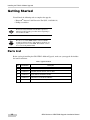
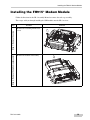
P O S I T I O N I N G
S Y S T E M S
GR-3 Modem to GSM/CDMA
Upgrade Installation Manual
Part Number 7010-0822
Rev. C
©Copyright Topcon Positioning Systems, Inc.
November, 2007
All contents in this manual are copyrighted by Topcon. All rights reserved. The information contained herein may not be
used, accessed, copied, stored, displayed, sold, modified, published, distributed, or otherwise reproduced without express
written consent from Topcon.
Terms and Conditions
Thank you for buying this Topcon product. This manual has been prepared to assist you with the servicing of the product
and its use/maintenance is subject to these Terms and Conditions and any more fully set forth in an Operator’s Manual.
Usage and Safety
This product is designed for use/service by professionals. Always use safety precautions when operating/servicing this or
any Topcon product.
Copyrights
All information contained in this Manual is the intellectual property of, and copyrighted material of TPS. All rights are
reserved. You may not use, access, copy, store, display, create derivative works of, sell, modify, publish, distribute, or
allow any third party access to, any graphics, content, information or data in this Manual without TPS’ express written
consent and may only use such information for the care and operation of your Product. The information and data in this
Manual are a valuable asset of TPS and are developed by the expenditure of considerable work, time and money, and are
the result of original selection, coordination and arrangement by TPS.
Trademarks
GR-3 and Topcon are trademarks or registered trademark of Topcon Positioning Systems, Inc. Windows and Outlook are
registered trademarks of Microsoft Corporation. InstallShield is a registered trademark of InstallShield Software
Corporation. The Bluetooth word mark and logos are owned by Bluetooth SIG, Inc. and any use of such marks by Topcon
Positioning Systems, Inc. is used under license.
Other product and company names mentioned herein may be trademarks of their respective owners.
Disclaimer of Warranty
EXCEPT FOR SUCH WARRANTIES AND LICENSES PROVIDED WITH THE PRODUCT, THIS MANUAL AND
THE PRODUCT ARE PROVIDED “AS-IS”. TOPCON AND ITS DISTRIBUTORS SHALL NOT BE LIABLE FOR
TECHNICAL OR EDITORIAL ERRORS OR OMISSIONS CONTAINED HEREIN; NOR FOR INCIDENTAL OR
CONSEQUENTIAL DAMAGES RESULTING FROM THE FURNISHING, PERFORMANCE OR USE OF THIS
MATERIAL OR THE PRODUCT.
Please see the Operator’s/User’s Manual for detailed information on warranties and the license agreement which may
apply to the Product.
License Agreement
Use of any computer programs or software supplied by Topcon or downloaded from the Topcon website in connection
with the Product implies acceptance of the Terms and Conditions here and in the Operator’s/User’s Manual.
Please see the Operator’s/User’s Manual for detailed information on warranties and the license agreement which may
apply to the Product.
Manual Conventions
This manual uses the following conventions.
NOTE
TIP
NOTICE
ECO#3181
Further information to note about the
configuration, maintenance, or setup of a
system.
Supplementary information that can help
you configure, maintain, or set up a system.
Supplementary information that can have
an affect on system operation, system
performance, measurements, or personal
safety.
CAUTION
WARNING
DANGER
Notification that an action has the potential
to adversely affect system operation,
system performance, data integrity, or
personal health.
Notification that an action will result in
system damage, loss of data, loss of
warranty, or personal injury.
Under no circumstances should this action
be performed.
TOC
Table of Contents
Chapter 1
Installing the FH915+ Modem Upgrade.........................1-1
Getting Started .....................................................................................
Parts List .........................................................................................
Installing the FH915+ Modem Module ...............................................
1-2
1-2
1-3
Chapter 2
Installing the Digital UHF Modem Upgrade ..................2-1
Getting Started .....................................................................................
Parts List .........................................................................................
Installing the Digital UHF Modem Module ........................................
P/N 7010-0822
2-2
2-2
2-3
i
Table of Contents
Notes:
ii
GR-3 Modem to GSM/CDMA Upgrade Installation Manual
Chapter 1
Installing the FH915+
Modem Upgrade
The GR-3 receiver is a multi-frequency, GPS+ receiver built to be the most advanced and compact
receiver for the surveying market. The following is a quick reference guide to the GR-3 Operator’s
Manual on installing the FH915+ Modem Upgrade.
Chapter Contents
“Getting Started” on page 2
“Installing the FH915+ Modem Module” on
page 3
P/N 7010-0822
1-1
Installing the FH915+ Modem Upgrade
Getting Started
You will need the following tools to complete the upgrade:
• Bluetooth® Antenna Cable Extraction Tool (P/N: 34-850402-01)
• Phillips screwdriver
NOTICE
Review all safety information in the GR-3 Operator’s
Manual and disassembly procedures before beginning to
disassemble the GR-3.
NOTE
Be sure to record the IMEI number on the new GSM
module for future reference. This number is needed to set
up telephone service for the GSM. This number can also
be accessed using Modem-TPS.
Parts List
Before you begin installing the GR-3 FH915+ Modem Upgrade, make sure your upgrade kit includes
the items listed below.
Table 1. Upgrade Contents
1-2
Qty
Part Number
Description
1
30-060001-01
MODULE,G24,GSM,850/900/1800/1900MHZ,EDGE
2
16-040803-01
SPACER, ROUND NYLON, OD 4 X 3MM
2
16-040802-01
NUT, HEX M2 STAINLESS STEEL
2
16-040801-01
SCR, M2.0 X 8 PAN HEAD PHILLIPS
1
14-004061-01
CABLE UMP/MMCX RA (0.04M)
GR-3 Modem to GSM/CDMA Upgrade Installation Manual
Installing the FH915+ Modem Module
Installing the FH915+ Modem Module
Follow the directions in the GR-3 Assembly Manual to remove the card cage assembly.
These steps walk you through installing the GSM module onto the GR-3 receiver.
Step 2: Remove the modem subassembly
Step 1: Remove the screw
Step
Procedure
Illustration
Remove the remaining middle-level
screw.
Remove the modem subassembly.
P/N 7010-0822
1-3
Installing the FH915+ Modem Upgrade
Step 5: Secure the module using
nuts and screws
Step 4: Place the modem module
onto the subassembly
Step 3: Connect the cable to
to the modem
Step
1-4
Procedure
Illustration
Connect the UMP/MMCX RA cable
to the FH915+ modem module.
Place the FH915+ module onto the
modem subassembly using the two
round nylon spacers.
Secure the FH915+module using the
two screws (M2,0x8 metric pan head
Phillips) and the two nuts (M2 metric
hex nut stainless steel) provided.
NOTE
Before securing the FH
915+ module, make
sure the connectors are
completely aligned
with the modem.
GR-3 Modem to GSM/CDMA Upgrade Installation Manual
Installing the FH915+ Modem Module
Step 8: Secure middle-level screws
Step 7: Insert modem subassembly
into the card cage
Step 6: Connect the cable to the
modem subassembly
Step
Procedure
Illustration
Connect the UMP/MMCX RA cable
to the modem subassembly.
Insert the modem subassembly into
the middle level of the card cage.
Secure the middle-level screw (M3x5
metric machine screw, Phillips,
stainless steel, pan head) into the card
cage.
Follow the directions in the GR-3 Assembly Manual to reinsert the card cage assembly.
P/N 7010-0822
1-5
Installing the FH915+ Modem Upgrade
Notes:
1-6
GR-3 Modem to GSM/CDMA Upgrade Installation Manual
Chapter 2
Installing the Digital UHF
Modem Upgrade
The GR-3 receiver is a multi-frequency, GPS+ receiver built to be the most advanced and compact
receiver for the surveying market. The following is a quick reference guide to the GR-3 Operator’s
Manual on installing the Digital UHF Modem Upgrade.
Chapter Contents
“Getting Started” on page 2-2
“Installing the Digital UHF Modem Module”
on page 2-3
P/N 7010-0822
2-1
Installing the Digital UHF Modem Upgrade
Getting Started
You will need the following tools to complete the upgrade:
• Bluetooth® Antenna Cable Extraction Tool (P/N: 34-850402-01)
• Phillips screwdriver
NOTICE
Review all safety information in the GR-3 Operator’s
Manual and disassembly procedures before beginning to
disassemble the GR-3.
NOTE
Be sure to record the IMEI number on the new GSM
module for future reference. This number is needed to set
up telephone service for the GSM. This number can also
be accessed using Modem-TPS.
Parts List
Before you begin installing the GR-3 Digital UHF Modem Upgrade, make sure your upgrade kit
includes one of the items listed below.
Table 1. Upgrade Contents
2-2
Qty
Part Number
Description
1
02-050915-02
PCBA ARWEST + EURO GSM
1
02-050915-03
PCBA Digital UHF + US GSM
1
02-050915-04
PCBA Digital UHF + Sprint CDMA
1
02-050915-05
PCBA Digital UHF + Verizon CDMA
GR-3 Modem to GSM/CDMA Upgrade Installation Manual
Installing the Digital UHF Modem Module
Installing the Digital UHF Modem Module
Follow the directions in the GR-3 Assembly Manual to remove the card cage assembly.
These steps walk you through removing the from the card cage.
Step 1: Remove the middle-level screw
Step
Procedure
Illustration
Remove the remaining middle-level
screw.
Step 2: Remove the modem subassembly
Remove the modem subassembly.
P/N 7010-0822
2-3
Step 4: Secure middle-level screw
Step 3: Insert the Digital UHF Modem
Installing the Digital UHF Modem Upgrade
Insert the Digital UHF Modem
module.
Secure the middle-level screw
Follow the directions in the GR-3 Assembly Manual to reinsert the card cage assembly.
2-4
GR-3 Modem to GSM/CDMA Upgrade Installation Manual
Installing the Digital UHF Modem Module
P/N 7010-0822
2-5
Installing the Digital UHF Modem Upgrade
Notes:
2-6
GR-3 Modem to GSM/CDMA Upgrade Installation Manual